

Videoswitch Vi-R5216L, Vi-R5516, Vi-R5532 Quick Operation Manual
R-Series NVR Quick
Operation Guide
Products covered by this manual
Vi-R5216L, Vi-R5516, Vi-R5532
Document Reference Date
Bdr604a.pdf
01/06/15
Videoswitch
Telephone
01252-851510
Unit 15 Redfields Industrial Park
Fax
01252-851296 Redfields
Lane, Church Crookham
Email
sales@videoswitch.co.uk
Hants GU52 0RD
Web
www.videoswitch.co.uk
Videoswitch R-Series NVR Quick Guide
2
Regulatory information
FCC information
FCC compliance: This equipment has been tested and found to comply with the limits for a digital device, pursuant
to part 15 of the FCC Rules. These limits are designed to provide reasonable protection against harmful
interference when the equipment is operated in a commercial environment. This equipment generates, uses, and
can radiate radio frequency energy and, if not installed and used in accordance with the instruction manual, may
cause harmful interference to radio communications. Operation of this equipment in a residential area is likely to
cause harmful interference in which case the user will be required to correct the interference at his own expense.
FCC conditions
This device complies with part 15 of the FCC Rules. Operation is subject to the following two conditions:
1. This device may not cause harmful interference.
2. This device must accept any interference received, including interference that may cause undesired operation.
EU Conformity Statement
This product and - if applicable - the supplied accessories too are marked with "CE" and comply therefore with the
applicable harmonized European standards listed under the Low Voltage Directive 2006/95/EC, the EMC
Directive 2004/108/EC, the RoHS Directive 2011/65/EU.
2012/19/EU (WEEE directive): Products marked with this symbol cannot be disposed of as unsorted municipal
waste in the European Union. For proper recycling, return this product to your local supplier upon the purchase of
equivalent new equipment, or dispose of it at designated collection points. For more information see:
www.recyclethis.info.
2006/66/EC (battery directive): This product contains a battery that cannot be disposed of as unsorted municipal
waste in the European Union. See the product documentation for specific battery information. The battery is
marked with this symbol, which may include lettering to indicate cadmium (Cd), lead (Pb), or mercury (Hg). For
proper recycling, return the battery to your supplier or to a designated collection point. For more information see:
www.recyclethis.info.
Trademarks and Registered Trademarks
Windows and Windows mark are trademarks or registered trademarks of Microsoft Corporation in the United
States and/or other countries.
HDMI, HDMI mark and High-Definition Multimedia Interface are trademarks or registered trademarks of
HDMI Licensing LLC.
The products contained in this manual are authorized by HDMI Licensing LLC with the use right of the
HDMI
technology.
VGA is the trademark of IBM.
UPnPTM is a certification mark of the UPnPTM Implementers Corporation.
Other names of companies and product contained in this manual may be trademarks or registered trademarks
of their respective owners.

Videoswitch R-Series NVR Quick Guide
3
Thank you for purchasing our product. If there is any question or request, please do not hesitate to contact
dealer. This manual is applicable to the models listed:
NVR Pre-Installation
The NVR is highly advanced surveillance equipment that should be installed with care. Please take into
consideration the following precautionary steps before installation of the NVR.
1. Keep all liquids away from the NVR.
2. Install the NVR in a well-ventilated and dust-free area.
3. Ensure environmental conditions meet factory specifications.
4. Install a manufacturer recommended HDD.
NVR Installation
During the installation of the NVR:
1. Use brackets for rack mounting.
2. Ensure there is ample room for audio and video cables.
3. When routing cables, ensure that the bend radius of the cables are no less than five times than its
diameter.
4. Connect the alarm cable.
5. Allow at least 2cm (≈0.75-inch) of space between racks mounted devices.
6. Ensure the NVR is grounded.
Vi-R5216L
Vi-R5516
7. Environmental temperature should be within the range of -10 ºC ~ 5 5 ºC, 14ºF ~ 131ºF.
8. Environmental humidity should be within the range of 10% ~ 90%.
Videoswitch R-Series NVR Quick Guide
6
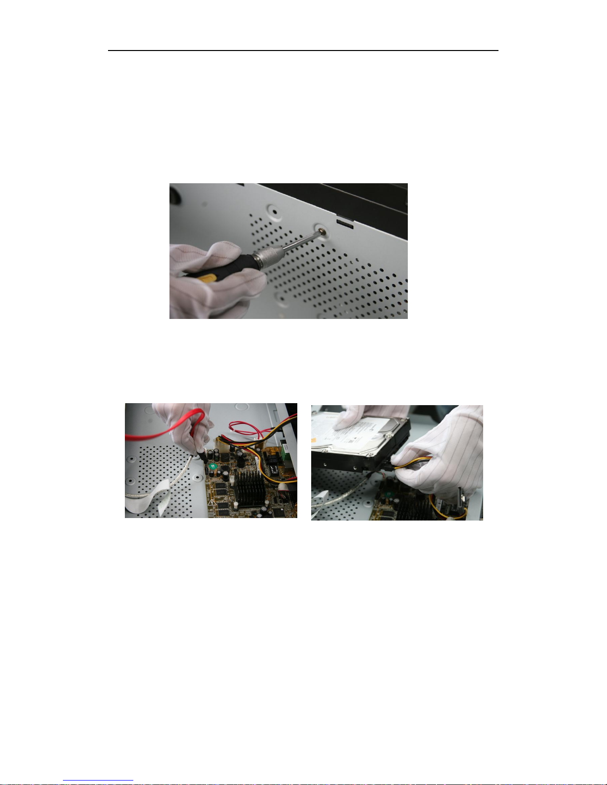
1. Remove the cover from the NVR by unfastening the screws on the rear and side panel.
2. Connect one end of the data cable to the motherboard of NVR and the other end to the HDD.
Hard Disk Installation
Videoswitch R-Series NVR Quick Guide
7
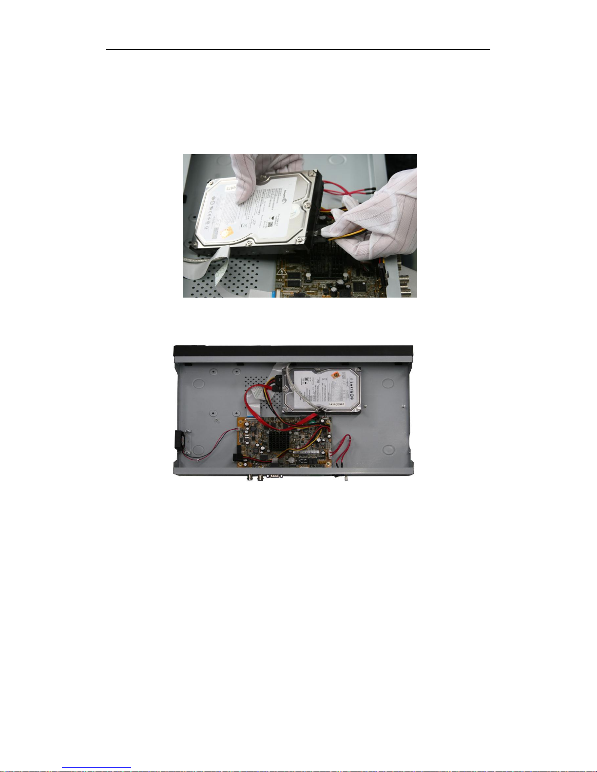
4. Place the HDD on the bottom of the device and then fasten the screws on the bottom to fix the HDD.
3. Connect the power cable to the HDD.
Videoswitch R-Series NVR Quick Guide
11
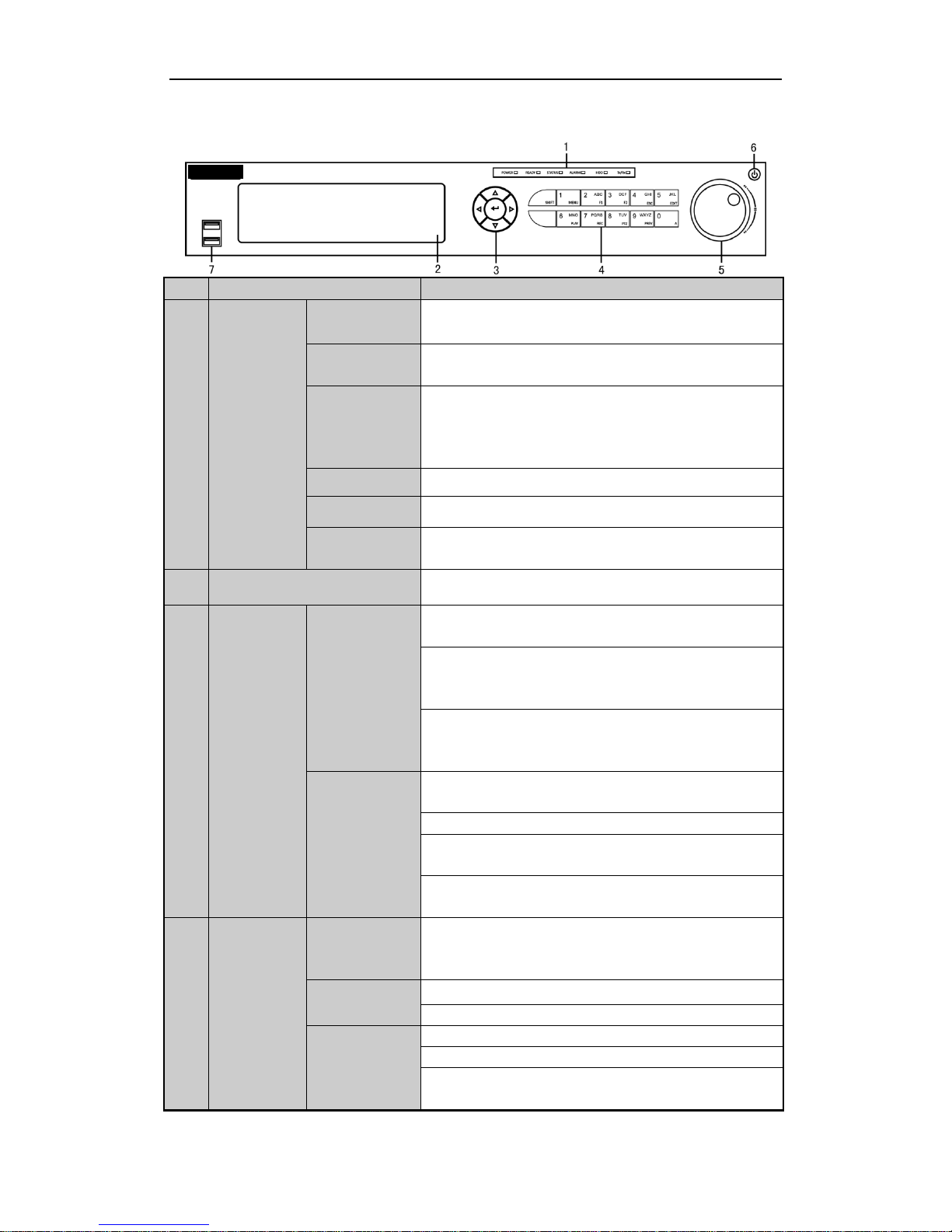
Vi-R5516
No.
Name
Function Description
1
Status
Indicators
POWER
Turns green when NVR is powered up.
READY
The LED is green when the device is running normally.
STATUS
The light is green when the IR remote control is enabled;
The light is red when the function of the composite keys (SHIFT)
are used;
The light is out when none of the above condition is met.
ALARM
The light is red when there is an alarm occurring.
HDD
Blinks red when HDD is reading/writing.
Tx/Rx
Blinks green when network connection is functioning normally.
2
DVD-R/W
Slot for DVD-R/W.
3
Control
Buttons
DIRECTION
In menu mode, the direction buttons are used to navigate between
different fields and items and select setting parameters.
In playback mode, the Up and Down buttons are used to speed up
and slow down record playing, and the Left and Right buttons are
used to move the recording 30s forwards or backwards.
In the image setting interface, the up and down button can adjust
the level bar of the image parameters.
In live view mode, these buttons can be used to switch channels.
ENTER
The Enter button is used to confirm selection in menu mode; or
used to check checkbox fields and ON/OFF switch.
In playback mode, it can be used to play or pause the video.
In single-frame play mode, pressing the Enter button will play the
video by a single frame.
In auto sequence view mode, the buttons can be used to pause or
resume auto sequence.
4
Composite
Keys
SHIFT
Switch between the numeric or letter input and functions of the
composite keys. (Input letter or numbers when the light is out;
Realize functions when the light is red.)
1/MENU
Enter numeral “1”;
Access the main menu interface.
2/ABC/F1
Enter numeral “2”;
Enter letters “ABC”;
The F1 button when used in a list field will select all items in the
list.
Front Panel
Videoswitch R-Series NVR Quick Guide
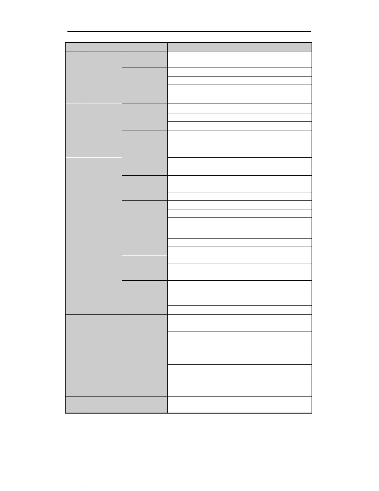
12
No.
Name
Function Description
In PTZ Control mode, it will turn on/off PTZ light and when the
image is zoomed in, the key is used to zoom out.
3/DEF/F2
Enter numeral “3”;
Enter letters “DEF”;
The F2 button is used to change the tab pages.
In PTZ control mode, it zooms in the image.
4/GHI/ESC
Enter numeral “4”;
Enter letters “GHI”;
Exit and back to the previous menu.
5/JKL/EDIT
Enter numeral “5”;
Enter letters “JKL”;
Delete characters before cursor;
Check the checkbox and select the ON/OFF switch;
Start/stop record clipping in playback.
6/MNO/PLAY
Enter numeral “6”;
Enter letters “MNO”;
Playback, for direct access to playback interface.
7/PQRS/REC
Enter numeral “7”;
Enter letters “PQRS”;
Open the manual record interface.
8/TUV/PTZ
Enter numeral “8”;
Enter letters “TUV”;
Access PTZ control interface.
9/WXYZ/PRE
V
Enter numeral “9”;
Enter letters “WXYZ”;
Multi-channel display in live view.
0/A
Enter numeral “0”;
Shift the input methods in the editing text field. (Upper and
lowercase, alphabet, symbols or numeric input).
Double press the button to switch the main and auxiliary output.
5
JOG SHUTTLE Control
Move the active selection in a menu. It will move the selection up
and down.
In Live View mode, it can be used to cycle through different
channels.
In the Playback mode, it can be used to jump 30s
forward/backward in video files.
In PTZ control mode, it can control the movement of the PTZ
camera.
6
POWER ON/OFF
Power on/off switch.
7
USB Interfaces
Universal Serial Bus (USB) ports for additional devices such as
USB mouse and USB Hard Disk Drive (HDD).
Videoswitch R-Series NVR Quick Guide
13
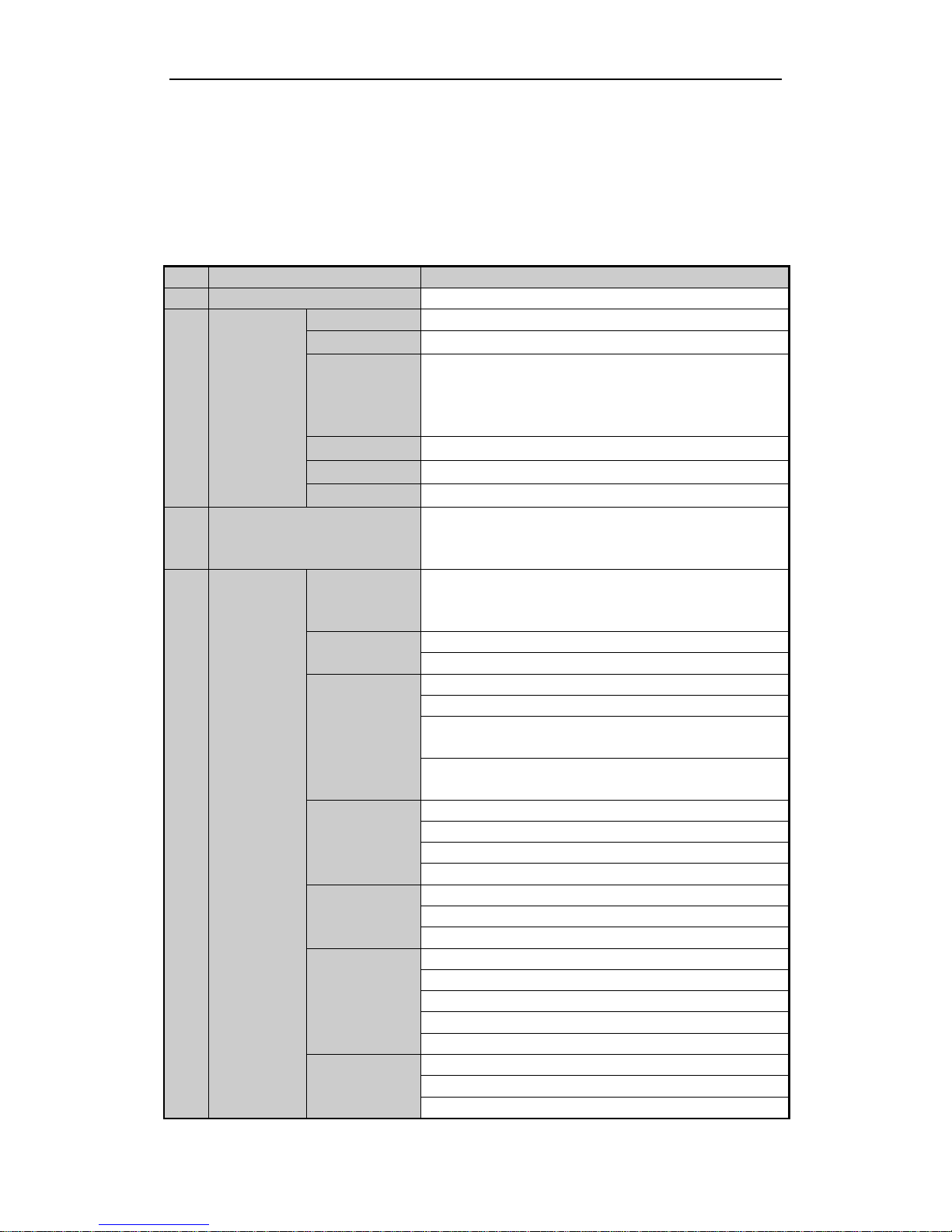
Vi-R5216:
No.
Name
Function Description
1
USB Interface
Connects USB mouse or USB flash memory devices.
2
Status
Indicators
POWER
Turns green when NVR is powered up.
READY
The LED is green when the device is running normally.
STATUS
The light is green when the IR remote control is enabled;
The light is red when the function of the composite keys (SHIFT)
are used;
The light is out when none of the above condition is met.
ALARM
The light is red when there is an alarm occurring.
HDD
Blinks red when HDD is reading/writing.
Tx/Rx
Blinks green when network connection is functioning normally.
3
SHIFT
Switch between the numeric or letter input and functions of the
composite keys. (Input letter or numbers when the light is out;
Realize functions when the light is red.)
4
Composite
Keys
SHIFT
Switch between the numeric or letter input and functions of the
composite keys. (Input letter or numbers when the light is out;
Realize functions when the light is red.)
1/MENU
Enter numeral “1”;
Access the main menu interface.
2/ABC/F1
Enter numeral “2”;
Enter letters “ABC”;
The F1 button when used in a list field will select all items in the
list.
In PTZ Control mode, it will turn on/off PTZ light and when the
image is zoomed in, the key is used to zoom out.
3/DEF/F2
Enter numeral “3”;
Enter letters “DEF”;
The F2 button is used to change the tab pages.
In PTZ control mode, it zooms in the image.
4/GHI/ESC
Enter numeral “4”;
Enter letters “GHI”;
Exit and back to the previous menu.
5/JKL/EDIT
Enter numeral “5”;
Enter letters “JKL”;
Delete characters before cursor;
Check the checkbox and select the ON/OFF switch;
Start/stop record clipping in playback.
6/MNO/PLAY
Enter numeral “6”;
Enter letters “MNO”;
Playback, for direct access to playback interface.
Videoswitch R-Series NVR Quick Guide
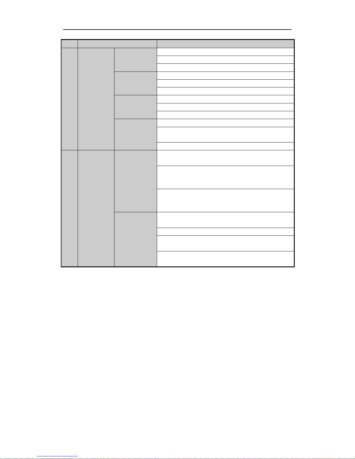
14
No.
Name
Function Description
7/PQRS/REC
Enter numeral “7”;
Enter letters “PQRS”;
Open the manual record interface.
8/TUV/PTZ
Enter numeral “8”;
Enter letters “TUV”;
Access PTZ control interface.
9/WXYZ/PRE
V
Enter numeral “9”;
Enter letters “WXYZ”;
Multi-channel display in live view.
0/A
Enter numeral “0”;
Shift the input methods in the editing text field. (Upper and
lowercase, alphabet, symbols or numeric input).
Double press the button to switch the main and auxiliary output.
5
Control
Buttons
DIRECTION
In menu mode, the direction buttons are used to navigate between
different fields and items and select setting parameters.
In playback mode, the Up and Down buttons are used to speed up
and slow down record playing, and the Left and Right buttons are
used to move the recording 30s forwards or backwards.
In the image setting interface, the up and down button can adjust
the level bar of the image parameters.
In live view mode, these buttons can be used to switch channels.
ENTER
The Enter button is used to confirm selection in menu mode; or
used to check checkbox fields and ON/OFF switch.
In playback mode, it can be used to play or pause the video.
In single-frame play mode, pressing the Enter button will play the
video by a single frame.
In auto sequence view mode, the buttons can be used to pause or
resume auto sequence.
 Loading...