

Page 1
M-series Digital Recorder
User Manual
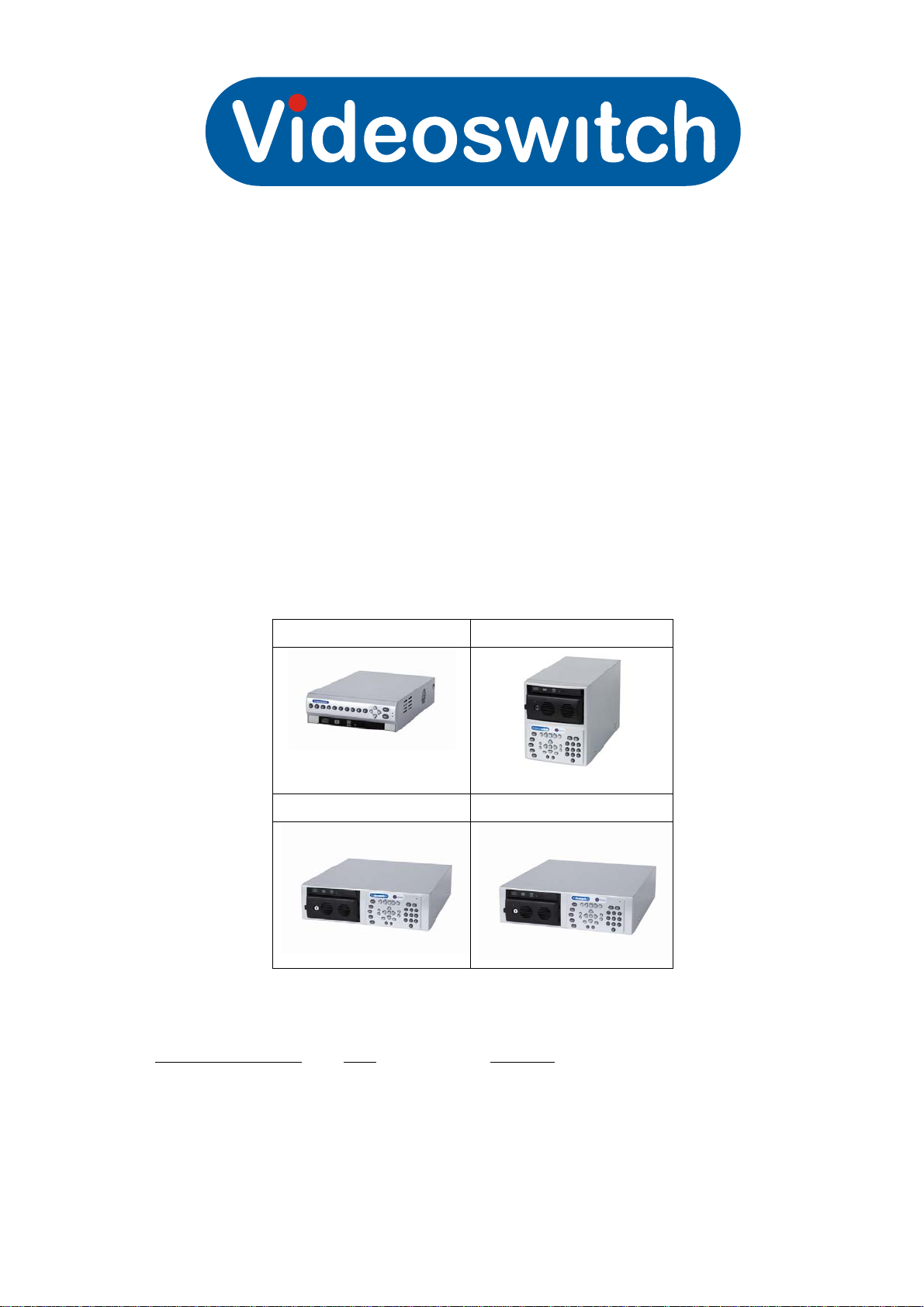
Product ranges covered by this manual
Vi-M1 Vi-M2
Vi-M3 Vi-M4
Document Reference Date Firmware
Vip601a.doc 12/05/2009 From Vip004#1818
Videoswitch
Ocean House, Redfields Industrial Park Fax 01252-851296
Redfields Lane, Church Crookham Email [email protected]
Hants GU52 0RD Web www.videoswitch.co.uk
Telephone 01252-851510
Page 2

Vip601a.doc
Page 3

Digital Recorder
Contents:
1 Start Here ..................................................................1
1.1 Connecting Up the Vi-M1.......................................................................................................2
1.2 Connecting Up the Vi-M2.......................................................................................................3
1.3 Connecting up the Vi-M3 & Vi-M4..........................................................................................4
1.4 Setting Date/Time ..................................................................................................................4
1.5 Recording...............................................................................................................................5
1.6 Routine Checks......................................................................................................................5
1.7 Care of the Hard Drive(s).......................................................................................................5
1.8 Critical Alerts..........................................................................................................................5
2 Control.......................................................................6
2.1 Mini Keypad ...........................................................................................................................6
2.2 Standard Keypad ...................................................................................................................8
2.3 Live Viewing.........................................................................................................................11
1.1.1 Viewing Full Screen Images ............................................................................................11
1.1.1.1 Quad Display..................................................................................................11
1.1.1.2 Multi-Screen...................................................................................................11
1.1.2 Spot monitor(s) ................................................................................................................11
1.1.3 Tagging Images ...............................................................................................................12
2.4 Playback...............................................................................................................................13
3 Navigation...............................................................15
3.1 Menus ..................................................................................................................................15
3.2 Mini-Keypad.........................................................................................................................15
3.3 Standard Keypad .................................................................................................................15
3.4 Summary of keys used in menus.........................................................................................16
4 Find..........................................................................18
4.1 Date/Time.............................................................................................................................18
4.2 Events..................................................................................................................................18
1.1.4 Alarm................................................................................................................................18
1.1.5 System.............................................................................................................................18
1.1.6 Critical..............................................................................................................................18
5 Burn.........................................................................19
5.1 Edit Incident .........................................................................................................................19
5.2 Incident List..........................................................................................................................20
6 Menus......................................................................21
6.1 Date/Time.............................................................................................................................21
1.1.7 System date/time.............................................................................................................21
1.1.8 Date format ......................................................................................................................21
6.2 Record..................................................................................................................................22
1.1.9 Record settings................................................................................................................22
1.1.1.3 Mode ..............................................................................................................22
1.1.1.4 Format............................................................................................................22
1.1.1.5 Quality............................................................................................................23
1.1.1.6 Auto Retention................................................................................................23
1.1.1.7 Custom Rate per camera ...............................................................................23
1.1.1.8 Alarm rate per camera....................................................................................23
1.1.10 Record audio....................................................................................................................23
6.3 Display .................................................................................................................................23
1.1.11 Titles ................................................................................................................................23
1.1.1.9 Server.............................................................................................................23
i
Page 4

Digital Recorder
1.1.1.10 Camera Titles.................................................................................................24
1.1.1.11 Show Camera Titles.......................................................................................24
1.1.1.1.1 Full 24
1.1.1.1.2 Quad 24
1.1.1.1.3 x9 24
1.1.1.1.4 x16 24
1.1.1.12 Auto sequence (main monitor) .......................................................................24
1.1.1.1.5 Sequence Mode 24
1.1.1.1.6 Camera List 24
1.1.1.1.7 Dwell times 25
1.1.1.1.8 Dwell times (all) 25
1.1.1.13 Auto sequence (spot monitor) ........................................................................25
1.1.1.1.9 Spot1 25
1.1.1.1.10 Sequence Mode 25
1.1.1.1.11 Camera List 25
1.1.1.1.12 Dwell times 25
1.1.1.1.13 Dwell times (all) 25
1.1.1.14 Spot monitor options ......................................................................................25
1.1.1.1.14 Spot1 25
1.1.1.15 Power-up options ...........................................................................................26
1.1.1.1.15 Main monitor format 26
6.4 Alarms..................................................................................................................................26
1.1.12 Alarm inputs.....................................................................................................................26
1.1.1.16 Alarm polarities...............................................................................................26
1.1.1.17 Camera mapping............................................................................................26
1.1.1.18 Alarm timers ...................................................................................................26
1.1.1.19 Weekday alarm times.....................................................................................26
1.1.1.20 Weekend alarm times.....................................................................................26
1.1.1.21 Enable alarms all day.....................................................................................27
1.1.13 Activity..............................................................................................................................27
1.1.1.22 Activity timers .................................................................................................27
1.1.1.23 Weekday activity times...................................................................................27
1.1.1.24 Weekend activity times...................................................................................27
1.1.1.25 Enable activity all day.....................................................................................27
1.1.14 Critical alerts....................................................................................................................27
1.1.1.1.16 Videloss 27
1.1.1.1.17 Record stopped 27
1.1.1.1.18 Hard drives 27
1.1.15 Clear critical alerts ...........................................................................................................28
1.1.16 Erase event list ................................................................................................................28
1.1.17 Pull-up and restore...........................................................................................................28
1.1.1.1.19 Pull-up monitor 28
1.1.1.1.20 Pull-up hold time 28
1.1.1.1.21 Pull-up sequence time 28
1.1.1.1.22 Relay hold time 28
1.1.1.1.23 Restore camera 28
1.1.18 Relay activation................................................................................................................28
1.1.1.26 Use relay1 for alarm.......................................................................................28
1.1.1.27 Use relay2 for critical alert..............................................................................29
6.5 Network................................................................................................................................29
1.1.19 IP address........................................................................................................................29
1.1.20 Ports.................................................................................................................................29
1.1.1.28 Command.......................................................................................................29
1.1.1.29 Video ..............................................................................................................29
ii
Page 5

Digital Recorder
1.1.21 Sub-net mask...................................................................................................................29
1.1.22 Gateway...........................................................................................................................29
1.1.23 MTU .................................................................................................................................30
6.6 Configuration........................................................................................................................30
1.1.24 Language.........................................................................................................................30
1.1.25 Unit number .....................................................................................................................30
1.1.26 Display.............................................................................................................................30
1.1.1.30 VGA resolution ...............................................................................................30
1.1.1.31 VGA gamma...................................................................................................30
1.1.1.32 VGA motion....................................................................................................30
1.1.1.33 Menu translucency .........................................................................................30
1.1.1.34 Boundary colour .............................................................................................30
1.1.27 Camera inputs..................................................................................................................30
1.1.1.35 Termination ....................................................................................................30
1.1.28 Passwords .......................................................................................................................31
1.1.1.36 Logged off user ..............................................................................................31
1.1.1.1.24 Access rights 31
1.1.1.37 Named users..................................................................................................31
1.1.1.1.25 User1..User4 31
1.1.29 Coverts.............................................................................................................................31
1.1.1.38 Covert cameras (Main)...................................................................................31
1.1.1.39 Covert cameras (Spot1).................................................................................31
1.1.30 Restore factory defaults...................................................................................................31
1.1.31 Restart the system...........................................................................................................31
7 Help..........................................................................33
7.1 Status/Config........................................................................................................................33
1.1.32 Config...............................................................................................................................33
1.1.33 Status...............................................................................................................................33
1.1.34 Drives...............................................................................................................................34
1.1.35 Drive1...............................................................................................................................34
1.1.36 Record .............................................................................................................................35
8 Function ..................................................................36
9 Password ................................................................37
10 Connections............................................................38
10.1 Ethernet connection to Broadband ......................................................................................38
10.2 Ethernet connection to a PC................................................................................................38
10.3 Ethernet connection to a LAN..............................................................................................39
10.4 Audio....................................................................................................................................39
10.5 Multi Unit Cascading............................................................................................................40
11 Technical Data........................................................41
11.1 Accessories Included...........................................................................................................41
11.2 Changing the Hard Drive .....................................................................................................41
1.1.37 Changing a hard drive - Vi-M1.........................................................................................41
1.1.38 Changing a hard drive - Vi-M2/Vi-M3/Vi-M4....................................................................42
1.1.39 Alarms, Domes, Relays ...................................................................................................43
1.1.40 Main Keyboard Port .........................................................................................................44
1.1.41 Spot Keyboard/Cascade Port ..........................................................................................44
11.3 Specifications.......................................................................................................................45
1.1.42 Storage ............................................................................................................................45
1.1.43 Digital recording/Replay...................................................................................................45
1.1.44 Display.............................................................................................................................45
iii
Page 6

Digital Recorder
1.1.45 Control and Interface .......................................................................................................46
1.1.1.40 Dome Control .................................................................................................46
1.1.1.41 Remote Viewing .............................................................................................47
1.1.46 Power, Physical & Environmental....................................................................................48
1.1.47 Upgrades .........................................................................................................................48
1.1.48 CE Marking......................................................................................................................49
1.1.49 Ventilation........................................................................................................................49
1.1.50 Safety...............................................................................................................................49
12 Warranty Fax-Back.................................................51
iv
Page 7

Digital Recorder
1 Start Here
Please fill in the warranty fax-back form on page 51 and return it to Videoswitch
• The Vi-M1, Vi-M2, Vi-M3 and Vi-M4 digital recorders from Videoswitch are part of
the M-series range
• These products are designed to be easy to use whilst offering high quality digital
video recording and playback, primarily for CCTV security applications.
• The video images from all connected cameras are continuously recorded onto the
built-in hard drives. When the drives are full, the M-series keeps on recording,
overwriting the oldest images.
• Images are retained for a specified user programmable number of days, typically
31. All images recorded within the period will be available for replay. Older image
are no longer available.
• Several methods are provided for finding the recorded images you want quickly,
including date/time searches and activity or alarm event searches
• The built-in DVD writer allows a selected part or parts of the recorded information to
be written onto a DVD or CD, typically to back-up an incident for use as evidence by
the Police.
• A USB interface allows incidents to be backed up to USB memory sticks as an
alternative to DVD or CD
• The recording process continues all the time, even when playing back or backing up
incidents
• Dual channel audio recording is standard on the M-series
• Ethernet is also a standard feature allowing remote viewing via a local area network
(LAN) or via Broadband Ethernet
• Multiple Vi-M3 and Vi-M4 DVRs may be cascaded to cater for larger numbers of
cameras. Build in matrix switching combines monitor outputs so that the group of
DVRs can drive one (BNC) main monitor and 3 independent spot monitors.
• Software updates may be installed via CD, USB memory stick or via ethernet
Note:
This manual covers a range of products and therefore describes features that do not exist in
all models.
1
Page 8
Digital Recorder
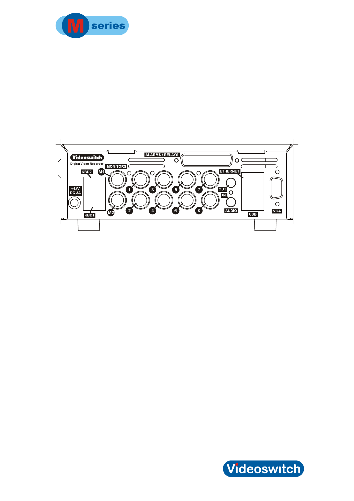
1.1 Connecting Up the Vi-M1
For a standard digital recording system you will need
• The Vi-M1 recorder
• Some cameras with lenses
• A video monitor (with BNC composite video input) or a VGA monitor
• BNC cables
• Connect the monitor output (M1) of the Vi-M1 to a Video Monitor using a BNC
cable. Alternatively or additionally, connect a VGA monitor to the VGA output
• Make sure that the monitor termination is switched on (i.e. to 75 Ohms)
• On 8-camera models, a spot monitor may also be connected, to output M2
• Connect a camera to Camera Input 1 on the Vi-M1 using a BNC cable
• Connect further cameras to Inputs 2,3,4 etc
• Make sure that the mains supply is rated at the correct mains voltage. In UK and
Europe this is normally 230Vac
• Connect the mains power using the mains cable provided
2
Page 9
Digital Recorder
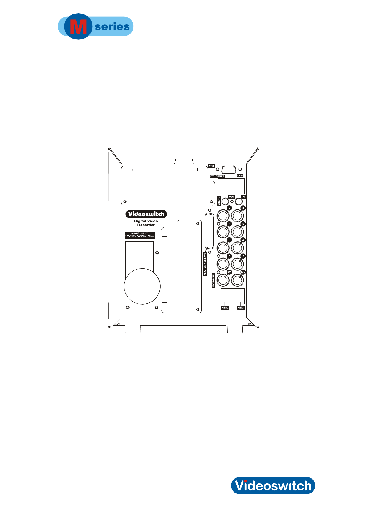
1.2 Connecting Up the Vi-M2
For a standard digital recording system you will need
• The Vi-M2 recorder
• Some cameras with lenses
• A video monitor (with BNC composite video input) or a VGA monitor
• BNC cables
• Connect the monitor output (M1) of the Vi-M2 to a Video Monitor using a BNC
cable. Alternatively or additionally, connect a VGA monitor to the VGA output
• Make sure that the monitor termination is switched on (i.e. to 75 Ohms)
• On 8-camera models, a spot monitor may also be connected, to output M2.
• Connect a camera to Camera Input 1 on the Vi-M2 using a BNC cable
• Connect further cameras to Inputs 2,3,4 etc
• Make sure that the voltage select switch (if present) is set to suit the mains supply.
The setting required in UK and Europe is normally 230Vac
• Connect the mains power using the mains cable provided
3
Page 10
Digital Recorder
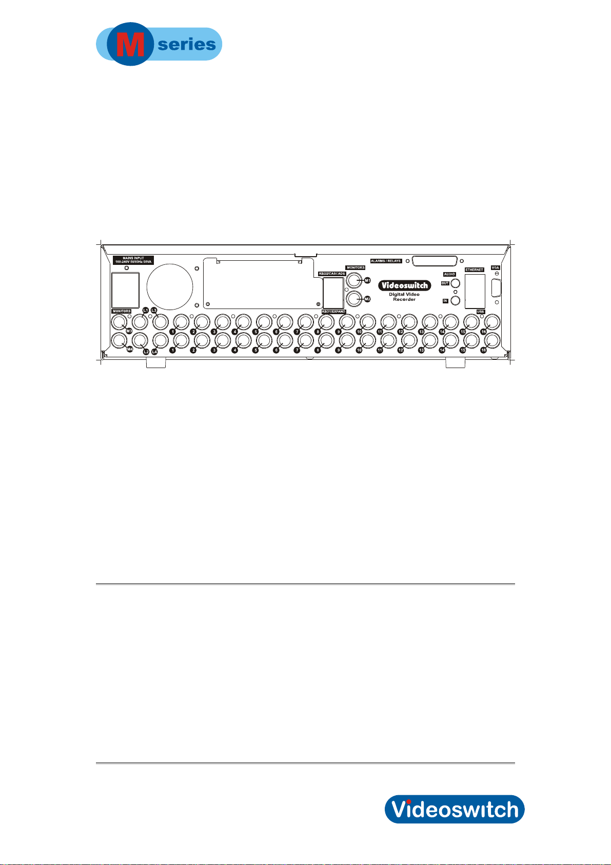
1.3 Connecting up the Vi-M3 & Vi-M4
For a standard digital recording system you will need
• The Vi-M3 recorder
• Some cameras with lenses
• A video monitor (with BNC composite video input) or a VGA monitor
• BNC cables
• Connect the monitor output (MAIN) of the Vi-M3 to a Video Monitor using a BNC
cable. Alternatively or additionally, connect a VGA monitor to the VGA output
• Make sure that the monitor termination is switched on (i.e. to 75 Ohms)
• Up to 3 other spot monitors may be connected to outputs M2, M3 and M4 (or 2 spot
monitor on 12-camera models)
• Connect a camera to Camera Input 1 on the Vi-M3using a BNC cable
• Connect further cameras to Inputs 2,3,4 etc
• Make sure that the voltage select switch (if present) is set to suit the mains supply.
The setting required in UK and Europe is normally 230Vac.
• Connect the mains power using the mains cable provided
1.4 Setting Date/Time
For proper operation of the M-series DVR Digital Recorder it is essential that the date
and time are set correctly.
If the system clock has an invalid date or time when the M-series DVR is powered up or at
any time during operation, the displayed date and time in live mode will replaced by dashes.
If the clock needs setting, refer to section
Note that the time is automatically adjusted forwards or backwards by an hour at the
appropriate dates to take account of British Summertime (daylight saving) so no user action
is required.
1.1.7 page 21.
4
Page 11

Digital Recorder
1.5 Recording
Once the Date/time is set the M-series DVR Digital Recorder should now be fully
operational and recording images from all connected cameras. The default image retention
period is 31 days unless set otherwise in the menu.
1.6 Routine Checks
If the M-series DVR is not recording, the message RECORDING STOPPED will be
displayed on the video monitor. This should only happen if there is no video, if no hard drive
is fitted or if it is faulty, or if record timers have been set to disable recording. If recording
stops when is should not, a critical alert will occur, displayed as a red message on the
screen. This indicates that there may be a fault with the DVR or with one of its hard drives.
Although the system is intended for continuous un-attended operation,
that the user regularly check that images from all cameras replay correctly. Any
potential problems with the cameras or recording system will then be detected as soon a
possible, rather than continuing un-noticed until a critical incident needs to be recalled from
the system.
Similarly,
plays back correctly, before the images on the hard drive in the M-series DVR become
over-written. The backup may be checked by either by playing it on the M-series DVR or on
a PC.
when a DVD, CD or USB backup has been created you should check that it
it is recommended
1.7 Care of the Hard Drive(s)
A hard drive is a delicate mechanical item that should be handled with care. Before moving
a M-series DVR that has been powered up, or removing a hard drive, remove power and
wait for 30 seconds for the drive to stop spinning. This is a precaution to avoid possible
damage to the hard drive.
1.8 Critical Alerts
The M-series DVR constantly monitors the hard drive, camera inputs and system so that
detected fault conditions will be reported to the user as soon as possible by means of a red
“critical alert” message on the top left of the screen. Critical alerts are also added to the
event list.
• To cancel a critical alert, press the FIND key several times until the Critical event
screen is displayed. In the case of a Vi-M1, access events via the menu by pressing
the SEL key and navigating the menu with up, down and SEL.
• When viewing the events, use the up, down, left, right keys to scroll through the
lines and pages. If there are lots of events, you can press DEFAULT to see latest
alerts, and press DEFAULT again to see earliest. Press SEL to cancel the currently
elected critical alert. If there are a lot of critical alerts to cancel, they can all be
cleared in the Alarms menu
• If critical alert condition persists, the red message will re-appear indicating that a
fault exists that needs attention.
5
Page 12
Digital Recorder
2 Control
2.1 Mini Keypad
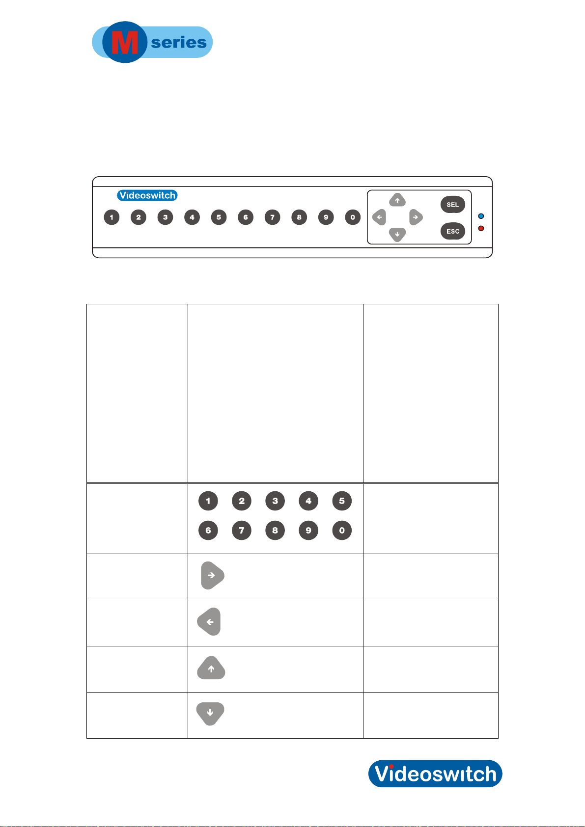
The Vi-M1 has a mini-keypad with the key layout as above. All functions can be controlled
by the 16 keys provided. Two functions are achieved by holding down the SEL or ESC key
for 1 second:
Names of keys used
number
right
left
up
Keypad legend
Used for
Select cameras and enter
numbers when in the menu
Play forwards in playback
mode, navigate in menu
Go back in play mode, navigate
in menu
Go back in play mode, navigate
in menu
down
Pause in play mode, navigate
in menu
6
Page 13
Digital Recorder
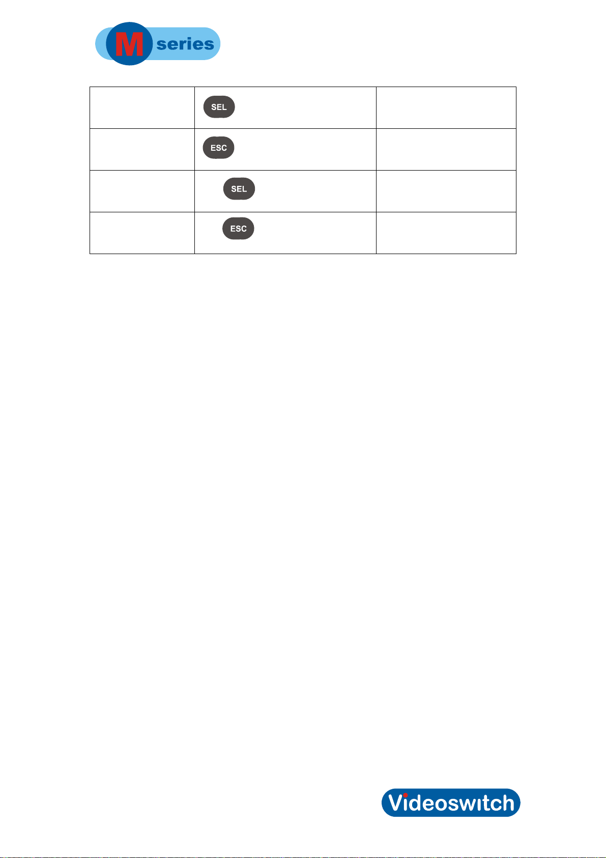
SEL
ESC
DEFAULT
EXIT
Hold for 1 second
Hold for 1 second
Enter root menu or select or
confirm within the menu
Escape from current menu
level to prior level
Set a menu setting to default
value, set a TAG in the event
log.
Exit from menu, go to live mode
7
Page 14
Digital Recorder
2.2 Standard Keypad
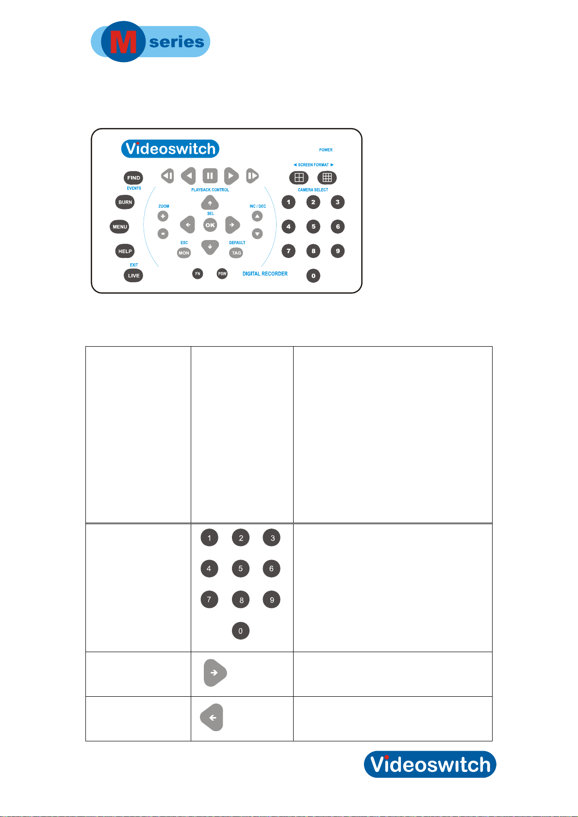
The Vi-M2, Vi-M3 and Vi-M4 have a standard keypad with the key layout as above. All
functions can be controlled by the 35 keys provided:
Names of keys used
Number
Keypad legend Used for
Used to select cameras and enter numbers
when in the
menu
Right
Left
Pan dome right in live mode, navigate in
menu
Pan dome left in live mode, navigate in
menu
8
Page 15
Digital Recorder
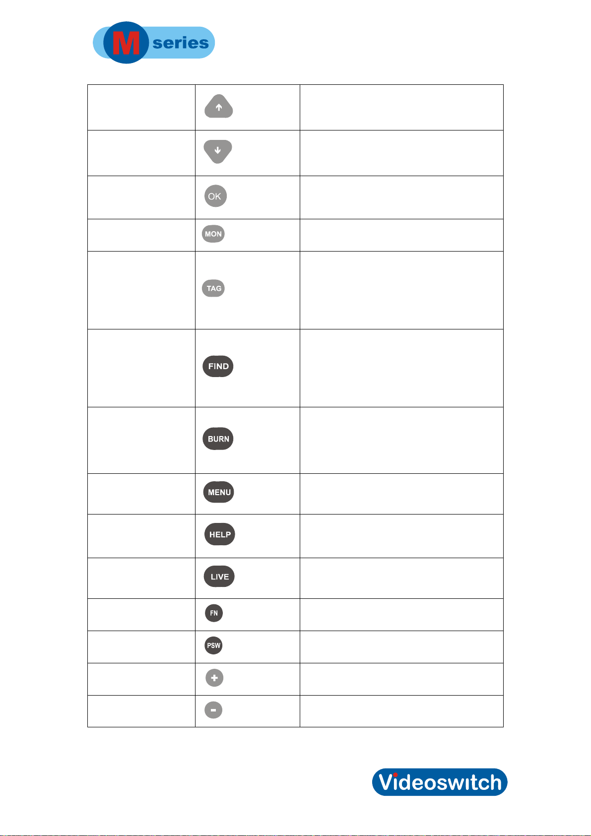
Up
Down
SEL
ESC
DEFAULT
FIND
Tilt dome up in live mode, navigate in menu
Tilt dome down in live mode, navigate in
Enter root menu or select or confirm within
Escape from current menu level to prior
Set a TAG in the event log in live or play
Press once for date/time search, press
menu
the menu
level
mode, set
a default
value in
menu
mode
again for
event log,
system log
and critical
alert log
BURN
MENU
HELP
EXIT
FN
PSW
Plus
Press once for incident and burn (backup)
screen.
Press
Enter main menu
Show status screen. Press for subsequent
Exit from menu, go to live mode
Enter function screen
Enter password screen
Select title options in menu, zoom dome
again for
incident l
next status
screens
ist.
Minus
Select title options in menu, zoom dome
9
Page 16
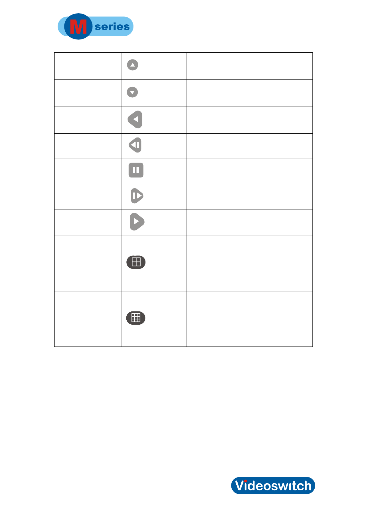
Inc
Dec
Digital Recorder
Select next camera, insert space when
Select prior camera, delete character when
editing title
in menu
editing title
in menu
Play_Back
Step_Back
Pause
Step_Forward
Play
Quad
Multi-screen
Step back in playback mode
Step back in playback mode
Pause playback
Step forwards in playback mode
Play forward in playback mode
Display camera 1-4 on the main monitor.
Press
again to
display the
Display camera 1-9 on the main monitor.
next four
cameras (if
present)
Press
again to
display
cameras 116 (if
present)
10
Page 17

Digital Recorder
2.3 Live Viewing
On a standard keypad, press this LIVE/EXIT key to enter live mode:
On a mini-keypad, press the ESC key and hold for 1 second to enter live mode:
1.1.1 Viewing Full Screen Images
To select cameras 1 to 9 for viewing press the required number key and wait a moment for
the camera to select (or press two number keys 01, 02, 03 etc in fairly quick succession)
To select any cameras 10 to 16, press two number keys 10, 11, 12, 13, 14, 15 or 16 in fairly
quick succession.
You can also select cameras using the Inc and Dec keys
1.1.1.1 Quad Display
Select quad display on the main monitor by pressing the Quad key. Cameras 1, 2, 3 and 4
will be displayed together.
Press again to see cameras 5, 6, 7 and 8. Successive presses will select the next set of
four camera images.
Note that on a mini-keypad there is no Quad key. In this case, press the ESC key to cycle
through the various screen modes.
Press a number key to revert to full screen display of one camera.
1.1.1.2 Multi-Screen
Select quad display on the main monitor by pressing the Multiscreen key. Cameras 1-9 will
be displayed together.
Press again to see cameras 1-16. Successive presses will step between the modes.
Note that on a mini-keypad there is no Multiscreen key. In this case, press the ESC key to
cycle through the various screen modes.
Press a number key to revert to full screen display of one camera.
1.1.2 Spot monitor(s)
• On a standard keypad, press the MON key to select the required monitor.
• On a mini-keypad, press and hold the ESC key to select the required monitor.
• The selected monitor is indicated on bottom right of screen prior to the camera number.
If no monitor is indicated, then it is the main monitor that is selected.
11
Page 18

Digital Recorder
• Having selected the required monitor, select the camera to be displayed by pressing the
number keys
1.1.3 Tagging Images
• If you something occurs that you may wish to go back to, press the TAG key to create
an event in the alarms event log
• In the case of a mini-keypad (Vi-M1) press and hold the SEL key to create a tag.
12
Page 19
Digital Recorder
2.4 Playback
• If there is a DVD or CD that has previously stored images on it in the DVD drive, the Mseries DVR will replay from the DVD or CD
• If there is a USB memory stick that has previously stored images on it plugged into one
of the USB ports, the M-series DVR will replay from the USB memory stick
• If there is no DVD, CD or memory stick inserted, the M-series DVR will replay from the
built-in hard drive(s).
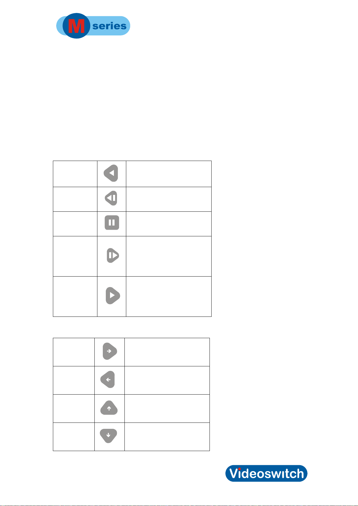
On a standard keypad, press one of the play keys to enter play mode:
Play_Back
Step_Back
Pause
Step_Forward
Play
On a mini-keypad, press one of the arrow keys (when not in menu):
Step back in playback mode
Step back in playback mode
Pause playback
Step forwards in playback
Play forward in playback
right
left
up
down
Play forwards
Go back in play mode
Go back in play mode
Pause in play mode
13
Page 20

Digital Recorder
14
Page 21

Digital Recorder
3 Navigation
3.1 Menus
• The menu system in this DVR allows many aspects of it operation to be customised to
suit a specific installation
• In the case of a Vi-M1 which has a mini-keypad, the root menu (accessed by pressing
SEL) takes the place of the dedicated functions keys on the standard keypad.
• The factory default settings that this unit is shipped with provide a standard
configuration that records all connected cameras continuously with a data retention
period of 31 days.
• The factory defaults may be restored at any time via the CONFIGURATION menu.
3.2 Mini-Keypad
When a mini-keypad is used (on a Vi-M1) the menu is always entered at its root level by
pressing the SEL key:
The required sub-menu may be selected using the up and down keys, pressing the SEL (or
right) key to enter it:
• Find
• Burn
• Menus
• Help
• Function
• Password
3.3 Standard Keypad
In the case of a standard keypad, dedicated function keys are provided to bypass the root
level of the menu and take you straight into the appropriate submenus:
15
Page 22
Digital Recorder
3.4 Summary of keys used in menus
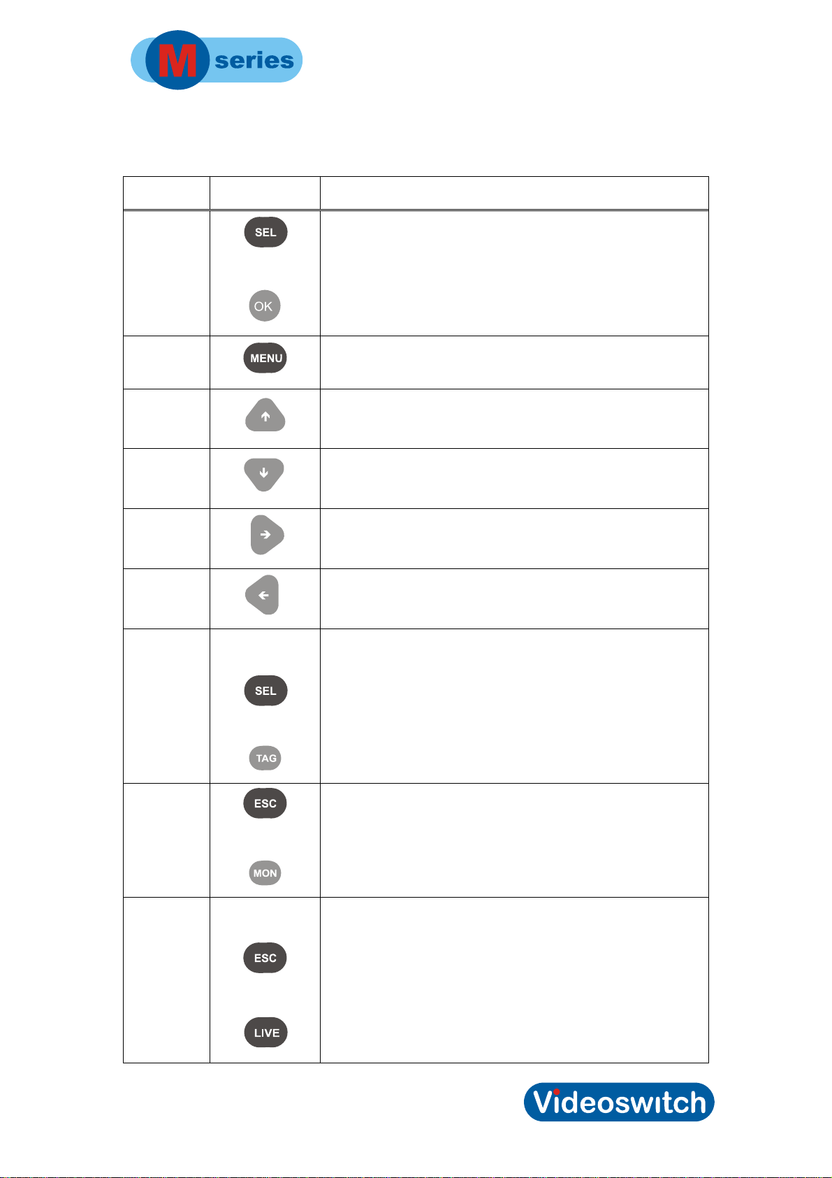
Key name Key legend Action
SEL
MENU
Up
Down
Right
Left
or
Press and hold
for 1 second
Enter the root of menu system, includes extra functions
(Mini-keypad). Selects an item for editing and also confirm
changes
Enter the menu system at menu level (Standard keypad)
Select the prior menu item or scroll a value when editing
Select the next menu item or scroll a value when editing
Go a level deeper into the menu or move cursor when
editing
Come out of a level in the menu or move cursor when
editing
DEFAULT
ESC
EXIT
or
or
Press and hold
for 1 second
or
Set the default setting of a menu item
Escape from a menu level or escape from editing a value
without saving
Leave menu completely. Any changes will be saved.
16
Page 23

Digital Recorder
17
Page 24

Digital Recorder
4 Find
• On a mini-keypad, Find is accessed by pressing SEL to enter the root menu, then
using up and down to select the required row, followed by SEL
• On a standard keypad, Find may be accessed directly by pressing the FIND key.
Press Find key again to switch between different find options.
4.1 Date/Time
• Use left and right to move the cursor
• Use up and down to scroll the digits
• A search will take place each time you change a digit and the image will be
displayed
• Press DEFAULT for the latest available image
• Press DEFAULT again for the earliest available image
4.2 Events
There are a number of event logs which store potentially large numbers of events. As you
scroll though these logs, the corresponding image is recalled and displayed on the screen.
1.1.4 Alarm
This log records alarm and activity events. It also logs Tag events which are manually
generated events.
1.1.5 System
This log record system events such as Ethernet access, log-ins and other normal system
activities.
1.1.6 Critical
This log record critical alerts which are error events. An example is a hard drive failure.
Events that have not been acknowledged are shown in red.
• Select the row using up, down, left and right
• Press SEL to cancel event
• If critical alert condition persists, another alert will be raised
• If there are a lot of critical alerts, they can all be cleared at once in the Alarms
menu
18
Page 25

Digital Recorder
5 Burn
• On a mini-keypad, Burn is accessed by pressing SEL to enter the root menu, then
using up and down to select the burn required row, followed by SEL. Press ESC to
return to menu.
• On a standard keypad, Burn may be accessed directly by pressing the BURN key.
Press BURN to switch between the incident edit and incident list
5.1 Edit Incident
This is an example of the edit incident screen.
• Use up and down to select rows
• Press SEL to start editing a row
• Use up, down, left, right or numbers to edit a row. Press DEFAULT to use current
play location in Start and End or to set a default incident in Duration of 4 minutes
• Press SEL to finish edit mode
Burn Edit incident 1
>Duration 0 Mins
Start Not Set
End Not Set
USB/CD CD
Erase Erase Not Required
Proceed Press OK
Incident/Total 0 Mb / 0 Mb Incidents
Free Space ----
To burn and incident
• Insert DVD,cd or USB memory stick.
• If media is incorrec t, move cursor to USB/CD row, press SEL, press up or down to
select media, press SEL to finish edit
• If media is to be erased prior to backup (no applicable with CD-R), move cursor to
Erase row, press SEL, press up or down to select erase, press SEL to finish edit
• Move cursor ro Proceed row
• Press SEL to enter edit mode
• Press up to select Yes
• Press SEL to start burn (backup) process
19
Page 26

Digital Recorder
5.2 Incident List
The incident list allows you to set up to 10 separate incidents (sections of video) which then
be backup up onto a CD or USB memory stick. If you do not want all the incidents, or the
total size is too large, you can selectively select or deselect incidents using the SEL key.
Only thos incidents that have a Y in the Sel column will be backed up to DVD/CD/USB.
This is an example of the incident list screen.
• Use up and down to select an incident
• Press SEL to toggle whether an incident is selected for burn
• Press Burn to switch back to the edit incident screen, or press ESC to return to
menu (when using a mini-keypad) so you can re-enter the edit incident screen.
Incident list Sel
>1 10/05/09 18:11:00>10/05/09 18:18:00 Y 99 Mb
2
3
4
5
6
7
8
9
10
Total Size 99 Mb
Free Space ----
Note that if you only ever burn individual incidents, you do not need to use the incident list
screen.
20
Page 27

Digital Recorder
6 Menus
• On a mini-keypad, Menus is access by pressing SEL to enter the root menu, then
using up and down to select the required row, followed by SEL
• On a standard keypad, Menus may be accessed directly by pressing the MENU key
Note that the menu items described in the following pages may differ slightly between
models depending on which features are available in that model and what level of firmware
is installed.
6.1 Date/Time
1.1.7 System date/time
Press SEL to start editing the date and time.
Enter the current date and time using the number keys.
Use the left and right keys to move between the digits as required if you do not want to re-
enter the whole date and time.
The normal format is DD/MM/YY HH:MM:SS.
Press SEL when you have finished editing the date and time, or press ESC to cancel.
It is essential for the correct operation of this DVR that the correct date and time is set in its
internal clock. All recorded images are date and time stamped so this information forms part
of the recorded evidence.
Battery backup ensures that the clock continues working even when power is removed for
short periods of time
Thel clock automatically moves forwards an hour during March and back an hour in October
for daylight saving. No adjustment by the user is required when the clocks change. The
times and dates suit most European countries.
1.1.8 Date format
Alternative date formats may be selected if required for display on the live and replay
screens:
• DD/MM/YY
• MM-DD-YY
• YY.MM.DD
21
Page 28

Digital Recorder
6.2 Record
1.1.9 Record settings
This screen allows you to set all the video record parameters.
To change a setting:
• Use up and down to move the pointer to the required row,
• Press SEL to enter edit mode (value goes red). The setting can then be changed
using up and down or number keys.
• Press SEL again to save the setting and get back the pointer. Alternatively, press
ESC if you want to escape from edit mode without changing the setting.
An example of the record screen is shown here:
Record Settings
> Mode Auto
Format 2CIF
Quality Medium
Auto retention 31 days
1-8 9-16
Custom rate per camera -- - Alarm rate per camera 25 25
Cameras fitted ################
Actual rate per camera 3.0 3.0
Average image size 3.3 Kb
Retention 72.0 days
1.1.1.3 Mode
The record mode may be set to these options:
• Auto The record image rate is calculated automatically such that the
video is retained for the number of days specified in the Auto
retention setting before being overwritten. The actual rate per
camera is shown so you can see what is being achieved. The rate
also depends on the hard disc capacity, the format and the quality
setting.
• Custom If this mode, the record image rate is determined by the Custom
rate per camera setting.
• Alarm In this mode, the DVR only records when there is an alarm. When
there is an alarm, it record at the rate specified by the Alarm rate
per camera setting
1.1.1.4 Format
The record format may be set as:
• CIF This is the lowest resolution, but offers maximum record rate of 25
pictures per second per camera. The record rate is fixed in this
mode at the maximum
• 2CIF This is an intermediate resolution and a good choice for most
situations. The maximum record rate is half that available in CIF
22
Page 29

Digital Recorder
mode.
• 4CIF This is the highest resolution (also known as D1) and provides the
maximum detail in the recorded images. Because it depends on two
interlaced fields, there can be interlacing artefacts displayed on
replay, particularly with fast moving subjects. The maximum record
rate is a quarter of that available in CIF mode.
1.1.1.5 Quality
As well as the resolution that is specified by the format, the degree of compression may be
set in the quality setting. This affects the level of detail recorded. The higher the quality, the
larger the image sizes and the slower the record rate for a given number of days image
retention.
1.1.1.6 Auto Retention
If Auto mode this option specifies the number of days that the DVR will be able to retain
video for before overwriting. Bear in mind that this is approximate, as the size of the
compressed video images depends on what the cameras are looking at. The software
continuously calculates the rate on the basis or hard disc capacity, image size, number of
cameras and requested number of days image retention.
1.1.1.7 Custom Rate per camera
If you have selected Custom mode, set the Custom rate per camera to the rate that you
require. The rate is set separately or each group of four cameras. Note that it is not possible
to set the rate of individual cameras.
The Actual rate per camera is shown and this may be lower than the requested (if the
specified rate is impossible). The estimated Retention is also shown so you can see if you
have specified a rate that results in a suitable number of days data retention.
1.1.1.8 Alarm rate per camera
The Alarm rate per camera is the rate at which the DVR attempts to record when an alarm
condition occurs. If a rate is specified that is not possible, the DVR will record as fast as it
can.
1.1.10 Record audio
Specify here whether you want to record audio or not. There will be a small benefit in disc
capacity if you do not require audio and turn this option off.
6.3 Display
1.1.11 Titles
Titles allow meaningful descriptions to be entered identify the DVR and the cameras.
1.1.1.9 Server
This text string describes the DVR or its location. This is useful when remotely accessing
the DVR via Ethernet as it confirms the identity of the DVR.
23
Page 30

Digital Recorder
• Use the left and right keys to move the cursor, and the up and down keys to select
the character.
• Use DEFAULT to erase the title completely or set back to Videoswitch
• When editing a title on a standard keypad, you can use the Inc and Dec keys to
insert and delete characters
1.1.1.10 Camera Titles
• The Plus and Minus keys on a standard keypad allow you to select predefined
titles when editing a camera title.
• Use the left and right keys to move the cursor
• Use the up and down keys to select the character.
• Use DEFAULT to erase the title completely or set back to Camera 1, Camera 2 etc.
• When editing a title on a standard keypad, you can use the Inc and Dec keys to
insert and delete characters
1.1.1.11 Show Camera Titles
You can choose how the cameras are identified on the main monitor in the various screen
formats. This can be useful to avoid cluttering the screen too much.
1.1.1.1.1 Full
Select whether you wish to identify the full screen camera by its number, by its title or not at
all. Note that the camera number of the currently selected monitor is always displayed in the
bottom right of the screen.
1.1.1.1.2 Quad
Select whether you wish to identify the QUAD cameras by number, by title or not at all.
1.1.1.1.3 x9
Select whether you wish to identify the 9-way multi-screen cameras by number, by title or
not at all.
1.1.1.1.4 x16
Select whether you wish to identify the 16-way multi-screen cameras by number, by title or
not at all.
1.1.1.12 Auto sequence (main monitor)
The cameras displayed on the main monitor may be sequenced automatically
1.1.1.1.5 Sequence Mode
Select whether you want random sequencing or normal sequen cing.
1.1.1.1.6 Camera List
Specify her which cameras you want to be included in the sequence.
• Use the left and right keys to move the cursor
24
Page 31

Digital Recorder
• Use the up and down keys to select (block) or deselect (dash) cameras
1.1.1.1.7 Dwell times
A separate auto-sequencing dwell time may be specified for each camera in this part of the
menu.
1.1.1.1.8 Dwell times (all)
An auto-sequencing dwell time may be specified for all cameras. This overrides the above
individual dwell time setting
1.1.1.13 Auto sequence (spot monitor)
The cameras displayed on the spot monitor(s) may be sequenced automatically
1.1.1.1.9 Spot1
1.1.1.1.10 Sequence Mode
Select whether you want random sequencing or normal sequen cing.
1.1.1.1.11 Camera List
Specify her which cameras you want to be included in the sequence.
• Use the left and right keys to move the cursor
• Use the up and down keys to select (block) or deselect (dash) cameras
1.1.1.1.12 Dwell times
A separate auto-sequencing dwell time may be specified for each camera in this part of the
menu.
1.1.1.1.13 Dwell times (all)
An auto-sequencing dwell time may be specified for all cameras. This overrides the above
individual dwell time setting .
1.1.1.14 Spot monitor options
1.1.1.1.14 Spot1
The spot monitor may be setup to automatically change camera or to change to autosequencing at different times of day.
6.3.1.1.1.1 Weekday spot daytime
Set the blocks on to indicate daytime hours during weekdays.
6.3.1.1.1.2 Weekend spot daytime
Set the blocks on to indicate daytime hours during weekends.
6.3.1.1.1.3 Day spot camera
This is the camera number that the spot monitor will display when the Spot Daytime starts,
or if the unit powers up in the daytime.
6.3.1.1.1.4 Day sequence spot
This option specifies whether the spot monitor will auto-sequence when the Spot Daytime
25
Page 32

Digital Recorder
starts, or if the unit powers up in the daytime.
6.3.1.1.1.5 Night spot camera
This is the camera number that the spot monitor will display when the Spot Daytime ends, or
if the unit powers up in the night-time.
6.3.1.1.1.6 Night sequence spot
This option specifies whether the spot monitor will auto-sequence when the Spot Daytime
ends, or if the unit powers up in the night-time.
1.1.1.15 Power-up options
1.1.1.1.15 Main monitor format
Following power-up the main monitor screen format can be set to Full, Quad, x9 multiscreen or x16 multi-screen.
6.3.1.1.1.7 Sequence main
Following power-up the main monitor may be set to auto-sequence.
6.3.1.1.1.8 Main camera
Specify the full screen camera that will be displayed on power-up.
6.4 Alarms
1.1.12 Alarm inputs
The following menu items deal with the alarm contact inputs.
1.1.1.16 Alarm polarities
Alarm contacts may be set as normally open or normally closed.
Note that if you select normally closed and nothing is connected to the alarm input, the
system will register an alarm.
1.1.1.17 Camera mapping
Normally Alarm1 maps to Camera 1, Alarm 2 maps to Camera2 etc.
The M-series DVRs support alarm mapping whereby each alarm input may be assigned to
any camera. Some cameras may therefore have multiple alarm inputs associated with them.
1.1.1.18 Alarm timers
The alarms may be programmed to be operative only during particular hours of the day.
These hours may be different for weekdays and weekends.
1.1.1.19 Weekday alarm times
Specify during which hours of each weekday the alarm inputs are active
1.1.1.20 Weekend alarm times
26
Page 33

Digital Recorder
Specify during which hours of the weekend the alarm inputs are active
1.1.1.21 Enable alarms all day
This menu option allows some or all cameras to have their alarms enabled all day,
irrespective of the Weekday and Weekend alarm time settings.
1.1.13 Activity
Activity (movement) detection may be set for all cameras. The following parameters should
be set:
• Zone Use DEFAULT to turn all zones on or off. Use the up, down, left
and right keys to move the cursor around turning zones on of off.
Press SEL to toggle whether sones rae being turned on or off.
• Level Press zero to bring control to this setting and enter a number 1-9 to
specify the sensitivity (9 is most sensitive)
• Spatial Press zero to bring control to this setting and enter a number 1-9 to
specify the spatial sensitivity Spatial sensitivity determines how
large an object has to be to be detected. A setting of 9 will be most
sensitive and will detect small objects.
1.1.1.22 Activity timers
Activity detection may be programmed to be operative only during particular hours of the
day. These hours may be different for weekdays and weekends.
1.1.1.23 Weekday activity times
Specify during which hours of each weekday activity detection is active
1.1.1.24 Weekend activity times
Specify during which hours of the weekend the alarm activity detection is active
1.1.1.25 Enable activity all day
This menu option allows some or all cameras to have their activity detection enabled all day,
irrespective of the Weekday and Weekend alarm time settings.
1.1.14 Critical alerts
1.1.1.1.16 Videloss
Specify here which cameras should be present. If any lose video, a critical alert will be
raised. Press DEFAULT to automatically set this to match the currently installed cameras.
1.1.1.1.17 Record stopped
Specify whether you want a critical alert to occur if record stops due to a disc or other fault.
1.1.1.1.18 Hard drives
Specify here which hard drives should be present. If a hard drive selected on this list fails, a
27
Page 34

Digital Recorder
critical alert will be generated.
1.1.15 Clear critical alerts
Critical alerts may be individually cleared (acknowledged) in the Critical alert event log. All
critical alert can be clear her at once.
1.1.16 Erase event list
The event logs can be erased here. Use with care as the events cannot be retrieved once
erased.
1.1.17 Pull-up and restore
This part of the menu deals with the pull-up of a camera on a monitor under alarm
conditions.
1.1.1.1.19 Pull-up monitor
Specify here on which monitor an alarm camera should be displayed.
1.1.1.1.20 Pull-up hold time
When an alarm condition occurs the associated camera is displayed for this hold time, even
if other cameras also have alarms meanwhile.
If other cameras have alarms these will then be displayed in turn, each one being shown for
the specified hold time.
1.1.1.1.21 Pull-up sequence time
When multiple alarmed cameras exist, once the hold time has elapsed for each, they will
start sequencing with a programmable sequence time.
1.1.1.1.22 Relay hold time
Whenever an alarm or activity event occurs, the alarm relay activates. When all alarm
conditions have cleared, the relay will stay activated until the relay hold time has expired.
When the record rate is modified by alarms, this condition will also apply until the alarm
relay deactivates.
1.1.1.1.23 Restore camera
Following the pull-up of one or more alarmed cameras, this setting determines whether the
original pre-alarm camera is restored, or whether the last alarmed camera is left on the
monitor.
1.1.18 Relay activation
1.1.1.26 Use relay1 for alarm
Relay 1 is normal is used to indicate that an alarm or activity state exists. Set this to False if
you want to use the relay for another purpose, for example remote control of lights etc.
28
Page 35

Digital Recorder
1.1.1.27 Use relay2 for critical alert
Relay 2 is normal is used to indicate that a critical alert has occurred. Set this to False if you
want to use the relay for another purpose, for example remote control of lights etc.
6.5 Network
Images from this DVR can be remotely viewed and menus accessed via:
• Local area network - connect to the Ethernet port.
• Broadband - connect a router to the Ethernet port.
1.1.19 IP address
If you wish to use the Ethernet port for local or Ethernet access, you need to give the DVR
an IP address.
If the DVR is on a network with other computer equipment, a compatible number should be
chosen. You may need to consult whoever is responsible for the network who can assign
you a number.
If you are connecting only to a broadband router, the default IP address should be
satisfactory. The router will also need setting. See our web site for details:
www.videoswitch.co.uk
1.1.20 Ports
1.1.1.28 Command
The DVR has a port dedicated for control. The default is 9221 (press DEFAULT). The ViViewer software that is used to view images remotely must specify this port in its setup. If a
router is used it must also be set up to suit. See our web site for details:
www.videoswitch.co.uk
1.1.1.29 Video
The DVR has a port dedicated for video. The default is 9222 (press DEFAULT). The ViViewer software that is used to view images remotely must specify this port in its setup . If a
router is used it must also be set up to suit. See our web site for details:
www.videoswitch.co.uk
1.1.21 Sub-net mask
Enter required subnet mask. Press DEFAULT for the default setting.
1.1.22 Gateway
29
Page 36

Digital Recorder
Enter required gateway. Press DEFAULT for the default setting.
1.1.23 MTU
The MTU may be set if necessary for compatibility with attached routers or computers.
Normally this option is set to zero which indicates automatic mode (press DEFAULT).
6.6 Configuration
1.1.24 Language
Specify the langue you require for the menus.
1.1.25 Unit number
If you wish to address multiple units from a single keyboard, make sure each DVR has a
different unit number. If multiple DVRS are cascaded, there must have unit number 1,2,3
etc.
1.1.26 Display
1.1.1.30 VGA resolution
If a VGA monitor is connected, set its native resolution here.
1.1.1.31 VGA gamma
Adjust this setting to get the best image
1.1.1.32 VGA motion
Adjust this setting to get the best image
1.1.1.33 Menu translucency
Menu may have either translucent or solid backgrounds. Set as preferred.
1.1.1.34 Boundary colour
The boundary or full screen and multi-0screen images may be set to off, black, dark grey,
light grey or white. Set as required.
1.1.27 Camera inputs
1.1.1.35 Termination
Specify here whether camera inputs should be terminated with 75ohms. Normally
30
Page 37

Digital Recorder
termination should be on.
1.1.28 Passwords
1.1.1.36 Logged off user
1.1.1.1.24 Access rights
Specify the access rights that are to be given when a user is not logged in.
1.1.1.37 Named users
1.1.1.1.25 User1..User4
6.6.1.1.1.1 Name
A user name may be specified here
6.6.1.1.1.2 Password
Specify the password (6 numbers)
6.6.1.1.1.3 Access rights
Specify the access rights that are to be given when a user is not logged in with this
password.
6.6.1.1.1.4 Login timeout
Specify the timeout period for this password. If no keypresses occur during this period, the
user will be automatically logged out.
1.1.29 Coverts
Covert cameras are cameras that are recorded but not normally displayed. If any cameras
are set to covert, they may only be viewed if a user is logged on with sufficient rights. He
also has to enable coverts in the Function menu.
1.1.1.38 Covert cameras (Main)
Specify here which cameras are to be covert (hidden) on the main monitor.
1.1.1.39 Covert cameras (Spot1)
Specify here which cameras are to be covert (hidden) on spot 1 monitor.
1.1.30 Restore factory defaults
Restore all menu settings to the factory defaults.
1.1.31 Restart the system
31
Page 38

Digital Recorder
Restart the system. This is equivalent to power-cycling the DVR and may occasionally be
required following software upgrades.
32
Page 39

Digital Recorder
7 Help
• On a mini-keypad, Help is access by pressing SEL to enter the root menu, then
using up and down to select the required row, followed by SEL
• On a standard keypad, Help may be accessed directly by pressing the HELP key
7.1 Status/Config
1.1.32 Config
This is an example of the config screen, which shows the configuration of the DVR.
Press left or right to see other help screens.
Config
Model Vi-M316 (16 cameras)
Cards fitted CM- C-- CM- C-- ---
Capacity 992 Gbytes
Serial number 00298350
Firmware ID 1818
Logic ID 7
Unit number None
IP address 192.168.16.67
MAC address 00:00:49:09:1A:DC
Ethernet 100 Mb/s HDX
1.1.33 Status
This is an example of the status screen which shows the status of video, alarms, activity
etc.
Press left or right to see other help screens.
Status
Video ################
Alarms ----------------
Activity ----------------
Relay timer ----------------
Relays --
Load [= ]
Temperature 49C
MMC status OK
33
Page 40

Digital Recorder
1.1.34 Drives
This is an example of the drives screen which shows a summary of all the fitted drives.
Press left or right to see other help screens.
Drives
HD1 496 GBytes SMART OK Recording
HD2 496 GBytes SMART OK
DVD1 No media
1.1.35 Drive1
This is an example of the Drive 1 screen which shows details of this particular drive. Similar
screens exist for each drive.
Press left or right to see other help screens.
Drive 1
Name HD1
Capacity 496 GBytes
Model WDC WD5000AVVS-63H0B1
Ser No WD-WCAUH00431
SMART SMART OK
State Recording
Earliest 05/05/09 12:19:00
Latest 10/05/09 17:49:00
34
Page 41

Digital Recorder
1.1.36 Record
This is an example of the record status screen which shows details of the current record
parameters.
Press left or right to see other help screens.
Record
Current record mode Auto
Record rate 48/100 pps (2CIF)
Cameras ################
Average image size 3.1 Kb
Rate per camera (1-8) 3.0 pps
Rate per camera (9-16) 3.0 pps
Image retention 76.0 days
Earliest 05/05/09 12:19:00
Latest 10/05/09 17:52:50
35
Page 42

Digital Recorder
8 Function
• On a mini-keypad, Function is access by pressing SEL to enter the root menu,
then using up and down to select the required row, followed by SEL
• On a standard keypad, Function may be accessed directly by pressing the FN key
Functions are used to alter temporary settings such as auto-sequencing or relay status.
• Press up, down, left and right to select a function (or type in a number)
• Press SEL to toggle the state or action the function
36
Page 43

Digital Recorder
9 Password
• On a mini-keypad, Password is access by p ressing SEL to enter the root menu,
then using up and down to select the required row, followed by SEL
• On a standard keypad, Password may be accessed directly by pressing the PSW
key
• Type in a password,, comprising up to 6 numbers
• Press SEL
• If the password matches one of those set in the menu, a message will report that
you are logged in. Press SEL with no password (or zero) to log out
37
Page 44
Digital Recorder
10 Connections
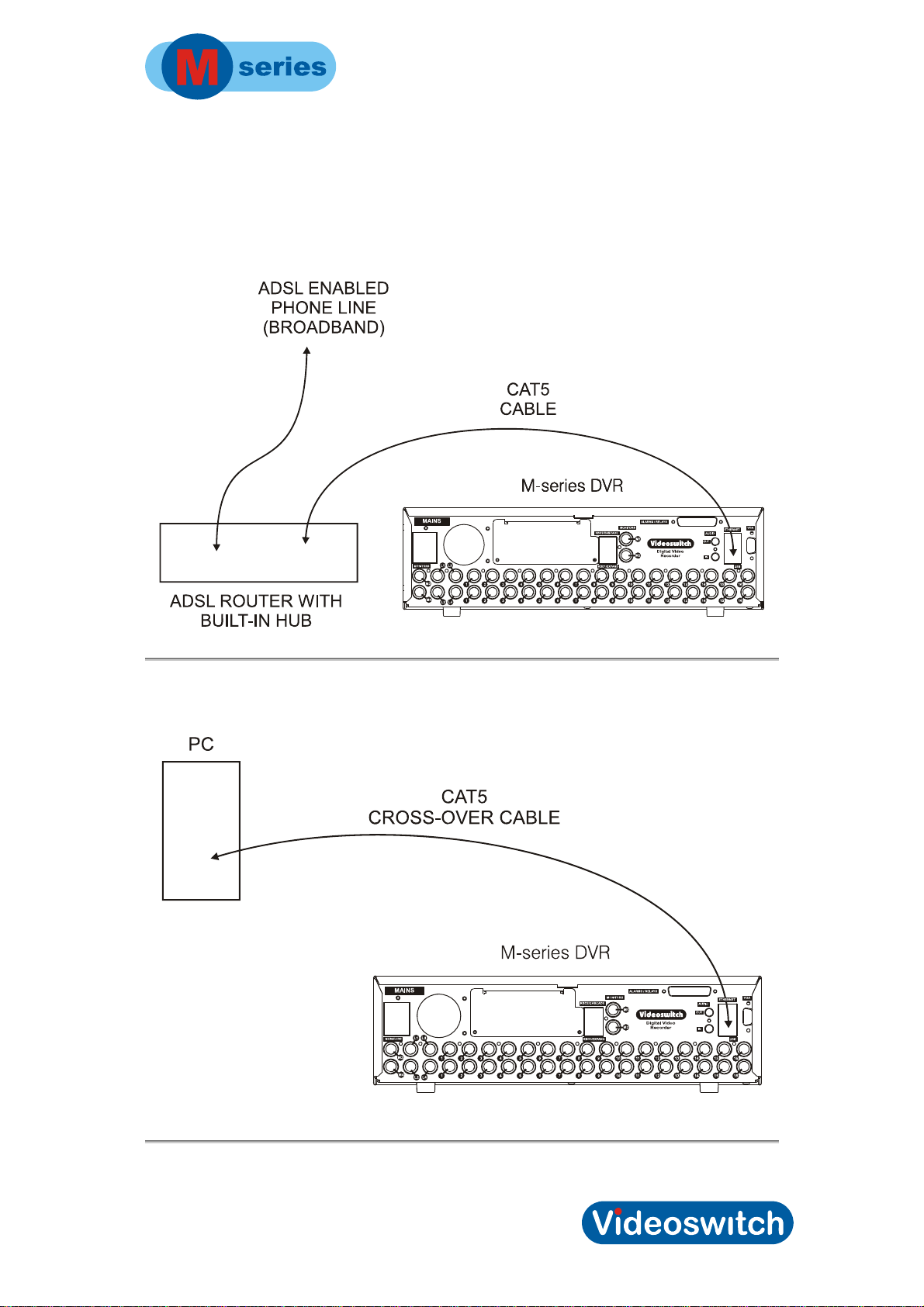
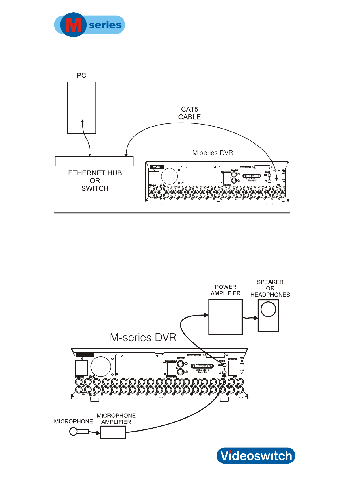
10.1 Ethernet connection to Broadband
10.2 Ethernet connection to a PC
38
Page 45
Digital Recorder
10.3 Ethernet connection to a LAN
10.4 Audio
• Connect a microphone via a microphone amplifier to the LINE input.
• The LINE output is used to drive either a speaker with a built-in amplifier or a
separate amplifier and speaker.
39
Page 46
Digital Recorder
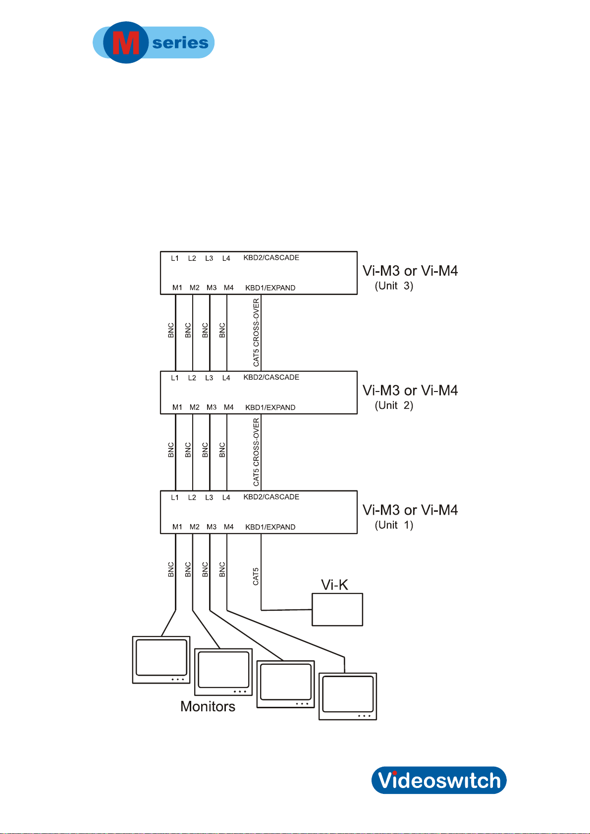
10.5 Multi Unit Cascading
Up to 16 M-series DVRs can be cascaded to cater for up to 256 cameras. Built-in matrix
switching allows eny DVR to display on any monitor. Cameras are selected by entering 1 to
256 on the Vi-K1, Vi-K2 or Vi-K3 keyboard.
Note: check with Videoswitch technical support that you have a firmware version that
supports this feature.
This diagram shows how three units may be cascaded. Further units may be added in the
same manner:
40
Page 47

Digital Recorder
11 Technical Data
11.1 Accessories Included
• M-series DVR
• Mains Cable
• External PSU (in case of Vi-M1)
• Vi-X16 Alarm Break-out module (Vi-M3, Vi-M4)
• Vi-X17 Relay/Dome Break-out Module (Vi-M1, Vi-M2)
• Hard Drive Keys (x2)
• Manual
• CAT5 Ethernet Cable
• Blank CDs
11.2 Changing the Hard Drive
Hard drives are sensitive mechanical devices that may be damaged by shock or vibration.
Always protect them from shock and vibration when transporting and do not move them
within 30 seconds of being powered up.
Remove power from the M-series DVR before removing the hard drive.
seconds for the drive to stop spinning before moving the DVR or removing the hard
drive. Moving a drive that is still spinning can damage it.
1.1.37 Changing a hard drive - Vi-M1
• Remove power from the DVR
• Unlock the cover of the DVR using the key supplied with the DVR. Insert the key,
and turn it anti-clockwise to unlock the cover
• Slide the cover back about 6mm millimetres to disengage the tabs at the rear and
the front
• Lift of the whole cover so the inside of the DVR is exposed
• Unscrew the thumb screws on the hard drive taking care not to damage any of the
parts within the DVR
Wait for 30
• Remove the hard drive
• Replace the hard drive and tighten the two thumb screws to secure it
• Replace the cover approximately 6mm back from its fully closed position
• Turn the key clockwise to lock the cover, pushing it forwards at the same time
• R-apply power to the DVR and wait for it to re-boot
• If the drive has not been pre-formatted, you will be asked if you want to format it.
41
Page 48

Digital Recorder
Press SEL to confirm and wait approximately 15 minutes before the DVR is able to
start recording. It may up to 1hour per Tbyte to completely format the drives. See
Drive1 information screen to monitor progress.
1.1.38 Changing a hard drive - Vi-M2/Vi-M3/Vi-M4
• Remove power from the DVR
• The hard drive bay requires a special key to unlock it. This is supplied with the M-
series DVR. Insert the key, and turn it clockwise to unlock the drive.
• Hinge open the door to the drive bay and remove it completely, taking care not to
damage the fans or other parts
• Locate the drive you wish to remove: Hard drive 1 is the upper one and Hard drive 2
is the lower one
• Pull the metal tab on the metal plate under the hard drive to be removed and slide
out the drive. Take care the drive does not fall out as it is only retained by a hinged
bracket
• Open the hinged bracket so that the hard drive can be removed
• Put the new drive onto the plate and close the hinged bracket so that the drive is
located by all four tabs
• Slide the plate back into the bay, taking care that it lines up correctly with the correct
slot. Note that the bay is tapered, so it starts a loose fit and gets snug as it is
pushed fully home.
• Change the other drive if required in the same way
• Locate the tabs on the bay door into the corresponding holes on the right side of the
drive bay.
• Hinge the door closed, making sure the key is in the unlocked position and that the
connector engages with its mating half.
• Turn the key anti-clockwise to lock the door
• R-apply power to the DVR and wait for it to re-boot
• If the drive has not been pre-formatted, you will be asked if you want to format it.
Press SEL to confirm and wait approximately 15 minutes before the DVR is able to
start recording. It may up to 1hour per Tbyte to completely format the drives. See
Drive1 and Drive 2 information screen to monitor progress.
42
Page 49
Digital Recorder
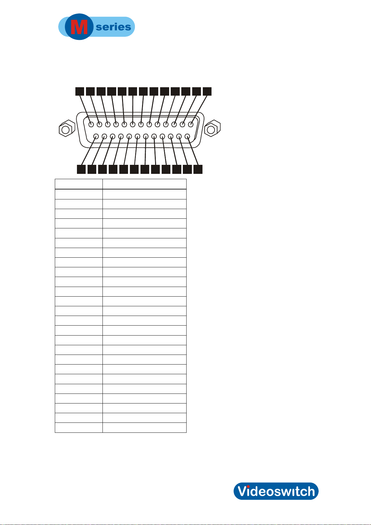
Connector Pin-Outs
1.1.39 Alarms, Domes, Relays
14
123
4
5
6
7
8
9
10
111213
15
16
17
18
19
20
2122242425
Pin Number Signal
1 Alarm Input 1
2 Alarm Input 2
3 Alarm Input 3
4 Alarm Input 4
5 Alarm Input 5
6 Alarm Input 6
7 Alarm Input 7
8 Alarm Input 7
9 Alarm Input 8
10 Alarm Input 10
11 Alarm Input 11
12 Alarm Input 12
13 Alarm Input 13
14 Alarm Input 14
15 Alarm Input 15
16 Alarm Input 16
17 Spare
18 +9V output
19 Dome 1 output: RS485 + (A)
20 Dome 1 output: RS485 – (B)
21 Dome 2 output: RS485 + (A)
22 Dome 2 output: RS485 – (B)
23 Relay 2 output, normally open
24 Relay 1 output, normally open
25 Alarm Common (GND)
Note: The Vi-X16 or Vi-X17 breakout adaptors supplied with the Vi-M1, Vi-M2, Vi-M3 and
Vi-M4 provide a convenient means of making connection to the alarm, dome and relay
signals via screw terminals.
43
Page 50
Digital Recorder
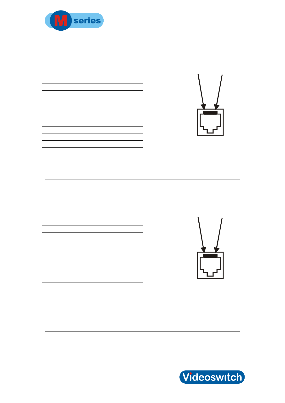
1.1.40 Main Keyboard Port
Physical: RJ45 (lower connector)
Electrical: RS485
Pin Number Signal
1 RS485 Input+ (A)
2 RS485 Input- (B)
3 RS485 Output+ (A)
4 +9V output for Keyboard
5 GND
6 RS485 Output- (B)
7 Twisted-Pair Video+
8 Twisted-Pair Video-
Note:
A standard CAT5 patch cable may be used to connect the M-series DVR to the optional Vi-
K1, Vi-K2 or Vi-K3 keyboard.
PIN1 PIN8
1.1.41 Spot Keyboard/Cascade Port
Physical: RJ45 (upper connector)
Electrical: RS485
Pin Number Signal
1 RS485 Input+ (A)
2 RS485 Input- (B)
3 RS485 Output+ (A)
4 +9V output for Keyboard
5 GND
6 RS485 Output- (B)
7 Twisted-Pair Video+
8 Twisted-Pair Video-
Note:
A standard CAT5 patch cable may be used to connect the M-series DVR to the optional Vi-
K1, Vi-K2 or Vi-K3 keyboard.
This port may be configured as a cascade port for linking to the Main keyboard port of
another DVR. In this case a CAT5 cross-over cable is used.
PIN1 PIN8
44
Page 51

Digital Recorder
11.3 Specifications
1.1.42 Storage
Hard drives SATA interface. 250 Gbytes to 2 Tbytes (and more as larger
drives are developed)
Number of hard drives Vi-M1: 1 hard drive, Vi-M2, Vi-M3, Vi-M4: 2 hard drives
CD/DVD writer Backup to DVD or CD. Play without installing viewer. CD
may also be used to upgrade firmware.
USB Backup to USB memory stick. Play without installing viewer.
1.1.43 Digital recording/Replay
Camera inputs 4, 8, 12 or 16, with programmable titles (16 characters)
Image Retention 1 to 999 days, image rate calculated automatically (custom
mode allows rate to be specified)
Colour/Monochrome Auto sense
Gain, Brightness, Colour Auto
Record Resolution CIF: 352 x 288 pixels x 16.8 million colours
2CIF: 704 x 288 pixels x 16.8 million colours
4CIF: 704 x 576 pixels x 16.8 million colours
Image size 6k to 40k bytes, dynamically variable, typically 8K for CIF
Compression method MPEG4
Hardware/Software Embedded processor, Linux, proprietary Videoswitch
software
Simultaneous processing Record, Live, Play, Remote and backup
Image authentication Each image is tagged with time, date, image number and
other information and is protected with a digital security
signature for authentication.
Video inputs 0.5 to 1V pk-pk, 75 Ohms (switch able via menu),
composite PAL (BNC), all inputs have loop-through BNCs
Loop-though BNC connectors On Vi-M3 and Vi-M4
Maximum record rate 100 CIF pictures per second (Vi-M1)
200 CIF pictures per second (Vi-M2 and Vi-M3)
400 CIF pictures per second (Vi-M4)
1.1.44 Display
Main monitor output (a) Composite (BNC), 1V pk-pk composite PAL
(b) VGA monitor output
Spot monitor outputs BNC, 1V pk-pk composite PAL
45
Page 52

Digital Recorder
Main monitor display modes Full screen, quad, 9-way and 16-way split (16 camera
models only)
Auto Sequencing 1-99 seconds, full and quad, main and spot monitors
Covert (hidden) any cameras may be hidden from view on the monitors
1.1.45 Control and Interface
Standard Keypad 35 single function keys (Vi-M2, Vi-M3 and Vi-M4)
Mini Keypad 14 single and 2 dual function keys (Vi-M1)
Remote keyboard Inputs RJ45, RS485 , 9600-baud (1 start, 8 data, 1 stop) data, with
built-in balun for twisted pair video connection to remote
keyboards with attached monitors.
Spot monitors 4 camera models – no spot monitor output is available
8 camera models – 1 spot monitor
12 camera models – 2 spot monitors
16 camera models – 3 spot monitors
Passwords 4 passwords with fully programma ble rights. Also
programmable rights when not logged on.
Search modes Date/time search, sweep, alarm, system and cricical event
log
Timers Alarm and activity (by hour for weekdays and weekend)
Audio Dual channel audio, 8kHz bandwidth
Line input/output 3.5mm stereo jack connectors, -30dB level, 47k Ohms
Audio sensitivity control 30db range, via menu
Alarm inputs 16 inputs, suit normally open or normally closed volt-free
contacts, inputs mapped
Activity detection 16 x 12 zones, programmable sensitivity
Relays 2 relays
Relay Contact Rating: 24Vdc, 200mA max normally open or closed
Alarm/activity response Pull-up full screen display, maximum record rate
Events logs Alarms, System, Critical
Incident list Up to 10 incidents may be saved onto one DVD, CD or USB
memory stick
Watchdog timer In the event of any unexpected condition, the system will
automatically restart
1.1.1.40 Dome Control
Interfaces RS485 (x2), Up-the-Coax (x16)
Telemetry (coax) BBV
Telemetry (twisted pair) RS485, RS232 and 20mA. Protocols include Videoswitch
VXP-4, JVC, VCL, BBV, Dennard, Sanyo, Samsung,
Forward Vision, Mercer, Molynx/Bewator, Merit-LiLin,
Borsatec, Pelco-D
46
Page 53

Digital Recorder
1.1.1.41 Remote Viewing
Ethernet 100baseT, TCP/IP, suitable for connection to broadband
router or LAN. Software supplied.
Ethernet bandwidth Depends on record rate, image size, number of images
being viewed and number of connections. Typically in the
range 2Mbits/sec to 10Mbits/sec.
Remote viewing software Vi-Viewer or Vi-ViewerPro may be used on a PC running
Windows 2000, Windows XP or Windows Vista
47
Page 54

Digital Recorder
1.1.46 Power, Physical & Environmental
Mains Power input 90-135 Vac 2 Amps or 180-265 Vac 1 Amp, 47-63Hz
Temperature 5 to 35deg C (operating), -10 to 40deg C (storage)
Humidity 5 to 95% non-condensing
Vi-M1
Dimensions/Weight (Unit) 180mm x 65mm x 330mm (WxHxD), 3kg
Dimensions/Weight (Boxed) 275mm x 380mm x 475mm (WxHxD), 5kg
Vi-M2
Dimensions/Weight (Unit) 165mm x 200mm x 330mm (WxHxD), 6kg
Dimensions/Weight (Boxed) 275mm x 380mm x 475mm (WxHxD), 8kg
Vi-M3, Vi-M4
Dimensions/Weight (Unit) 355mm x 100mm x 390mm (WxHxD), 7kg
Dimensions/Weight (Boxed) 480mm x 295mm x 580mm (WxHxD), 9kg
1.1.47 Upgrades
Remote viewing Software Remote viewing software (Vi-Viewer) is available on the
Internet:
It is also copied onto the CD/DVD or USB device each time
incidents are written.
Firmware upgrades Firmware upgrades will be made available on CD and the
Internet (free of charge)
Camera Upgrades If you have fewer than the maximum possible camera inputs
for the model, an upgrade modules may be purchased to
enable the other inputs.
Hard Drive Upgrades Hard drives are available to increase the drive capacity or
for replacement in case of drive failure.
www.videoswitch.co.uk.
48
Page 55

Digital Recorder
1.1.48 CE Marking
This product is CE marked. It has been fully tested and complies with 89/336/EEC
Electromagnetic Compatibility and 73/23/EEC Low Voltage directives, and with EN
60950:2000 safety standards.
Warning: This is a Class A product. In a domestic environment this product may cause
radio interference in which case the user may be required to take adequate measures.
1.1.49 Ventilation
The M-series DVR Digital Recorder has ventilation holes in the base, front and rear. Using
internal fans, the unit creates a continuous flow of air through the unit to control the
temperature of the disc drives and other internal components.
The ventilation holes must not be obstructed otherwise the lifetime and reliability of the
system may be affected.
1.1.50 Safety
For warranty and safety reasons, the cover of this equipment must not be removed. There
are no user serviceable parts inside.
49
Page 56

Digital Recorder
Serial Number of M-series DVR
Notes
Notes
50
Page 57
Digital Recorder
12 Warranty Fax-Back
Please fill-in and fax or post this form (or a copy) back to Videoswitch. This will enable us
you to inform you of free upgrades when they become available.
Serial Number of M-series DVR
(This is on the label under DVR and
also in the config help screen)
Your Name
Company Name
Address & Email
Date Purchased
Purchased From
Fax to:
01252-851296
Or Send to:
Videoswitch, Ocean House, Redfields Industrial Park, Redfields Lane
Church Crookham, Fleet, Hants GU52 0RD
51
Page 58

Page 59

 Loading...