

Videoswitch Vi-R4000 User Manual
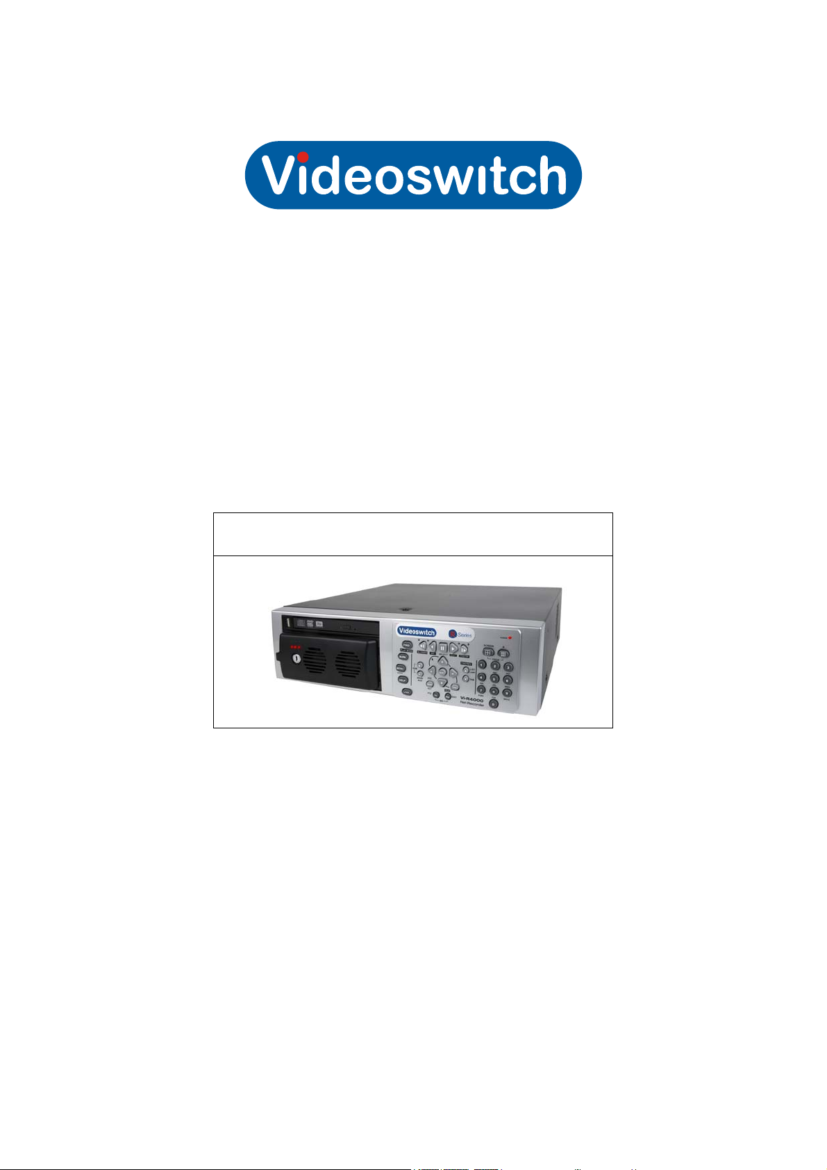
Vi-R4000 Series Net Recorder
User Manual
Products covered by this manual
Vi-R4005, Vi-R4105, Vi-R4205
Document Reference Date Firmware
Mdr602a.doc 06/06/2013 From V2.2.2 Build 121220, Interface:174
Videoswitch
Ocean House, Redfields Industrial Park
Redfields Lane, Church Crookham
Hants GU52 0RD
Videoswitch Mdr602a.doc
Telephone
Fax
Email
Web
01252-851510
01252-851296
sales@videoswitch.co.uk
www.videoswitch.co.uk

Videoswitch Mdr602a.doc

Vi-R4000 Series
Contents
1 Getting Started.......................................1
1.1 Monitors .................................................................................................................................2
1.1.1 VGA Monitor ......................................................................................................................2
1.1.2 HDMI / DVI Monitor............................................................................................................2
1.1.3 BNC Monitors.....................................................................................................................2
1.2 Control....................................................................................................................................3
1.2.1 Keyboard Control ............................................................................................................... 3
1.2.2 Mouse Control....................................................................................................................5
1.2.3 Mouse Emulator Control ....................................................................................................5
1.2.4 External Keyboards............................................................................................................5
1.3 Cascading .............................................................................................................................. 6
2 Installation..............................................7
2.1 Preventive and Cautionary Tips.............................................................................................8
2.2 Rear Panel Connections ........................................................................................................ 9
2.2.1 Essential Connections .......................................................................................................9
2.2.2 Optional Connections.........................................................................................................9
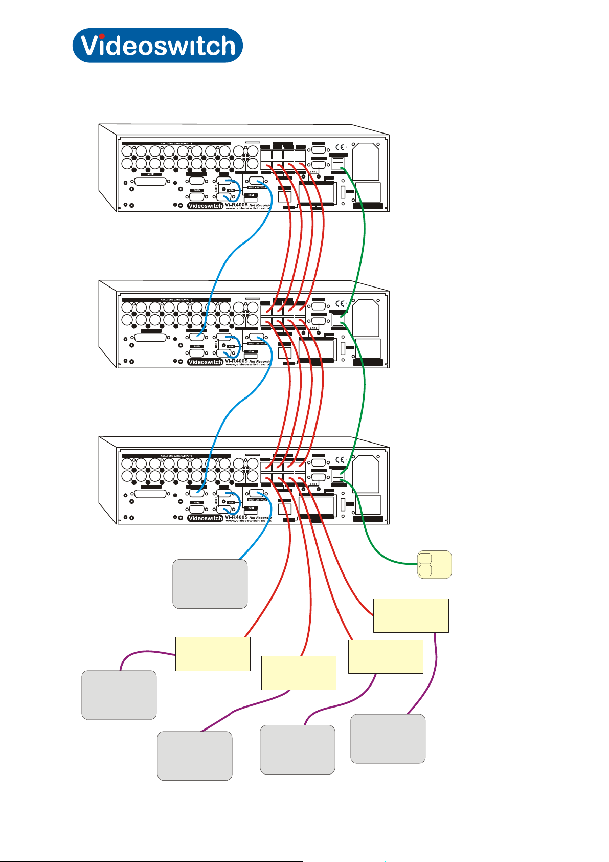
2.2.3 Connecting for Cascade Operation..................................................................................10
2.3 Replacing a Hard Drive........................................................................................................11
3 Commissioning....................................12
3.1 Password Access................................................................................................................. 13
3.1.1 Keyboard Mode................................................................................................................13
3.1.2 Mouse ..............................................................................................................................13
3.1.3 Mouse Emulator Mode.....................................................................................................13
3.1.4 Default Passwords ...........................................................................................................13
3.2 Default Configuration ...........................................................................................................15
3.2.1 System Configuration.......................................................................................................15
3.2.2 Interface Configuration.....................................................................................................15
3.2.2.1 Unlock Interface Settings............................................................................................ 15
3.2.2.2 Lock Interface Settings ............................................................................................... 15
3.2.2.3 Display Interface Firmware Revision .......................................................................... 15
3.2.2.4 Default all Interface Settings....................................................................................... 15
3.2.2.5 Summary of commands.............................................................................................. 16
3.3 Record Settings ...................................................................................................................19
3.3.1 Schedule ..........................................................................................................................19
3.3.2 Resolution ........................................................................................................................19
3.3.3 Quality..............................................................................................................................20
3.3.4 Frame Rate ......................................................................................................................20
3.3.5 Max Bitrate.......................................................................................................................20
3.3.6 Copy settings to all other Cameras..................................................................................20
3.3.7 Retention Period ..............................................................................................................22
3.3.8 Retention Period Tables ..................................................................................................22
3.3.8.1 16 Camera Systems ................................................................................................... 23
3.3.8.1.1 Retention Period for 1Tbyte, 16 cameras 23
3.3.8.1.2 Retention Period for 2Tbyte, 16 cameras 23
3.3.8.1.3 Retention Period for 4Tbyte, 16 cameras 24
3.3.8.1.4 Retention Period for 8Tbyte, 16 cameras 24
3.3.8.2 12 Camera Systems ................................................................................................... 25
3.3.8.2.1 Retention Period for 1Tbyte, 12 cameras 25
Videoswitch Mdr602a.doc

Vi-R4000 Series
3.3.8.2.2 Retention Period for 2Tbyte, 12 cameras 25
3.3.8.2.3 Retention Period for 4Tbyte, 12 cameras 26
3.3.8.2.4 Retention Period for 8Tbyte, 12 cameras 26
3.3.8.3 8 Camera Systems .....................................................................................................27
3.3.8.3.1 Retention Period for 1Tbyte, 8 cameras 27
3.3.8.3.2 Retention Period for 2Tbyte, 8 cameras 27
3.3.8.3.3 Retention Period for 4Tbyte, 8 cameras 28
3.3.8.3.4 Retention Period for 8Tbyte, 8 cameras 28
3.3.8.4 4 Camera Systems .....................................................................................................29
3.3.8.4.1 Retention Period for 1Tbyte, 4 cameras 29
3.3.8.4.2 Retention Period for 2Tbyte, 4 cameras 29
3.3.8.4.3 Retention Period for 4Tbyte, 4 cameras 30
3.3.8.4.4 Retention Period for 8Tbyte, 4 cameras 30
3.3.9 Retention Period Calculator .............................................................................................31
3.4 Casacading .......................................................................................................................... 32
3.4.1 Vi-R4000 Recorders (address range 2) ........................................................................... 32
3.4.2 Vi-R4000 Recorders (address range 1) ........................................................................... 33
3.4.3 Vi405 and Vi-R4000 Recorders (address range 1)..........................................................34
3.4.3.1 Manually Set DVR Address ........................................................................................35
3.4.3.2 Manually Set Address Range ..................................................................................... 35
3.4.4 Sharing a VGA Monitor ....................................................................................................35
3.5 Termination .......................................................................................................................... 36
3.5.1 Turn Camera Termination ON .........................................................................................36
3.5.2 Turn Camera Termination OFF........................................................................................ 36
3.6 Auto-Sequencing .................................................................................................................37
3.6.1 Auto-Switch......................................................................................................................37
3.6.2 Start/Stop Auto-Switching ................................................................................................37
3.6.3 Auto-Sequencing .............................................................................................................37
3.6.4 Auto-Sequencing across Cascaded Units .......................................................................37
3.6.5 Start/Stop Auto-sequencing .............................................................................................38
3.7 Covert Cameras ...................................................................................................................39
3.7.1 Main Monitor (Monitor 1)..................................................................................................39
3.7.1.1 Set Covert................................................................................................................... 39
3.7.1.2 Clear Covert................................................................................................................39
3.7.2 Monitor 2 .......................................................................................................................... 39
3.7.2.1 Set Covert................................................................................................................... 39
3.7.2.2 Clear Covert................................................................................................................39
3.7.3 Monitor 3 .......................................................................................................................... 40
3.7.3.1 Set Covert Camera .....................................................................................................40
3.7.3.2 Clear Covert Camera..................................................................................................40
3.7.4 Monitor 4 .......................................................................................................................... 40
3.7.4.1 Set Covert Camera .....................................................................................................40
3.7.4.2 Clear Covert Camera..................................................................................................40
3.7.5 Video export and Remote View .......................................................................................40
3.8 PTZ Control.......................................................................................................................... 41
3.8.1 Up-the-coax .....................................................................................................................41
3.8.1.1 Disable PTZ Control ...................................................................................................41
3.8.1.2 Enable Coax Control...................................................................................................41
3.8.1.3 Set Coax Transmission Timeout.................................................................................41
3.8.2 Connecting up Domes for RS485 Control........................................................................ 42
3.8.3 Connection for dome control via menu or ethernet..........................................................42
Videoswitch Mdr602a.doc

Vi-R4000 Series
3.8.4 RS485 Local Control using DVR Protocols......................................................................43
3.8.4.1 Enable RS485 Control on outputs 1 & 2..................................................................... 43
3.8.4.2 Enable RS485 Control on outputs 3 & 4..................................................................... 43
3.8.4.3 Set RS485 Protocol for Outputs 1 & 2 ........................................................................43
3.8.4.4 Set RS485 Protocol for Outputs 3 & 4 ........................................................................43
3.8.5 RS485 Protocols .............................................................................................................. 18
3.8.6 RS485 Local Control using Keyboard Protocols..............................................................44
3.8.7 RS485 Dome Control via Menu .......................................................................................44
3.8.8 RS485 Dome Control via Ethernet...................................................................................44
4 User.......................................................45
4.1 Live Viewing.........................................................................................................................46
4.1.1 Full screen .......................................................................................................................46
4.1.2 Multi-Screen.....................................................................................................................46
4.1.3 Auto-Switching ................................................................................................................. 46
4.1.4 Auto-Sequencing .............................................................................................................46
4.1.5 Main or Aux Monitor Selection ......................................................................................... 46
4.1.6 Screen Warning Symbols ................................................................................................46
4.1.6.1 Yellow Triangle ........................................................................................................... 47
4.1.6.2 Red Cross...................................................................................................................47
4.1.7 Quick setting Toolbar .......................................................................................................47
4.2 Spot Monitors.......................................................................................................................48
4.2.1 Using Vi-K1 remote keyboard .......................................................................................... 48
4.2.2 Using Vi-K1 to control other monitors ..............................................................................48
4.2.3 Using Vi-K2(A) remote keyboard .....................................................................................48
4.3 Play ...................................................................................................................................... 49
4.4 Video Export.........................................................................................................................50
4.5 Remote Viewing...................................................................................................................51
4.5.1 Browser............................................................................................................................51
4.5.2 Vi-Viewer4000 Camera Management System.................................................................51
5 Reference .............................................52
5.1 Menu .................................................................................................................................... 53
5.1.1 Playback ..........................................................................................................................53
5.1.2 Recording Configuration ..................................................................................................53
5.1.2.1 Quick Schedule...........................................................................................................53
5.1.2.2 Advanced Schedule Configuration .............................................................................53
5.1.2.3 Record Quality Settings ..............................................................................................53
5.1.2.4 Motion Detection Settings........................................................................................... 53
5.1.2.5 Trigger Settings ..........................................................................................................53
5.1.3 Cameras Setup ................................................................................................................ 53
5.1.3.1 Privacy Zones .............................................................................................................53
5.1.3.2 Video Tampering Detection ........................................................................................ 53
5.1.3.3 Video Loss Detection.................................................................................................. 53
5.1.3.4 OSD Configuration......................................................................................................53
5.1.4 Status...............................................................................................................................53
5.1.4.1 Drive Information ........................................................................................................53
5.1.4.2 Chan Status ................................................................................................................53
5.1.4.3 Record Status .............................................................................................................53
5.1.4.4 Alarm Status ...............................................................................................................53
5.1.4.5 Network Status ...........................................................................................................53
5.1.4.6 HD Status ...................................................................................................................53
Videoswitch Mdr602a.doc

Vi-R4000 Series
5.1.5 System Configuration.......................................................................................................53
5.1.5.1 Time/Date ...................................................................................................................53
5.1.5.2 Network.......................................................................................................................53
5.1.5.3 PTZ .............................................................................................................................54
5.1.5.4 Serial Settings.............................................................................................................54
5.1.5.5 On Camera Settings ...................................................................................................54
5.1.5.6 Exception ....................................................................................................................54
5.1.5.7 Display ........................................................................................................................54
5.1.5.8 Disk Management....................................................................................................... 54
5.1.5.9 Email........................................................................................................................... 54
5.1.6 File Management .............................................................................................................54
5.1.7 Maintenance ....................................................................................................................54
5.1.7.1 Firmware Upgrade ......................................................................................................54
5.1.7.2 Factory Default ...........................................................................................................54
5.1.7.3 Shutdown.................................................................................................................... 54
5.1.7.4 Configuration Export/Import........................................................................................54
5.1.7.5 System Logs ...............................................................................................................54
5.2 Connector Pin-outs ..............................................................................................................55
5.2.1 Domes..............................................................................................................................55
5.2.2 Control .............................................................................................................................55
5.2.3 Keyboards........................................................................................................................56
5.2.4 Cascade...........................................................................................................................56
5.2.5 56
5.2.6 VGA .................................................................................................................................57
5.2.7 Audio................................................................................................................................58
5.3 Specifications.......................................................................................................................59
5.3.1 Video................................................................................................................................59
5.3.2 Audio................................................................................................................................59
5.3.3 Recording.........................................................................................................................59
5.3.4 Playback ..........................................................................................................................59
5.3.5 Storage ............................................................................................................................59
5.3.6 Network............................................................................................................................60
5.3.7 Interface ........................................................................................................................... 60
5.3.8 Power...............................................................................................................................60
5.3.9 Environmental .................................................................................................................. 60
5.3.10 Dimensions & Weight.......................................................................................................60
Videoswitch Mdr602a.doc

Vi-R4000 Series
1 Getting Started
Videoswitch Page 1 Mdr602a.doc
Vi-R4000 Series
1.1 Monitors
The DVR can provide the follow output screens:
• Main This is used for full-screen or multi-screen live, play and configuration
• Aux This is used for full-screen or multi-screen live and play
• Spot Spot monitors are used for live full-screen viewing
These output screens are displayed on the monitors with a priority depending on what types of monitor
are connected:
HDMI VGA BNC x4 Main Aux Spot
- Connected Optional
Connected - Optional
Connected Connected Optional
- - Yes
Note that the HDMI and VGA monitors VGA Monitor must be connected prior to power-up so that they
are detected and given the correct usage.
VGA BNC BNC x3
HDMI BNC BNC x3
HDMI BNC BNC x4
BNC n/a BNC x3
1.1.1 VGA Monitor
A VGA monitor is recommended for most application for ease of interface and to benefit from high
resolution images. Supported resolutions are: 1920×1080, 1600×1200, 1280×1024, 1280×720 and
1024×768. The Vi-R4000 series allows units to be cascaded and to share a common VGA monitor
(and mouse). Refer to section
0.
1.1.2 HDMI / DVI Monitor
A HDMI or DVI Monitor may also be connected and is especially useful when used in conjunction with
a VGA monitor to provide dual independent high-resolution displays. Supported resolutions are:
1920×1080, 1600×1200, 1280×1024, 1280×720 and 1024×768.Note that a HDMI to DVI cable is
required to use a monitor with a DVI port.
1.1.3 BNC Monitors
Four BNC monitor outputs are provided which may be used for Main, Aux and Spot displays.
Videoswitch Page 2 Mdr602a.doc
Vi-R4000 Series
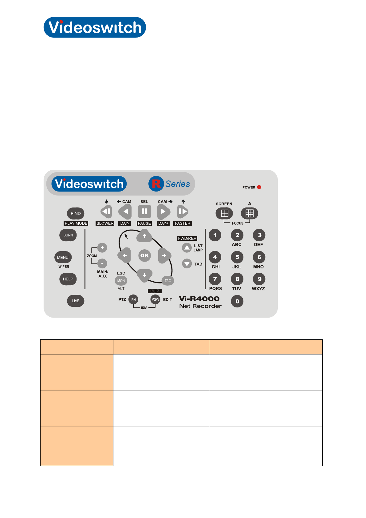
1.2 Control
The R-series Recorders offer various methods of control. A single method or a mixture of methods can
be employed according to personal preference:
• Control by keys in keyboard mode - arrow keys step from field to field in the menus.
• Control by external mouse – a mouse moves pointer smoothly around the screen.
• Control by mouse emulator – the Up/Down/Left/Right, OK and TAG keys perform the
functions of a mouse, moving the pointer smoothly around the screen. Turn mouse emulator
ON or OFF by pressing ESC and TAG together.
1.2.1 Keyboard Control
Key Live or Play Modes Menu/Password Modes
1, 2, 3, 4, 5, 6, 7, 8, 9, 0
Up, Down, Left, Right
OK
0 - 9 Select full screen cameras.
When entering multiple digits,
enter them within ½ second of
each other.
Select cameras 1-4 or 5-8 in
quad mode, or 1-9 or 10-16 in
Multi-screen x9 mode
Start/stop auto sequence Select menu option
Press EDIT key until “123” appear in
edit box. Hold ESC down while using
0-9 for data entry
Move from field to field or move mouse
pointer around screen in mouse
emulator mode. Hold ESC to move
faster.
Press and hold ESC then press OK
key for double click in mouse emulator
mode.
Videoswitch Page 3 Mdr602a.doc

Vi-R4000 Series
FN/PTZ
EDIT
A
FWD/REV/LIST/LAMP
TAB
SCREEN
FIND/PLAY MODE
BURN
MENU
HELP
Press to enter PTZ dome mode
Enter edit mode when a numeric entry
is required in for password or menu.
Also used to delete character when in
edit mode.
Select numeric, alphabetic or symbols
Control LAMP in PTZ mode. Set
Play in Forward or Reverse
Step through tabbed pages
Step through multi-screens.
Enter play mode
Enter Export Mode
Controls wiper in PTZ mode.
Enter MENU mode.
View firmware revision, go to system maintenance menu.
LIVE
MON/ESC/ALT
TAG
SLOWER
DAY-
PAUSE/SELECT
DAY+
FASTER
Return to LIVE mode from any other mode. Shift key for programming
functions.
Shift key for alternate functions. Escape one level in menu.
Right mouse click in mouse emulator mode.
To turn mouse emulator on or off: press and hold ESC key and also press
the TAG key When mouse emulator is ON the arrow pointer appears on
screen. Note that pointer will also be present if a mouse in connected.
Makes replay speed slower
Steps back to prior day. Hold
ESC while pressing to step back
by 10 minutes (programmable)
Switch between play and pause Select menu items or acknowledge
pop-up boxes
Steps forward next day. Hold
ESC while pressing to step back
by 10 minutes (programmable)
Makes replay speed faster
Note: some key functions require you to log on. If so, log on and press the key again.
Videoswitch Page 4 Mdr602a.doc

Vi-R4000 Series
1.2.2 Mouse Control
The DVR can be fully controlled by a mouse and this is recommended especially for ease of system
configuration.
• Move mouse to move pointer around screen
• Right click to bring up menu
• Left click to select items pointed to by the on-screen mouse pointer
Note: The mouse would normally plug into the USB MOUSE port on the rear of the DVR. If you enable
the mouse emulator (i.e. use keys top simulate mouse), the mouse will be disabled.
1.2.3 Mouse Emulator Control
The mouse emulator provides all the control of a mouse but using the front panel keys. The mouse
emulator function may also be used via a remote keyboard,
• Press Left, Right, Up Down keys to move pointer around screen
• Press TAG key to bring up menu when in live mode.
• Press OK key to select items pointed to by the on-screen mouse pointer.
To enable/disable the mouse emulator, press ESC key and at same time, press the TAG key.
1.2.4 External Keyboards
The external keyboard ports support Vi-K1 and Vi-K2 series keyboards and allow remote control of the
DVR. The DVR sends video over CAT5 to the BNC output connectors on each keyboard for
connection to a monitor. When DVRs are cascaded, the keyboard monitor outputs can display images
from any of the DVRs.
Videoswitch Page 5 Mdr602a.doc

Vi-R4000 Series
1.3 Cascading
Cascading is a feature that allows multiple recorders to be linked together.
• Cameras can be called up simply by entering 1-256 on one or more connected keyboards
(e.g. Vi-K1 or Vi-K2).
• All functions including live view, playback and menus from any unit can be accessed via a
single keyboard
• A single VGA or BNC main monitor can be used
• A single BNC spot monitor can be used on each of the three spot outputs
• A single mouse can be used to control all units.
Videoswitch Page 6 Mdr602a.doc

Vi-R4000 Series
2 Installation
Videoswitch Page 7 Mdr602a.doc

Vi-R4000 Series
2.1 Preventive and Cautionary Tips
Before connecting and operating your device, please be advised of the following tips:
• Ensure unit is installed in a well-ventilated, dust-free environment.
• Unit is designed for indoor use only.
• Keep all liquids away from the device.
• Ensure environmental conditions meet factory specifications.
• Ensure unit is properly secured to a rack or shelf. Major shocks or jolts to the unit as a result
of dropping it may cause damage to the sensitive electronics within the unit.
• Use the device in conjunction with an UPS if possible.
• Power down the unit before connecting and disconnecting accessories and peripherals.
• A factory recommended HDD should be used for this device.
• Improper use or replacement of the battery may result in hazard of explosion. Replace with
the same or equivalent type only. Dispose of used batteries according to the instructions
provided by the battery manufacturer.
Videoswitch Page 8 Mdr602a.doc
Vi-R4000 Series
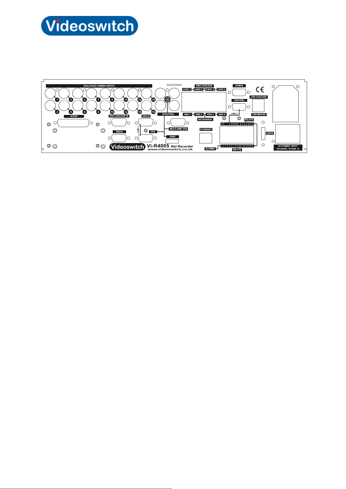
2.2 Rear Panel Connections
2.2.1 Essential Connections
• Connect Cameras to camera inputs 1-8
• Connect VGA monitor to VGA port and/or connect a BNC monitor to MONITOR (CVBS) port.
The two monitors can display different full screen and multi-screens. Note that the VGA
monitor must be connected prior to switching on the DVR as it is auto-detected on boot-up
unless specified as main monitor in the menu.
• Connect mains supply to IEC mains input connector on using IEC cable (included).
2.2.2 Optional Connections
• Connect an HDMI monitor or a DVI monitor (via adaptor cable) to the HDMI port. This will be
the main monitor. Note that the HDMI/DVI monitor must be connected prior to switching on
the DVR as it is auto-detected on boot-up.
• Connect mouse to the rear MOUSE port. Note that while the mouse emulator is enabled, the
mouse is disabled
• Connect Ethernet network to ETHERNET port using CAT5 cable (included)
• Connect Videoswitch remote keyboards to KBD1, KBD2, KBD3, KBD4 ports (Vi-K1 or Vi-K2
range). A BNC video monitor may be connected to the BNC connector on the keyboards.
• Connect dome(s) to outputs 1, 2, 3 and 4 of RS485 Dome port
• Connect alarm device and alarm sensor contacts to ALARMS port
• Connect a USB memory stick to the USB port on the front of the unit (beside the DVD drive)
for exporting video, importing/exporting configuration and for importing firmware updates.
• Connect line level audio input and output equipment. 16 channels of audio are supported. An
audio breakout module is available that provides RCA phono connectors for all channels.
• Cascading – see next section
Videoswitch Page 9 Mdr602a.doc
Vi-R4000 Series
A
A
A
V
V
V
2.2.3 Connecting for Cascade Operation
CASC 3
ALARMS
DOMES
CASC 4
KBD 3
KBD 4
USB CASCADE
CONTROL
USB MOUSE
RELAYS
R-
R+
4
G
3
G
2
T-
1
T+
1
G
G
G
G
eSATA
16
15
14
13
12
11
10
9
8
7
6
5
4
3
2
INPUTS
C POWER INPUT
100-240VAC 50-60HZ 1A
KBD CASCADE
CASC 2
CASC 1
1
3
15
13
9
7
5
3
1
2
CAM 2
CAM 2
CAM 2
6
4
CAM 2
CAM 2
CAM 2
11
CAM 2
CAM 2
CAM 2
12
10
8
CAM 2
CAM 2
GA CASCADE IN
CAM 2
2
4
CAM 2
16
14
CAM 2
MONITORS
VGA IN
KBD 2
KBD 1
KEYBOARDS
ETHERNET
VGA
CABLES
CAT5
USB
CABLES
CABLES
CASC 3
ALARMS
DOMES
CASC 4
KBD 3
KBD 4
USB CASCADE
CONTROL
USB MOUSE
RELAYS
R-
R+
4
G
3
G
2
T-
1
T+
1
G
G
G
G
eSATA
16
15
14
13
12
11
10
9
8
7
6
5
4
3
2
INPUTS
C POWER INPUT
100-240VAC 50-60HZ 1A
KBD CASCADE
CASC 2
CASC 1
1
3
15
13
11
9
7
5
3
1
2
CAM 2
CAM 2
CAM 2
8
6
4
CAM 2
CAM 2
CAM 2
CAM 2
CAM 2
CAM 2
10
CAM 2
GA CASCADE IN
CAM 2
12
CAM 2
2
4
CAM 2
16
14
CAM 2
MONITORS
VGA IN
KBD 2
KBD 1
KEYBOARDS
ETHERNET
1
2
BNC
MONITOR
CASC 3
ALARMS
DOMES
CASC 4
KBD 3
KBD 4
USB CASCADE
CONTROL
USB MOUSE
RELAYS
R-
R+
4
G
3
G
2
T-
1
T+
1
G
G
G
G
eSATA
16
15
14
13
12
11
10
9
8
7
6
5
4
3
2
INPUTS
C POWER INPUT
100-240VAC 50-60HZ 1A
KBD CASCADE
CASC 2
CASC 1
1
3
CAM 2
CAM 2
CAM 2
8
6
4
CAM 2
CAM 2
CAM 2
CAM 2
CAM 2
CAM 2
10
CAM 2
GA CASCADE IN
CAM 2
12
CAM 2
11
9
7
5
3
15
13
2
4
CAM 2
16
14
CAM 2
MONITORS
VGA IN
KBD 2
KBD 1
KEYBOARDS
ETHERNET
MOUSE
VGA
MONITOR
Vi-K
KEYBOARD
Vi-K1 or Vi-K2
KEYBOARD
Vi-K
Vi-K
KEYBOARD
KEYBOARD
BNC
CABLES
BNC
BNC
MONITOR
BNC
MONITOR
MONITOR
Videoswitch Page 10 Mdr602a.doc

Vi-R4000 Series
2.3 Replacing a Hard Drive
If a hard drive needs replacing, the DVR will product an audible warning.
The status of all drives fitted can be checked in this menu:
Menu>HDD>General Status for each drive should be: Normal
If you need to replace a drive:
• Turn off power to the DVR
• Open the door of drive bay using the key provided
• Pull out the drive plate with the drive to be replaced (Drive 1: bottom, Drive 2: top)
• Replace the drive on the metal plate using a small screwdriver
• Push in the drive plate with the new drive back into the bay
• Close the door and lock it
• Power up the DVR and wait until boot has completed. The audible alarm will be sounding.
• Go into this menu: Menu>HDD>General
• Tick the box relating to new drive
• Click on Init to format the drive
• Wait until complete.
Videoswitch Page 11 Mdr602a.doc

Vi-R4000 Series
3 Commissioning
Videoswitch Page 12 Mdr602a.doc

Vi-R4000 Series
3.1 Password Access
If password protection is enabled, a password will need to be selected to gain access to protected
functions such as the menu. When the password box appears, enter the password using one of these
methods:
3.1.1 Keyboard Mode
• If you want to select a different User Name press arrow keys to highlight User Name field,
press OK, press down arrow, press OK again.
• Press arrow keys to select Password field
• Press EDIT key to enter edit mode
• Enter the password using 0-9 keys
• Press OK
• Press arrow keys to select OK on screen
• Press OK
3.1.2 Mouse
• Click on user name if you wish to change it and select another use
• Click on password field, enter password numbers and click on ENTER.
• Click on OK
3.1.3 Mouse Emulator Mode
This is the same as using a mouse, except the up, down, left, right keys are used to move the mouse
pointer and the OK keys act s as a left mouse click.
• Click on user name if you wish to change it and select another use
• Click on password field, enter password numbers and press OK while on ENTER.
• Click on OK
3.1.4 Default Passwords
The Vi-R4000 series DVR is shipped with default users and passwords pre-configured as shown in
this table. Access rights may be changed and other users may be added when logged in as admin. All
default settings may be restored by importing the default configuration from a USB memory stick. If
you change the admin password take care that it is not forgotten.
Username Default Password Access Rights
admin 12345 Access to everything for system configuration
user1 111111 Full local and remote access and configuration
user2 222222 Local and remote viewing, playback and export.
user3 333333 Local viewing, playback and export
user4 444444 Local manual operation of cameras
Videoswitch Page 13 Mdr602a.doc

Vi-R4000 Series
Videoswitch Page 14 Mdr602a.doc

Vi-R4000 Series
3.2 Default Configuration
3.2.1 System Configuration
The DVR is delivered with the system configuration already defaulted.
These settings ensure that it will record and play cameras once correctly connected up. The
configuration settings may be adjusted in the menu to suit the particular installation.
To revert to the default Videoswitch configuration, go to this menu:
Menu >System Maintenance > Import/Export
You can now import the default configuration from the supplied memory stick (using the USB port in
the front panel beside the DVD drive).
The default configuration file is also available on our website:
www.videoswitch.co.uk Firmware Updates
Note: The firmware must match that of the configuration file. If you upgrade the DVR firmware you will
need to export the configuration again if you wish to retain a copy of the settings for future use.
3.2.2 Interface Configuration
The DVR is delivered with the Interface configuration already defaulted.
There are a number of settings relating to the cameras and multi-unit operation that are set by means
of simple 4 digit codes. To prevent accidental operation, the LIVE key must be pressed and held while
these codes are entered. Further protection is provided by a locking facility, using a command to lock
and another command to unlock access to the other functions:
3.2.2.1 Unlock Interface Settings
The interface system is locked on power up. It must be unlocked before any other settings can be
changed. When unlocked, the power LED on the front panel will be OFF.
Press and hold LIVE key, enter 9001, release LIVE key
3.2.2.2 Lock Interface Settings
If you have made changes and wish to lock the Interface settings, apply this command:
Press and hold LIVE key, enter 9000, release LIVE key
Note: if no commands are issued for a minute, the interface will automatically lock. When locked, the
power LED on the front panel will be ON.
3.2.2.3 Display Interface Firmware Revision
The revision of the Interface Controller can be displayed on the power LED by entering this command:
Press and hold LIVE key, enter 9002, release LIVE key
The LED stays on for a few seconds then displays three groups of flashes, encoding a 3-digit revision
number. The sequence is repeated until cancelled.
3.2.2.4 Default all Interface Settings
All Interface setting scan be defaulted by issuing this command:
Press and hold LIVE key, enter 9999, release LIVE key
Videoswitch Page 15 Mdr602a.doc
 Loading...