

Videoswitch Vi-POSCON User Manual

Vi-POSCON Installation Guide
Vi-POSCON
Document Reference
Installation Guide
Date
Pos601a.doc 20/03/2007
Videoswitch
Ocean House, Redfields Industrial Park Fax 01252-851296
Redfields Lane, Church Crookham Email sales@videoswitch.co.uk
Hants GU52 0RD Web www.videoswitch.co.uk
Videoswitch 1 Pos601a.doc
Telephone 01252-851510

Vi-POSCON Installation Guide
Videoswitch 2 Pos601a.doc

Vi-POSCON Installation Guide
Contents
1 CAUTIONS ............................................................................................................................5
2 About this Guide .................................................................................................................... 5
2.1 If you need assistance, call…......................................................................................... 5
3 Introduction............................................................................................................................ 6
4 System Components.............................................................................................................. 7
4.1 Vi-POSCON Front Panel................................................................................................ 9
4.2 Vi-POSCON Rear Panel.................................................................................................9
4.3 The Vi-POSCON Text Overlay..................................................................................... 11
5 Installation............................................................................................................................ 12
5.1 Introduction...................................................................................................................12
5.2 Before You Begin.......................................................................................................... 12
5.3 Pre-Installation Checklist.............................................................................................. 12
5.4 Controller Installation Kits and Tools ............................................................................ 13
5.4.1 Install Kits................................................................................................................ 13
Installation Tools.................................................................................................................. 13
5.5 Installing a Vi-POSCON System................................................................................... 14
5.6 Power-Up Sequence..................................................................................................... 18
6 Configuring the Vi-POSCON System...................................................................................19
7 The Vi-POSCON Service Menu........................................................................................... 20
7.1 Accessing the Service Menu......................................................................................... 20
7.2 Setting the Active Channels.......................................................................................... 21
7.3 Setting the Language.................................................................................................... 21
7.4 Setting the Currency Format......................................................................................... 22
7.5 Setting the Printer Type................................................................................................22
7.6 Displaying the Software Version...................................................................................22
7.7 Setting the Unit Status.................................................................................................. 22
7.8 Setting Synchronize Clock ............................................................................................ 23
7.9 Setting/Activating Alarm Events.................................................................................... 23
7.9.1 Setting the Current Alarm........................................................................................ 23
7.9.2 Setting the Identifier................................................................................................. 24
7.9.3 Setting the Alarm Allocation .................................................................................... 24
7.9.4 Setting the Contact Type......................................................................................... 24
7.9.5 Setting the Alarm Status..........................................................................................25
7.9.6 Setting the Alarm Duration ...................................................................................... 25
7.9.7 Setting the Active Period......................................................................................... 25
7.9.8 Setting the Start Time.............................................................................................. 25
7.9.9 Setting the End Time............................................................................................... 26
7.10 Setting the Channel Attributes...................................................................................... 26
7.10.1 Setting the Current Channel.................................................................................... 26
7.10.2 Setting the Baud Rate ............................................................................................. 26
7.10.3 Setting the Line Filtering..........................................................................................28
7.10.4 Setting the Register Identity .................................................................................... 28
7.10.5 Setting the Text Colour............................................................................................28
7.10.6 Setting the Text Window Border..............................................................................28
7.10.7 Setting the Text Window Position............................................................................29
7.10.8 Setting the Text Window Size.................................................................................. 29
7.11 Setting the Screen Attributes ........................................................................................ 29
7.11.1 Displaying Channel Bar........................................................................................... 29
Displaying Date & Time ....................................................................................................... 30
7.11.2 Setting the Video Type............................................................................................ 30
7.12 Clearing the User Password......................................................................................... 30
7.13 Print System Settings.................................................................................................... 30
7.14 Manager Menu.............................................................................................................. 30
7.15 Event Reports............................................................................................................... 31
8 Troubleshooting................................................................................................................... 32
8.1.1 No Cash Transactions on Monitor........................................................................... 32
8.1.2 No Vi-POSCON Identifying Message on Monitor .................................................... 34
8.1.3 Menus Absent or Distorted on Monitor.................................................................... 36
8.1.4 No Video on Monitor................................................................................................ 36
8.1.5 No Mouse Function ................................................................................................. 36
8.1.6 No Printer Function.................................................................................................. 37
9 Specifications.......................................................................................................................39
9.1 Electrical....................................................................................................................... 39
9.2 Mechanical....................................................................................................................39
9.3 Environmental............................................................................................................... 39
10 Declarations.........................................................................................................................40
Videoswitch 3 Pos601a.doc

Vi-POSCON Installation Guide
Regulatory Compliance................................................................................................. 40
10.1
10.2 Other Declarations........................................................................................................40
Videoswitch 4 Pos601a.doc

Vi-POSCON Installation Guide
1 CAUTIONS
CAUTION: For continued protection against risk of fire, replace only with the same type and rating of
fuse.
PCB Legend Value Type
Fuse F1 1A @ 250V Ceramic "F"
Fuse F2 500mA @ 250V Ceramic "L"
Fuse F3 500mA @ 250V Ceramic "L"
CAUTION: Danger if battery is incorrectly replaced.
Replace only with the same or equivalent type recommended by the manufacturer. Dispose of
batteries according to the manufacturer's instructions.
IMPORTANT!
PLEASE READ CAREFULLY
PURCHASERS WHO INSTALL THIS DEVICE FOR USE BY OTHERS MUST NOT
LEAVE THIS DOCUMENT WITH THE CUSTOMER.
PRECAUTIONS: Check that the operating voltage as indicated on the type plate [label] of the Power
Supply Unit [PSU] is identical with the voltage of your local mains power supply.
LOCATION: For pluggable equipment [which is the PSU], the socket outlet shall be installed near the
equipment, [the PSU], and shall be easily accessible.
Do not expose the Vi-POSCON or the PSU to humidity, rain or excessive heat; they are for use in dry
areas only.
SAFETY: The Mains Plug is considered to be the means of disconnecting primary power. To isolate
the equipment fully, ensure that the Mains Plug is removed.
All Video, Data and Alarm switching signal connections must be to SELV* levels only, in accordance
with EN 6095 and UL 1950 3
INSTALLATION: Both the Vi-POSCON and the PSU are designed to be free standing on a horizontal
surface.
NOTES:
*SELV = Safety Extra Low Voltage.
PSU = Power Supply Unit.
rd
Edition.
A separate copy of this safety card is included with the Vi-POSCON Install Kit and must be left with
the user.
2 About this Guide
This document describes the installation and configuration of the Vi-POSCON System.
2.1 If you need assistance, call…
Videoswitch: 01252-851510
Videoswitch 5 Pos601a.doc

Vi-POSCON Installation Guide
3 Introduction
The Vi-POSCON System is a point-of-sale exception monitoring device that connects to a store's
cash registers and camera surveillance system.
The Vi-POSCON System monitors EPoS (Electronic Point-of-Sale or cash register) terminal activity
and documents suspicious sales transactions. It does this by monitoring the register data for up to 10
sales transactions that the operator has designated as exception events. It also monitors up to four
external switch events (such as door switch or panic button).
When an exception event occurs, Vi-POSCON documents the event by:
Switching the DVR from time-lapse to real-time recording to record the register scene.
Displaying the register scene on a video monitor in a back room or office.
Highlighting the exception on the register receipt that overlays the video scene.
Generating a one-line printout that summarizes the exception event (if the Audit Trail option is
enabled).
Storing exception event information for the system reports.
By sounding an alarm tone.
Changes the relevant front panel Data LED from flashing green to steady red for the duration of the
event.
By lighting the red EVENT LED when the first event is logged. (The LED is not cleared until the event
is reviewed.)
After the system documents an exception, it:
Returns to routine surveillance, monitoring the register data according the surveillance parameters
you defined.
Switches the DVR from real-time to time-lapse recording.
Changes the relevant front panel Data LED from steady red to flashing green.
The Vi-POSCON System stores exception event data in its memory for generating its reports. The
Detailed Event Report provides complete details of the exception events. The Frequency Event
Report totals the number of exception events occurring per hour accumulatively over a number of
days. The Daily Report totals the number of exception events occurring per hour for a single day, for
up to 7 days. You can display and print the reports.
Videoswitch 6 Pos601a.doc
Vi-POSCON Installation Guide
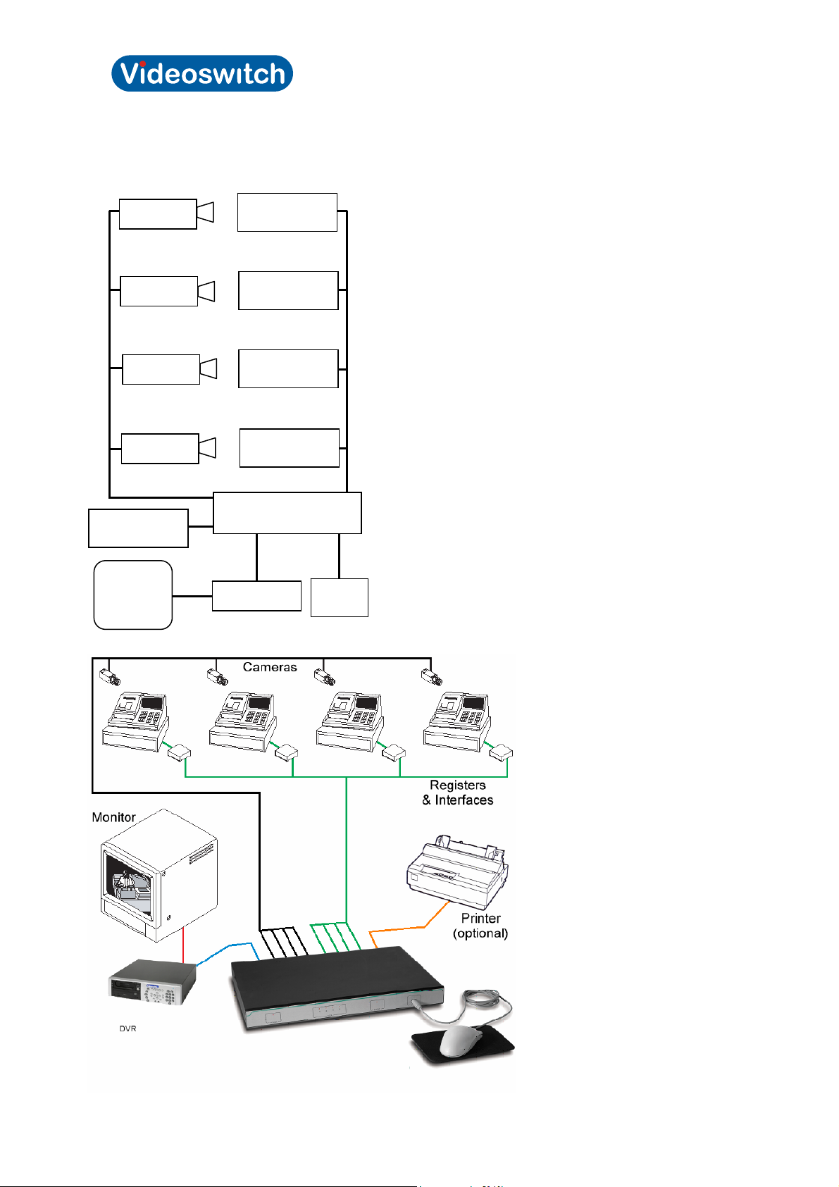
4 System Components
The following illustration shows the components of a typical Vi-POSCON System for a single register
installation. Vi-POSCON can monitor up to four cash registers with a single DVR and video monitor.
Depending upon the specific needs of each installation, the system setup will vary from site to site.
The Vi-POSCON components required for a single cash register installation are described b elow. The
printer is optional, but is typically included.
Camera Provides video of the register scene or, if using a programmable
dome, other locations in the store.
Cash register The EPoS or electronic cash register system used to execute sales
related transactions. In this guide, the term register is used
interchangeably with EPoS.
Monitor Displays the live register scene, an overlay of the register receipt on
the register scene, and Vi-POSCON menus.
Mouse A pointing device used to control and program the Vi-POSCON
System.
Printer
(optional)
Vi-POSCON Controller Controls the Vi-POSCON System for up to four registers and
Printer Port Interface (PPI) Connects a register to the Vi-POSCON controller; it converts the
DVR Records (in time-lapse mode) the register scene. When an exception
Prints a record of exception events as they occur, and prints
summary event reports.
cameras, including the switching of a time-lapse DVR.
It can also control the monitoring of up to four external switch events
(alarms), such as door switch or panic button.
register data into Vi-POSCON-understandable data.
occurs, the DVR records (in real-time mode) the register scene along
with an overlay of the register receipt.
Videoswitch 7 Pos601a.doc
Vi-POSCON Installation Guide
The following illustration shows the maximum Vi-POSCON System configuration with one DVR and
monitor. You can connect up to four registers, cameras, DVRs, and monitors to the Vi-POSCON
controller. A Printer Interface is required for each register you want to monitor.
Camera 1
EPoS & Printer
Interface
Printer
(optional)
Video
Monitor
Camera 2
Camera 3
Camera 4
EPoS & Printer
Interface
EPoS & Printer
Interface
EPoS & Printer
Interface
Vi-POSCON
Controller
VCR or DVR
Mouse
Videoswitch 8 Pos601a.doc
Vi-POSCON Installation Guide
4.1 Vi-POSCON Front Panel
The following is a escription of the Vi-POSCON front panel indicators and connector.
POWER – This red LED, when lit, indicates that the unit is powered on.
DATA – These four tri-colour LEDs are linked to the four data input ports on the rear panel. These
LEDs flash green as data is received at the associated interface input; they turn steady red as and
when an event occurs, reverting to flashing green once the period of time defined for the event has
lapsed. If no data is being received at a particular port then the associated LED is not lit.
EVENT – This red LED lights when the first event is logged into Vi-POSCON memory and remains lit
until the user has reviewed that event and all other subsequent logged events.
On system power-up, the DATA and EVENT LEDs momentarily light red.
MOUSE – This is a mini-DIN socket for connecting a PS/2 mouse to the Vi-POSCON System. A tick-
mark indicates the location of the connector's key.
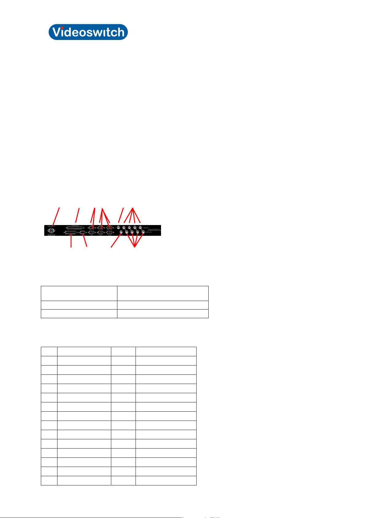
4.2 Vi-POSCON Rear Panel
The following is an illustration and description of the Vi-POSCON rear panel connectors.
[A] [B] [E] [F] [G] [I]
[C] [D] [H] [J]
[A] Power Input – a DIN connector for the power supply unit (PSU). The following table identifies the
power supplies to be used with the Vi-POSCON Systems.
For Vi-POSCON Systems
in:
North America 590001
Europe 590002
Use Power Supply Part
Number:
[B] Alarms I/O & VCR/DVR – a 37-pin D-type female connector for alarm inputs, relay outputs, and
DVR.
Pin Assignment Pin Assignment
1 Relay 1 NO* 20 Relay 1 COM
2 Relay 1 NC* 21 unassigned
3 Relay 2 NO 22 Relay 2 COM
4 Relay 2 NC 23 unassigned
5 Relay 3 NO 24 Relay 3 COM
6 Relay 3 NC 25 unassigned
7 Relay 4 NO 26 Relay 4 COM
8 Relay 4 NC 27 unassigned
9 Relay 5 NO 28 Relay 5 COM
10 Relay 5 NC 29 unassigned
11 unassigned 30 unassigned
12 unassigned 31 unassigned
13 unassigned 32 unassigned
14 unassigned 33 unassigned
Videoswitch 9 Pos601a.doc
Vi-POSCON Installation Guide
15 unassigned 34 Alarm GND
16 Alarm Input 4 35 Alarm GND
17 Alarm Input 3 36 Alarm GND
18 Alarm Input 2 37 Alarm GND
19 Alarm Input 1
* NO = Normally Open; NC = Normally Closed
Relay 1 is associated with Channel 1, Relay 2 with Channel 2, Relay 3 with Channel 3, and Relay 4
with Channel 4.
Relay 5 is associated with the Main Monitor output and if Vi-POSCON is configured as a standalone
system, this relay should be connected to the Alarm Input of the time-lapse DVR.
Pin Assignment Connect to DVR
9 Relay 5 NO Alarm SET
10 Relay 5 NC Alarm RESET
28 Relay 5 COM Alarm GROUND
[C] Printer – a 25-pin D-type female connector for connecting the Vi-POSCON printer.
[D] 485 – a 9-pin D-type RS-232/RS485 female connector for future use (to allow the connection of
multiple Vi-POSCON controllers).
[E] 232A and 232B – two 9-pin D-type RS-232 male connectors.
232A is used to output the Synchronizing Clock data to other equipment.
232B is for future use.
The RS-232 output is fixed
at 9600, N, 8, 1.
[F] Data1 through Data4 – four 9-pin D-type RS-232/RS-485 male connectors for input from the
Printer Port Interfaces. (The Printer Port Interfaces can output data in either RS-232 or RS-485.)
Wire
Colour
RS-232
Data In
Pin
Wire
Colour
RS-485
Data In
Pin
RED 2 – RXD 4 – RX+
BLACK 5 – GND 5 – GND
9 – RX-
Note: Jumpers on the Vi-POSCON main PCB must be set to allow RS-232 or RS-485 data input. RS232 is the default setting for all four interface data input channels. Interface data input channels may
be set in any combination of RS-232 or RS-485 input.
RS-232/RS-485 Interface Data Input
Data
Jumper RS-232 Data Input RS-485 Data Input
Input
Channel
1 P12
2 P11
For RS-232, set
jumper towards rear
of unit (default).
For RS-485, set jumper
towards front of unit.
3 P10
4 P9
[G] AUX – a BNC connector for future use.
[H] Main Mon. – a BNC connector for the main monitor when Vi-POSCON is configured as a
standalone system (more than one camera/register input with output to a single DVR/monitor).
[I] Video Input (1 through 4) – four BNC connectors for camera input.
Videoswitch 10 Pos601a.doc
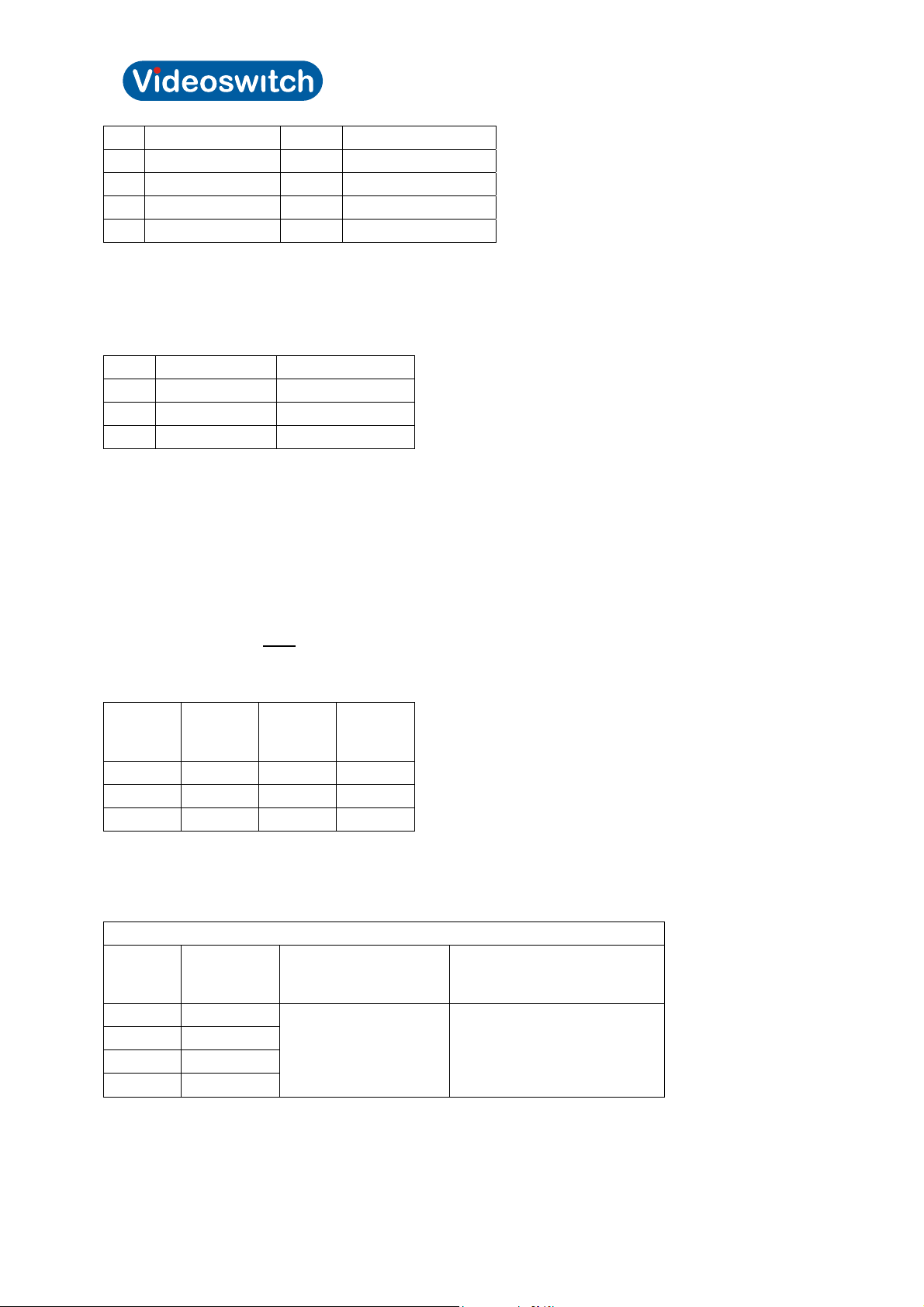
Vi-POSCON Installation Guide
Video Input Jumper Notes
1 JP5
2 JP4
3 JP3
4 JP2
AUX JP1
For future use
[J] Video Output (1 through 4) – four BNC connectors for video output. The video output signals
include the text overlay from the EPoS.
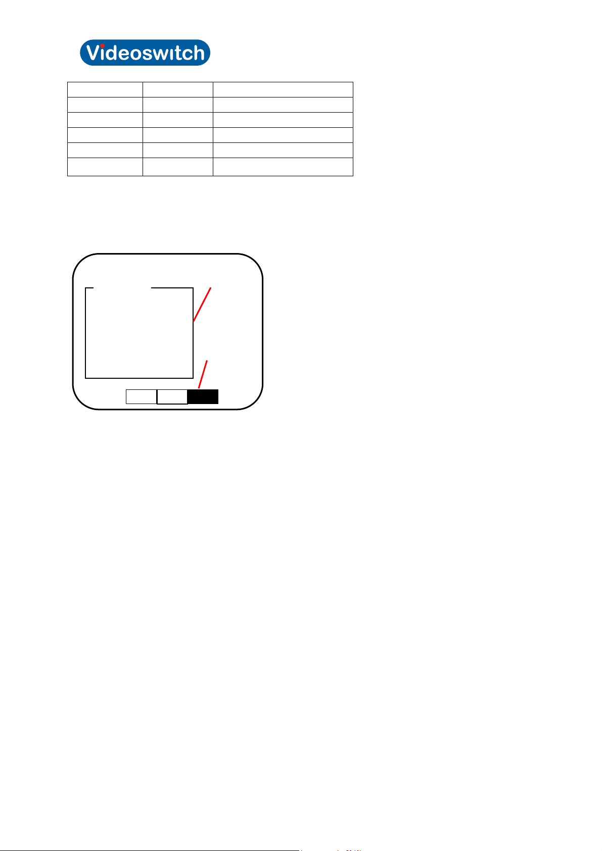
4.3 The Vi-POSCON Text Overlay
The monitor text overlay of the Vi-POSCON System is similar to the following illustration. The
surveillance scene is omitted for clarity.
HH:MM:SS Store Identifier DD/MM/YY
Register 3
Orange Juice 0.89
Whole Milk 1.23
Skimmed Milk 1.18
Baked Beans 0.26
4 Items 3.56
Tax 0.21
Total 3.77
Cash 5.00
Change 1.23
Transaction
window
Channel Bar
2
The 3-part text line at the top of the monitor screen displays:
The time in either 12-hour or 24-hour format,
Up to 20 characters for the store's identifier, and
The date in DD/MM/YY, MM/DD/YY, or YY/MM/DD format. (Note: the system replaces the date
separator "/" with "." for the German, Polish, Finnish, Hungarian, Czechoslovakian and Russian
languages, and "-" for the Portuguese and Danish languages.)
The Transaction window displays all register transactions as they occur. The window displays a
maximum of 40 characters per line (38 characters if an outline border is selected). A 12-character
register name box is displayed at the top of the Transaction window.
In the Surveillance Mode, the Channel Bar at the bottom of the screen displays numbered boxes to
indicate the activated video input channels. The example in the above figure shows three activated
channels with Channel 3 being monitored (highlighted). When an event occurs, the system switches
to the channel reporting the event, and its box highlights.
When an Alarm (External) event occurs, the Store Identifier is replaced by a highlighted, flashing
ALARM # (where # = the number of the Alarm) or the Alarm Identifier text (if entered, for example:
DOOR). At the end of the event duration, the Store Identifier is restored.
Videoswitch 11 Pos601a.doc

Vi-POSCON Installation Guide
5 Installation
5.1 Introduction
This section describes how to install and configure a single controller Vi-POSCON System.
5.2 Before You Begin
Verify that all the equipment has arrived.
Verify that the unit shipped is the right configuration for the store.
Be organized. Unpack components in the back room. At the installation area, lay out parts in the order
you will need them. Do not clutter traffic areas or cause a safety hazard.
5.3 Pre-Installation Checklist
5.3.1.1.1 Salesperson's Responsibilities
Key contacts identified.
Special installation dated noted (verify with Customer Engineer).
Electronic cash register types and printers are identified.
5.3.1.1.2 Customer's Responsibilities
Unswitched, 120Vac or 240Vac, 15A power provided at designated locations to supply the printer
interface(s) and operator station equipment-controller(s), monitor, printer, DVR, and quad splitter, if
installed.
A person with technical knowledge of the electronic cash register system scheduled to sup port the ViPOSCON installation.
5.3.1.1.3 Customer Engineer Responsibilities
Register types noted.
With agreement of the customer, location of the Vi-POSCON station and other components
determined; see Placement below.
Cabling distances between registers and all Vi-POSCON components. A printer interface and data
cable is required for each cash register to be monitored.
5.3.1.1.4 Placement
Vi-POSCON controller location determined, within 2.5m (8') of camera system card rack (if used ) for
cable connections.
Printer interface location at registers determined, within 0.9m (3') of AC receptacle.
Four-conductor data cable run from each printer interface to the Vi-POSCON controller.
5.3.1.1.5 AC Power
Three receptacles of unswitched 120Vac or 240Vac, 15A power for the monitor, printer, and DVR. A
fourth receptacle is required if a quad splitter is used.
One receptacle of unswitched 120Vac or 240Vac, 15A power for each Vi-POSCON controller.
One receptacle of unswitched 120Vac or 240Vac, 15A power for each printer interface.
Less than 0.5Vac between neutral and ground of all AC receptacles.
Videoswitch 12 Pos601a.doc
Vi-POSCON Installation Guide
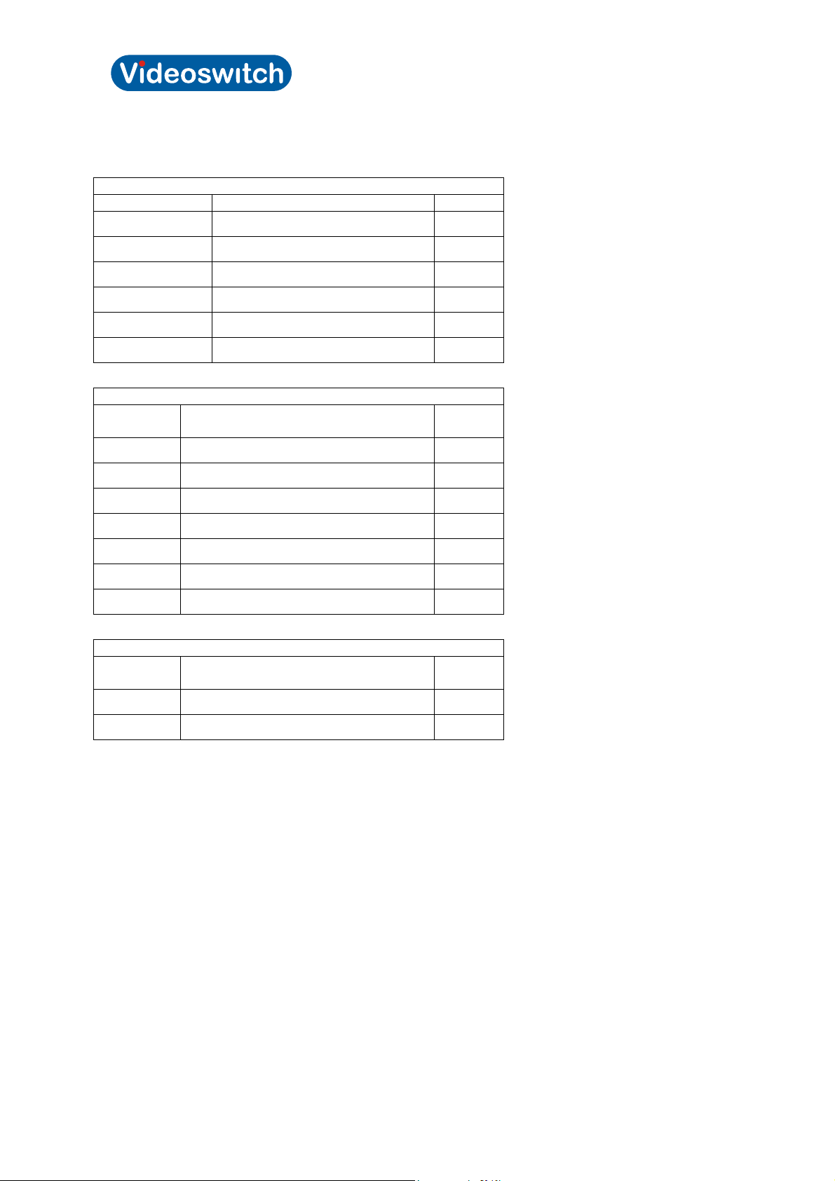
5.4 Controller Installation Kits and Tools
5.4.1 Install Kits
Vi-POSCON Install Kit (US) 540012
Part Number Description Qty
590001 USA PSU 1
520079 37-way D Plug (Solder Bucket) 1
520078 37-way D Cover 1
520075 9-way D Socket (Crimp) 4
520030 9-way D Cover 4
520076 Crimp Pin 12
Vi-POSCON Install Kit (EU) 540013
Part
Number
590002 EUR PSU 1
Description Qty
500261 UK Power Cord 1
500262 EUR Power Cord 1
520079 37-way D Plug (Solder Bucket) 1
520078 37-way D Cover 1
520029 9-way D Socket (Solder Bucket) 4
520030 9-way D Cover 4
Accessories
Part
Description Qty
Number
590003 Mouse 1
590004 Mouse Mat 1
NOTE: Any replacement or alternative mouse used with the Vi-POSCON system must be UL
approved.
Installation Tools
You will need the following tools to properly install Vi-POSCON:
Crimp tool, D-sub (for Crimp Pin Part #: 520076)
Extractor, D-sub (for Crimp Pin Part #: 520076)
Multimeter or equivalent
Wire stripper/crimper
Soldering iron
Measuring tape
Drill, bits, and screws as needed for mounting (typically to wood)
Drill, bits, and saw as needed for cable routing (typically through wood)
Videoswitch 13 Pos601a.doc
 Loading...