

Videoswitch Vi-D5000 User Manual
Vi-D5000 Series CMOR IR Dome
User Manual
Products covered by this manual
Vi-D5030, Vi-D5036
Document Reference Vd601a.doc
Date 10-Feb-14
Videoswitch Telephone 01252-851510
Ocean House, Redfields Industrial Park Fax 01252-851296
Redfields Lane, Church Crookham Email sales@videoswitch.co.uk
Hants GU52 0RD Web www.videoswitch.co.uk


PRECAUTIONS
1. Persons without technical qualifications should not attempt to operate this dome device before reading this
manual thoroughly.
2. Remove any power to the dome before attempting any operations or adjustments inside the dome cover to
avoid potential damage to the mechanism.
3. Inside the dome cover there are precision optical and electrical devices. Heavy pressure, shock and other
sudden adjustments or operations should be avoided. Otherwise, you may cause irreparable damage to
the product.
4. Please DO NOT remove or disassemble any internal parts of the video camera to avoid normal operation
and possibly void the warranty. There are no serviceable parts inside the camera.
5. All electrical connections to the dome should be made in strict accordance with the attached labels and
wiring instructions in this manual. Failure to do so may damage the dome beyond repair and void the
warranty.
6. For outdoor installation especially in high places or poles, it is highly recommended that the proper
lightning arrestors and surge suppressors are installed before the dome is entered into service.
7. Please do not use the product under circumstances where the limits exceed the maximum specified
temperature, humidity or power supply specifications.
IMPORTANT SAFEGUARDS
1. Read these instructions before attempting installation or operation of dome device.
2. Keep these instructions for future reference.
3. Heed all warnings and adhere to electrical specifications. Follow all instructions.
4. Clean only with non abrasive dry cotton cloth, lint free and approved acrylic cleaners.
5. Should the lens of the camera become dirty, use special lens cleaning cloth and solution to properly clean
it.
6. Do not block any ventilation openings. Install in accordance with manufacturer’s instructions.
7. Use only attachments or accessories specified by the manufacturer.
8. Verify that the surface you are planning to use for attaching the dome can adequately support the weight of
the device and mounting hardware.
9. Protect this devices against lighting storms with proper power supplies.
10. Refer all servicing to qualified service personnel. Servicing is required when the device has been damaged
in any way, when liquid traces are present, or the presence of loose objects is evident or if the device does
not function properly, or has received sever impact or has been dropped accidentally.
11. Indoor dome is for indoor use only and not suitable for outdoor or high humidity locations. Do not use this
product under circumstances exceeding specified temperature and humidity ratings.
12. Avoid pointing the camera directly to the sun or other extremely bright objects for prolonged period of
time avoiding the risk of permanent damages to the imaging sensor.
13. The attached instructions are for use by qualified personnel only. To reduce the risks of electric shock, do
not perform any servicing other than contained in the operating instructions unless you are qualified to do
so.
14. During usage, user should abide by all electrical safety standards and adhere to electrical specifications for
the operation of the dome. The control cable for RS485 communications as well as the video signal cables
should be isolated from high voltage equipment and high voltage cables.
15. Use supplied power supply only.

INDEX
1 Overview.................................................................................................................................................................... 1
1.1 Model Specific.................................................................................................................................................. 1
1.2 Specification..................................................................................................................................................... 1
1.3 Performance Features ..................................................................................................................................... 2
1.4 Function Description ........................................................................................................................................3
2 Installation ................................................................................................................................................................. 5
2.1 Installation Sequence....................................................................................................................................... 5
2.2 Connection Details ........................................................................................................................................... 6
2.3 DIP Switch Settings.......................................................................................................................................... 6
2.3.1 Preparation.................................................................................................................................................. 7
2.3.2 Address Settings ......................................................................................................................................... 7
2.3.3 Baud Rate Settings .....................................................................................................................................7
2.3.4 RS485 Bus Termination ..............................................................................................................................8
2.4 Bracket Dimensions ......................................................................................................................................... 9
2.4.1 Vi-B16 Wall mounting Bracket..................................................................................................................... 9
2.4.2 Vi-B13 Corner Adaptor Bracket ................................................................................................................... 9
2.4.3 Vi-B14 Pole Adaptor Bracket..................................................................................................................... 10
2.4.4 Vi-B12 Swan-Neck Bracket ....................................................................................................................... 10
2.4.5 Vi-B15 Pendant (ceiling) Bracket............................................................................................................... 11
2.5 Installation of Brackets ................................................................................................................................... 11
2.5.1 Vi-B16 Wall Mounted................................................................................................................................. 11
2.5.2 Vi-B13 Corner Mount Adaptor ................................................................................................................... 12
2.5.3 Vi-B14 Pole Mount Adaptor....................................................................................................................... 14
2.5.4 Vi-B15 Pendant (ceiling) Bracket............................................................................................................... 15
3 Operation................................................................................................................................................................. 18
3.1 Power Up Action ............................................................................................................................................18
3.2 Basic Function................................................................................................................................................ 19
3.3 Special Function Presets ............................................................................................................................... 20
3.4 On-Screen Display (OSD).............................................................................................................................. 20
3.4.1 Normal Mode............................................................................................................................................. 20
3.4.2 Menu Mode ...............................................................................................................................................21
4 OSD Menu ............................................................................................................................................................... 22
4.1 Menu Structure............................................................................................................................................... 22
4.2 System ........................................................................................................................................................... 23
4.2.1 Comm Set ................................................................................................................................................. 23
4.2.2 Password Set ............................................................................................................................................ 23
4.3 Dome .............................................................................................................................................................23
4.3.1 Preset........................................................................................................................................................ 23
4.3.2 Scan .......................................................................................................................................................... 23
4.3.3 Guard Tour ................................................................................................................................................ 24
4.3.4 Pattern....................................................................................................................................................... 24
4.3.5 Privacy Zone .............................................................................................................................................24

4.3.6 Other ......................................................................................................................................................... 25
4.3.7 Alarm......................................................................................................................................................... 25
4.3.8 Wiper......................................................................................................................................................... 25
4.3.9 Track (Some models only)......................................................................................................................... 25
4.4 Camera .......................................................................................................................................................... 26
4.4.1 Camera Advanced (some models only) .................................................................................................... 26
4.4.2 Camera AE (some models only)................................................................................................................ 26
4.5 IR Set ............................................................................................................................................................. 26
4.6 Display ........................................................................................................................................................... 27
4.7 Time ............................................................................................................................................................... 27
4.8 Language ....................................................................................................................................................... 28
4.9 Reset.............................................................................................................................................................. 28
5 Appendices .............................................................................................................................................................. 29
5.1 Anti-lightning, Anti-surge ................................................................................................................................ 29
5.2 Clean Camera Window .................................................................................................................................. 30
5.3 RS485 Bus..................................................................................................................................................... 30
5.3.1 Basic Feature of RS485bus....................................................................................................................... 30
5.3.2 Mode of Connection and Terminal Resistance.......................................................................................... 30
5.4 Address Code Mapping Table........................................................................................................................ 31
5.4.1 Dome address code mapping table for PELCO_D .................................................................................... 31
5.4.2 Dome address code mapping table for PELCO_P .................................................................................... 32
5.5 32
6 Problem solving ....................................................................................................................................................... 33
Vi-D5000 IR Dome
1 Overview
1.1 Model Specific
Vi-D5030 Vi-D5036
Analogue Zoom x30 x36
Digital Zoom x12 x12
TVL 800 540
BLC No Yes
WDR No Yes
Wiper Yes Yes
IR Range up to 150m 150m
Privacy No Yes
Tracking No No
1.2 Specification
Horizontal Rotation Speed 0.02°-280°/s
Tilt Rotation Speed 0.02°-160°/s
Horizontal Rotation Range 360°
Tilt Rotation Range 93°
Auto Flip Horizontal 180°, Vertical 90°
Auto control IR LED PWM
A-B Scan User programmable
A-B Scan Speed 1-9 speed setting available
360° Scan Speed 1-9 speed setting available
Dwell Preset 5-60s interval
Preset Points 220
Go to Preset Speed 200°/s
Guard Tours 4 groups
Guard Points Max.16 points, dwell time user selectable
Pattern Scan 4 patterns
Pattern Scan Record max.15 minutes, max.512 commands
Home Pos Time 1-60mins available
PWR on Action
Communication Protocol
Communication RS485 Bus
Baud Rate 1200/2400/4800/9600bps
Time Scheduling function 8 tasks
Operating Temperature Outdoor: -40°~ +60°
Operating humidity ≤95% Non Condensing
Heater & Blower Auto temperature control
Power AC/DC15-28V ≤3A
Lightning protection transient voltage 3000V
LED Angle of Illumination Ø20=8,Ø16=5
Memory as power off/Pattern/360° scan/A-B
scan/Preset cruise/Preset 1-8/No action
Pelco-D, Pelco-P (BBV up-the-coax via PSU option
module)
Videoswitch Page 1 VD601A.DOC

Vi-D5000 IR Dome
1.3 Performance Features
• PWM function. Intelligent IR illumination & power consumption is variable,dependant the zoom factor.
• 3D allocation. That screen coordinate location and zoom local are performed at the same time can be
available.
• Privacy masking. 24 privacy masking areas can be random set (module support).
• Supported Protocols. Pelco-D and Pelco-P at 1200, 2400, 4800 or 9600 baud
• 4 path patterns. Each path can record 512 different points or 15minutes max duration.
• Manual control speed. The lowest 0.02º/s rate allows very smooth control
• 4 guard groups. All 16 preset points of each group can edit independently dwell position and time.
• Built-in high density RTC clock supports time management function.
• Park action. If dome not operated within a set time, it will automatically run preset guard group, pattern
group, pan scan etc.
• Memory of operation before power off.
• Built-in fan and heater control theinternal temperature automatically.
• Heater opens below 0°C and fan opens above 40°C.
• Multiple languages for OSD menu, English, Spanish, Chinese etc.
• Illumination on low ambient light is adjustable.
• Accurate step motor control makes it stable running, precise location and sensitive reaction.
• Completed metal body construction, waterproof IP66.
• Built-in 3000V anti-lighting and anti-surge protection equipment.
• 8-input Alarm Option
• Up-the-coax BBV protocol option
Videoswitch Page 2 VD601A.DOC

Vi-D5000 IR Dome
1.4 Function Description
Alarm Module (Option)
Dome camera supports 8 switch alarm inputs, 1 relay output. When the dome camera has detected the alarm
closed signal, it will call up the corresponding preset 1 to 8.
Tracking (Option)
It targets and tracks automatically the moving object in the screen according to the parameter specified by
user. The tracking scene, size of object, tracking sensitivity and return time when the object is lost can be
settable.
Auto-adaptive to Protocol and Module
The dome can auto-sense the protocol and most comms settings can be made without need to change any
DIP switches.
3D Allocation
With this function users can move the image of some area to the centre of screen according to specified level
and vertical coordinates and auto control to zoom according to zoom parameter set. Screen coordinate
location and zoom local can be available via the software support.
Privacy Masking (Option)
In the monitoring scope, areas that users can’t or aren’t willing to make show in the screen of the monitor can
be set as privacy protected area (area masking), such as area where customers enter the password in
monitoring system of bank or some doorway.
Trace Memory (Pattern Scan)
The traces of camera’s any running action in every directions of PTZ can be saved, which is called pattern
scan. In pattern scan the camera turning to up, down, left and right and zooming in or out can be saved. This
function remembers and imitates a process of operator’s operation.
This dome camera has 4 path patterns. Each path can record 512 different instructions or the longest 15mins’
path operation. Opening any one of the paths can remember automatically the present running trace and scan
cyclically according to the recorded trace.
Auto Flip
In the manual tracking mode, when a target goes directly beneath the dome, the dome will automatically rotate
180 degree in horizontal direction to maintain continuity of tracking. When the dome flips, the camera starts
moving upward as long as you hold the joystick in the down position.
Focus
The auto focus enables the camera to focus automatically to maintain clear image. User can use manual focus
too in special conditions.
Under the following conditions camera will not be able to reliably auto focus on the camera target:
• Target is not in the centre of the screen
• Attempting to view images that are far and near at the same time
• Target is strongly lighted object, such as neon lamp, etc.
• Targets are behind the glass covered with water droplets or dust
Videoswitch Page 3 VD601A.DOC

Vi-D5000 IR Dome
• Targets are moving quickly
• Featureless large area targets, such as wall;
• Targets are too dark or faint.
Back Light Compensation (some models only)
If a bright backlight is present, the target in the picture may appear dark or as a silhouette. BLC enhance the
target in the centre of the picture, the dome uses the centre of the pictures to adjust the iris. If there is a bright
light source outside this area, it will wash out to white, the camera will adjust the iris so that the target in the
sensitive area will properly exposed.
Iris Control (some models only)
Factory default is automatic camera aperture, in mode of which camera senses changes in ambient light
through moving and adjust automatically lens aperture to make the brightness of output image stable.
Ratio Speed
Intelligent pan and tilt speed is variable depend on the zoom factor. When zooming in, the speed will become
slower and when zooming out, the speed will become faster.
Pan Scan
Dome 360°clockwise continuously scans the display scene at set speed in horizontal direction under the
condition that pitch angle remains the same. In the scanning status, operator can move the joystick to exit from
scanning.
Preset
After the dome camera keeps arbitrary PTZ location, it will automatically move to the defined position when
preset is called.
Guard Tour Scan
Dome patrol scans according to certain edited preset order.
A-B Scan
Dome circularly scan close-up real-time scene according to A-B points at setting speed in both horizontal and
vertical directions.
Power Off Memory
This feature allows the dome to resume its previous preset or status after power is restored. By default setting,
the dome support power up memory, which improves the reliability and avoids repeated settings of the
parameter.
Park Action
If users don’t operate the dome in set time, it will automatically run preset specific mode (pan scan, A-B scan,
park action, cruise, preserve action etc).
Multi-language OSD Menu
The available language used on screen menu can be English, etc. User can set the function or parameter, or
check the related information through the OSD.
Videoswitch Page 4 VD601A.DOC

Vi-D5000 IR Dome
2 Installation
2.1 Installation Sequence
The following sequence is suggested when installing the dome:
• Remove hinged cap from the top of the dome, carefully unplugging internal connector. Put dome in a
safe place until needed.
• Feed umbilical cable through wall, or trunking and then through the chosen bracket
• Connect a grounding wire to the green wire of the dome cable (coming from the hinged dome cap).
Connect the grounding wire to an earth stake or to the bracket if this is already earthed. This is to
protect the dome from lightning.
• Plug the dome cable (coming from the hinged dome cap) into the umbilical cable. Connect both the
power/control pluggable terminals and the video BNC
• Attach the hinged dome cap to bracket, making sure the hinge is at the front or to one side. Tighten the
three equi-spaced screws to make the dome cap secure
• Stow the wires and connections within the bracket and attach the bracket to wall/pole/ceiling as
required
• Carefully handling the dome, connect the dome safety cable to the bracket
• Hook dome onto the hinged dome cap
• Plug internal connector into dome top
• Hinge dome up into its normal position and tighten the screws that fix hinged cap to dome. Make sure
rubber gasket is properly seated to make a waterproof seal.
• Connect PSU end of umbilical into the PSU (make sure it is turned off)
• Connect controller/display to PSU. Both video and RS485 cables should be connected unless the PSU
has an up-the-coax module fitted in which case only the video cable is required.
• Power up and test
• Make sure all external wiring is made waterproof, using silicone rubber sealant as required
Videoswitch Page 5 VD601A.DOC

Vi-D5000 IR Dome
2.2 Connection Details
Note
A 5m umbilical cable is included
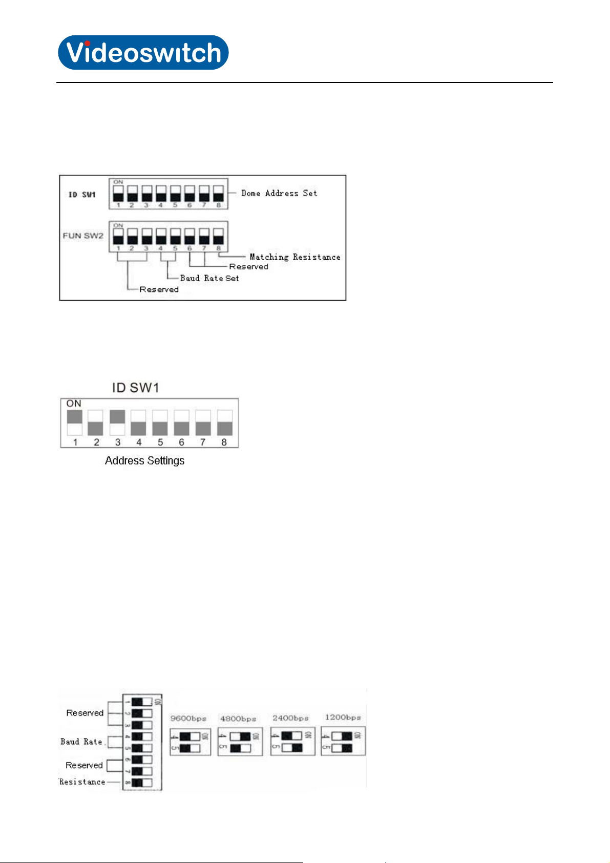
2.3 DIP Switch Settings
The dome has DIP switches for setting protocol, baud rate, termination and address. All these settings except
termination can be made from within the menu, so typically there is no need to access these switches. If
required, the DIP switches are accessible by removing a panel on the side of the dome just above the camera
lens. Ensure the waterproof seal is restored when replacing the panel.
Videoswitch Page 6 VD601A.DOC
Vi-D5000 IR Dome
2.3.1 Preparation
Before installation, make sure that the protocol, baud rate and address code used by the product is fully
consistent with the control system. The individual DIP switch functions can be seen below:
2.3.2 Address Settings
DIP switch SW1 is the address settings of camera. It is a 8-bit switch. Each switch corresponds with 0 or 1 in
the Binary code. OFF status means 0 while ON status means 1.
For example, turn on the 1st and 3rd (allocated to ON position) and get the binary code 00000101, so the
correspondence address is 5.
For details of settings please refer to the back “Address Code Mapping Table”(Section
If you wish to change the address in the menu rather than using the DIP switches, you will need to
communicate with the dome using its default address to start with.
5.4).
2.3.3 Baud Rate Settings
The 4th and 5th DIP Switches set the Baud rate. Factory-default setting is 2400bps. Baud rate options are
1200, 2400, 4800, 9600.
If you wish to change the baud rate in the menu rather than using the DIP switches, you will need to
communicate with the dome using its default baud rate to start with.
Videoswitch Page 7 VD601A.DOC
 Loading...