


Viconics Wireless Controller Driver Guide
Wireless Controller Driver Guide
Used With VWG-APP-1000 Wireless Card
For Tridium® JACE 2, 6 & 7® Series Product
(028-6018 R4 Issue Date: June 5h, 2012)
Product Overview
The VWG-APP-1000 wireless communication card and related “WirelessTstat” driver jar file have been specifically designed to be used by Niagara AX® powered JACE controllers.
When utilized in conjunction with the Viconics wireless controllers they offer the integrator simple integration to the Niagara AX® Workbench environment.
The application is targeted at retrofit applications where the addition of communicating field bus wiring within the building space is prohibitive. The JACE communication card and associated Wireless Communicating Controllers encourages the use of existing wiring utilized by existing electronic controller type controls.
Additional documentation is available on www.viconics.com
1
Compatibility & History Revision Table
Release 1, May 2009
|
|
|
|
Revision |
|
|
Associated |
|
|
|
|
|
|
|
|
|
|
|
|
|
|
||||
|
|
|
|
|
|
|
|
|
||||
|
Associated Jar Files |
|
|
|
|
Displayed Driver |
|
|
Compatible Devices |
|
||
|
|
|
Level |
|
|
|
|
|
||||
|
|
|
|
|
|
Name |
|
|
|
|
||
|
|
|
|
|
|
|
|
|
|
|
|
|
|
|
|
3.1.30 |
|
|
|
|
|
|
|
||
|
|
|
|
|
Main |
|
|
|
|
VT7200 Zone wireless controllers |
||
|
WirelessStat.jar |
|
|
2.1 |
|
|
WirelessStatNetwork |
|
|
VT7300 FCU wireless controllers |
||
|
|
|
|
|
2.1.1 |
|
|
|
|
|
VT7600(A,B) Staging wireless controllers |
|
|
|
|
|
|
2.1.2 |
|
|
|
|
|
|
|
Compatible VT7200 Zone wireless controllers are identified with wireless module 051-0021 Rx
Compatible VT7300 FCU wireless controllers are identified with wireless module 051-0021 Rx
Compatible VT7600 Staging wireless controllers are identified with wireless module
051-0022 Rx
Release 2, June 2010
|
|
|
|
Revision |
|
|
Associated |
|
|
|
|
|
|
|
|
|
|
|
|
|
|
||||
|
Associated Jar Files |
|
|
|
|
Displayed Driver |
|
|
Compatible Devices |
|
||
|
|
|
Level |
|
|
|
|
|
||||
|
|
|
|
|
|
Name |
|
|
|
|
||
|
|
|
|
|
|
|
|
|
|
|
|
|
|
|
|
|
|
|
|
|
|
|
|
VT7200 Series zone wireless controllers |
|
|
|
|
|
|
|
|
|
|
|
|
VT7300 Series FCU wireless controllers |
|
|
vWirelessTstat.jar |
|
|
4.0 |
|
|
|
|
|
VT7600(A,B) Series staging wireless controllers |
||
|
|
|
|
WirelessTstatNetwork |
|
|
VT7600(E,F,W) Series staging wireless controllers |
|||||
|
vWirelessTstatDevices.jar |
|
|
4.0.8 |
|
|
|
|
||||
|
|
|
|
|
|
|
VTR7300 Series FCU wireless controllers |
|||||
|
|
|
|
|
|
|
|
|
|
|
||
|
|
|
|
|
|
|
|
|
|
|
Gen 2 VZ7200 Series zone wireless controllers |
|
|
|
|
|
|
|
|
|
|
|
|
Gen 2 VZ7600 Series RTU wireless controllers |
|
Compatible VT7200 Series zone wireless controllers are identified with wireless module 051-0083 Rx
Compatible VT7300 Series FCU wireless controllers are identified with wireless module 051-0083 Rx
Compatible VT7600(A, B) Series staging wireless controllers are identified with wireless module 051-0083 Rx
Compatible VT7600(E, F, W) Series staging wireless controllers are identified with wireless module 051-0114 Rx
Compatible VTR7300 Series FCU wireless controllers are identified with wireless module 051-0083 Rx
Compatible VZ7200 Series zone wireless controllers are identified with wireless module 051-0070 Rx
Compatible VZ7600 Series RTU wireless controllers are identified with wireless module 051-0071 Rx
Compatibility Overview
Controller wireless communication adapter revision(s)
Release 1
Current VT72 / 73 Jace Driver firmware(s)
051-0021 Rx
|
|
Release 1 Jace-Driver |
Release 1 |
|
|
|
WirelessStat.Jar |
|
Current VT76 |
|
|
|
WirelessTstatNetwork |
|
051-0022 Rx |
|
|
|
|
|
|
|
|
|
|
Exception to the new |
|
||
|
|
VTR73xx FCU Controllers |
|
||
New Release 2 |
|||||
|
|
|
|
||
VT(R) 72 / 73 / |
|
|
|
|
|
|
|
|
|
||
76 (A, B) |
|
|
|
|
|
|
|
|
|
||
051-0083 Rx |
|
|
Release 2 Jace-Driver |
||
|
|
|
WirelessTstat.Jar |
||
New Release 2 |
|
|
WirelessDevices.jar |
||
|
|
WirelessTstatNetwork |
|||
VZ72xxX |
|
|
|||
|
|
|
|
||
051-0070 Rx |
|
|
|
|
|
|
|
|
|
||
|
|
|
|
|
|
New Release 2 |
|
|
|
|
|
VZ76xxX |
|
|
|
|
|
051-0071 Rx |
|
|
|
|
|
|
|
|
|
|
|
|
|
|
|
|
|
New Release 2 |
|
|
|
|
|
VT76 (E, F, W) |
|
|
|
|
|
051-0114 Rx |
|
|
|
|
|
|
|
|
|
|
|
Important Notes:
The Release 2 wireless controllers are fully compatible to the Release 1 Jace-Driver versions. This means that if replacement controller parts are required on a Release 1 installation, Release 2 controllers are compatible
Release 2 VTR7300 FCU controllers & Zoning products VZ72xxX / VZ76xxX are NOT compatible to Release 1 Jace-Driver versions
2

Trademarks
Niagara, Niagara AX is a registered trademark of Tridium, Inc.
Disclaimers
NO WARRANTY. Viconics, Inc. (herein after referred to as “Viconics”) makes no warranty as to the accuracy of or use of this technical documentation. Any use of the technical documentation or the information contained therein is solely at the risk of the user.
Documentation may include technical or other inaccuracies or typographical errors. Viconics reserves the right to make changes to this document without prior notice, and the reader should in all cases consult Viconics to determine whether any such changes have been made. The information in this publication does not represent a commitment on the part of Viconics.
Viconics shall not be liable for incidental or consequential damages resulting from the furnishing, performance, or use of this material.
This guide contains links and references to third-party websites that are not under the control of Viconics, and Viconics is not responsible for the content of any reference material or linked websites. If you access a third party website mentioned in this guide, then you do so at your own risk. Viconics provides these links only as a convenience, and the inclusion of the link does not imply that Viconics endorses or accepts any responsibility for the content on those third-party sites.
Electronic controls are static sensitive devices. Discharge yourself properly before manipulation and installing the Viconics wireless gateway.
All Viconics wireless gateways and related wireless controllers are to be used only as operating controls. Whenever a control failure could lead to personal injury and/or loss of property, it becomes the responsibility of the user to add safety devices and/or alarm system to protect against such catastrophic failures.
All Viconics Series wireless controllers and associated components have been rigorously tested to ensure reliable operation in most building applications using the latest 2.4 ZigBee technologies. Viconics cannot guarantee against potential network interference should additional wireless systems be deployed sharing close proximity.
Best practices covered in this manual and all related Viconics documents should be considered as a guide to apply Viconics Wireless Network devices only. The instructions included in this manual are based upon Viconics in house testing and should be referred to as a guide only.
Viconics Inc. may not be held liable for continued reliable or robust operation of any and all wireless based devices. Although Viconics has taken many precautions in assuring the robustness of the VT7000 series wireless controller product line and associated network access point (JACE’s with wireless option card) please note; future application of additional wireless devices utilizing the same or similar channels and / or frequencies may degrade performance of overall system and / or reliability.
Non-approved modifications or changes made to the communication card, the wireless controller driver or wireless controllers may void the FCC compliance of the wireless card and wireless controllers.
Ferrites supplied with the power supply and VWG MUST be installed according to instructions. Failure to do so may void the FCC compliance of the wireless card and wireless controllers.
3
THIS DEVICE COMPLIES WITH PART 15 OF THE FCC RULES. OPERATION IS SUBJECT TO THE FOLLOWING TWO CONDITIONS: (1) THIS DEVICE MAY NOT CAUSE HARMFUL INTERFERENCE, AND (2) THIS DEVICE MUST ACCEPT ANY INTERFERENCE RECEIVED, INCLUDING INTERFERENCE THAT MAY CAUSE UNDESIRED OPERATION.
4

About Viconics Wireless Mesh Networks
The Viconics wireless card (VWG-APP-1000) and related network able wireless controllers series operate using ZigBee/IEEE 802.15.4 physical layer for communication.
General characteristics of the wireless physical communication layer are:
Uses a wireless physical layer of 2.4GHz with a data rates of 250 kbps
Yields high throughput and low latency
Automatic multiple topologies configuration: star, peer-to-peer, mesh
Fully handshake protocol for transfer reliability
Range typical indoor through 4 gypsum wall partitions: 60 feet / 18M typical (up to 150 feet / 46 M based on environment)
IEEE 802.15.4 along with ZigBee Networks and Application Support Layer provide:
Low cost installation deployment
Ease of implementation
Reliable data transfer
Short range operation
Very low power consumption
Appropriate levels of security
The JACE with the wireless communication card acts as network coordinator device for the IEEE 802.15.4/ZigBee network used with the Viconics wireless controllers.
Many network specific features of the IEEE 802.15.4 standard are not covered in detail in this paper. However, these are necessary for the efficient operation of a ZigBee network. These features of the network physical layer include receiver energy detection, link quality indication and clear channel assessment. Both contention-based and contention-free channel access methods are supported with a maximum packet size of 128 bytes, which includes a variable payload up to 104 bytes. Also employed are 64-bit IEEE and 16-bit short addressing, supporting over 65,000 nodes per network. All those properties of the physical layer are used and employed by the Viconics mesh network but are hidden to the installed / user for ease of configuration and commissioning of the network database.
A“recommended” typical maximum of:
30 network able controllers can be supported by a single JACE2.
50 network able controllers can be supported by a single JACE6.
Database creation and configuration is easily made using the Workbench environment.
The theoretical maximum of number of controllers supported by a single Jace is dependent on the resources available for the WirelessTstatNetwork driver Jar file and the extent of integration added to the station itself. When additional functions and services are added to the station, the available resources for the driver will be less. Once you have configured the station for the wireless network and all other features (graphics, services, histories, alarms, etc.), you should monitor the resources so that they do not exceed the recommended limits for each specific platform.
Wireless Card Installation
Please refer to the “Jace2 Wireless Communication Card Installation-Exx” manual supplied with the VWG-APP-1000 communication card for detailed information on the wireless communication card installation inside a JACE controller.
5
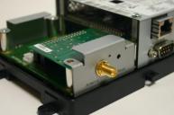
Only use Com1 option slot card position for the card
6

Basic Initial Design and Deployment Consideration
IMPORTANT: It is HIGHLY recommended that you do a proper field survey with the Viconics survey tools to establish connectivity limitations and architecture layout on ALL job sites considered for deployment with the Viconics wireless controller products. Please refer to the following manual for the survey procedures and tool usage: MAN VWG-SURVEY-Exx.
Please note that the following is well covered in the field survey tool procedure manual. A quick summary is provided here as a reference.
The Viconics wireless survey tools are intended to verify and validate the deployment and use of the Viconics wireless controllers on a potential job site.
The survey tool will display a numerical percentage value on the LCD screen which represents the wireless network ZigBee RSSI dBi value (Receiving Signal Strength Indicator).
Any value from 10 to 100% indicates good ZigBee connectivity.
Any value below 10% “may” indicate that an extra Router VRP 5000W1000W may need to be installed.
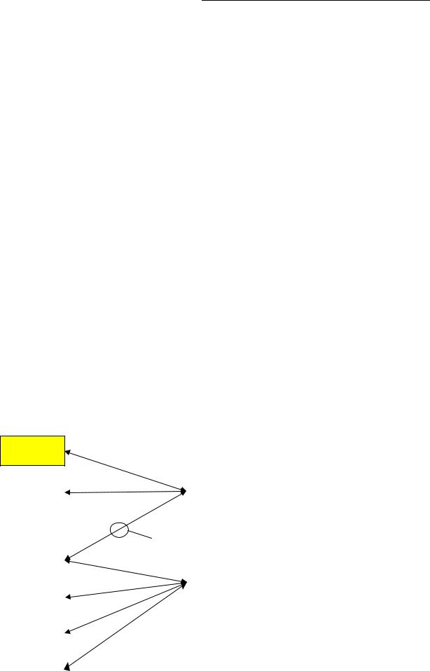
Knowing and understanding the 6A / 5H rule of ZigBee and how to cover orphan nodes!!!
ZigBee is a standard which is suitable for wireless sensor and controller networks. In ZigBee, a device / node / controller is said to join a network if it can obtain a ZigBee network address from a parent device. This ZigBee address is a value which is NOT initially exposed or available for the integrator to see.
Devices / nodes / controllers can calculate and assign addresses for their surrounding devices by a distributed address assignment scheme. This assignment is flexible, but it does somewhat restricts the number of attached devices and the possible depth of the said network for any given device on the network.
ZigBee supports three kinds of networks type: star, tree, and mesh networks. The ZigBee coordinator (In our case, this is the Jace with the wireless communication card) is responsible for initializing, maintaining, and controlling the network.
A star network has a coordinator with devices directly connecting to the coordinator.
A tree and mesh networks, devices can communicate with each other in a multi-hop fashion.
The network is formed by one ZigBee coordinator and multiple ZigBee routers. A device can join a network as an end device by the associating with the coordinator or a router.
A ZigBee device / node / controller is said to have successfully joined a network if it can obtain a ZigBee network address from the main Jace coordinator or any other router devices / nodes / controller.
6A stands for a maximum 6 addresses per device / node / controller.
7
Any given device / node / controller including the Jace –coordinator can ONLY give a maximum 6 ZigBee addresses out to other devices so they join the active ZigBee network. This means for any device / node / controller to be able to successfully join a ZigBee network, it needs an address to be assigned by another device / node / controller which is within connectivity and that has NOT already assigned its maximum of 6 addresses allowed.
Please note that once a device / node / controller has been assigned a ZigBee address & has joined the active ZigBee network, it will save its assigned ZigBee address to flash memory & re-use it afterwards even after a power failure or a network re-start. The ONLY time device / node / controller would require a NEW ZigBee address is if the network is re-started with either a new PAN ID or a new Channel value. This causes the currently assigned & saved ZigBee address in flash to be erased & will force the / node / controller to try to re-join a new network.
8
Orphan Nodes.
As such it is important to understand that HOW the network is first initially started up “may” create orphan unassigned devices / nodes / controllers that will seem to NOT want to join the ZigBee network. Let’s first understand how an orphan node is created. A typical example is when jobs are started on a technician desk before sending the devices / nodes / controllers in the field for installation. Often the integration technician will power the Jace – coordinator & connect it to the Workbench tool first creating & adding the WirelessTstatNetwork driver layer.
Once the WirelessTstatNetwork driver layer is up and running, they open & will start up the wireless devices / nodes / controllers one by one on their desk and add them to their Niagara database.
They will power the first unit, add it to the database & then power it down.
They will power the second unit, add it to the database & then power it down.
And so forth up to 6 devices maximum
This will work fine for 6 devices maximum, simply because the Jace – coordinator has filled its maximum 6 give away addresses. So when the technician powers up the 7th device / node / controller, it will NOT be able to join the ZigBee network…….unless one of the previous device
/ node / controller is powered back on also.
In order to add another 6 devices, one of the previously added devices needs to be left on. And so forth as the number of added devices / nodes / controllers grows. If 42 devices are to be added to the network, 8 of them should be ALWAYS powered & within connectivity range of all the others.
So how would orphan nodes appear I the field & how would you allow them to join the ZigBee network?
Please note again that this ONLY applies to the initial network start-up & that once all the devices are online to the Niagara database, everything will operate seamlessly even on power up / down & network re-starts.
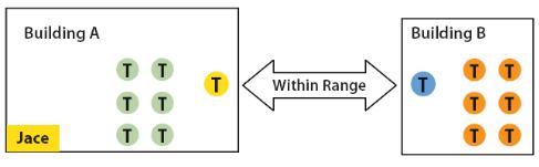
How Orphan nodes are created in the field. Ex.: 2 small buildings are within a few feet of each other. Both have 6+ devices / nodes / controller each.
A possible case for Building B orphan nodes is as follow: Building A is first stated & sets the Jace – coordinator configuration parameters for the PAN ID & Channel.
Premises:
Building A is first stated.
9

Yellow device / node / controller have given out its 6 addresses to other devices in building A.
Building B devices / nodes / controllers can only be connected through blue device /
nodes / controller due to maximum distance coverage.
Result:
Orange devices / nodes / controllers cannot join the ZigBee network.
Workaround to get orphan devices on the network:
Disconnect & bring one of building B device / node / controller & power it up in building A until it joins the ZigBee network ( confirmed either at the Jace – coordinator or using the status LED on the wireless communication card of the device / node / controller.
When the device / node / controller has joined the network in building A and is added to the Niagara database, bring it back into building B so it can propagate ZigBee addresses to the other devices in building B.
10
5H stands for 5 hops maximum recommended.
5H is for a simple process when laying out the architecture of the network. ANY given device / node / controller should be “optimized” to be NO FURTHER IF POSSIBLE than 5 Hops to & from the Jace / Coordinator. This is due to the nature of the Viconics ZigBee stack in the wireless controllers. To properly layout the potential architecture and determine the number of Jace’s required on the job site, you first need to establish the maximum possible coverage of a single Jace with a wireless communication card with a 5 hop maximum. This is also done with the survey tools & is covered in detail in the manual for the survey procedures and tool usage: MAN VWG-SURVEY-Exx.
Best practice ZigBee initial network start-up procedure
In order to avoid creating orphan devices / nodes/ controllers and moving about devices / nodes / controllers during the initial network start-up, it is recommended that you use the same power up sequence for devices as you originally did during the survey. Again, please note that once a device / node / controller has been assigned a ZigBee address and has joined the active ZigBee network, it will save its assigned ZigBee address to flash memory & re-use it afterwards even after a power failure or a network re-start. The ONLY time a device / node / controller would require a NEW ZigBee address is if the network is re-started with either a new PAN ID or a new Channel value. This causes the currently assigned & saved ZigBee address in flash to be erased and will force the / node / controller to try to re-join a new network. I.E. this is ONLY applicable during the initial network start-up.
11
12

Proper design considerations need to be addressed prior to any installation of a JACE with a Viconics wireless communication card and related wireless controllers.
Viconics recommends using a per floor horizontal architecture vs. a vertical one. Transmitting from one floor to the other may be possible in certain applications (such as going through stair ways), but the design and optimization of the controller antenna is designed for optimal horizontal distance penetration and not a vertical one. As such, be prepared to use AT LEAST ONE coordinator (VWG / Jace-Driver) per floor.
• Please note that radio transmissions CAN NOT travel through steel. If floors are constructed with steel joists or other steel materials it is highly unlikely that the wireless controller transmissions will be successful between floors.
1.To properly avoid network interference with 802.11 Wi-Fi devices in the 2.4GHz spectrum range, Viconics recommends the use of 802.15.4 channels 15, 25 and 26 only. 802.11 Wi-Fi transmissions overlap and may interfere with other channel selection allowed by 802.15.4 ( Channels 11 to 24 )
2.Maximum distance between each node ( controller ) should be:
Clear line of sight distance between 2 nodes should be under 100 feet ( 30 M )
13
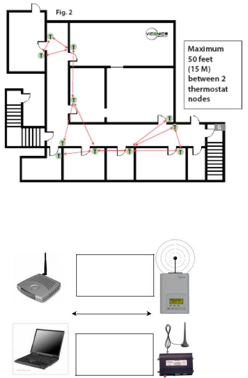
Non line of sight distance for typical gypsum wall partitions made with metal stud frame should be under 30 feet ( 10M )
3.Ensure that the minimum distance between any Viconics node and any Wi-Fi devices (wireless routers, wireless adapters, lap-tops using wireless networks, etc….) to be at least 3 foot (1 M) and preferably 10 feet (3 M) or more.
Minimum 3 feet (1 M) between Wi-Fi equipment and Viconics wireless devices
Preferably 10 feet (3 M) or more between Wi-Fi equipment and Viconics wireless devices
14
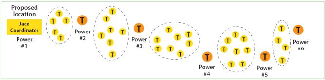
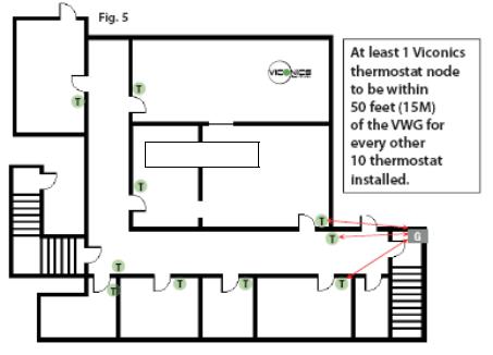
4.Ensure that at least one controller is within 30 feet of the VWG for every cluster of 10 controllers installed.
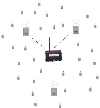
5.Always try to locate if possible the VWG near the center of all associated wireless controllers.
6.Always try to locate the VWG near on in line of sigh to as many wireless controllers as possible.
7.Try to avoid metal, brick walls or concrete obstructions between wireless devices as much as possible.
8.Make sure the antenna on the VWG is always perpendicular to the floor.
9.Avoid placing VWG and controllers near metal or enclosed in metal boxes. If the VWG needs to be installed inside a metal cabinet, use the remote antenna accessory.
Ex. For a recommended maximum of 30 wireless controllers total per JACE, a minimum of 3 of them should be within 30 feet (9 M) of the VWG range.
15
50 feet (15 M)
16
JACE and Wireless Communication Card Configuration
Initial Configuration Note: The following instructions assume you are familiar with the AX workbench environment and its related functions:
Install the wireless communication card as stipulated by the instructions provided with the wireless card
Copy the “WirelessTstatNetwork” and “WirelessTstatDevices” jar files to your local AX Workbench module folder
Using the Software Manager, add the “WirelessTstat” jar file to the target JACE with the wireless communication card already installed
Re-boot both the local AX Workbench interface and the JACE itself to properly load the “WirelessTstatNetwork” jar modules
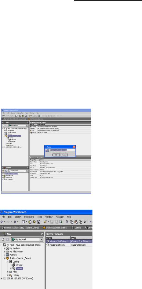
Using the “WirelessTstat” palette tool or the add network tool, simply drag & drop the “WirelessTstatNetwork” driver under the local driver folder of the JACE
Rename the “WirelessTstatNetwork” driver extension name if required.
17
18

Right hand click the “WirelessTstatNetwork” driver to load the network property sheet
Under the Serial Port Configuration, set Port Name to “COM1”. Only COM1 can be used with the wireless communication card since hardware flow control is required. All other properties are locked and set as read only
Set the ZigBee wireless communication card options.
19
20
VWG ZigBee Settings
Those settings are where you set the ZigBee PAN ID (Personal Area Network Identification) address and the channel for the wireless communication card.
Gateway ZigBee PAN ID. (Personal Area Network Identification). This is where the PAN
ID of the gateway is set. Range is from address 1 to 500. The default of “0” is not a valid PAN ID.
Channel Select. This is where the current Channel frequency used by the gateway is set. Range is from 11 to 26. ( 2405 MHz to 2480 MHz, 5 MHz channel spacing ) Please note that channel 26 is attenuated by 4 db compared to the other channels. The default of “10” is not a valid Channel.
Viconics highly recommends the use of 802.15.4 channels 15, 25 and 26 only. 802.11 Wi-Fi transmissions overlap and “may” interfere with other channel selection allowed by 802.15.4 ( Channels 11 to 14 & 16 to 24 )
IEEE Address. Individual unique IEEE address for any ZigBee device on the network. Factory assigned & non-editable.
Zigbee Address. Individual unique ZigBee address for any ZigBee device on ANY INDIVIDUAL ZigBee network. The address is assigned during the initial network start-up & saved in flash memory. This is the main address used for all key low level network functions.
Please note that the communication module information and the assigned IEEE & ZigBee wireless address information are given for information references only.
It is important to click on the “SAVE” button for the new wireless parameters to take effect and the wireless network to properly start.
Any time the PAN ID or Channel is changed, a new ZigBee address is assigned by the network manager to the devices.
IMPORTANT NOTES (Please Read Carefully):
Viconics recommends using a per floor horizontal architecture vs. a vertical one. Transmitting from one floor to the other may be possible in certain applications (such as going through stair cases), but the design and optimization of the controller antenna is designed for optimal horizontal distance penetration and not a vertical one. As such, be prepared to use AT LEAST ONE coordinator (Jace-Driver) per floor.
Please note that radio transmissions CANNOT travel through steel. If floors are constructed with steel joists or other steel materials it is highly unlikely that the wireless controller transmissions will be successful between floors.
A “recommended” typical maximum of:
o 30 network able controllers can be supported by a single JACE2. o 50 network able controllers can be supported by a single JACE6.
oBe sure you set the SAME PAN ID and Channel value at both the gateway and the controller(s).
21
 Loading...