


ELECTRONIC THERMOSTAT: C1025 FOR MODULATING ELECTRIC HEAT APPLICATIONS
0 to 10 Vdc modulating output Vdc pulsed modulating output
Room or supply control applications
DESCRIPTION
The C1025 series thermostats are microcomputer-based, proportional and integral (PI) devices with one analog 0 to 10 Vdc output and one Vdc time proportioning pulsed output.
The analog 0 to 10 Vdc modulating output can control the room or supply temperature by modulating directly a 0 to 10 Vdc SCR power controller.
The Vdc pulsed output can control the room or supply temperature by modulating directly 4-32 Vdc triggered solid state relays ( SSR’s ) using a time proportioning control algorithm on a 1 second time cycle.
The thermostats also contain two dip switch which adjust the following parameters :
•Room or supply control applications
•Internal or external remote sensor
Type of output |
Modulating devices for heating |
|
|
|
|
Modulating analog |
SCR’s power controls |
|
0 to 10 Vdc output |
||
|
||
Vdc pulsed output |
4-32 Vdc triggered SSR’s |
HOW TO ORDER
C1025 -
↓
01 = °F scale
↓
02 = °C scale
Notes: Order remote S61 sensors separately.
Vertical covers are standard.
DIMENSIONS
|
BASE |
90 |
1.275" |
|
80 |
|
32 mm |
WIRING |
70 |
F |
2.8" |
|
60 |
|
( 71 mm ) |
FROM TOP |
50 |
4.5" |
|
|
3.275" |
|
|
OR FROM BACK |
( 83 mm ) |
|
( 114 mm ) |
|
|
|
|
SECURITY SCREW |
|
|
|
SPECIFICATIONS
Operating Conditions: -30 °C to 50 °C ( -22 °F to 122 °F ) 0% to 95% R.H. non-condensing
Sensor: Local 47 K NTC thermistor Resolution: ± 0.1 °C ( ± 0.2 °F )
Control accuracy: ± 0.2 ° C ( ± 0.4 °F ) ( calibrated )
Ranges: C1025-02: 10 °C to 32 °C
C1025-01: 50 °F to 90 °F
Proportional band for room
temperature control ( S1 = 0 ): 1.8°C ( 3.2°F ) Proportional band for supply
temperature control ( S1 = 1 ): 28°C ( 50°F )
Analog 0 to 10 Vdc output: 0 to 10 Vdc into 2KΩ resistance min. 5 mA max at 10 Vdc
Vdc pulsed output: 20 mA max at 8 Vdc.
Power: 24 Vac -15%, +10% 50/60 Hz; 2 VA
LIT-C1025-E03 |
1 |
ANALOG 0 TO 10 Vdc MODULATING OUTPUT
The analog 0 to 10 Vdc modulating output can control the room or supply temperature by modulating directly 0 to 10 Vdc SCR power controller.
Use only one of the output, not both at the same time.
Vdc PULSED MODULATING OUTPUT
The Vdc pulsed output can control the room or supply temperature by modulating directly 4-32 Vdc triggered solid state relays ( SSR ) using a time proportioning control algorithm on a 1 second time cycle.
Ex.:
PI |
Time on |
Time off |
Total |
demand |
|
|
cycle |
50 % |
½ sec. |
½ sec. |
1 sec. |
25 % |
¼ sec. |
¾ sec. |
1 sec. |
This time proportioning output cannot be used on regular mechanical relays or contactors.
Use only one of the output, not both at the same time
REMOTE SENSOR
A remote sensor can be wired and used with the C1025 thermostat. To wire a remote sensor, first set dip switch S2 to position 0 ( off ).
If the application is for discharge air or supply temperature control, set dip switch S1 to position 1 ( on ). This will enable a larger proportional band, making the controlled temperature more stable.
Characteristics of remote sensor 47 KΩ ( S61 ).
Temperature °F |
Temperature °C |
Sensor resistance |
||
150.0 |
°F |
65.6 |
°C |
9.610 Kohm |
140.0 |
°F |
60.0 |
°C |
11.700 Kohm |
130.0 |
°F |
54.4 |
°C |
14.342 Kohm |
120.0 |
°F |
48.9 |
°C |
17.682 Kohm |
110.0 |
°F |
43.3 |
°C |
21.940 Kohm |
100.0 |
°F |
37.8 |
°C |
27.412 Kohm |
90.0 |
°F |
32.2 |
°C |
34.483 Kohm |
80.0 |
°F |
26.7 |
°C |
43.704 Kohm |
70.0 |
°F |
21.1 |
°C |
55.834 Kohm |
60.0 |
°F |
15.6 |
°C |
71.866 Kohm |
50.0 |
°F |
10.0 |
°C |
93.340 Kohm |
40.0 |
°F |
4.4 |
°C |
122.298 Kohm |
THERMOSTAT INSTALLATION
Important.
Electronic controllers require special care for wiring and startup. To avoid problems, carefully follow the procedures below.
Be sure to have all the literature on hand for all components
installed: controller, actuators, relay, etc...
Look at the wiring diagrams, and study them carefully. Be sure that you understand how the system is supposed to work.
Make the wiring according to the wiring diagrams. Respect polarity for power terminals # 3 & # 4 between multiple controllers if the same transformer is used.
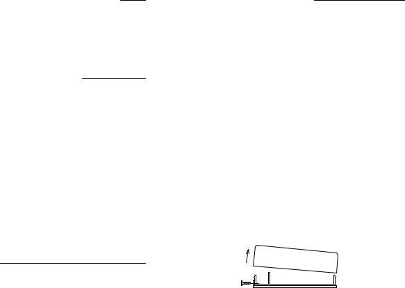
•Remove security screw on left side of thermostat cover.
•Open up by pulling on the bottom side of thermostat.
A)Location:
1- Shouldn’t be installed on outside wall.
2- Must be installed away from any heat source. 3- Shouldn’t be affected by direct sun radiation.
4- Nothing must restrain vertical air circulation to the thermostat.
B)Installation:
1- Pull out cables 6” out of the wall. 2- Wall surface must be flat and clean.
3- Separate the thermostat and the base by pulling the cover by the bottom (same as the security screw.)
4- Insert cable in the central hole of the base.
5- Align the base and mark the location of the two mounting holes on the wall. Install proper side of base up.
6- Install shields in the wall.
7- Insert screws in mounting holes on each side of the base. DO NOT OVERTIGHTEN!
8- Strip each wire 1/4 inch.
9- Insert each wire according to wiring diagram.
10Reinstall the cover ( top side first ) and gently push back extra wire length in the hole in the wall.
11Install security screw.
2
 Loading...