

Page 1
Page 2
TS, MICROBLENDER, HI/LO FLOW
1.0 SCOPE
This document defines a general test procedure that when used with the
specific Data Recording Sheet, (DRS) for the device under test, demonstrates
that (the Unit-in-test) it conforms to all product performance specifications and
requirements.
2.0 BACKGROUND
In addition to capturing pertinent data, the DRS is a test matrix containing specific
test parameters for the device being tested. All functional parameters stated in the
Device Specification are contained in the DRS. Although there are many
hardware configurations allowing for a variety of inlet and outlet adaptations, the
fundamental functional components, and sub-assemblies are common among the
Bird Microblender models. Several variations of the standard configuration are
available with "Primary" outlet ports located either at the bottom or on the left side,
with primary, auxiliary, and supply gas fittings customized (OEM) and with some
functional variations. Functional variations are detailed on corresponding DRSs.
DRSs are listed on the top level drawing and/or on the MINX network.
TEST STANDARD
3.0 APPLICABLE DOCUMENTS
3.1 Applicable DRS for the device under test.
3.2 Documents 91600, 91058 and 91059
3.3 Blender Re-processing Guide, 90636
4.0 GENERAL
4.1 Prior to testing, visually inspect the blender assembly to verify its
conformance to the blender assembly drawing and to aesthetic
requirements.
4.2 The unit to be tested must have been previously calibrated and the
"alarm/bypass" adjusted sufficient to prevent bypass leakage. Refer to
Manufacturing Assembly Guides, (MAG) 91600, 91058 and 91059 for precalibration, calibration and checkout details.
4.3 Re-processing (includes rework and re-test) of product is explained in
document 90636.
THIS DOCUMENT IS THE COPYRIGHTED PROPERTY
OF VIASYS
AND MAY NOT BE REPRODUCED WITHOUT WRITTEN
PERMISSION OR USED FOR PURPOSES OTHER THAN
VIASYS
AUTHORIZED PURPOSES.
TM
HEALTHCARE-CRITICAL CARE DIVISION
TM
HEALTHCARE-CRITICAL CARE DIVISION
DWG SIZE NO.
A
DWG NO.
⎢
90503
SHEET 2 OF 11
REV.
⎢
G
Page 3
TS, MICROBLENDER, HI/LO FLOW
Q
5.0 TEST SETUP AND EQUIPMENT REQUIREMENTS
5.1 EQUIPMENT/MATERIALS REQUIREMENTS
No. Description Min. Range/Acc'y Suggested Mfg. Model/ID. No.
1. Unit-in-Test, "Microblender" TYPE 3800
4. oxygen analyzer
5. pressure gage;
6. pressure gage;
flow meter; Q1-A (direct reading)
flow meter; Q1-B (direct reading)
flow meter; Q1-C (direct reading)
flow meter; Q2 (direct reading)
"bubble jar" N/A
Leak Test Fixture N/A N/A A01721
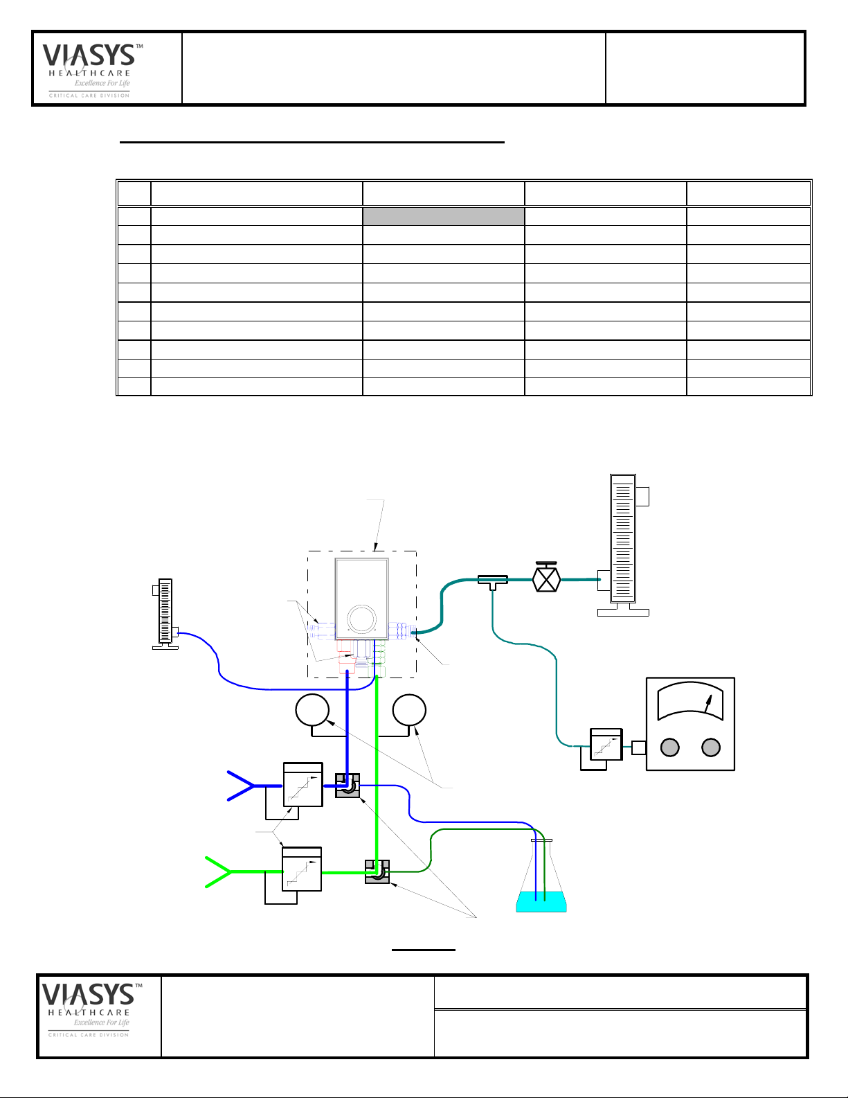
5.2 SCHEMATIC, TEST SET-UP IN LIEU OF BIRD STANDARD BLENDER
TEST FIXTURE:
0 to 100%, ± .1%
0 to 100 Psi ± 1%
0 to 100 Psi, ± 1%
0 to 15 Lpm, ± 4% FS
0 to 35 Lpm, ± 4% FS
20-140 Lpm, ± 4% FS
0 to 15 Lpm, ± 4% FS
TEST STANDARD
SYBRON, "Servomex" Mod 570A
Ashcroft, US Gage, etc.
Ashcroft, US Gage, etc.
or equiv.
or equiv.
Fisher & Porter or equiv.
Fisher & Porter or equiv.
1
Q2
OUTLET PORTS
"Bleed Flow"
AIR
SUPPLY
SUPPLY PRESSURE REGULATORS
O2
SUPPLY
"PRIMARY"
UNIT-IN-TEST
P
AIR
FLOW CONTROL
VALVE
MAIN FLOW
Q1-A: 0-15 LPM
Q1-B: 0-35 LPM
Q1-C: 20-220 LPM
AUXILLIARY OUTLET
P
O2
PRESSURE GAGES
BUBBLE JAR
(ref, "Leak Test")
(~.1 Lpm @ 2 Psig)
OXYGEN ANALYZER
% O2
THREE-WAY VALVES
(OR EQUIVALENT)
FIGURE 1
THIS DOCUMENT IS THE COPYRIGHTED PROPERTY
OF VIASYS
AND MAY NOT BE REPRODUCED WITHOUT WRITTEN
PERMISSION OR USED FOR PURPOSES OTHER THAN
VIASYS
AUTHORIZED PURPOSES.
TM
HEALTHCARE-CRITICAL CARE DIVISION
TM
HEALTHCARE-CRITICAL CARE DIVISION
DWG SIZE NO.
A
DWG NO.
⎢
90503
SHEET 3 OF 11
REV.
⎢
G
Page 4

TS, MICROBLENDER, HI/LO FLOW
TEST STANDARD
SET-UP NOTES: (Refer to Figure 1)
1. Verify calibration of the test station O2 analyzer at 21% and 100% on a daily
(minimum) basis.
2. Install the UNIT-IN-TEST in the test system per Figure 1. Note; standard units
(e.g., 03800A) with a bottom located primary outlet are automatically
connected at the primary when installed in the fixture.
If the Microblender is fitted with an auxiliary outlet fitting, connect that fitting to
the auxiliary outlet hose on the test station. Keep all Microblender outlets
connected to the test station throughout the test unless otherwise directed.
3. Apply 50 Psig (AIR) to the air inlet and 50 Psig (O
) to the oxygen inlet.
2
4. For testing Microblenders with flow meters (“UltraBlenders”), hook up the
inputs to the Microblender in the normal manner to the test station. Connect
the outlet being tested directly to the Oxygen Analyzer via a tubing assembly
equivalent to that shown in Figure 2. Leave the opposite outlet disconnected
(no hose).
Adjust the flow to the required amount using the flow meter on the
Microblender outlet being tested.
It may be necessary to run the pump on the Oxygen Analyzer to supply it with
adequate gas during the tests.
Figure 2
Outlet Tubing Assy. for UltraBlenders
THIS DOCUMENT IS THE COPYRIGHTED PROPERTY
OF VIASYS
AND MAY NOT BE REPRODUCED WITHOUT WRITTEN
PERMISSION OR USED FOR PURPOSES OTHER THAN
VIASYS
AUTHORIZED PURPOSES.
TM
HEALTHCARE-CRITICAL CARE DIVISION
TM
HEALTHCARE-CRITICAL CARE DIVISION
DWG SIZE NO.
A
DWG NO.
⎢
90503
SHEET 4 OF 11
REV.
⎢
G
Page 5

TS, MICROBLENDER, HI/LO FLOW
6.0 PERFORMANCE TEST - PROCEDURE AND REQUIREMENTS
After installing the UNIT-IN-TEST in the test fixture, connect outlets as directed on
DRS with flow directed to appropriate flow meter.
6.1 BLEED FLOW
STEP 1:
a. Install the bleed flow measurement adapter over the bleed outlet.
b. Read and record the indicated bleed flow on flow meter Q2, then
remove the measurement apparatus.
Requirement: Refer to DRS of device being tested.
TEST STANDARD
6.2 CALIBRATION CHECK:
Troubleshooting Guide, for calibration troubleshooting information.
Redirect the flow from auxiliary to primary port and direct flow to flow meter
Q1-B. Adjust the flow control valve until the flow rate stated on DRS is
obtained.
STEP 2: Left end-point
a. Adjust the blender control knob to the left end-stop (21%) and allow the
oxygen analyzer to stabilize (≈10 sec).
b. Read the test analyzer and record the indicated oxygen percentage.
Requirement: The O2 Analyzer displays the range indicated on the DRS.
STEP 3: Right end-point
a. Adjust the blender control knob to the right end-stop (100%) and allow
the oxygen analyzer to stabilize.
b. Read and record the indicated oxygen percentage.
Requirement: The O
Analyzer displays the range indicated on the DRS.
2
6.3 SET-POINT ACCURACY
Refer to Appendix A, Pre-Cal and Calibration
(Both gas supply pressures @ 50 Psig)
STEP 4: 30% Graduation
a. Adjust the blender control knob to the center of the 30% graduation
mark and allow the oxygen analyzer to stabilize.
b. Read and record the indicated oxygen percentage on the analyzer.
Requirement: The O2 Analyzer displays the range indicated on the DRS.
STEP 5: 90% Graduation
a. Adjust the blender control knob to the center of the 90% graduation
mark and allow the oxygen analyzer to stabilize.
THIS DOCUMENT IS THE COPYRIGHTED PROPERTY
OF VIASYS
AND MAY NOT BE REPRODUCED WITHOUT WRITTEN
PERMISSION OR USED FOR PURPOSES OTHER THAN
VIASYS
AUTHORIZED PURPOSES.
TM
HEALTHCARE-CRITICAL CARE DIVISION
TM
HEALTHCARE-CRITICAL CARE DIVISION
DWG SIZE NO.
A
DWG NO.
⎢
90503
SHEET 5 OF 11
REV.
⎢
G
Page 6

TS, MICROBLENDER, HI/LO FLOW
b. Read and record the indicated oxygen percentage on the analyzer.
Requirement: The O2 Analyzer displays the range indicated on the DRS.
STEP 6: 60% Graduation
a. Adjust the blender control knob to the center of the 60% graduation
mark and allow the oxygen analyzer to stabilize.
b. Read and record the indicated oxygen percentage on the analyzer.
Requirement: The O2 Analyzer displays the range indicated on the DRS.
6.4 FLOW STABILITY
Without changing the blender control knob, redirect outlet flow from the
Primary to the Auxiliary port. Adjust flow meter Q1-B to 0 (zero). Set the
flowmeter Q1-A to DRS value.
STEP 7: Stability at 60%
a. Adjust flow meter Q1-A (0-15 Lpm) to obtain stated DRS flow from the
auxiliary outlet.
TEST STANDARD
b. Allow the oxygen analyzer to stabilize (≈ 20 sec.), then read and record
the indicated oxygen percentage.
Requirement: The O2 Analyzer displays the DRS value.
STEP 8: 30% Check-point
a. Adjust the blender control knob to the center of the 30% graduation
mark and allow the oxygen analyzer to stabilize.
b. Read and record the indicated oxygen percentage on the analyzer.
Requirement: The O2 Analyzer displays the range indicated on the DRS.
STEP 9: 90% Check-point
a. Adjust the blender control knob to the center of the 90% graduation
mark and allow the oxygen analyzer to stabilize.
b. Read and record the indicated oxygen percentage on the analyzer.
Requirement: The O
Analyzer displays the range indicated on the DRS.
2
6.5 PRESSURE STABILITY
STEP 10: 60% Set-point
a. Direct the flow from the Primary port to flowmeter Q1-B. Set flow meter
Q1-A to 0 (zero). Adjust (Q1-B) flow meter to DRS value. Set the
blender control knob to the center of the 60% graduation and allow the
analyzer to stabilize.
THIS DOCUMENT IS THE COPYRIGHTED PROPERTY
OF VIASYS
AND MAY NOT BE REPRODUCED WITHOUT WRITTEN
PERMISSION OR USED FOR PURPOSES OTHER THAN
VIASYS
AUTHORIZED PURPOSES.
TM
HEALTHCARE-CRITICAL CARE DIVISION
TM
HEALTHCARE-CRITICAL CARE DIVISION
DWG SIZE NO.
A
DWG NO.
⎢
90503
SHEET 6 OF 11
REV.
⎢
G
Page 7

TS, MICROBLENDER, HI/LO FLOW
TEST STANDARD
b. Read and record the indicated oxygen percentage on the analyzer.
Requirement: The O2 Analyzer displays the range indicated on the DRS.
STEP 11: PRESSURE IMBALANCE - P
a. Adjust the Air supply pressure regulator to stated DRS value.
b. Allow the oxygen analyzer to stabilize, then read and record the
indicated oxygen percentage.
Requirement: The O
Analyzer displays the range indicated on the DRS.
2
STEP 12: PRESSURE IMBALANCE - P
a. Adjust the Air pressure regulator to stated DRS value.
b. Allow the oxygen analyzer to stabilize, then read and record the
indicated oxygen percentage.
Requirement: The O2 Analyzer displays the range indicated on the DRS.
6.6 ALARM/BYPASS OPERATION
STEP 13: "Low AIR" Alarm Actuation
a. Gradually reduce Air supply pressure until the blender alarm sounds.
b. Record the air pressure at which point the alarm sounds.
Requirement: With O2 at DRS stated value, the alarm must sound
when Air pressure drops to the value indicated on the DRS.
AIR
AIR
> P
< P
O2
O2
STEP 14: "Low AIR" Alarm Reset
a. Gradually increase Air supply pressure until the blender alarm stops.
b. Observe and record the air pressure at which point the alarm stops.
Requirement: The alarm resets at or before Air supply pressure indicated
on the DRS.
c. Re-adjust the Air supply pressure to DRS stated value.
STEP 15: "Low O2" Alarm Actuation
a. Gradually reduce Oxygen supply pressure until the blender alarm
sounds.
b. Record the O
pressure at which point the alarm sounds.
2
Requirement: With Air set a DRS value, the alarm must sound when O2
pressure drops to DRS stated value.
THIS DOCUMENT IS THE COPYRIGHTED PROPERTY
OF VIASYS
AND MAY NOT BE REPRODUCED WITHOUT WRITTEN
PERMISSION OR USED FOR PURPOSES OTHER THAN
VIASYS
AUTHORIZED PURPOSES.
TM
HEALTHCARE-CRITICAL CARE DIVISION
TM
HEALTHCARE-CRITICAL CARE DIVISION
DWG SIZE NO.
A
DWG NO.
⎢
90503
SHEET 7 OF 11
REV.
⎢
G
Page 8

TS, MICROBLENDER, HI/LO FLOW
STEP 16: "Low O2" Alarm Reset
a. Gradually increase Oxygen supply pressure until the blender alarm
stops.
b. Observe and record the O2 pressure at which point the alarm stops.
Requirement: The alarm resets at or before Air supply pressure reaches
DRS stated value.
c. Re-adjust the Oxygen supply regulator to DRS stated value.
6.7 FLOW CAPACITY
Notes:
1. If the test station being used to conduct this test is not equipped with a
20 to 220 Lpm flow meter, the UIT must be relocated to a station with a
flow meter of this capacity in order to conduct the following tests.
2. The following tests (Steps 17 through 22) may be conducted with air
only applied to both gas inlets.
TEST STANDARD
STEP 17: Auxiliary Outlet - Unrestricted Flow (with both Gas Supplies
@ DRS stated value).
a. Turn off gas supplies to both the Air and O2 inlets. Connect a hose from
the Auxiliary outlet directly to the flow meter (ref., Q1-C).
b. Turn both gas supplies back on, then observe and record the flow rate
at flow meter Q1-C.
Requirement: The flow rate from the Auxiliary outlet must be within the
value stated on the DRS.
c. Turn off gas supplies to both the Air and O2 inlets. Disconnect the hose
from the Auxiliary outlet and reconnect to the Primary outlet.
STEP 18: Primary Outlet - Unrestricted Flow (with both Gas Supplies
@ DRS stated value).
a. Turn both gas supplies back on.
b. Observe and record the flow rate at flowmeter Q1-C.
Requirement: The flow rate from the Primary outlet must be within DRS
stated value.
c. Turn off gas supplies to both the Air and O
inlets.
2
STEP 19: Bypass Flow, Loss of Air Supply
Shut off the gas supply to Air inlet. Turn the O2 gas supply on. Verify it is
set at the DRS stated value. Record the flow rate at flow meter Q1.
THIS DOCUMENT IS THE COPYRIGHTED PROPERTY
OF VIASYS
AND MAY NOT BE REPRODUCED WITHOUT WRITTEN
PERMISSION OR USED FOR PURPOSES OTHER THAN
VIASYS
AUTHORIZED PURPOSES.
TM
HEALTHCARE-CRITICAL CARE DIVISION
TM
HEALTHCARE-CRITICAL CARE DIVISION
DWG SIZE NO.
A
DWG NO.
⎢
90503
SHEET 8 OF 11
REV.
⎢
G
Page 9

TS, MICROBLENDER, HI/LO FLOW
Requirement: With only the Oxygen supply pressure set at DRS stated
value; the flow rate from the Primary outlet must be within the stated DRS
value.
STEP 20: Bypass Flow, Loss of O2 Supply
a. Return the Air supply pressure to stated DRS value. During bypass
Flow test the outlet flow must be restricted to ~ 80LPM for P/N 11329.
b. Shut off the gas supply to Oxygen inlet. Observe and record the flow
rate at flow meter Q1.
Requirement: With only the Air supply pressure at stated DRS value, the
flow rate from the Primary outlet must be within the DRS stated value.
6.8 REVERSE FLOW CHECKING
STEP 21: Reverse Flow, Air to Oxygen
a. Reduce both gas supply pressures to 0 (zero) Psig by adjusting the
regulators.
TEST STANDARD
b. Adjust the toggle valve on the oxygen supply line to direct any reverse
flow to the "bubble" jar.
c. Gradually increase the air supply pressure to DRS stated value.
Observe the bubble jar and count the bubbles (if any) for 30 seconds.
Record the results of the count. Note, worst case leak may occur at
some point before reaching DRS stated value.
Requirement: 1 bubble or less in a 30 sec. period.
STEP 22: Reverse Flow, Oxygen to Air
a. Reduce the Air supply pressure to 0 (zero) Psig and adjust the toggle
valve on the air supply line to direct any reverse flow to the "bubble" jar.
b. Adjust the toggle valve on the oxygen supply side to reopen the supply
line.
c. Gradually increase the oxygen supply pressure to DRS stated value.
Observe the bubble jar and count the bubbles (if any) for 30 seconds.
Record the results of the count.
Requirement: 1 bubble or less in a 30 sec. period.
6.9 LEAK TEST
Note: The leak test must be performed after all adjustments are done (after
calibration process) and should be recorded on the applicable DRS.
a. Unless the auxiliary output port (near Muffler) receives a no-bleed fitting,
plug this port with P/N 20151 cap and P/N 00193 O-ring for the leak test.
Install the appropriate fitting (s) after the leak is complete.
THIS DOCUMENT IS THE COPYRIGHTED PROPERTY
OF VIASYS
AND MAY NOT BE REPRODUCED WITHOUT WRITTEN
PERMISSION OR USED FOR PURPOSES OTHER THAN
VIASYS
AUTHORIZED PURPOSES.
TM
HEALTHCARE-CRITICAL CARE DIVISION
TM
HEALTHCARE-CRITICAL CARE DIVISION
DWG SIZE NO.
A
DWG NO.
⎢
90503
SHEET 9 OF 11
REV.
⎢
G
Page 10

TS, MICROBLENDER, HI/LO FLOW
TEST STANDARD
b. Attach air and oxygen fitting of the blender to the leak test fixture to
perform the leak test.
c. Open the ball valve of the leak test fixture and adjust the pressure to 50.0
± .1 psi.
d. Close the ball valve and observe the pressure for two minutes
e. Follow the appropriate action:
• If the pressure drop was no more than two psi in two minutes (one psi
per minutes) proceed with any remaining testing.
• If the pressured drop was more than two psi in two minutes, use
“snoop” to locate the leak and repair the blender according. Then
verify the repair(s) by repeating the above leak test.
THIS DOCUMENT IS THE COPYRIGHTED PROPERTY
OF VIASYS
AND MAY NOT BE REPRODUCED WITHOUT WRITTEN
PERMISSION OR USED FOR PURPOSES OTHER THAN
VIASYS
AUTHORIZED PURPOSES.
TM
HEALTHCARE-CRITICAL CARE DIVISION
TM
HEALTHCARE-CRITICAL CARE DIVISION
DWG SIZE NO.
DWG NO.
⎢
A
SHEET 10 OF 11
90503
REV.
⎢
G
Page 11

TS, MICROBLENDER, HI/LO FLOW
APPENDIX A
PRE-CAL & CALIBRATION TROUBLESHOOTING GUIDE
Ι. Blender Accuracy Performance Check
Perform the following routine when end-stop accuracies are in specification but 30’s /
60’s or 90’s are out.
1. Offset blender supply pressures to 40/50 psig or as stated on DRS.
2. Begin at left end stop with primary flow set 14-15 lpm maximum.
3. Select 30%. If the FIO2 is out of tolerance increase the flow to 40-50 lpm. Note
the difference in FIO2 when flow is increased.
4. Repeat step 3 (always start at 14-15 lpm flow) selecting 60% or 90%
respectively. Note the difference in FIO2 when flow is increased.
5. Significant changes in FIO2 accuracies (changes by 1.0-2.0% O2 concentration)
when flows are increased indicate front or rear balance blocks are not functioning
normally.
TEST
STANDARD
6. Begin by inverting front balance block and retesting steps 2-5. The rear set of
balance blocks may also be inverted to determine their contribution to the overall
performance. Also front may be interchanged with rear and the test repeated.
7. By substituting an alternate balance block and retesting, a further determination
can be made. Front seat/stem or rear seat/poppet replacements should be made
only when end-stop accuracies cannot be attained, or when 03892 and front/rear
seat interact resulting in multiple performance problems.
THIS DOCUMENT AND ITS CONTENTS (THIS “DOCUMENT”) ARE CONFIDENTIAL AND ARE
NOT TO BE DISSEMINATED TO THIRD PARTIES. THIS DOCUMENT IS THE EXCLUSIVE
COPYRIGHTED PROPERTY OF VIASYS HEALTHCARE’S RESPIRATORY CARE BUSINESS
UNIT AND MAY NOT BE REPRODUCED OR DISTRIBUTED, IN WHOLE OR IN PART, WITHOUT
ITS PRIOR WRITTEN PERMISSION OR USED FOR PURPOSES OTHER THAN AS EXPRESSLY
AUTHORIZED.
ES 5.1-2 (1/05)
DWG SIZE:
A
DRAWING NUMBER:
90503
SHEET: 11 OF 11
REV.
G
 Loading...