

Page 1

Operator’s Manual
Infant Flow
Advance™ System
E.M.E. (Electro Medical Equipment) Ltd.
A subsidiary of VIASYS Healthcare inc.
© Copyright 2004, VIASYS Healthcare Critical Care
777077-101 Revision B June 2004
Page 2

2 Infant Flow Advance™ System
Revision History
Date Revision Pages Changes
December 2003 A All Release
June 2004 B All Release manual in VIASYS Healthcare
template using VIASYS Healthcare Critical
Care nomenclature. Add Appendix C,
Abdominal Respiratory Sensor Placement.
Revise part number list in Appendix B.
777077-101 Revision B June 2004
Page 3

Operator’s Manual 3
Contact and Ordering Information
United States, Latin America, Asia Pacific:
Sales, Service and Clinical Support:
VIASYS Healthcare
Critical Care Division
22705 Savi Ranch Parkway
Yorba Linda, CA 92887
Phone: (714) 283-8444
(800) 381-3552
Fax: (714) 283-8493
www.VIASYShc.com
United Kingdom:
Sales, Service and Clinical Support:
VIASYS Healthcare
3 Welton Rd.
Warwick,
CV34 5PZ
Phone: 01926 490888
Fax: 01926 402262
Europe
Sales and Customer Service Technical Service
VIASYS Healthcare VIASYS Healthcare
Critical Care Division Leibnizstrasse 7
22705 Savi Ranch Parkway D-97204 Hoechburg
Yorba Linda, CA 92887 Germany
Phone: (714) 283-8444 Phone +49 (0) 931 4972 – 0
(800) 381-3552 Fax:+49 (0) 931 4972 –423
e-mail: Support.CC.EU@VIASYShc.com
website: www.VIASYShc.com
777077-101 Revision B June 2004
Page 4

4 Infant Flow Advance™ System
CAUTION
Federal law (USA) restricts this device to sale by or on the order of a physician.
CAUTION
Not suitable for use in the presence of flammable anesthetics.
CAUTION
Always read the Operator’s Manual before applying treatment.
CAUTION
The Infant Flow Advance™ has been designed and tested as a complete system
using Infant Flow™ accessories. Use only approved accessories (Refer to Appendix
B for a list of approved accessories).
CAUTION
Service and/or repair of this instrument is restricted to VIASYS Healthcare authorized
or VIASYS Healthcare Trained Personnel only.
777077-101 Revision B June 2004
Page 5

Operator’s Manual 5
Warranty
The Infant Flow Advance is warranted to be free from defects in material and
workmanship and to meet the published specifications for One (1) year from date of
shipment.
The liability of VIASYS Healthcare, Critical Care Division, (referred to as the
Company) under this warranty is limited to replacing, repairing or issuing credit, at
the discretion of the Company, for parts that become defective or fail to meet
published specifications during the warranty period; the Company will not be liable
under this warranty unless (A) the Company is promptly notified in writing by Buyer
upon discovery of defects or failure to meet published specifications; (B) the
defective unit or part is returned to the Company, transportation charges prepaid by
Buyer; (C) the defective unit or part is received by the Company for adjustment no
later than four weeks following the last day of the warranty period; and (D) the
Company’s examination of such unit or part shall disclose, to its satisfaction, that
such defects or failures have not been caused by misuse, neglect, improper
installation, unauthorized repair, alteration or accident.
Any authorization of the Company for repair or alteration by the Buyer must be in
writing to prevent voiding the warranty. In no event shall the Company be liable to
the Buyer for loss of profits, loss of use, consequential damage or damages of any
kind based upon a claim for breach of warranty, other than the purchase price of any
defective product covered hereunder.
The Company warranties as herein and above set forth shall not be enlarged,
diminished or affected by, and no obligation or liability shall arise or grow out of the
rendering of technical advice or service by the Company or its agents in connection
with the Buyer's order of the products furnished hereunder.
Limitation of Liabilities
This warranty does not cover normal maintenance such as cleaning, adjustment or
lubrication and updating of equipment parts. This warranty shall be void and shall not
apply if the equipment is used with accessories or parts not manufactured by the
Company or authorized for use in writing by the Company or if the equipment is not
maintained in accordance with the prescribed schedule of maintenance.
The warranty stated above shall extend for a period of One (1) year from date of
shipment, with the following exceptions:
1. Components for monitoring of physical variables such as temperature,
pressure, or flow are warranted for ninety (90) days from date of receipt.
2. Elastomeric components and other parts or components subject to
deterioration, over which the Company has no control, are warranted for sixty
(60) days from date of receipt.
3. Internal batteries are warranted for ninety (90) days from the date of receipt.
The foregoing is in lieu of any warranty, expressed or implied, including, without
limitation, any warranty of merchantability, except as to title, and can be amended
only in writing by a duly authorized representative of the Company.
777077-101 Revision B June 2004
Page 6

6 Infant Flow Advance™ System
777077-101 Revision B June 2004
Page 7

Operator’s Manual 7
Contents
Revision History....................................................................................2
Contact and Ordering Information ...............................................................................3
Warranty .........................................................................................................................5
Limitation of Liabilities....................................................................................................5
Contents .........................................................................................................................7
Chapter 1: Product Description ...........................................................9
Applications .................................................................................................................10
Intended Use ................................................................................................................10
Chapter 2: Product Specification.......................................................11
ETL Classification........................................................................................................13
EN 60601-1 Classification ...........................................................................................13
Chapter 3: Summary of Warnings and Cautions..............................15
Terms ............................................................................................................................15
Chapter 4: Operating Instructions.....................................................21
Step by Step Instructions............................................................................................22
Chapter 5: Clinical References...........................................................31
Chapter 6: Routine Maintenance........................................................33
Oxygen Analyzer Calibration......................................................................................33
Cleaning........................................................................................................................34
Battery Maintenance....................................................................................................34
Chapter 7: Summary of Symbols.......................................................37
Appendix A: Screen Flow Diagrams.................................................39
Appendix A: Screen Flow Diagrams.................................................39
Appendix B: Approved Accessories .................................................41
Appendix C: Abdominal Respiratory Sensor Placement.................43
Glossary of Terms...............................................................................45
777077-101 Revision B June 2004
Page 8

8 Infant Flow Advance™ System
777077-101 Revision B June 2004
Page 9

Operator’s Manual 9
Chapter 1: Product Description
TM
The Infant Flow Advance
Analyzer, Flow meter and Pressure Manometer with integral alarm systems designed
specifically to be used in conjunction with the Infant Flow
generator, and patient interfaces consisting of a selection of masks and prongs.
Together these products make up the Infant Flow Advance System.
The Infant Flow Advance Driver is assembled in a sheet metal enclosure from
standard and commercial components. These are a Medical Air/Oxygen Blender, a
Flow meter calibrated for mixed gas between 0 and 15 L/min, a galvanic Oxygen
Fuel Cell with associated electronics, a self activating electronic pressure measuring
and limiting system and a power supply.
The Infant Flow Advance Driver is supplied with a pole mount bracket to fit round or
square section poles from 10 to 35 mm (0.4 to 1.4 in) diameter.
The Medical Air and Oxygen gas inlets are standard NIST, DISS or other appropriate
inlets. High-pressure Medical Air and Oxygen hoses must be ordered separately.
Driver is a combined Air/Oxygen Mixer, Oxygen
TM
nasal CPAP circuits,
The patient outlet is an ISO standard 15 mm female taper fitting and the pressure
monitoring inlet is a standard Luer taper fitting. The Oxygen monitor is an integral
part of the driver and does not require any additional external fittings.
The Oxygen monitor uses a galvanic fuel cell sensor which is fitted in a pressure
controlled path to avoid variations in delivered gas pressure altering the measured
value. The gas which is used for the Oxygen analyzer is subsequently vented from
the rear of the Infant Flow Driver.
The Infant Flow Advance™ Driver is designed to supply a periodic or patienttriggered additional flow of oxygen-enriched air to the patient, and to provide an
apnea monitoring and alarm facility when used in conjunction with the appropriate
accessories.
The Infant Flow Advance™ Driver can be used in the following modes:
• Nasal CPAP, via the Infant Flow generator, with or without apnea monitoring
using a respiration sensor that is attached to the patient’s abdomen.
• Pressure Assist (PA), whereby an elevated pressure is intermittently
delivered to the patient via the Infant Flow™ generator. This can be applied
at a variable rate (R) and for varying lengths of time (Ti) and with or without
apnea monitoring using a respiration sensor that is attached to the patient’s
abdomen.
• Triggered PA (trPA), whereby an elevated pressure is intermittently delivered
to the patient via the Infant Flow™ generator. This is triggered by the
patient’s own respiratory effort by using a respiration sensor that is attached
to the patient’s abdomen and for varying lengths of time (Ti). Apnea
monitoring is a feature of this mode and a back-up rate (Rb) is available.
777077-101 Revision B June 2004
Page 10

10 Infant Flow Advance™ System
Applications
Applications are prescribed by the clinician depending on the needs of the patient.
Intended Use
The Infant Flow Advance System consisting of a driver and generator plus nasal
CPAP prongs and masks, is intended for the provision of periodic and patient
triggered bi-Level CPAP. The system is for use in hospitals, hospital-type facilities
and intra-hospital transport environments.
777077-101 Revision B June 2004
Page 11

Operator’s Manual 11
Chapter 2: Product Specification
This manual describes the operation and routine maintenance of the M674 models of
the Infant Flow Advance™ Driver when fitted with Version 1.00 software and above.
Identification of the particular version of software fitted in the equipment may be
made at power-up. When the Infant Flow Advance Driver is turned on, the 7 segment
displays show first three "8"s, then blanks, then the software version number as part
of the start-up procedure.
• Gas supply - Nominal 50 PSI (3.5 bar) clean, dry Medical Air and Oxygen.
• Range - Minimum 30 psig (2.1 bar), maximum 80 psig (5.6 bar). Maximum
differential pressure 30 psig (2.1 bar).
• Power Supply – 95-135 Vac, 0.30A, 50-60 Hz or 200-265 Vac, 0.15A,
50-60 Hz. Internal lead acid battery (2 hours running time when fully
charged).
CAUTION
Equipment must be used with approved power supplies. Refer to Appendix B for a
list of approved accessories.
• Power and Battery status indicators – indicates connection to an external
power source and the battery status.
- Top indicator shows green when an external 12V DC power source is
connected and indicates the battery is being charged.
- The full battery indicator shows green when the battery is fully charged.
- The low battery indicator shows red when the battery is low. With this
LED illuminated, approximately 15 minutes of power remain before a
complete discharge of the battery occurs.
• Dimensions: 11in (27.5 cm) x 8.5 in (22.25 cm) x 5.5 in (13.75 cm)
(excluding gas inlets, patient outlets and mounting bracket)
• Weight: 16 lbs (7.2 kg)
• Air/Oxygen Mixer - Range 21 to 100% Oxygen, accuracy ± 3% of selected
output
• Flow meter - Range 0 to 15 L/min, accuracy ± 5% of selected output
• Pressure relief valve - 2 systems incorporated
- Patient safety - automatic electronic valve system pre-set to vent to
ambient at 11 cmH2O.
- System and delivery circuit safety - mechanical internal relief valve pre-
set at 205 cmH2O.
• Manometer - Range, 0 to 12 cmH
• Oxygen Monitor – Range, 0 to 100% Oxygen, accuracy ± 2% of span.
777077-101 Revision B June 2004
O, accuracy ± 1 cmH2O.
2
Page 12

12 Infant Flow Advance™ System
• Alarm System - Four separate alarm systems are provided all of which are
automatic. The electronic alarms are set after 2 minutes of operation without
operator intervention although the operator can manually set or reset them if
required.
1 Supply gases failure: If the differential pressure between the two inlet
gases falls outside of the limit of 20 PSI (1.4 bar) or one gas fails
completely, an alarm will sound and the gas at the higher pressure only
will be delivered to the patient.
2 High patient pressure: An audible and visual high pressure alarm is
pre-set at 11 cmH
relieving solenoid which instantly reduces the pressure in the patient
circuit to near zero. The pressure is restored after 3 seconds, but will be
reduced to near zero should the cause of the alarm condition still exist. A
second high pressure alarm with audible and visual indication is set 3
cmH
O above the measured CPAP pressure.
2
3 Low patient pressure: An audible and visual low pressure alarm is set
at 2 cmH
O below the measured CPAP pressure or at 0 cmH2O if this
2
would otherwise be negative.
4 Failure to deliver correct Oxygen concentration: Audible and visual
alarms are provided at ± 5% of the measured FiO
of the alarms with an upper maximum limit of 101% and a lower
minimum limit of 20%. There is a low hazard warning at 18% Oxygen or
below. Additionally, the Infant Flow Advance has the following
characteristics:
O. This alarm automatically activates a pressure
2
at the time of arming
2
• Variable augmented flow: 0 to 5 L/min of the mixed gas
• Pressure display with time: 0 to 10 cm H
O; accuracy: 10% of full
2
scale
• Timing accuracy: 1% of setting
• Input connection: 8-way self-locking socket for Transducer Interface
• Apnea alarm indicator (red)
• Breath indicator (yellow) – indicates inspiration when the Transducer
Interface and abdominal respiratory sensor are properly fitted.
• Environment: Keep dry and do not expose to direct sunlight.
- Temperature
Operating: 50 to 104 ºF (10 to 40 ºC)
Storage: 32 to 122 ºF (0 to 50 ºC)
- Humidity
Operating : <90% non condensing
Storage: <90% non condensing
- Atmospheric Pressure
Storage: 8.7 to 20.3 PSI (0.6 to 1.4 bar)
777077-101 Revision B June 2004
Page 13

Operator’s Manual 13
ETL Classification
With respect to applicable requirements of Standard for Safety Medical Electrical
Equipment, UL 60601-1 1
General Instructions No. 1, CAN/CSA C22.2 No. 601.1-M90.
st
Ed. 04/25/03 and General Requirements for Safety
EN 60601-1 Classification
Equipment is Class 1 and internally powered, IPX0 Protected, and uses Type B and
Type BF applied parts.
Equipment not suitable for use in presence of flammable anesthetics.
NOTE
For use of Model M674A in Australia and New Zealand, Power supply Part Number
777223 must be used. This replaces Power Supply 674-037. With Power Supply Part
Number 777223 in use, M674A equipment is Class 2 and internally protected, and
uses Type B applied parts.
NOTE
Although the Infant Flow™ Advance meets the requirements of current EMC/RFI
legislation, this does not guarantee immunity from all sources of radiated energy.
Some mobile telephones and other products containing radio transmitting
components may cause malfunction of the Infant Flow™ Advance and should not be
used in the vicinity of the device.
777077-101 Revision B June 2004
Page 14

14 Infant Flow Advance™ System
777077-101 Revision B June 2004
Page 15

Operator’s Manual 15
Chapter 3: Summary of Warnings and
Cautions
The Infant Flow Advance System consisting of a driver and generator plus nasal
CPAP prongs and masks, is intended for the provision of periodic and triggered biLevel CPAP. The system is for use in hospitals, hospital-type facilities and intrahospital transport environments.
This equipment has been tested and found to comply with the limits for medical
devices in IEC 601-1-2:1994. These limits are designed to provide reasonable
protection against harmful interference in a typical medical installation.
This equipment generates, uses and can radiate radio frequency energy and, if not
installed and used in accordance with the instructions, may cause harmful
interference to other devices in the vicinity. VIASYS Healthcare makes no guarantee
that interference will not occur in a particular installation.
If this equipment does cause harmful interference to other devices, which can be
determined by turning the equipment off and on, the user is encouraged to try to
correct the interference by one or more of the following measures:
- Reorient or relocate the receiving device.
- Increase the separation between the equipment.
- Connect the equipment into an outlet on a circuit different from that to
which the other device(s) are connected.
- Consult the manufacturer or field service technician for help.
The Infant Flow Advance Driver is a medical device intended for use only by or under
the order of a physician.
Personnel operating this equipment are responsible for reading and thoroughly
understanding all product documentation provided. The warning, caution and note
statements listed below must be thoroughly read and understood prior to use of this
device. These statements may be repeated throughout the product documentation
as needed and have special significance as follows:
Terms
WARNING - Means there is a possibility of personal injury to the operator or patient.
CAUTION - Indicates there is a possibility of damage to the product or other
equipment attached to it.
NOTE - Notes are used to call attention to statements pertaining to more efficient or
convenient operation or service of the equipment.
777077-101 Revision B June 2004
Page 16

16 Infant Flow Advance™ System
Warnings
• Whenever a patient is attached to respiratory care equipment constant
attendance is required by qualified personnel. The use of an alarm or
monitoring system does not give absolute assurance of warning for every
form of malfunction that may occur with the system. In addition, some
problems may require immediate attention.
• The abdominal respiratory sensor is used only to enable features associated
with the Pressure Assist (PA) and Triggered PA (trPA) modes on the
Advance driver. When using the abdominal respiratory sensor, always use an
additional, external device for monitoring of the respiratory rate and detection
of apneic episodes as well as an appropriate monitor for continuous SaO
monitoring.
• Blender alarms must be corrected swiftly as the Oxygen concentration which
was selected for the patient will not be delivered during an alarm/bypass
situation.
• The gas blender incorporated in this product is designed to mix Air and
Oxygen only. Do not modify the inlets to accommodate other source gases
such as anesthesia gases.
2
• Liquid water or other contaminants in either gas supply, particularly the air
supply, will cause malfunction of this equipment and equipment connected to
it.
• Oxygen vigorously accelerates combustion. To avoid explosion hazard do
not use any instrument or other equipment that may have been exposed to oil
or grease contamination.
• The gas failure alarm will not function if both supply gases are below 30 psig
(2.1 bar).
• Leaving the humidifier refill bag above the height of the Infant Flow™
Advance Driver can cause the pole and stand assembly to be mechanically
unstable. Always place the water refill bag at a lower level than the chamber
after filling of the chamber has been completed. The shut off clamp must be
fully closed at all times other than when filling the chamber.
• Nasal CPAP treatment in general can cause nasal irritation, septal distortion,
skin irritation and pressure necrosis. Adherence to the recommended usage
instructions for the Infant Flow Advance accessories may reduce the
incidence of these complications.
• Do not overload the pole and stand. The stand’s maximum net load is approx.
22 lbs (10 kg); including the 4.4 lb (2 kg) humidifier mounted on the supplied
bracket, the 15.9 (7.2 kg) Infant Flow Advance Driver mounted at a maximum
of 10.2 in (260) mm above the stand handle, two bags of water (4.4 lb / 2 kg)
in the basket, associated gas hoses, and patient breathing circuit.
• Do not use conductive patient circuits with the Infant Flow Advance.
• The Infant Flow Advance™ must only be operated with the supplied
approved AC adaptor (refer to appendix B for a list of approved accessories).
777077-101 Revision B June 2004
Page 17

Operator’s Manual 17
• When filling the humidifier, do not move the stand; moving or transporting the
stand while re-filling may cause the whole assembly to over-balance.
• Disconnect power supply before servicing.
Cautions
• Federal Law (USA) restricts this device to sale by or on the order of a
physician.
• Not suitable for use in the presence of flammable anesthetics.
• Always read the Operator’s Manual before applying treatment.
• The Infant Flow Advance™ has been designed and tested as a complete
system using Infant Flow™ accessories. Use only approved accessories
(Refer to Appendix B for a list of approved accessories).
• Service and/or repair of this instrument is restricted to VIASYS Healthcare
authorized or VIASYS Healthcare Trained Personnel only.
• The precision gas blender incorporated in this product may become non-
functional or damaged if used without the protective water trap and filters
provided.
• Always reset the alarms after changing patient settings.
• Remove any liquid in the manometer line; any obstruction leads to inaccurate
readings of pressure.
• The 5 mark indicates the connection between the Transducer Interface and
the Driver only. It does not indicate correct positioning of the abdominal
respiratory sensor.
• The power switch on this unit does not isolate the unit from the external
power supply. Disconnect the external power supply to ensure isolation.
• Remove primary battery if equipment is to be stored without use for long
periods of time.
• Equipment must be used with approved power supplies. Refer to Appendix B
for a list of approved accessories.
• Verify that this device has been authorized for use by qualified personnel.
• Disconnect the mains power supply before removing covers.
• Do not immerse any part of this device or gas or steam sterilize it. Damage
will result.
Notes
• For use of Model M674A in Australia and New Zealand, Power supply Part
Number 777223 must be used. This replaces Power Supply 674-037. With
Power Supply Part Number 777223 in use, M674A equipment is Class 2 and
internally protected, and uses Type B applied parts.
777077-101 Revision B June 2004
Page 18

18 Infant Flow Advance™ System
• VIASYS Healthcare recommends the use of a heated humidifier which
utilizes a heater wire in the inspiratory limb for enhanced patient safety.
• The gas failure alarm/bypass will activate when the first gas is connected and
will reset upon connection of the second supply gas.
• We recommend that the temperature be set between 36 °C (96.8 °F) and
37 °C (98.6 °F) but never higher than 37 °C (98.6 °F) for inspired gases.
• Due to local regulations these options are not available in all markets.
• It is recommended that hospital personnel responsible for the Performance
Verification Test maintain records of their activities and identify equipment
authorized for use.
• Although the Infant Flow™ Advance meets the requirements of current
EMC/RFI legislation this does not guarantee immunity from all sources of
radiated energy. Some mobile telephones and other products containing
radio transmitting components may cause malfunction of the Infant Flow™
Advance and should not be used in the vicinity of the device.
• The Infant Flow Advance is an integral system consisting of the Driver
(including air-oxygen blender, monitor and oxygen analyzer), electronics
module with screen display and the Infant Flow nasal CPAP Generator.
These components can only be used as a system. The Infant Flow Advance
should not be used for any other type CPAP or ventilation system. The Infant
Flow nasal CPAP Generator should not be used with any other delivery
system.
• It is advisable to leave the Infant Flow Advance connected to a power source
whenever possible. This will ensure maximum battery life for transport
applications. (It may take up to 16 hours to charge a fully discharged
battery).
• The additional flow available through the Infant Flow Advance module should
be turned to zero prior to set-up.
• Certain modes are not available unless the Transducer Interface is attached
to the unit and will not operate unless an abdominal respiratory sensor is
attached to the patient.
• The graphics displayed on the screen are a representation of the manometer
LED’s on the front of the Infant Flow Driver.
• ‘Pressure Assist’ can work with or without the Transducer Interface fitted (ie
with and without Apnea monitoring).
• The ‘bell symbol’ will not be shown on the screen if the Transducer
Interface is not attached to the Infant Flow Advance.
• During set-up of any mode the user can return to the Treatment Selection
Screen by selecting ‘’ key.
• The over and under pressure alarms are set and detect pressure over a
period of time. In the Pressure Assist modes, the mean pressure over the
timed period will be higher than just CPAP. The alarms should therefore be
set around this average.
777077-101 Revision B June 2004
Page 19

Operator’s Manual 19
• The duration of the single Pressure Assist will be the default value of Ti
unless changed through the PA Set-Up screen.
• The LED on the Transducer Interface and the Infant Flow Advance™ will
flash simultaneously when a patient breath is detected. If either LED does
not illuminate, fit an alternative Transducer Interface, or contact your local
VIASYS Healthcare representative.
• The ball in the Flowmeter will ‘bounce’ during operation in the PA and trPA
modes. This is a normal occurrence during these modes. For pressure
reading see the LED display.
• Battery Maintenance for extended storage: remove the battery from the
equipment and charge to 100%. Charge the battery every month if stored at
temperatures below 60 °F (15.5 °C). If stored in an area above 60 °F
(15.5 °C), charge every two weeks.
• All of the functional accessories supplied by VIASYS Healthcare for use with
the Infant Flow™ driver are for single patient use only. These accessories
include the Infant Flow™ generator, delivery breathing circuits, humidification
chambers, silencer/bacteria filters and fixation bonnets. Under no
circumstances should sterilization or re-use of these products be attempted.
• A complete list of service parts can be found in the Service Manual.
777077-101 Revision B June 2004
Page 20

20 Infant Flow Advance™ System
777077-101 Revision B June 2004
Page 21

Operator’s Manual 21
Chapter 4: Operating Instructions
The Infant Flow Advance provides a virtually constant CPAP pressure irrespective of
patient demand or expiratory flows via the specially designed driver, generator, and
nasal interface. The Infant Flow generator is subject to a direct relationship between
controlled enriched gas flow and Nasal CPAP pressure.
A nomogram illustrating the general relationship between constant airway pressure
and flow settings is shown below. Example: 8 L/min will provide in the order of
5 cmH
of more than 10% from that illustrated in the nomogram and, in particular, at
pressures below 2 cmH
CPAP
cmH
O Nasal CPAP. Please note that actual devices may demonstrate tolerances
2
O.
2
O
2
Fresh gas flow
L/min
Figure 1 - Flow Pressure Nomogram for the Infant Flow Advance
CAUTION
Verify that this device has been authorized for use by qualified personnel.
CAUTION
Remove any liquid in the manometer line; any obstruction leads to inaccurate
readings of pressure.
777077-101 Revision B June 2004
Page 22

22 Infant Flow Advance™ System
Step by Step Instructions
1 Firmly mount the Infant Flow Advance™ on either the pole and stand or the rail
system with all of the ancillary equipment such as the heated humidifier.
Check the integrity of the driver, the Transducer Interface and all ancillary
equipment prior to operation.
NOTE
VIASYS Healthcare recommends the use of a heated humidifier which utilizes a
heater wire in the inspiratory limb for enhanced patient safety.
2 Connect the medical air and oxygen hoses to the driver and then to the high
pressure source.
NOTE
The gas failure alarm/bypass will activate when the first gas is connected and will
reset upon connection of the second supply gas.
3 Connect the power cord for the Infant Flow Advance Driver to a suitable outlet.
Do not switch on the driver at this point.
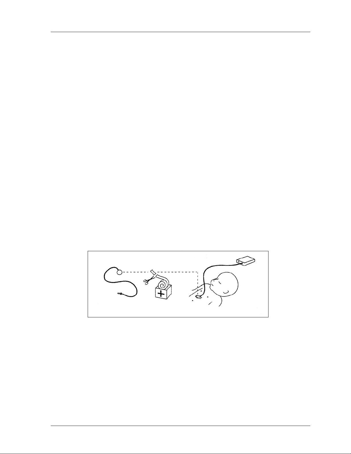
4 Connect the patient circuit and Infant Flow Generator as shown in Figure 2.
777077-101 Revision B June 2004
Page 23

Operator’s Manual 23
It is a Department of Health recommendation than an Oxygen Analyzer be used
at ALL TIMES when Oxygen Enriched Gases are being administered.
Figure 2 - Set Up Infant Flow Advance System
This figure is a general indication of how the various devices would be
interconnected in a typical setup. The actual configuration will vary dependent on the
type of ancillary equipment used.
WARNING
Liquid water or other contaminants in either gas supply, particularly the air
supply, will cause malfunction of this equipment and equipment connected to
it.
5 Set the desired delivery temperature on the heated humidifier and switch it on.
777077-101 Revision B June 2004
Page 24

24 Infant Flow Advance™ System
NOTE
We recommend that the temperature be set between 36 °C (96.8 °F) and 37 °C
(98.6 °F) but never higher than 37 °C (98.6 °F) for inspired gases.
6 Select the appropriate sized bonnet. Full instructions on placement of the
bonnet and fixation may be found on the instruction leaflet included with the
bonnets and generator.
• Use the forehead and the nape of the neck as reference points when
measuring the infant’s head to determine the proper bonnet size.
• Too small a bonnet may cause it to ride up, putting tension on the patient
interface, distorting the infant’s nose.
• Too large a bonnet may allow it to slide down over the infant’s eyes and
release the interface from the infant’s nose.
7 Open a Generator set and attach it to the circuit. Select the largest size
interface that will fit the infant’s nares (for prongs) or around the nose (for
masks). When fitted correctly, nasal prongs should be inside the nares with
some space existing between the prong and the nose. The generator
assembly should not be pulling up on or causing distortion to the infant’s nose.
8 Attach the prongs or mask interface to the Generator.
9 Switch on the Infant Flow Advance™ using the on/off switch at the rear of the
Infant Flow™ driver.
- The Breath and Apnea alarm indicator lamps are illuminated briefly when
the equipment is first powered. If either lamp is not working, do not use
the equipment.
- All the elements of the display are exercised at switch-on so that the
operation of the display can be checked, and the software version can be
viewed.
- The display presents the Pre-treatment Set-up screen after two seconds
(see Appendix for typical screen displays).
10 Occlude the patient interface.
11 Turn the gas flow to 8 L/min using the knob under the flow meter and verify
that the pressure reads 5 cmH
leaks if 5 cmH
O is not achieved. The flow meter indicator may take up to 3
2
seconds to settle after a step change in flow has occurred.
12 Once the CPAP pressure is set, the button under the CPAP icon should be
pressed. The flashing ‘?’ will change to a '9’
13 Set the required FiO
using the O2% graduated control.
2
14 Set the Pressure Assist characteristics by:
O. Check breathing circuit and connections for
2
• Adjusting the flow by using the knob above the transducer connection to the
right of LED display. Check the additional pressure on the graphic display.
• Once set to the desired level, the button under the PA icon should be pressed
and the flashing ‘?’ will change to a ‘9’.
777077-101 Revision B June 2004
Page 25

Operator’s Manual 25
15 The button under the patient icon should be pressed when the Interface and
sensor have been properly attached or when the user has decided that this
option is not required. The flashing ‘?’ will change to a ‘9’.
CAUTION
The 5 mark indicates the connection between the Transducer Interface and the
Driver only. It does not indicate correct positioning of the abdominal respiratory
sensor.
16 Fit the generator to the patient and bonnet. Ensure that the correct size
interface is selected and that the entire assembly is properly fitted to the infant.
Use the largest size interface that fits the infant’s nares or around the infant’s
nose to form a seal.
17 When properly set, the prongs should be inside the nares. There should be
some space between the prong set and the infant’s nose. The prongs should
not be pulling up on the infant’s nose. Alternatively, the mask should be snugly
fitted around the nose. The mask should not press down on the infant’s face
or come into contact with the infant’s eyes or mouth. Refer to the instruction
insert found with the bonnet or generator packaging for a diagram of final
fixation position.
18 Small adjustments to the nasal CPAP flow rate may be required until the
display reads the prescribed CPAP level. The relationship between the flow
setting and CPAP pressure should be compared with Figure 1 as a reference.
If outside the suggested range, check with the troubleshooting section of the
manual.
19 If Apnea monitoring or trPA is required, attach the abdominal respiratory
sensor to the patient and to the Transducer Interface, and the Transducer
Interface to the Infant Flow Advance Driver. Refer to Appendix C for
placement instructions. At this point a ; will appear on the screen to identify
the Transducer Interface is connected and remain on the screen until the
Transducer Interface is disconnected.
WARNING
The abdominal respiratory sensor is used only to enable features associated
with the Pressure Assist (PA) and Triggered PA (trPA) modes on the Advance
driver. When using the abdominal respiratory sensor, always use an
additional, external device for monitoring of the respiratory rate and detection
of apneic episodes as well as an appropriate monitor for continuous SaO2
monitoring.
CAUTION
The 5 mark indicates the connection between the Transducer Interface and the
Driver only. It does not indicate correct positioning of the abdominal respiratory
sensor.
777077-101 Revision B June 2004
Page 26

26 Infant Flow Advance™ System
NOTE
The LED on the Transducer Interface and the Infant Flow Advance™ will flash
simultaneously when a patient breath is detected. If either LED does not illuminate
fit an alternative Transducer Interface, or contact your local VIASYS Healthcare
representative.
20 Using the Treatment Set-up screens;
• Set the duration of the Pressure Assist by adjusting Ti and Ti. The
default setting is 0.3 seconds.
• Set the rate in Pressure Assist mode by adjusting R and R. The default
is 30 per minute.
• In Triggered Pressure Assist, the rate is the back-up rate should the patient
become apneic. In this mode the default setting is 10 per minute.
• Set the Apnea alarm period by pressing the Alarm bell button. The alarm
period can be set at 10, 15, 20, 25 and 30 seconds. The default setting is 20
seconds.
NOTE
During set-up of any mode the user can return to the Treatment Selection screen by
selecting ‘
21 Set the pressure and FiO2 alarms by pressing and holding the Alarm Silence
’ key.
button for three seconds.
NOTE
The over and under pressure alarms are set and detect pressure over a period of
time. In the Pressure Assist modes, the mean pressure over the timed period will be
higher than just CPAP. The alarms should therefore be set around this average.
22 Ensure that the nasal CPAP pressure is that which is prescribed. The "Target
Range" section of the bar graph indicates the most commonly used pressures
with the Infant Flow Generator. However, the actual pressures used for the
treatment of individual patients must be prescribed by the clinician.
Minor variations between devices occur but the pressure delivered should
always be within ± 10% of those shown on the Nomogram (Figure 1). If they
are out of specification check that there are no leaks in the patient circuit.
23 The electronic alarms for FiO
minute stabilization period. Should you wish to set them earlier, simply hold
the Arm/Mute button in for three seconds. The alarm will bleep to indicate that
and pressure will automatically set after a 2
2
777077-101 Revision B June 2004
Page 27

Operator’s Manual 27
your command has been accepted and the Alarms Armed indicator will
illuminate.
24 Should you change the nasal CPAP treatment pressure or the Oxygen
concentration, it is necessary to reset the alarm levels by holding the Arm/Mute
button in for three seconds.
25 In order to change treatments at anytime, first unlock the screen by pressing
the ‘key strike-thru’
to end the current treatment and return to the treatment selection screen.
CPAP will always be applied.
26 A single Pressure Assist may be delivered at any time. This can be applied to
the patient by first unlocking the screen by pressing the ‘key strike-thru’
button, and then pressing the
button. Then, press the ‘treatment strike-thru’ button
button.
NOTE
The duration of the single Pressure Assist will be the default value of Ti unless
changed through the PA Set-Up screen.
NOTE
The ball in the Flow meter will ‘bounce’ during operation in the PA and trPA modes.
This is a normal occurrence during these modes. For pressure reading see the LED
display.
27 Should Apnea monitoring be required, the Transducer Interface must first be
attached to the Infant Flow Advance Driver, then an Abdominal Respiratory
Sensor should be attached to the patient and the Transducer Interface. The
apnea monitoring period may be adjusted between 10 and 30 seconds in 5
second interval by pressing the button beneath the bell symbol.
WARNING
The abdominal respiratory sensor is used only to enable features associated
with the Pressure Assist (PA) and Triggered PA (trPA) modes on the Advance
driver. When using the abdominal respiratory sensor, always use an
additional, external device for monitoring of the respiratory rate and detection
of apneic episodes as well as an appropriate monitor for continuous SaO2
monitoring.
28 What to do if an alarm occurs - Always attend alarm conditions immediately as
the patient may not be receiving the prescribed FiO
have become apneic. Check all connections between the device and the
patient.
29 There are two distinct alarm types built in the Infant Flow Advance. The
Air/Oxygen Mixer has a mechanical bypass and alarm system which will sound
if one of the supply gases is below or above the range of pressure which can
be handled satisfactorily.
30 The second alarm system consists of an electronic system built into the
pressure and Oxygen monitoring module. This has several functions as shown
in Table 1 in this chapter. All electronic alarms with the exception of the
or nasal CPAP or may
2
777077-101 Revision B June 2004
Page 28

28 Infant Flow Advance™ System
overpressure alarm are self re-setting. In the event of an overpressure being
detected (> 11 cmH
which removes gas flow from the patient circuit.
O), the Driver activates a vent-to-ambient solenoid valve
2
WARNING
Nasal CPAP treatment in general can cause nasal irritation, septal distortion,
skin irritation and pressure necrosis. Adherence to the recommended usage
instructions for the Infant Flow Advance accessories may reduce the incidence
of these complications.
31 Nasal CPAP is not a benign procedure, all operators must be aware of the
possible hazards and complications associated with this treatment. Operators
must apply all necessary precautions to ensure safe and effective application
and treatment.
32 Do not over-tighten the generator straps. There is a risk of tissue damage.
33 Always choose the correct interface size.
34 Check the infant at least every 3-4 hours for the following:
• nasal irritation and septal distortion;
• skin irritation and pressure necrosis;
• nasal mucosal damage due to lack of humidification;
• gastric insufflation;
• abdominal distention.
777077-101 Revision B June 2004
Page 29

Operator’s Manual 29
TABLE 1 - Infant Flow Advance Driver Alarm Systems
Alarm function Device Action Operator Action
Oxygen supply failure Audible alarm. Check and restore oxygen
supply.
Air supply failure Audible alarm. Check and restore air supply.
High oxygen
concentration
Low oxygen
concentration
High pressure Audible alarm & high pressure
Low pressure Audible alarm & low pressure
Apnea timeout period Audible alarm & LED illuminated Check patient to determine
Audible alarm & high oxygen
indicator illuminated.
Audible alarm & low oxygen indicator
illuminated.
indicator illuminated.
indicator illuminated.
Check supply gases and/or
galvanic fuel cell. Press the
Arm/Mute button to silence the
audible alarm.
Check supply gases and/or the
galvanic fuel cell. Press the
Arm/Mute button to silence the
audible alarm.
Check the flow rate and check
for occluded tubes. Press the
Arm/Mute button to cancel the
alarm or restore pressure in the
circuit.
Check the flow rate and check
for occluded or disconnected
tubes or nasal interface. Press
the Arm/Mute button to silence
the audible alarm.
breathing. Check position of
abdominal respiratory sensor.
Check connections between
the sensor, the Transducer
Interface and the Driver.
Replace Transducer Interface
and sensor as appropriate.
The alarm will self cancel if the
cause is removed within the
first timeout period. If it is not
removed, then the Arm/Mute
button must be pressed to
silence the audible alarm.
777077-101 Revision B June 2004
Page 30

30 Infant Flow Advance™ System
TABLE 2 – Default Settings and Set Ranges
DEFAULT SETTINGS
Inspiration Time Ti: 0.3 seconds (+/- 1%)
Breath rate - detected Breaths Per Minute bpm +/- 1
PA Rate (During Pressure Assist) R: 30 / minute
Back Up Rate (During Triggered Pressure Assist) Rb: 10 / minute
Apnea Alarm Delay 20 seconds (+/- 1%)
SET RANGES
Inspiration Time Ti: 0.1s to 1.0s
PA Rate (During Pressure Assist) R: 1 – 120 / minute
Back Up Rate (During Triggered Pressure Assist) Rb: 1 – 30 / minute
Apnea Alarm Delay 10, 15, 20, 25, 30 seconds
Variable Additional Flow 0 – 5 L/min
777077-101 Revision B June 2004
Page 31

Operator’s Manual 31
Chapter 5: Clinical References
1 Klausner J, Lee AY, Hutchison AA. Decreased imposed work with a new nasal
continuous positive airway pressure device. Pediatr Pulmonology 22:188-194,
1996.
2 Moa G, Nilsson K, Zetterstrom H, Jonsson LO. A new device for administration
of nasal continuous positive airway pressure in the newborn: an experimental
study. Crit Care Med 16:1238-1242, 1988.
3 Rasanen J, Leijala M. Breathing circuit respiratory work in infants recovering
from respiratory failure. Crit Care Med 19:31-35, 1991.
4 Guilleminault C, et al. Upper airway resistance in infants at risk for sudden
infant death syndrome. J Pediatr, Volume 122, Number 6, June 1993.
5 Moa G, Nilsson K. Nasal continuous positive airway pressure: experience with
a new technical approach. Acta Pediatr 82: 210-11, 1993
6 Avery ME, et al. Is chronic lung disease in low birth weight infants preventable?
A survey of eight centers. Pediatrics 79:26-30 1987.
7 Higgins RD, Richter SE, Davis JM. Nasal continuous positive airway pressure
facilitates extubation of very low birth weight neonates. Pediatrics 88:9991003, 1991.
8 Locke RG, et al. Inadvertent Administration of Positive End-Distending
Pressure During Nasal Cannula Flow. Pediatrics (ISSN 0031 4005) 1993.
9 Stocks J. Effect of nasogastric tubes on nasal resistance during infancy.
Archives of Diseases in Childhood, 55:17-21, 1980.
10 Courtney, SE, et al. Lung volume changes during nasal continuous positive
airway pressure (nasal CPAP) in preterm infants: comparison of a variable vs a
continuous flow device. The American Pediatric Society and The Society for
Pediatric Research Abstract, #989, May 1998.
777077-101 Revision B June 2004
Page 32

32 Infant Flow Advance™ System
777077-101 Revision B June 2004
Page 33

Operator’s Manual 33
Chapter 6: Routine Maintenance
WARNING
Disconnect power supply before servicing.
Routine maintenance of the Infant Flow Advance is limited to regular checking of the
oxygen analyzer calibration and periodic (every 4 months) checking of the
Air/Oxygen Mixer and Electronic Pressure Manometer, status of the gas inlet filters,
integrity of the alarm system and cleaning of exterior surfaces.
An Infant Flow Advance in need of recalibration, service or repair must not be used
until the necessary procedures are performed and the equipment has been tested to
ascertain that it is functioning correctly.
Ensure pole clamp screws and clamp are securely fastened.
The Infant Flow Advance Service Manual is available to qualified technicians to
effect calibration, service and repair. If this is not feasible, contact VIASYS
Healthcare to insure full reliability and safety as special tools and equipment are
required.
Service and/or repair of this instrument is restricted to VIASYS Healthcare
authorized or VIASYS Healthcare Trained Personnel only. Parts designated in
this manual should be replaced only with parts manufactured or sold by VIASYS
Healthcare.
Gas Inlet Filters – The exterior air filter can be observed through the polycarbonate
bowl. If it is discolored or wet it should be replaced.
CAUTION
The precision gas blender incorporated in this product may become non-functional or
damaged if used without the protective water trap and filters provided.
Oxygen Analyzer Calibration
The integral oxygen analyzer is of the fuel cell type and as such requires regular
calibration. To perform this check, set up the Infant Flow Driver as for use and allow
2 minutes for stabilization of the electronic measuring circuits.
Select an oxygen concentration of 21%, wait 2 minutes and verify that the display
indicates 21. If not, remove the small white plug adjacent to the 21% mark on the
side of the device and adjust the potentiometer to give a reading of 21.
Set the mixer to 100%, wait 2 minutes and verify that the display indicates 100. If not,
remove the small white plug adjacent to the 100% mark on the side of the device and
adjust the potentiometer to give a reading of 100.
Return the mixer to the 21% position and verify that the display reads 21. There may
be some small interaction between the set point controls if a gross adjustment is
required and the process may need to be repeated two or three times. If this is the
case, it is indicative that the fuel cell is wearing out and should be replaced. Refer
777077-101 Revision B June 2004
Page 34

34 Infant Flow Advance™ System
the Infant Flow Advance Driver to a competent service department for replacement
of the fuel cell. Once calibration is completed, please replace the white plugs.
Cleaning
The exterior surfaces of the Infant Flow Advance Driver and Transducer Interface
can be cleaned with a mild soap or liquid disinfectant solution. Do not use cleaning
agents that contain abrasives. Care should be taken to ensure that cleaning
solutions do not enter the unit via any patient connection ports.
CAUTION
Do not immerse any part of this device or gas or steam sterilize it. Damage will
result.
Single Use devices should be disposed of in accordance with local regulations for
bio-hazardous materials after use.
Battery Maintenance
The Infant Flow Advance™ incorporates a sealed lead acid battery. There is no
routine maintenance to be carried out on this battery which has an expected useful
life of five years. The Infant Flow Advance™ has a built in charger which will safely
charge the battery and keep it in the best possible condition. It is recommended that
the driver is connected to an external power source via the approved AC adaptor
whenever possible to ensure that the battery is fully charged should it be required for
transport or in the event of a power failure.
NOTE
Due to local regulations these options are not available in all markets.
WARNING
The Infant Flow Advance™ must only be operated with the supplied approved
AC adaptor (refer to appendix B for a list of approved accessories).
777077-101 Revision B June 2004
Page 35

Operator’s Manual 35
NOTE
All of the functional accessories supplied by VIASYS Healthcare for use with the
Infant Flow™ driver are for single patient use only. These accessories include the
Infant Flow™ generator, delivery breathing circuits, humidification chambers,
silencer/bacteria filters and fixation bonnets. Under no circumstances should
sterilization or re-use of these products be attempted.
Exhausted batteries and oxygen fuel cells both contain lead and must be disposed of
according to local regulations.
777077-101 Revision B June 2004
Page 36

36 Infant Flow Advance™ System
777077-101 Revision B June 2004
Page 37

Operator’s Manual 37
Chapter 7: Summary of Symbols
The following international standard symbols may appear on the Infant Flow
Advance and in this manual. It is essential that all users of the equipment have a firm
understanding of the symbols.
EN60601 Type B Patient
Applied Part.
AC Alternating Current
DC Direct Current
Internal Battery Fully Charged
Internal Battery Low
Year of Manufacture
Fuse
Activate / Reset Alarm
Silence Alarm
Patient Circuit Connections
Respiratory Sensor
Connections
High Alarm
Read the Accompanying
Documents
Electric Shock Hazard
Unique Batch Number
Identifier
Use Before Expiry Date
Shown
Year-Month
Single Use Only
Do NOT Re-use
External Power Source
Connected
777077-101 Revision B June 2004
Page 38

38 Infant Flow Advance™ System
Low Alarm
Keep Away From Heat
Power on
Power Off
Application of a single
Pressure Assist cycle.
EN60601 Type BF Patient
Applied Part.
Keep Dry
CE Mark and Notified Body
Number.
Please read the Operator’s
Manual.
ETL mark and registration
number.
777077-101 Revision B June 2004
Page 39

Operator’s Manual 39
Appendix A: Screen Flow Diagrams
Figure 3 – Setup Scenario I
In this scenario, the Transducer Interface is not present and therefore not all modes
are available.
777077-101 Revision B June 2004
Page 40

40 Infant Flow Advance™ System
Figure 4 - Setup Scenario II
Patient Abdominal Respiratory Sensor is present and the Transducer Interface is
connected; all modes are available. If the Transducer Interface is disconnected, the
device reverts to the treatment selection screen (see Figure 3) unless non-triggered
PA therapy is being delivered (in which case it switches to un-monitored PA).
777077-101 Revision B June 2004
Page 41

Operator’s Manual 41
Appendix B: Approved Accessories
VIASYS P/N EME P/N Ref. Description
Infant Flow Advance Generators
777085-102 D350T Infant Flow nasal CPAP Generator (Box of 20)
777085-101 D350T/10 Infant Flow nasal CPAP Generator (Box of 10)
Infant Flow Advance Bonnets
777084-101 DBWH000 Infant Flow Bonnet – Size 000 (White)
777084-102 DBGY00 Infant Flow Bonnet – Size 00 (Grey)
777084-103 DBPK0 Infant Flow Bonnet – Size 0 (Pink)
777084-104 DBBR1 Infant Flow Bonnet – Size 1 (Light Brown)
777084-105 DBYE2 Infant Flow Bonnet – Size 2 (Yellow)
777084-106 DBBL3 Infant Flow Bonnet – Size 3 (Light Blue)
777084-107 DBGO4 Infant Flow Bonnet – Size 4 (Gold)
777084-108 DBGR5 Infant Flow Bonnet – Size 5 (Green)
777084-109 DBBU6 Infant Flow Bonnet – Size 6 (Light Burgundy)
777084-110 DBOR7 Infant Flow Bonnet – Size 7 (Orange)
777084-111 DBDG8 Infant Flow Bonnet – Size 8 (Dark Green)
777084-112 DBNA9 Infant Flow Bonnet – Size 9 (Navy)
Infant Flow Advance Mask/Prong Patient Interfaces
777086-101 D360XS Nasal Mask Extra Small
777086-102 D360XL Nasal Mask Extra Large
777086-103 N/A Nasal Mask Extra-Extra Large
777087-101 D360S Nasal Prong Small
777087-102 D360M Nasal Prong Medium
777087-103 D360L Nasal Prong Large
Infant Flow Advance Standard Circuits
773386 C8112E Patient Circuit IF, F&P 730 (Box 20)
773387 N/A Patient Circuit IF, F&P 850 (Box 20)
773388 N/A Patient Circuit IF, RCI 380-90 16V (Box 20)
773389 N/A Patient Circuit IF, RCI 380-88/Concha IV 21V (Box
20)
Infant Flow Advance Miscellaneous Parts and Accessories
D1420/100 Same Infant Flow Silencer/Bacteria Filter (Box 20)
M674-920 Same Infant Flow Advance Service Manual (English)
673-055-A M673055A Infant Flow Pole and Stand complete with IV
extension pole
772-235-A M772235A Infant Flow Pole and Stand without IV extension pole
772236 M772236 Infant Flow extension pole alone
674-037 MW160MA
777223 N/A AC Adapter Australia and New Zealand, M674A only
M674ARC same Abdominal Respiratory Sensor (Box 25)
M677-1 same Infant Flow Advance Transducer Interface
AC Adaptor (MW160)
Note
A complete list of service parts can be found in the Service Manual.
777077-101 Revision B June 2004
Page 42

42 Infant Flow Advance™ System
777077-101 Revision B June 2004
Page 43
Operator’s Manual 43
Appendix C: Abdominal Respiratory
Sensor Placement
1. Connect the Abdominal Respiratory Sensor (A.R.S.) to the Infant Flow
Advance
2. Switch on the Infant Flow Advance (refer to Chapter 4, Operating Instructions).
Light compression of the respiratory sensor causes the LED on the transducer
interface to illuminate, indicating that the sensor and transducer interface are
functioning.
3. Site the A.R.S., taking the following into account:
• Ensure that the abdomen exhibits consistent outward movement during each
spontaneous inspiratory effort.
• Place the sensor in a position where no retractions are present. Avoid areas
just below the rib margin and in proximity to an active pericardium.
• Ensure that the patient does not lie on the A.R.S. Considering periodic body
position changes, a lateral abdominal site may be preferred for this reason.
4. Select a fixation tape that is suitable for the patient.
5. Place the A.R.S. in the center of the tape with the pressure line perpendicular
to the tape.
6. Place the A.R.S. between the umbilicus and the xiphisternum (refer to
Figure 5).
TM
transducer interface.
Figure 5 - A.R.S. Placement
7. Stretch the tape as you apply the A.R.S. to the patient, providing a taught
profile.
8. Verify correct A.R.S. placement by observing spontaneous breathing. The
onset of inspiration for each spontaneous breath (abdomen moving outward)
must be accompanied by the LED flashing.
777077-101 Revision B June 2004
Page 44

44 Infant Flow Advance™ System
777077-101 Revision B June 2004
Page 45

Operator’s Manual 45
Glossary of Terms
CPAP Continuous Positive Airway Pressure
Nasal CPAP Nasal Continuous Positive Airway Pressure.
PA Pressure Assist – extra flow is delivered causing an increase in pressure
through the generator. This is in addition to current CPAP
trPA Triggered Pressure Assist gives the same effect as PA but only when the
baby’s inspiratory effort is detected
CDP Continuous Distending Pressure
FRC Functional Residual Capacity
L/min Liters per minute
cmH2O Centimeters water pressure
PSI Pounds per Square Inch
Bar A pressure of one atmosphere
Ti Period of time that the additional pressure is available to the patient during
Pressure Assist modes
R Rate - number of times the additional pressure will be applied during the PA
Rb Back-Up Rate - number of times the additional pressure will be applied
during detected periods of apnea in trPA
bpm Breaths Per Minute – as detected by the Abdominal Respiratory Sensor
I:E The ratio between the length of time that the additional pressure is available
to the patient (Ti) and the length of time that the CPAP pressure is available
to the patient
777077-101 Revision B June 2004
Page 46

46 Infant Flow Advance™ System
777077-101 Revision B June 2004
 Loading...