

Page 1
Emergency Pneumatics.
Operating InstructionS
VETTER Ultra Flat Bags S.Tec 10 bar
Article No. 9987054002 | © Vetter GmbH I 07/14 I Changes and errors excepted.
Page 2

Vetter Ultra Flat Bags S.Tec 10 bar
Contents
1. Important preliminary remarks ....................................2
2. Description of the set .............................................2
2.1 Other accessories ...........................................4
2.2 Vetter safety coupling system ...............................5
2.3 Product description .........................................5
2.4 Correct usage ...............................................7
2.5 Safety instructions ..........................................7
3. Preparing the product for use .....................................9
3.1 Preparations for operation ..................................9
3.2 Application instructions .....................................9
4. Operating instructions ............................................9
4.1 Operation with compressed bottles .........................9
4.2 Operation with other sources of compressed air ........... 10
4.3 Dismantling of the lifting bag system after use .............11
4.4 Limit for the period of use ................................. 11
4.5 Care, maintenance and storage. . . . . . . . . . . . . . . . . . . . . . . . . . . . 11
5. Elimination of defects ........................................... 12
6. Repetitive tests .................................................12
7. Technical data ..................................................13
EC Conformity Declaration (available on request) ...................14
Page 1/15
Page 3
1. Important preliminary remarks
Only the knowledge and exact observance of these operating instructions guarantee correct and professional operation, produces
the greatest possible use and ensures any claims made within the
scope of the Vetter guarantee.
The handling of the Vetter Ultra Flat Bags S.Tec is only to be made
by trained persons using the operating instructions of the manufacturer and the information from the user. The disposal of discarded lifting bags is to be carried out according to disposal regulations valid for the region.
The operating instructions given here are to be regarded as part
of the product and are to be kept for the complete life duration of
the product. In case the product should be passed on to a successive user then the operating instructions must also be included.
2. Description of the set
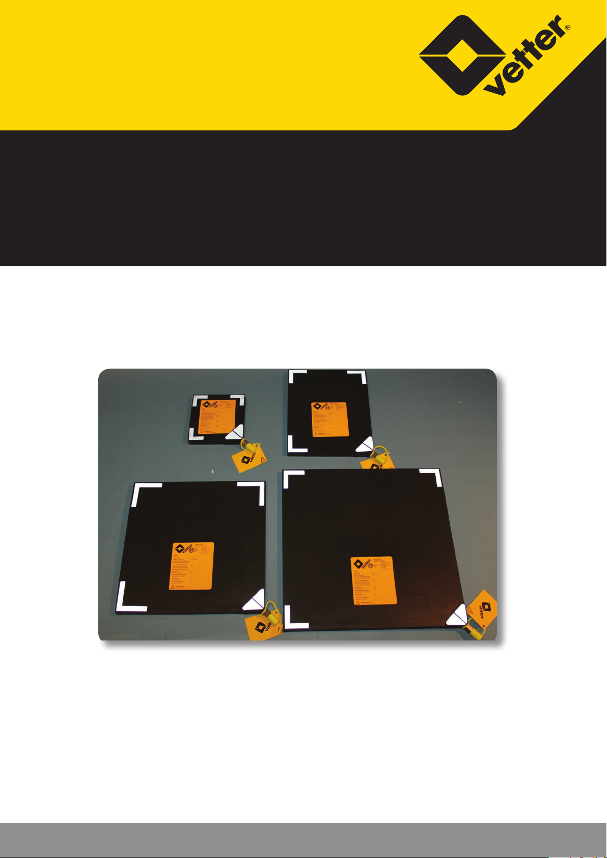
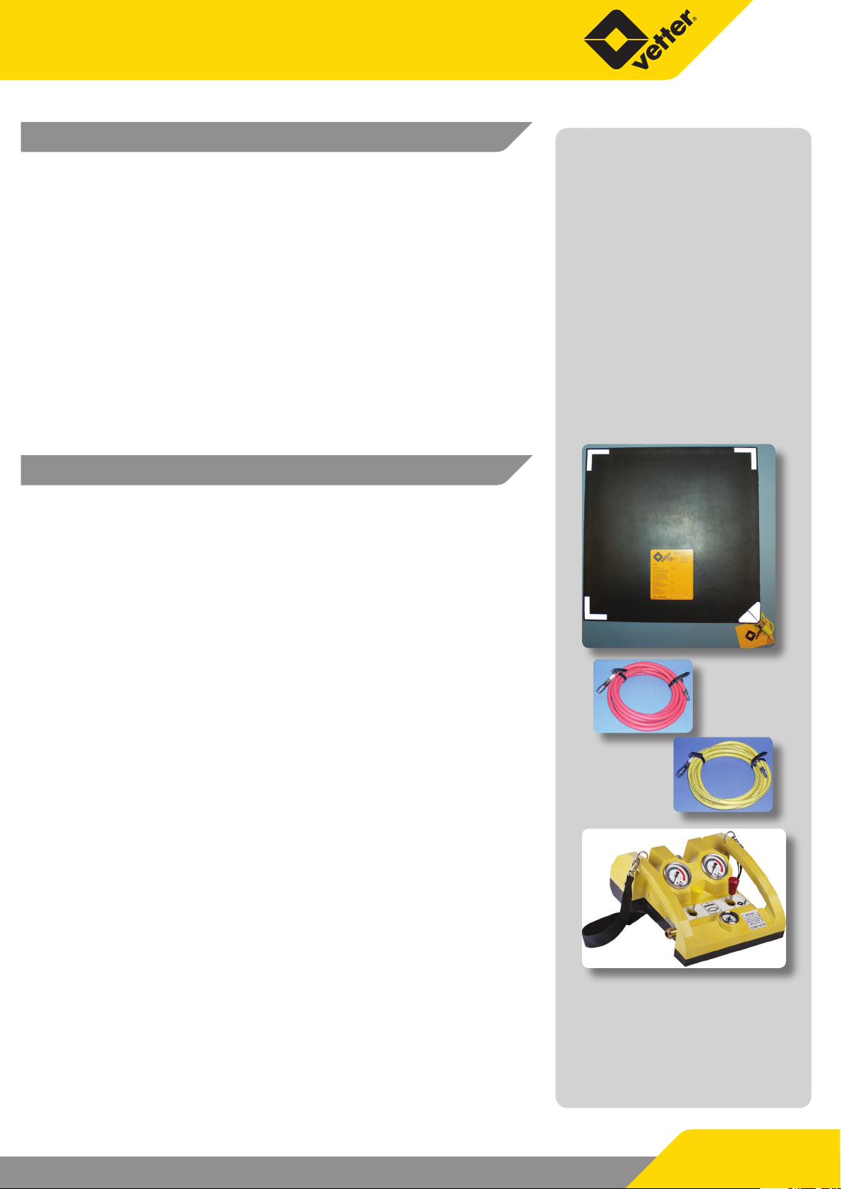
a. Ultra Flat Bags S.Tec 10 bar
The selection of bag size must correspond to operation requirements. There are 4 sizes available from 1.1 to 11.6 t.
b. Ination hoses
In order to inate Vetter Ultra Flat Bags S.Tec from a safe position
for the operator, there are ination hoses available with lengths
of 5 m and 10 m. The hose colours in RED and YELLOW are used
exclusively to assist the operator in recognizing the correct side
when controlling the Vetter Ultra Flat Bags S.Tec.
c. Air CU (Control Unit) 10 bar deadman
Connect the ination hoses on the output couplings on the rear
side of the controller. Connect the air suppply to the input coupling on the side. Move the switching lever to the front in order to
inate the Ultra Flat Bags S.Tec. In doing this, observe the corresponding manometer and the load.
When the required operating pressure for the lifting power or lift
height is reached, terminate the ination sequence by releasing
the lever. The switching lever automatically returns back to the
zero position (dead-man switching). The integrated safety valve
activates automatically as soon as the maximum operating pressure of 10 bar is exceeded when inating or when there is a sudden increase in bag pressure caused by an unintended loading of
the bag.
The activation tolerance for opening and closing of the
safety valve must only be a maximum of +/- 10%.
Press the switching lever in the opposite direction in order to deate the bag or to lower the load.
Page 2/15
Page 4
Vetter Ultra Flat Bags S.Tec 10 bar
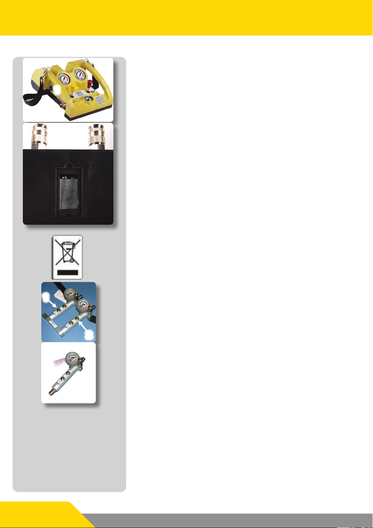
Additional information for illuminated control element
Air CU 10 bar Totmann lighting
1
Dierent couplings!
The lighting of the control element illuminates all couplings,
switch levers and manometers. It is switched on and o with
switch (1) on the side.
The control element is supplied by a 9 V block battery. Since the
entire lifting bag system is designed for a temperature range of
-20 °C to +55 °C, only batteries with this temperature range are
allowed to be used. Based on the current state of the art, only lithium batteries meet this requirement.
To insert the battery, unscrew the battery compartment, replace
the old battery with a new one and screw the battery compartment back together.
Control elements with lighting come under the German Law on
electrical and electronic devices (ElektroG) of 24 March 2005 for
implementation of the EC Directive 2002/96/EC on electrical and
electronic waste – WEEE Directive.
The label attached to the battery compartment cover points
out that the electronic components in this product must not be
handled as domestic waste; they have to be returned to the manufacturer (return freight paid) for recycling.
d. Dual controller 10 bar with dead-man switching,
1
2
aluminium
Press the lower button (1) in order to inate the bag. After release,
the press-button returns again to the zero position and interrupts
the ination sequence. Press the upper button (2) in order to deate.
e. Single controller 10 bar with dead-man switching,
aluminium
If only one Ultra Flat Bag S.Tec is used for operation then this can
be controlled with a single controller.
Inventory check
On acceptance of the Ultra Flat Bags S.Tec equipment a check is to
be made to see if the delivery is complete according to the delivery note. In addition to this a visual check and function test is to be
made according to the operating instructions.
Page 3/15
Page 5
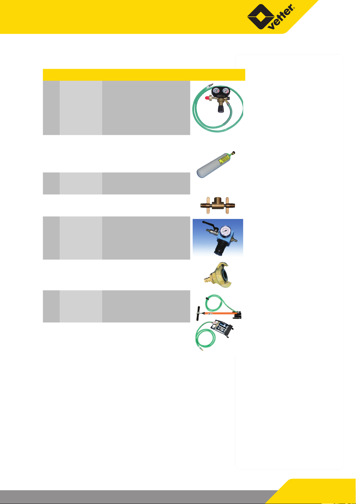
2.1 Other accessories
Pos. Article No. Description
1
or 1600 0262 00
2
3
4
5
1600 0261 00
1600 0108 00
1600 0199 00
1600 0091 00
1600 0145 00
Pressure regulator 200/300 bar
US Version 4500 psi
(not compatible with below
mentioned compressed air
bottles)
Comp. air bottle
6 l / 300 bar
Comp. air bottle 9 l / 300 bar
Dual connector
300 bar
Pressure regulator
6
7
8
1600 0120 00
1600 0087 00 Hand pump (7)
1600 0094 00 Foot pump (8)
Adapter for construction site
compressor
7
8
Page 4/15
Page 6

Vetter Ultra Flat Bags S.Tec 10 bar
2.2 Vetter safety coupling system
3
2
1
a. Input coupling of the controller
Connect the air supply hose or the connection hose of the pressure regulator to the nipple of the input coupling (1) on the controller pushing the nipple solidly into the coupling until the ratchet
action can be felt. In order to ensure that it is correctly connected:
turn the brass sleeve (2) of the coupling opposite to the safety
pin (3).
b. Ination hoses
To connect the ination hoses to the corresponding controller or
to the Ultra Flat Bags S.Tec, press the hoses or bag nipple solidly
into the coupling until the ratchet action can be felt. The coupling
sleeve must be seated on the support ring without any gap (1). To
release the connection (only in the pressure-free condition) the
nipple must be solidly pressed against the spring pressure in the
1
coupling. At the same time the coupling sleeve must be pushed
back. The coupling then releases.
c. Ination with an 8 bar ination device
The Ultra Flat Bags S.Tec safety coupling system cannot be used
for ination with other ination devices. However, should it be
necessary, in exceptional cases, to inate with the Vetter 8 bar system then the 10 bar / 8 bar adapter must be used.
2.3 Product description
Vetter Ultra Flat Bags S.Tec are made by hand from high quality
raw materials so that after completion, a seamless bag is produced. The semi-nished product is vulcanized under the inuence
of pressure and temperature and by doing this the individual layers bond to form an elastomer body. After production has been
nalized, each Ultra Flat Bag S.Tec is subjected to a plant acceptance test within the scope of quality assurance.
Material of the Ultra Flat Bags S.Tec : CR/Aramide, hot vulcanized
Page 5/15
Page 7

Temperature resistance of Ultra Flat Bags S.Tec :
Cold resistance -40 °C
Cold exible -20 °C
Heat resistance long-term +90 °C
Heat resistance short-term +115 °C
The aramide layer on the Ultra Flat Bags S.Tec
can be damaged by damage made to the
bag surface, e.g. cuts, cracks, punctures or
by the eects of ozone.
Therefore with a visual check after every operation, special attention is to be made to the following types of damage:
9 Damage by separation
9 Damage by cuts
9 Damage by punctures
9 Damage by heat and chemicals
Danger of bursting! If, when carrying out the
check, this type of damage is determined
then the bag is to be immediately taken
out of service. Repair is not possible.
In order to use the maximum lifting power, the total eective area,
i.e. the total area minus the edge area, must be completely under
the load to be lifted and that the bag must be taken to the maximum permitted operating pressure.
The bag develops a spherical shape (with rectangular or square
base) as the lift height increases. This is the reason why the contact area with the load decreases until at a max. bag curvature
this will be almost zero. The largest lift height of the Ultra Flat Bag
S.Tec will only be reached in the unloaded state.
In case the lifting power produced by the Ultra Flat Bag S.Tec is
not sucient, depending on the lift height, then a number of
S.Tec Bags can be placed next to each other.
Page 6/15
Page 8

Vetter Ultra Flat Bags S.Tec 10 bar
In case the lifting height of an Ultra Flat Bag S.Tec is not sucient
then a maximum of 2 bags can be placed over each other. In this
mode, the lifting height is additive for both Ultra Flat Bags S.Tec.
However the lifting power only corresponds to that of the smaller
bag. Basically, the lower bag should always be inated rst.
Sequence: large bag below,
small bag on top!
Never place 3 or more bags over each other!
An Ultra Flat Bag S.Tec under load can be compared to a spring
under tension with respect to its behavour. As soon as the Ultra
Flat Bag S.Tec is suddenly released, e.g. by slipping, load break or
anything similar then there will be spontaneous catapulting outwards of the Ultra Flat Bag S.Tec.
Never stand in front of the Ultra Flat Bag S.Tec!
This is an area of danger!
2.4 Correct usage
First and formost, Ultra Flat Bags S.Tec are pneumatic rescue devices for rescue services (re services) in which trapped persons
can be freed and access can be obtained for rescue and carrying
our counter-measures as well as other similar measures. In addition to this Ultra Flat Bags S.Tec can be used as working equipment
for lifting or movement of loads. Ultra Flat Bags S.Tec 10 bar are
subject to national requirements of the re service sector. Further
instruction information can be obtained from the operating instructions of the user. The complete Ultra Flat Bag S.Tec system is
cold-resistant to -20 °C and heat-resistant up to +55 °C.
2.5 Safety instructions
Pre-specied personal protective clothing is to be worn during
operation! For example: protective clothing, helmet, protective
gloves, protection for eyes and face, noise protection etc.
The national regulations in connection with lifting bag systems
and their use are to be observed. For example: DIN EN 13731, national regulations. The Ultra Flat Bags S.Tec are only to be used
with compressed air, under no circumstances are they to be used
with inammable gases or aggressively acting gases. Vetter Ultra
Flat Bags S.Tec are only to be inated with original Vetter ination
ttings because these were subjected to an acceptance test by
the manufacturer. The lifting bag system is to be tested for perfect
condition before and after use (specications from the manufacturer, national regulations).
Page 7/15
The lifted load is to be continually supported during the progessive lifting sequence. The stable condition of foundation support
material must always be observed during construction of the
foundation support.
Page 9

Never position 3 or more bags on top of each
other!
Ensure load against slippage.
In order to fully use the strengths of the Ultra Flat Bag S.Tec, the
distance between load and bag should be at a minimum.
The foundation support must brace at
least the complete area of the bag and the
smallest edge length of the foundation
support must be larger than the height of
the foundation support. Metal must
never be place on metal!
Attention: danger of slipping!
With slippery ground (ice, snow, mud etc.) place anti-slip materials
under the bag in order to increase adhesion. Point-shaped loads
are to be avoided, e.g. construction claws or screws. Never place
the bags on sharp edges, hot or red hot components. Use suitable
temporary storages and cover the complete contact area of the
bag. Protect the bag against ying sparks during welding or separation work. Do not additionally load bags with such things as
hydraulic lifting devices, winches or falling loads.
Never remain beneath a lifted load, never hold
the load from below!
Remain at a distance!
Avoid shearing eects by squeezing of the bag when lowering the
load!
During operation never stand in front of
the bag but always to one side, because the
bag could catapult outwards under
unfavourable conditions!
The lifting sequence is to be stopped
immediately if there is a function failure!
An Ultra Flat Bag S.Tec can burst under adverse conditions with
incorrect operation, incorrect handling or by manipulation on the
controller and/or ination hose (problems concerning pressure
waves and sound waves, uncontrolled movement)!
Vetter Ultra Flat Bags S.Tec are not suited for
use in explosion endangered zones!
Special versions are possible on request!
Page 8/15
Page 10

Vetter Ultra Flat Bags S.Tec 10 bar
3. Preparing the product for use
3.1 Preparations for operation
Remove the Ultra Flat Bag S.Tec from the vehicle. Prepare the ination device. Ensure that sucient air supply is available.
Only perfectly working and tested Ultra Flat
Bags S.Tec systems are to be used!
From case to case, the head of operations is to decide, within his
area of responsibility, about the method to be used for the operation as well as the operating instructions of the user.
3.2 Application instructions
Insert the Ultra Flat Bag S.Tec at a suitable position so that at least
75% of the support surface of the bag is under the load. Continually built up the under-support for maintaining contact when the
load is lifted during the lifting procedure.
Never stand in front of the bag during operation but to the side of
the Ultra Flat Bag S.Tec because it could be catapulted outwards
under unfavourable conditions.
4. Operating instructions
4.1 Operation with compressed bottles
Connect the pressure reducer to the compressed air bottle
4
3
1
9
8
6
2
5
200 bar or 300 bar using the tommy screw (1). Close the hand
wheel of the pressure reducer (2). Open the valve on the
bottle (3). The pre-pressure manometer (4) indicates the pressure
in the bottle.
Adjust the back pressure to approximately 10/12 bar with the regulation bar (5) (indication of the reduced pressure on the back
pressure manometer (6)).
Connect the air hose of the pressure reducer via the nipple to the
input coupling (7) of the controller. In doing this, press the nipple
into the coupling until you feel it lock in. For additional safety: turn
the brass sleeve (8) so that it is opposite the safety pin (9).
Page 9/15
Open the hand wheel (2) of the pressure reducer.
7
The lifting bag system is ready for operation.
Page 11

4.2 Operation with other sources of compressed air
Basically, every source of air available can be used for operation of
the Ultra Flat Bags S.Tec as long as the pressure does not exceed
12 bar and that the air is free of oil as far as possible. Amongst
others, the set of transition pieces (Art. No.: 1600 0125 01) with
the following adapters are available for operation with other air
sources:
8 9
3
456 7
2 1
1. Truck compressed air connection, dual brake system.
For tapping air out of the trailer coupling head.
2. Dummy coupling
Seals o the control line of the brake system
10
Remember! Ensure that the truck does not roll, use brake
blocks!
3. Truck tyre ination device adapter
For tapping o air from the so-called tyre ination bottle
near the brake.
Remember! The tyre ination connection must be ensured by a safety valve as a standard (blow-o pressure approximately 7.5 bar)!
4. Truck tyre valve
Ination with a normal hand or foot pump as well as other
air supplies for tyre ination.
5. Truck tyre valve connection, can be clamped
For extracting air for the spare tyre.
6. Adapter for the local air pressure network.
7. Adapter Construction-site compressor
8. Air supply hose, 10 m, green.
9. Air supply hose, 10 m, green, with blocking valve.
10. Case, red
Page 10/15
Page 12

Vetter Ultra Flat Bags S.Tec 10 bar
4.3 Dismantling of the lifting bag system
after use
Dismantling of the lifting bag system is carried out after ensuring
the lifted load and complete deation of the lifting bag system,
including dismantling of all accessory parts in the reverse order.
4.4 Limit for the period of use
Ultra Flat Bags S.Tec are subject to natural aging the same as any
other rubber products. The aging of the material is initially indicated by the loss of exibility which especially becomes aparent
with the appearance of so-called aging cracks. If these cracks propagate in the cover material so that the ARAMIDE reinforcement
is no longer protected by the cover layer then this can lead to a
crack networks forming on the surface and thus cause bursting
of the bag.
The experiences gained in the last decade have clearly shown
that the general failure rate with rubber products considerably
increases from a period exceeding 15 years. Therefore Ultra Flat
Bags S.Tec should be replaced after 15 years, 18 years is the maximum. The danger for rescue services when using aged Ultra Flat
Bags S.Tec should never be underestimated for welfare reasons. It
should be stressed that although there is currently no regulation
about the maximum time limit, the responsibility rests fairly and
squarely with the user and the inspector commissioned by him.
4.5 Care, maintenance and storage
The lifting bag equipment is to be cleaned after every operation.
Cleaning is normally made with warm water and a soap solution.
Cleaning must never be carried out with
chemicals and high-pressure hot water
devices.
Drying is to be made at normal room temperature.
A bag is to be immediately discarded if, during inspection, any
sign of damage is established (refer to Page 6). Repair is not possible. If needed, components such as manometers, safety valves
and piston valves can be exchanged. Hose couplings and nipples
can also be exchanged. After necessary repair, the equipment is
to be checked according to the repetitive tests. This special test is
also to be documented.
Page 11/15
DIN 7716 is to be observed for long-term storage.
The VETTER Guarantee is 36 months for Ultra Flat Bags S.Tec.
Page 13

5. Elimination of defects
If the safety valve blows too early because of foreign body penetration caught up inside then the blow-o valve is to be fully
opened on the head of safety valve by turning counter-clockwise
so that the compressed air can escape. If, due to this, the foreign
body is not removed then the upper part of the safety valve is to
be unscrewed when the safety valve is disassembled. To do this,
position the pipe wrench in the centre and unscrew by turning to
the left.
Carefully take out the valve ball and remove foreign body. Firmly
screw on the upper part of the valve again, assemble the safety
valve and check operation. The set pressure must not be changed.
If the seal or the seal plate on the safety
valve of the controller on the upper part
of the valve has been removed then correct
operation is no longer guaranteed.
The safety valve is to be exchanged!
6. Repetitive tests
Lifting bag systems are to be subjected to repetitive tests according to DIN EN 13731 and national regulations (e.g. GUV-G 9102).
9 Testing on acceptance
Testing for completeness by the person/people delegated by
the user.
Visual check and operation test by a trained person according to the operation manual.
9 Visual check and operation test after each application/use by
the user.
This test is to be documented.
9 At least once every year the lifting bag system is to be given a
visual check and operation test by a trained person according
DIN EN 13731 and national regulations.
This test is to be documented.
9 At least every 5 years or if there is any doubt about the safety
or reliability, the lifting bag system is to be given a pressure
test by the manufacturer or a trained person with further training of the manufacturer, according to DIN EN 13731 and national regulations.
The user is responsible for the correct and professional execution
of the repetitive tests!
Page 12/15
Page 14

Vetter Ultra Flat Bags S.Tec 10 bar
7. Technical data
Ultra Flat Bags S.Tec 10 bar
Unit
Art. No.
Lift power
Lift height
Insertion height*
Dimensions
Operating max.
pressure
Test pressure
Air requirement
at 10 bar/145 psi
Nominal capacity
Burst pressure,
min.
Weight ca.
to
US tons
cm
inch
cm
inch
cm
inch
bar
psi
bar
psi
l
cu.ft.
l
cu.ft.
bar
psi
kg
lbs
UF 1 S.Tec UF 4 S.Tec UF 7 S.Tec UF 12 S.Tec
1315006000 1315006100 1315006200 1315005900
1.1 3.8 7.0 11.6
1.2 4.2 7.7 12.8
7.5 12.0 16.5 20.3
3.0 4.7 6.5 8.0
1.6 1.6 1.6 1.6
0.6 0.6 0.6 0.6
14 x 13 25.5 x 20 29.5 x 29.5 37 x 37
5.5 x 5.1 10 x 7.9 11.6 x 11.6 14.6 x 14.6
10 10 10 10
145 145 145 145
16 16 16 16
232 232 232 232
3.85 24.75 48.4 92.95
0.1 0.9 1.7 3.3
0.35 2.25 4.40 8.45
0.01 0.08 0.16 0.30
40 40 40 40
580 580 580 580
0.4 1.0 1.7 2.4
0.88 2.20 3.75 5.29
* around valve + 6 mm (0.2 inch)
All rights reserved for technical changes within the scope of product improvement.
Page 13/15
Page 15

EC Conformity Declaration (available on request)
in accordance with Directive 2006/42/EC
Manufacturer name and address:
Vetter GmbH
A Unit of IDEX Corporation
Blatzheimer Str. 10 - 12
53909 Zülpich
We hereby declare, that the VETTER Ultra Flat Bags S.Tec (Aramid) 10 bar for
lifting and lowering of loads
Type: ______________
Serial-No.: ______________
Model: ______________
(refer to equipment label, to be entered by the customer)
meets the following relevant provisions:
Directive 2006/42/EC on Machinery
Applied harmonised standards, references to which have been published
in the Ocial Journal of the European Union:
DIN EN ISO 12100
EN 13731
Applied national standards and technical specications:
Authorised representative for the compilation of technical documents:
Vetter GmbH
A Unit of IDEX Corporation
Blatzheimer Str. 10 - 12
53909 Zülpich
This EC Conformity Declaration was issued:
Zülpich, 03.07.2014
(Place, Date, Signature)
Page 14/15
Page 16

Place your trust in emergency pneumatics!
We are the company who can help you, nd a solution to your problem!
Vetter GmbH
A Unit of IDEX Corporation
Sales
Blatzheimer Str. 10 - 12
D-53909 Zülpich
Germany
www.vetter.de
Tel.: +49 (0) 22 52 / 30 08-0
Fax: +49 (0) 22 52 / 30 08-590
Mail: vetter.rescue@idexcorp.com
Article No.9987054002 | © Vetter GmbH I 07/14 I Changes and errors excepted. I Made in Germany
 Loading...