

Vetter Struts and Accessories User Manual
Emergency Pneumatics.
AIRSHORE Original Operating Instructions
AIRSHORE Struts and Accessories
ART-Struts for Rescue AA-F
Keep for future use!
Article No. 9987019202 | © Vetter GmbH I 11/14 I Changes and errors excepted.

AIRSHORE Struts and Accessories for Rescue
Contents
1. Important Basic Information ......................................3
1.1 Symbols Used ..............................................3
1.2 Scope of Delivery ...........................................4
1.3 Product Description ........................................5
1.4 Technical Data ..............................................5
1.5 Optional Accessories ........................................6
1.6 Interfaces. . . . . . . . . . . . . . . . . . . . . . . . . . . . . . . . . . . . . . . . . . . . . . . . . . .9
1.7 Conditions of Guarantee ....................................9
2. Safety Instructions ................................................9
2.1 Intended Use . . . . . . . . . . . . . . . . . . . . . . . . . . . . . . . . . . . . . . . . . . . . . 10
2.2 Possible Dangers ......................................... 10
3. Preparation for Use .............................................10
3.1 Preparing the Work .......................................10
4. Operating Instructions .......................................... 11
4.1 Manual Operation of the ART Strut ........................ 11
4.2 Pneumatic Operation of the ART Strut .....................11
4.3 Dismantling .............................................. 12
5. Repair and Maintenance ........................................22
6. EC Declaration of Conformity ................................... 23
Page 2/24
1. Important Basic Information
1.1 Symbols Used
Read the operating instructions!
Attention!
Warning of injury to hands!
Warning of cutting injuries!
Warning of retraction!
Wear protective gloves!
Wear protective boots!
Wear protection for face, head and ears!
Wear protective clothing!
Page 3/24
AIRSHORE Struts and Accessories for Rescue
element
Überströmöffnungen
Sicherungsstift
OBEN
Verriegelung
Kolben/Vorsatz
-
element
T-Griff
Sicherungsstift
mit Raster
Sicherungsstift
T-Griff
Muffe
UNTEN
OBEN
1.2 Scope of Delivery
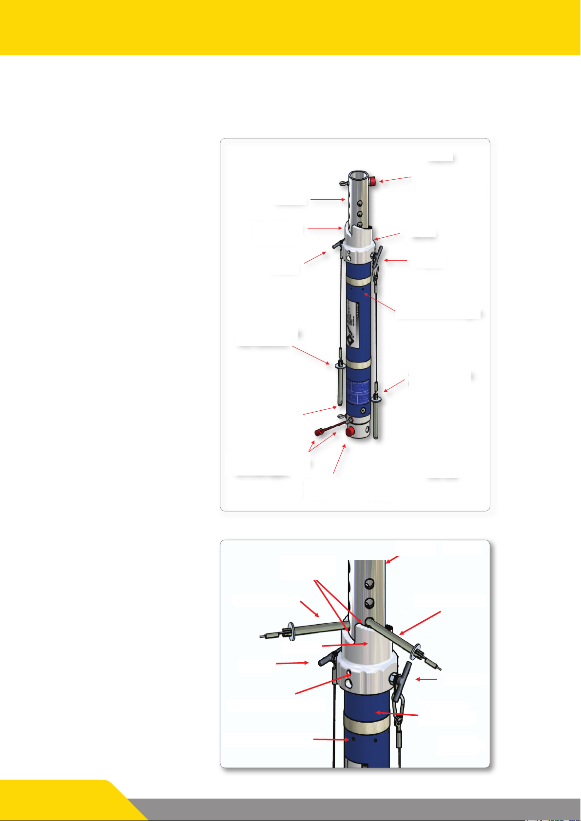
1.2.1 AIRSHORE ART Strut
Piston
Kolben
Wendelung
Spiral collar
mit Raster
with latch
T-grip
T-Griff
TOP
OBEN
Locking piston/
Verriegelung
Kolben/Vorsatz-
attachment
element
Sleeve
Muffe
T-grip
T-Griff
Safety pin
with holder
cable
mit Halteseil
Type plate
Air connection and
Luftanschluss und
Schutzkappe
protection cap
Verriegelung
Latch for support tube/
Stützenrohr/Fussplatte
base plate
1.2.2 Detailed View of ART Strut
Spiral collar
Wendelung
with latch
Overow openings
Safety pin
Sicherungsstift
with holder
mit Halteseil
cable
BOTTOM
UNTEN
Kolben
Piston
TOP
Page 4/24
Safety pin
Sleeve
T-grip
Bohrung in der Muffe
Sleeve drill holes
Overow openings
Überströmöffnungen
Safety pin
T-grip
Support
Stützenrohr
tube
BOTTOM

1.3 Product Description
The Airshore Rescue Tool is a light, form-t strut element made of aluminum 6061-T6, which is operated manually or pneumatically. The detachable attachments, angle pieces and base plates adjust to all shapes, surfaces
and situations. Airshore Rescue Tool was developed for stabilizing and
shoring in the vertical and/or horizontal line and in angled positions thus
enabling a safe base for your work in all situations.
The Airshore Rescue Tool is a reliable strut suitable for a number of combinations and congurations and provides due to the large number of
attachments, angle pieces and base plates.
1.4 Technical Data
1.4.1 Technical Data for ART-Struts
Airshore ART-Struts
Article Number Product Description Length in mm Weight in kg
7200 0130 01 ART-AA 330 - 450 4.1
7200 0013 02 ART-A 530 - 700 7.0
7200 0015 02 ART-B 660 - 940 8.0
7200 0018 02 ART-C 840 - 1250 9.0
7200 0095 01 ART-D 1150 - 1700 11.0
7200 0024 02 ART-E4.5-7 1370 - 2130 12.9
7200 0004 02 ART-F7-11 2130 - 3350 20.4
All rights reserved for technical changes within the scope of product improvement.
Strut Material:
All struts are made of high quality aluminum 6061-T6, fatigue-proof, galvanized steel and high-grade steel.
1.4.2 Technical Data for ART Extensions
Airshore ART Extensions
Article Number Product Description Length in mm Weight in kg
7200 0026 01 ART-E6 150 0.9
7200 0022 01 ART-E12 300 1.8
7200 0098 01 ART-E18 450 2.7
7200 0023 01 ART-E24 610 3.6
7200 0331 00 ART-E36 915 8.8
7200 0025 01 ART-E48 1220 7.2
7200 0027 01 ART-E72 1830 9.7
All rights reserved for technical changes within the scope of product improvement.
Page 5/24
AIRSHORE Struts and Accessories for Rescue
Important Notice
A maximum of just one extension can be used per strut!
For struts AA, A ,B, C, D only one extension each up to ART-E24 can be used!
For struts ART-E and -F only one extension each up to ART-E72 can be used!
Extensions ART-E36, E48 and E72 may only be attached to the lower end of the strut and not
the top!
1.5 Optional Accessories
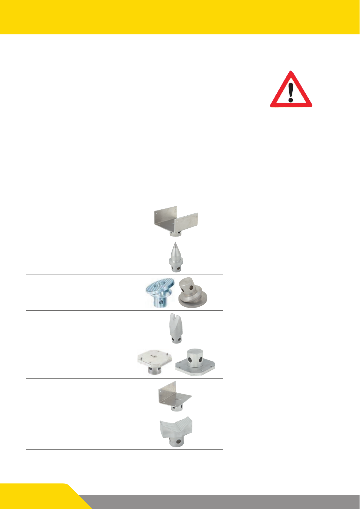
1.5.1 Attachments
The following attachments were developed for the most diverse applications.
The use of attachments depends on the material properties and the existing statics of the
object to be supported!
ART-CG 4, 100 mm
U - attachment
Point ART-PT
Corrective plate ART-SL 15 , 15°
Chain/wedge
attachment
Plate, smooth ART-FB
ART-CG 6, 150 mm
ART-CG 8, 300 mm
ART-CW
Angle attachment ART-LG
V-attachment ART-VB
Page 6/24
Corrective plate ART-SL 23, 23°
Pressure piece/
mandrel
Plate, ribbed ART-RB
ART-RH
Attachments are placed onto the piston rod of the ART strut and are xed and their direction locked with the aid
of the spring-loaded lock. The direction of the attachment, such as the V-attachment or angle attachment, must
be taken into consideration.
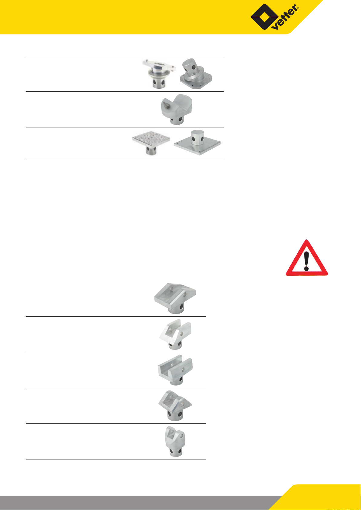
1.5.2 Angle Pieces
Angle pieces are required for connecting the base plates with the ART struts. Because of the dierent versions
available, the ART strut can be inserted into the relevant foot plate structurally on one side as well as on both
sides in an angled position.
When using the ART struts in the angled position it is imperative that a safety
device is used to prevent catapulting outwards! This can be in the form of square
timber and corresponding ground or, depending on the foundation, with screws
or bolts on the base plate.
Angle bracket ART-PC
45° clevis, single
sided
Static clevis ART-SC
45° clevis ART-C45
60° clevis ART-C60
ART-45SC
These clevises are positioned on the base plate with their function side and secured with the safety pin to the
base place.
Page 7/24
AIRSHORE Struts and Accessories for Rescue
Sicherungsstift
Sicherungsöse
Verriegelung Sicherungsstift
Bohrung mit Gewinde
Sicherungsstift
Anschlag
Sicherungsöse
Aufnahme für
The ART strut is positioned on the mounting head of the clevis
with the support tube and is also secured and locked by the aid of
the spring-loaded safety pin of the strut.
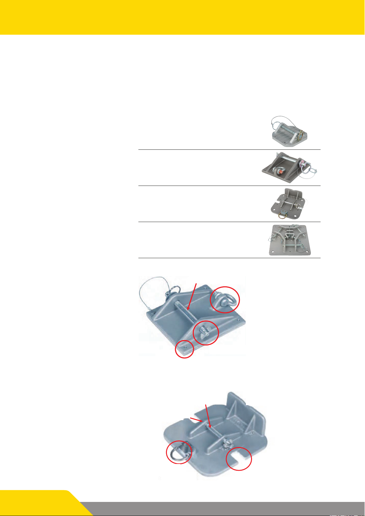
1.5.3 Base plate
Base plates for ART struts are supplied in three versions.
ART-BP5 base plate
120 mm
ART-BP6 base plate
150 mm
ART-BPB12 base
plate 300 mm with
bracket
ART-TH head plate
ART-BP6
is also used for the
Airshore rails, refer to
wall shoring
used for the highstrength column and
for the tripod.
Safety pin
Safety lug
Page 8/24
Threaded hole
ART-BPB12
Safety pin
Locking for safety
Verriegelung
Sicherungsstift
pin
Safety lug
Locking for safety pin
Bracket
Inlet for ground
Erdanker
anchors
 Loading...