

Vetter Pipe and Test Sealing Bags User Manual
Industrial Pneumatics.
Operating Instructions
VETTER Pipe and Test Sealing Bags
Art.-Nr. 9987044604 | © Vetter GmbH I 08/14 I Changes and errors excepted.

Vetter Pipe and Test Sealing Bags
Contents
1. Introduction ......................................................4
1.1 Symbols used ...............................................4
1.2 Correct handling and usage .................................4
2. Safety instructions ................................................5
2.1 General information ........................................5
2.2 Information about the dangers ..............................6
2.3 Warnings ...................................................6
3. Operation of Pipe and Test Sealing Bags ...........................7
3.1 Operation with controller, ination hose and compressed
air bottle ...................................................7
3.2 Operation with controller, ination hose and other
compressed air sources .....................................8
3.3 Operation with a foot pump having a safety valve ...........9
4. Operation of Pipe and Test Sealing Bags ...........................9
4.1 Preparations for operation ..................................9
4.2 Support structure ......................................... 10
4.3 Blocking a pipeline .......................................11
4.4 Emptying the pipeline ....................................12
4.5 Water test and compressed air test ........................12
4.6 Water pressure test (open channel) ........................ 12
4.7 Compressed air test ....................................... 13
4.8 Construction of a temporary bypass ....................... 14
5. Maintenance and care ..........................................14
5.1 Maintenance intervals ....................................14
6. VETTER Round Proles ..........................................16
Page 2/33
6.1 Vetter Mini Pipe Sealing Bags 2.5 bar ......................16
6.2 VETTER Mini
6.3 Vetter Pipe Sealing Bags 0.5, 1.5 and 2.5 bar ...............18
6.4 Vetter Test Sealing Bags 0.5, 1.5 and 2.5 bar ................20
6.5 Vetter Bypass Bags 1.5 bar. . . . . . . . . . . . . . . . . . . . . . . . . . . . . . . . . 22
6.6 Vetter House connection Testing system 2.5 bar ...........23
6.7 Vetter Test Sealing Bags for Gullies 1,0 bar ................. 24
6.8 Vetter Pipe Sealing Bags CR ............................... 25
Test Sealing Bags 2.5 bar. . . . . . . . . . . . . . . . . . . . . . . 17

6.9 Vetter Pipe Sealing Bags NBR .............................. 26
6.10 Vetter High Pressure Pipe Sealing Bags 6 bar ............... 27
7. VETTER Egg Proles ............................................. 28
7.1 Vetter Egg Prole Bags 1 & 1.5 bar .........................28
7.2 Vetter Egg Prole Testing and Bypass bags 1 & 1.5 bar ...... 29
8. Material and resistance charts ...................................31
8.1 Material list ............................................... 31
8.2 Temperature resistance ...................................31
8.3 Resistance chart ..........................................32
Important information
Owing to an increase in demand, all pipe and test sealing
bags will be tted with brass couplings as a standard from
01.01.2012 onwards.
If you still wish to have the safety couplings (blue at
1.5 bar, black at 2.5 bar), we kindly ask you to state
this explicitly when placing an order.
Page 3/33
Vetter Pipe and Test Sealing Bags
1. Introduction
The precondition for the safe use and the defect-free operation of
Vetter pipe and test sealing bags is the knowledge and the observance of this operating manual as well as the safety instructions.
DIN 7716 is to be adhered to in cases of long-term
storage.
In addition to this, the pertinent work protection regulations, work
safety regulations and accident prevention regulations are to be
observed the same as the generally recognized technology laws.
The operating instructions given here are to be regarded as part
of the product and are to be kept for the complete life duration of
the product. In case the product should be passed on to a successive user then the operating instructions must also be included.
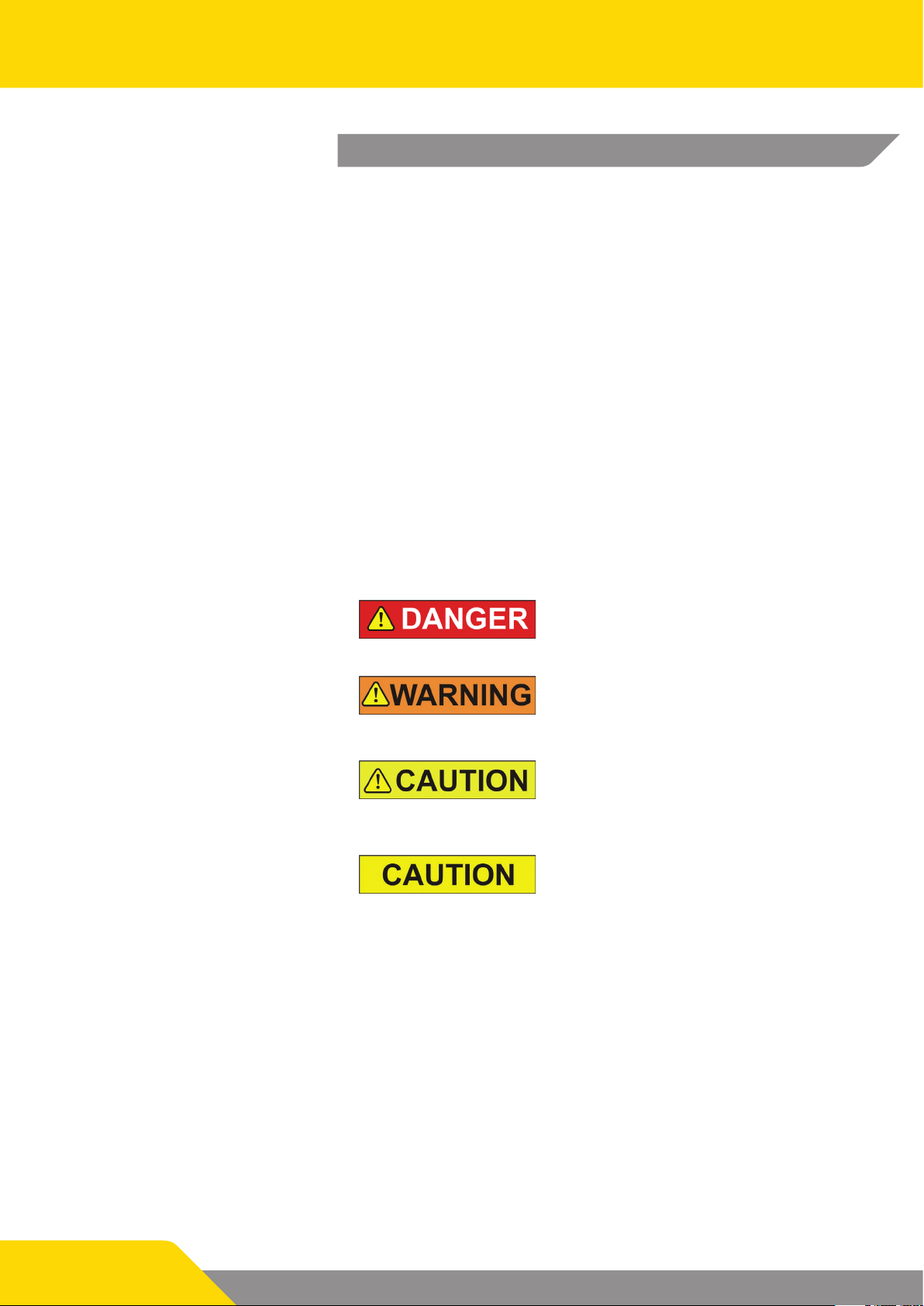
1.1 Symbols used
The following symbols are used in the text for dangers and warnings:
This symbol means that there is imminent danger. If it is not avoided then
death or serious injury will result.
This symbol means that there is a possible dangerous situation. If it is not
avoided then death or serious injury
could result.
This symbol means that there is possibly a dangerous situation. If it is not avoided then light injuries or slight injuries
could result.
This symbol means that there is the
possibility of damage being caused. If
it is not avoided then the product or
something else in its vicinity could be
damaged.
1.2 Correct handling and usage
Page 4/33
Vetter pipe and test sealing bags must, depending on the purpose of the task, only be inated with compressed air to the corresponding pressure level using original ination ttings.
Ination with ination ttings from another manufacturer is classied as contrary to the regulations for correct use.
They are exclusively used for blocking the intended pipes, for leak
sealing testing of pipelines and for construction of a bypass.
Any other application or use going beyond this is classied as
contrary to the regulations for correct use.

An application contrary to the regulations for correct use of Vetter
pipe and test sealing bags includes:
9 Incorrect use, operation or maintenance of pipe and test
sealing bags.
9 Use of the Vetter pipe and test sealing bags with defective
safety devices or incorrectly tted or non-functional ination
ttings.
9 Non-observance of the instructions given in the operating
manual concerning storage, operation and maintenance of
pipe and test sealing bags.
9 Insucient monitoring of accessory parts subject to wear.
9 Incorrectly carried out maintenance work.
Correct use according to regulations also includes
9 The observance of all instructions given in this operating ma-
nual.
9 The observance of the set periods for maintenance and care
specied in the chapter „Maintenance and Care“.
2. Safety instructions
The knowledge and observance of this operating manual are the
preconditions for the use of Vetter pipe and test sealing bags
2.1 General information
The observance of all pertinent work protection regulations and
safety regulations, accident prevention regulations (e.g. safety regulations from the technical authorities – TBG) as well as the recognized technical laws are to be carried out.
The pipeline is to be inspected for damage before using pipe and
test sealing bags. The area in the pipe for the pipe and test sealing
bag must be free of deposits, dirt and foreign bodies, such as fragments, sharp-edged objects etc.
Necessary personal protection devices must be made available:
protection clothing, cloves, helmets, facial and/or eye protection
etc.
Pipe and test sealing bags must be positioned full length in the
pipeline and with the sealing area on the inside wall of the pipe.
All pipe and test sealing bags (round and egg-shaped) must be
non-positively and positively positioned and tted.
Page 5/33
Vetter Pipe and Test Sealing Bags
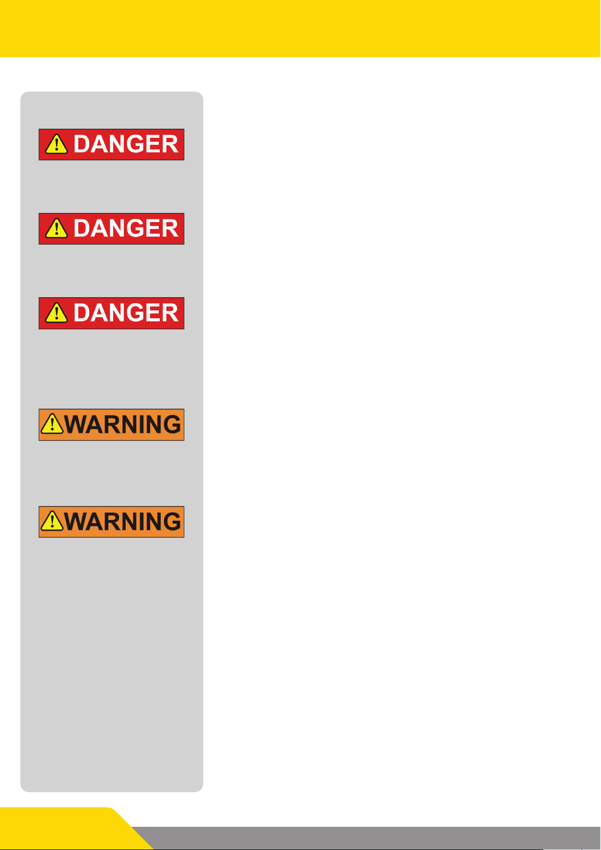
2.2 Information about the dangers
Changes and modications to the sealing bags, ination ttings
and ination hoses are not permitted. Operation of Vetter pipe
bags, test bags and bypass bags are only permitted with original
Vetter ination ttings and ination hoses. Parts made by another
manufacturer can inuence safety.
Pipe and test sealing bags are made of a strong expanding material. If this material is expanded beyond its permitted maximum
range then this can cause bursting. No person is allowed to remain within the working area during the pressure test. With a
water pressure test, the pipeline being tested must not have any
direct connection to a high-pressure line (e.g. hydrant).
After positioning the pipe and/or the test sealing bag it is to be
ensured that nobody remain in the channel or in front of the pipe
during ination, as well as during the test procedure and emptying sequence. Before removing the set-up make certain that the
pipeline is not under any pressure and is completely empty.
2.3 Warnings
The pipe and test sealing bags as well as the accessories must be
checked for perfect condition before and after each operation.
Outside the pipeline, Vetter pipe and test sealing bags, 0.5 bar and
1 bar, must only be lled to maximum 0.2 bar for the visual test.
1.5 bar and 2.5 bar bags must only be lled to a maximum of 0.5
bar.
All controllers are tted with a safety valve that has a permitted
maximum operating pressure corresponding to the pipe and test
sealing bag. If the maximum operating pressure of 0.5, 1.5, 2.5 or
6 bar is exceeded then the safety valve will activate. The tolerance
for opening and closing of the safety valve is only permitted to be
a maximum of + 10 %. The set pressure must not be changed. If
the sealing on the top part of the valve is removed then its operation is no longer guaranteed and the safety valve must be exchanged. The permitted inlet pressure on the controller (marking
on the inlet coupling) must not be exceeded.
Page 6/33
3. Operation of Pipe and Test Sealing Bags
This chapter informs you about which compressed air sources you
can use with the Vetter pipe and test sealing bags.
Observe the corresponding pressure level with
operation of pipe and test sealing bags
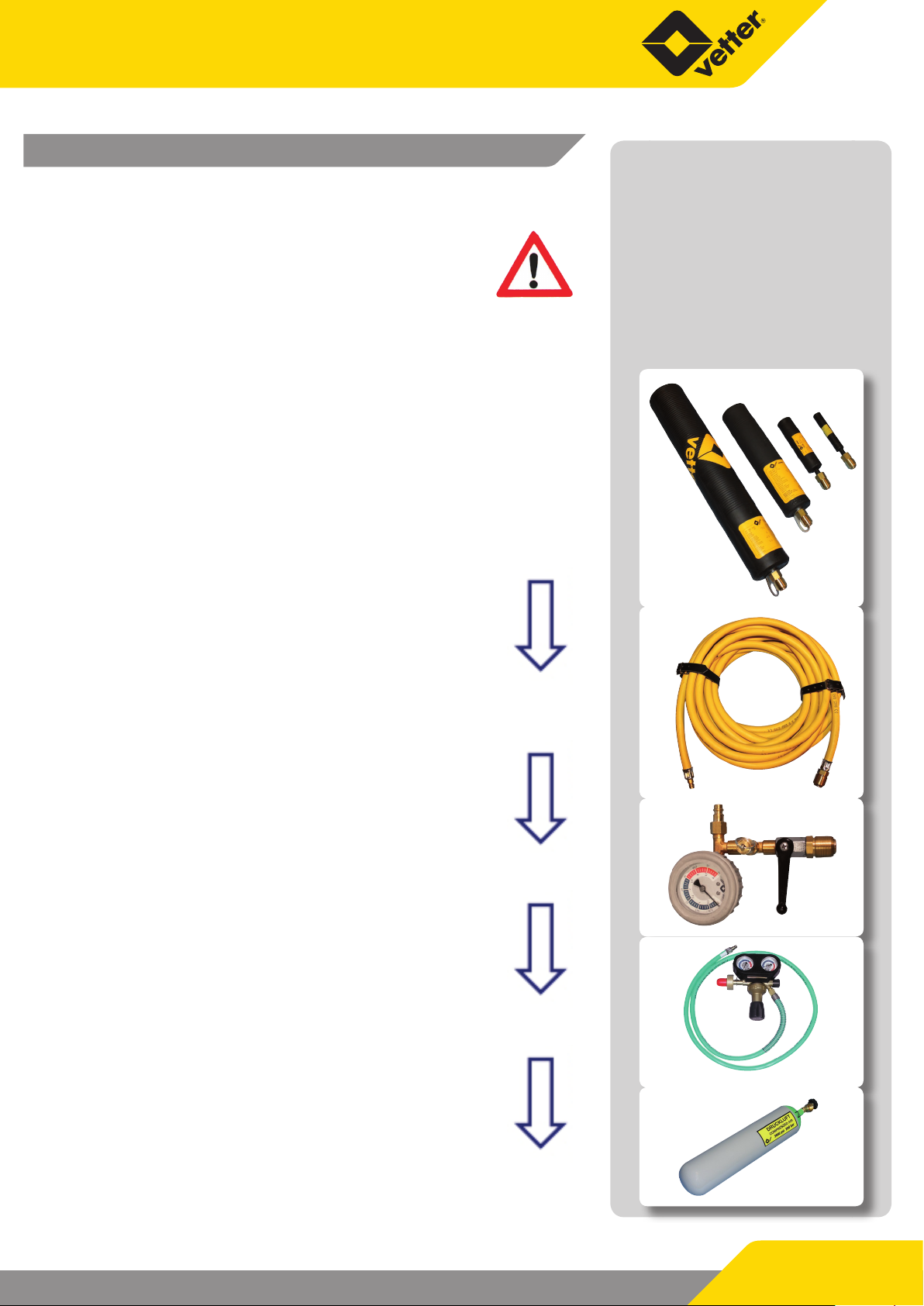
3.1 Operation with controller, ination hose
and compressed air bottle
Note! In the following presented gures the sequence of
events uses the pressure level of 2.5 bar as an example.
The corresponding bags and accessories must be used
for other pressure levels and other sources of air.
Pipe and test sealing bags
9 Step 1
Connect pipe and test sealing bags 2.5 bar to the
ination hose.
Ination hose
9 Step 2
Connect the ination hose to the controller.
The ination hose, the sealing bag and the controller
must have the same pressure level.
Controller
9 Step 3
Connect the connection hose of the pressure
regulator to the inlet coupling of the controller.
In doing this it is imperative that the permitted inlet
pressure of the controller is observed
Pressure regulator
9 Step 4
Screw-in the connection thread of the pressure
regulator into the inside thread of the valve on the
compressed air bottle.
Compressed air bottle
Page 7/33
Vetter Pipe and Test Sealing Bags
3.2 Operation with controller, ination hose
and other compressed air sources
Observe the maximum inlet pressure from the
compressed air source for the dierent
pressure levels (refer to the table below).
Truck compressed
air connection
Adapters in the adapter set
Applied pressure level Maximum inlet pressure
of the compressed air source
0.5 bar 2 bar
1.0 bar 2 bar
1.5 bar 2 bar
2.5 bar 4 bar
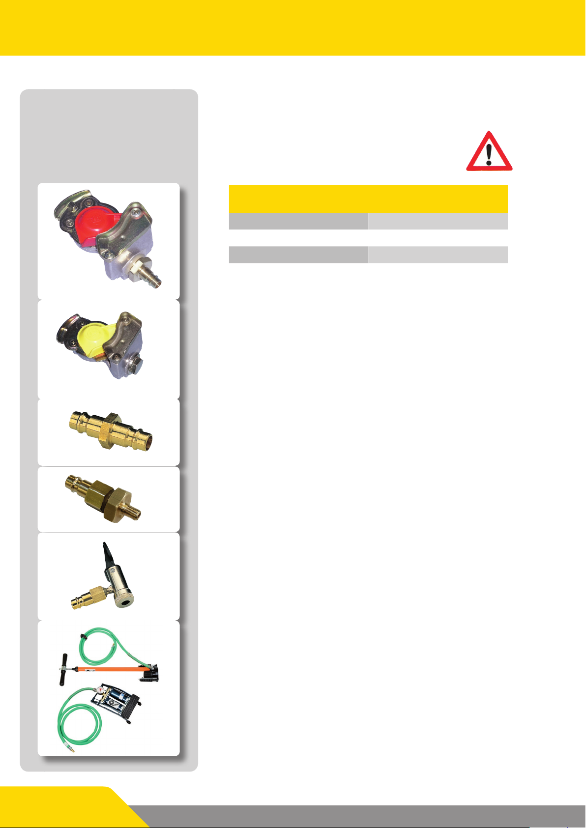
Dummy coupling
The adapter set contains adapters for the following air sources:
Truck compressed air connection and dummy coupling
Close the control line with the dummy coupling.
Local compressed air network
Connection on the output coupling of a compressed air network.
Truck tyre valve
For ination with a normal hand pump or foot pump
Truck tyre valve connection
For taping o air from a spare wheel.
Page 8/33
Hand pump and foot pump
Hand pump or foot pump with 2 m connection hose to the connection onto the inlet coupling of a controller. Hand pump and
foot pump do not belong to the delivery package of the adapter
set.
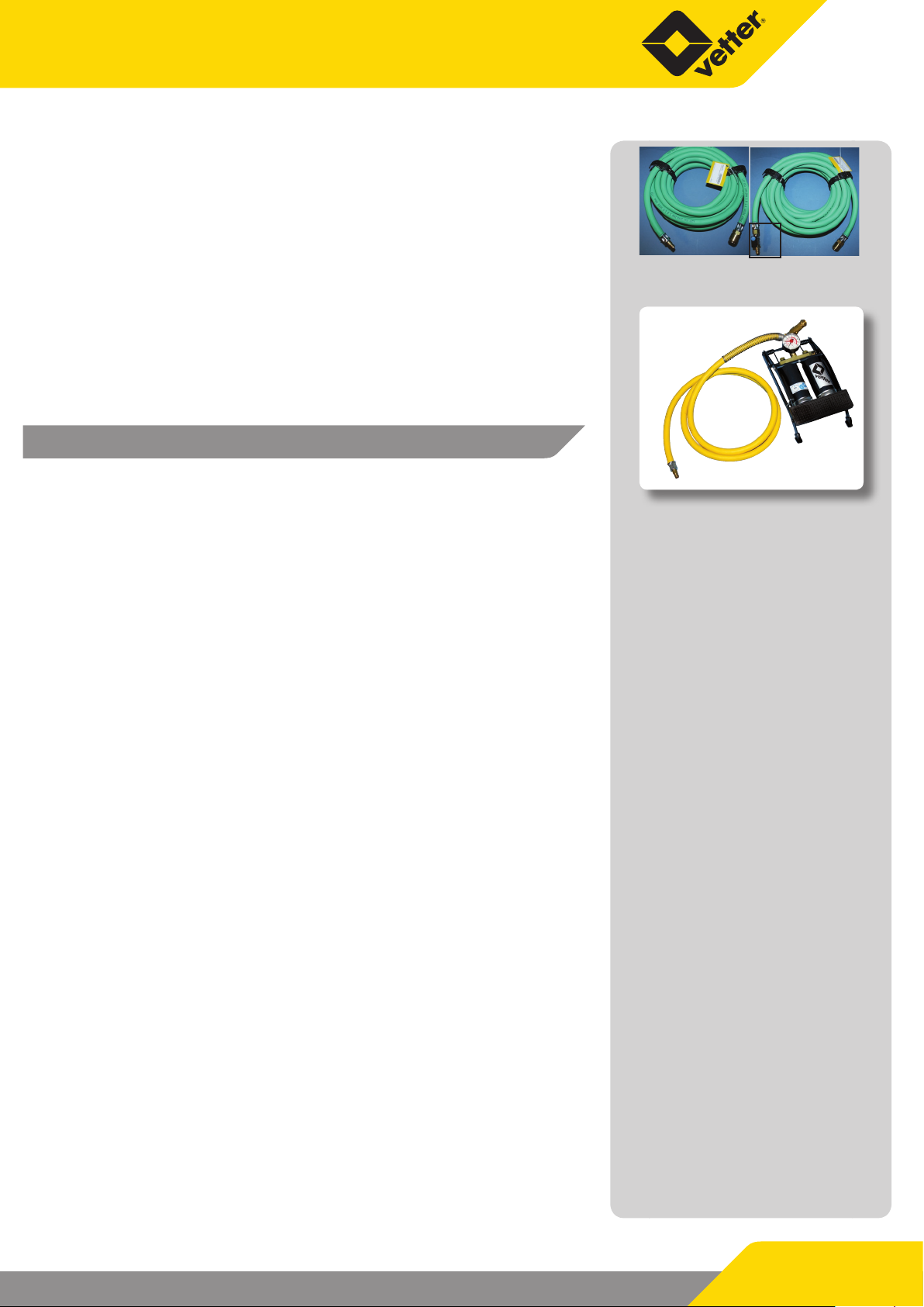
Air supply hose, 10 m, with and without blocking valve
The air supply hoses, with and without blocking valve, can be used
as an extension between the air source and the controller.
3.3 Operation with a foot pump having a
safety valve
Foot pump 2.5 bar with safety valve
Foot operated air pump 2.5 bar with safety valve and 2 m connection hose for ination of sealing bags in connection with an
ination hose.
4. Operation of Pipe and Test Sealing Bags
In this chapter you will nd out how the Vetter pipe and test
sealing bags are applied.
When using the pipe and test sealing bags, observe the
safety instructions given in chapter 2 as well as the pertinent regulations for work protection and safety protection, accident prevention regulations (e.g. the safety
regulations of the technical authorities -TGB) and the generally recognized laws of technology.
4.1 Preparations for operation
with blocking valve
Foot pump 2.5 bar with safety valve
9 Ensure that only authorized sta are in the working area and
danger area.
9 Select a suitable pipe and/or test sealing bag which corres-
ponds to the requirements.
9 Check the bag and the accessories to be used for complete-
ness and damage.
9 Damaged bags and damaged accessory parts must not be
used!
9 The bag diameter must be smaller than the inside diameter of
the pipeline.
9 Ination hose and controller must already be connected to
the sealing bag.
9 Mark the working area.
9 Position the bag (full length) into the pipe.
9 The sealing bag in the pipe is to be supported.
9 Draw the sealing bag to the support structure and inate so
that it can still be moved in the pipeline.
9 The support structure should be made so that the sealing bag
can be supported over a large area.
Page 9/33
Vetter Pipe and Test Sealing Bags
9 Leave the shaft and/or pipeline.
9 Make certain that no sta remain in the area of danger.
9 Inate the sealing bag to the permitted maximum operating
There is a danger of the bag catapulting outwards. The pressure
or water column must be completely reduced within the pipeline
before the support structure is removed. Otherwise the sealing
bag could catapult outwards.
After completion of the work, pressure reduction is to be carried
out via the ination hose (ventilation nipple) or the controller
(pressure reduction via the knurled screw of the safety valve).
Generally this must be made outside the pipeline or shaft.
9 If the water has completely owed out of the shaft / pipeline
pressure from a safe position.
then release the compressed air out of the bag.
9 Now remove the support structure and take the bag out of
the shaft/ pipeline.
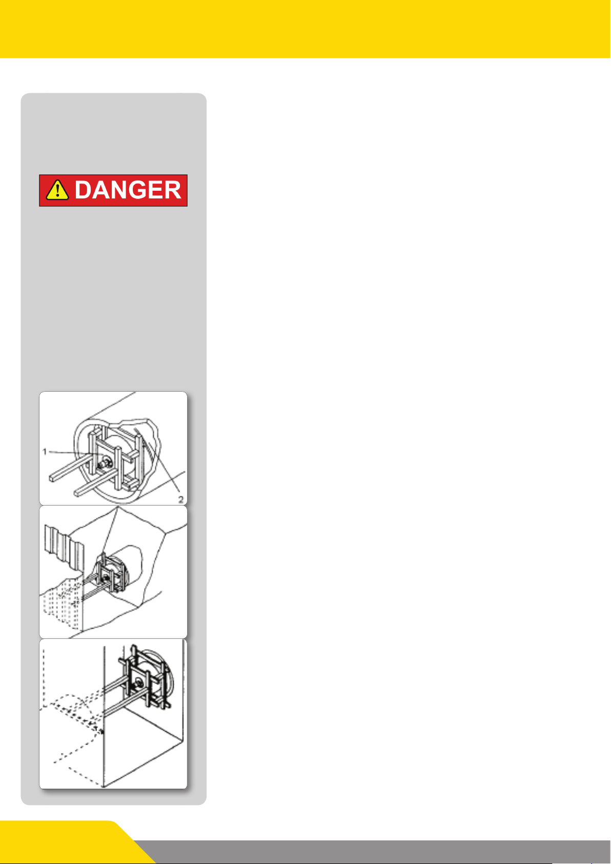
4.2 Support structure
The type of support structure depends on the structural factors in
the pipe, the pipe itself and the counter-pressure to be expected.
The following support possibilities are only drawing diagrams and
are given as examples.
General details of support (presented as a diagram)
1 Bag centre
2 Inatable bag sleeve
Support suggestion for a ditch
(presented as a diagram)
Page 10/33
Support suggestion for a street inlet shaft
(presented as a diagram)
 Loading...