

Page 1
Emergency Pneumatics.
Operating Instructions
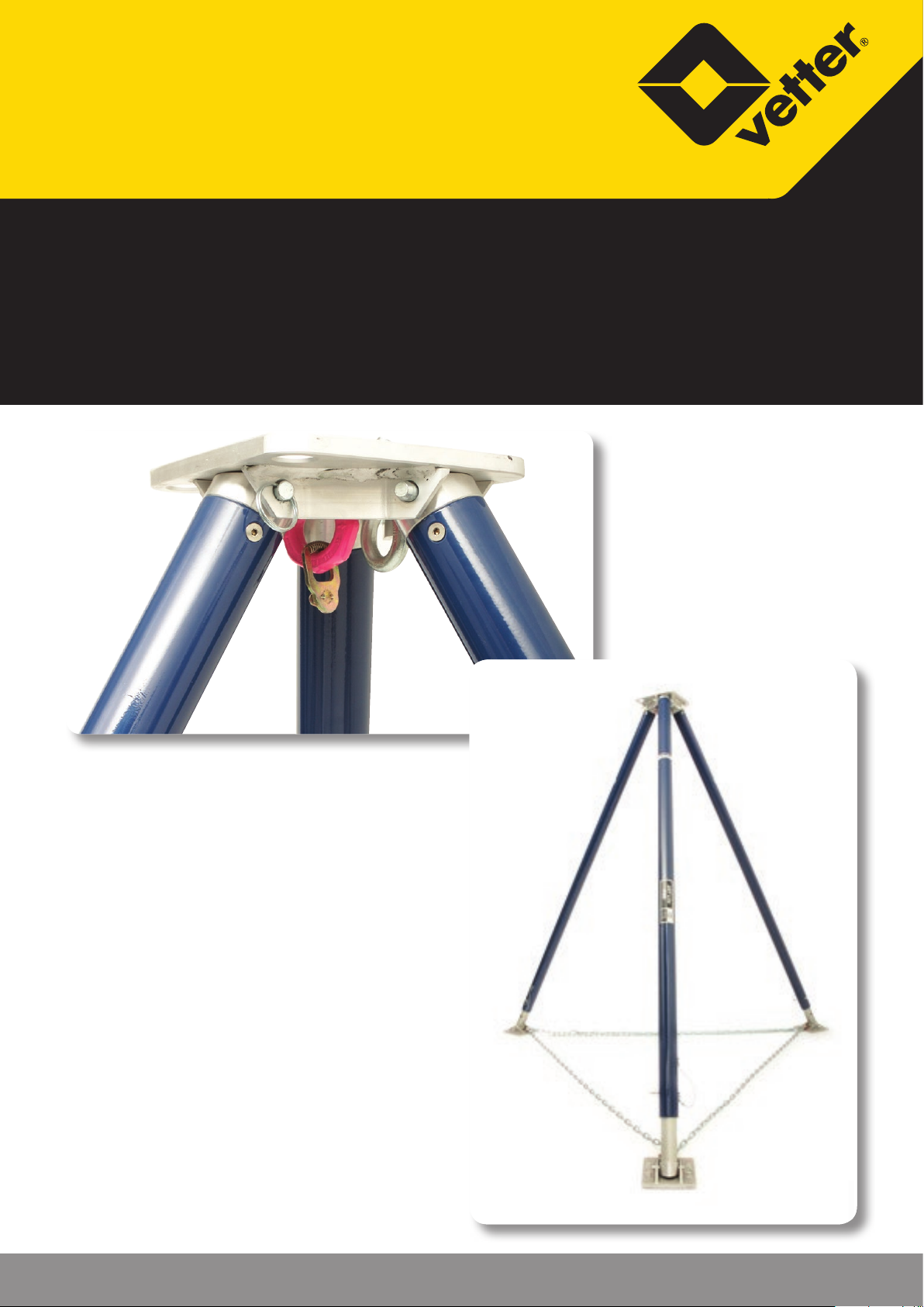
ART Lite Pod
Article No. 9987050101 | © Vetter GmbH I 07/14 I Changes and errors excepted.
Page 2

ART Lite Pod
Contents
1. Important preliminary remarks ....................................3
2. Marking ..........................................................3
3. Product description ...............................................4
3.1 Set compilation .............................................4
3.2 Scope of application ........................................5
3.3 Check the equipment .......................................6
3.4 Safety instructions ..........................................6
4. Preparing for use ..................................................7
4.1 Mission preparation ........................................7
5. Operating instructions ............................................8
5.1 Assembling the ART Lite Pod ...............................8
5.2 Dismantling ................................................9
5.3 Care, maintenance, storage .................................9
6. Documentation ................................................. 10
7. Guarantee ......................................................10
8. Technical Data .................................................11
8.1 Technical Data ........................................... 11
9. Spare parts ART Lite Pod Litepod ................................12
EC Conformity Declaration .........................................13
Page 2/14
Page 3
1. Important preliminary remarks
Solely the knowledge of and exact abidance with these operating instructions guarantee proper and appropriate deployment, bring the greatest
possible benets and secure any claims in the frame of the Vetter guarantee.
ART Lite Pod and accessories may be utilised solely by instructed and reliable persons. Every deployment/operation of the ART Lite Pod and its accessories assumes exact knowledge of and compliance with these operating
instructions.
Consider these operating instructions as a component of the product and
retain them during the product life cycle. If the product is transferred, pass
on the operating instructions to the subsequent user.
If the equipment will be sold in or passed on to another country the reseller
must provide the instructions for the use, the maintenance, the regularly
scheduled checks and the corrective maintenance in the language of the
other country.
The anchoring devices will be tested in accordance with EN 795 and are
intended for use by an individual person with the energy absorbers in accordance with EN 355 and a connector as per EN 354.
2. Marking
Manufacturer Vetter GmbH
Product name ART Lite Pod,
Type and Model ART Lite Pod
Serial no. e.g. 01121234
01121234
01 = Month of manufacture January
12 = Year of manufacture 2012
1234 = Consecutive no.
EN Standard/Year/Class EN 795:1996
CE mark and Reference no. of the acredited
laboratory, which is intervened with the
type test/Contact
-0158
DEKRA EXAM GmbH
Prüaboratorium für
Bauteilsicherheit-Seilprüfstelle
Dinnendahlstr. 9
D-44809 Bochum
Code number: : 0158
Symbol, which demands to read the operating instructions
Max. number of persons 1 Person
Page 3/14
Page 4
ART Lite Pod
3. Product description
9 The ART Lite Pod comprises 5-cm (2 inch) thick round tubes
made of high-strength aluminium (6061-T6) and was powder
coated to guarantee the durability and a long service life.
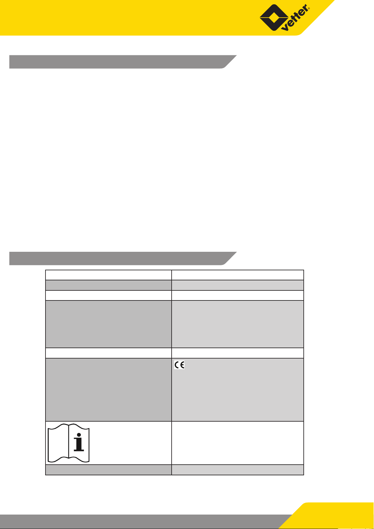
9 The ART Lite Pod can be adjusted from 183 - 305 cm
(72 - 120 inch).
9 Use solely the silver eyelet for the fall safeguard. The pink eye-
let must not be used for this type of use! The silver eyelet is
permanently xed and is used as a slinging point as the personal fall safeguard.
9 The head plate of the ART-LP has two drill holes with 2.5 cm
(1 inch) diameter to guy the construction.
9 The drill holes in the struts are numbered to ease precise
alignment.
9 Red markings on the struts mark the maximum extension
length.
9 Secure the ART-LP by attaching the safety chain
9 The ART Lite Pod tripod struts are secured by the base plates
against sinking in. The load distribution makes the tripod stable and safe.
3.1 Set compilation
Set compilation ART Lite Pod
Article No. 7200011101
Article No. Product description Quantity
Strut, adjustable from
7200033800
1830 - 3050 mm
(72 - 120 inch)
3
Page 4/14
Page 5
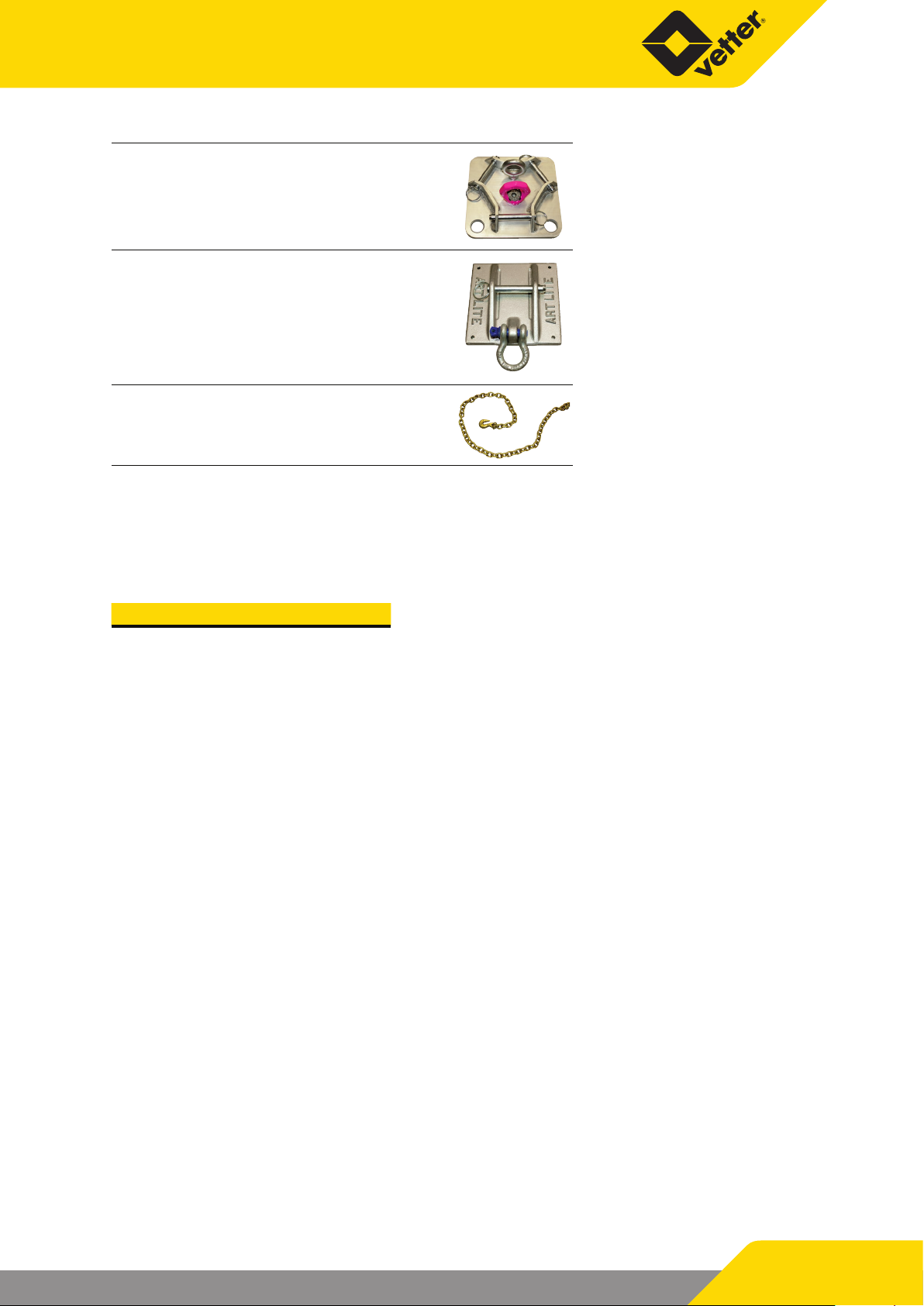
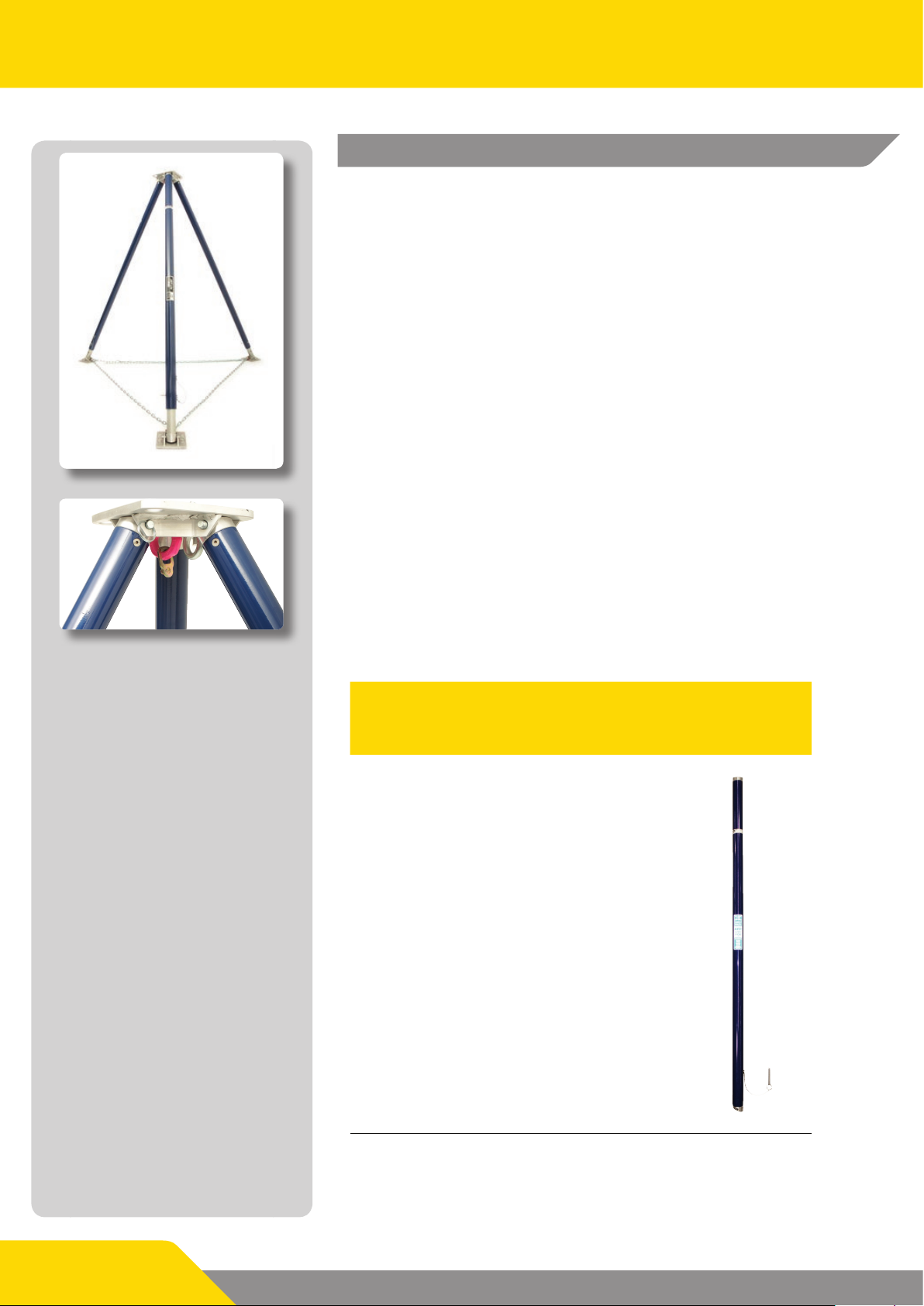
7200033900
Head attachment for
Tripod, light
ARL base plate 6”
150 mm (6 inch)
1
7200035500
7200035600
The base plates have
to be secured to each
other with a safety
chain against slipping.
Safety chain with quick
release fastener
3
1
Solely a body harness in accordance with EN 361 is permitted to be used in this personal protective equipment
system!
Additional accessories:
Article No. Description
7200011200 ART-LPC carrying case 1
3.2 Scope of application
The ART Lite Pod with its light weight and its small pack size is ideal for use in shaft, height, ditch and mountain rescue operations.
As an anchor construction the rescuer can, for example, secure it
while accessing a shaft, when rappelling from buildings or in the
mountains.
The equipment is allowed to be used solely within the stipulated
conditions of use and for the intended application.
Page 5/14
Page 6

ART Lite Pod
3.3 Check the equipment
Please make sure that:
9 The carabiner snap hooks do not exhibit any signs of dama-
ges.
Visual inspection
Carabiner snap hooks
Performance test
Headpiece for tripod Visual inspection
Base plate for tripod Visual inspection
9 The carabiner snap hooks are not bent.
9 The thumbscrew threads are clean and do not show any
signs of damages.
9 The bolts of the movable leg are present and tightly seated.
Please make sure that:
9 The movable leg is under spring tension.
9 The thumbscrew can be turned without any resistance
9 The swivel closure returns to its blocking position.
Please make sure that:
9 The headpiece is clean
9 The headpiece, the coupling ring and the eyelets along with
the securing pins are not bent
9 The nuts of the rigid eyelet are tightened with 34 Nm (301
lbf in) and the pink eyelet with 75 Nm (664 lbf in)
Please make sure that:
9 The base plates are clean
9 The base plates, the eyelets and the securing pins are not
bent
Please make sure that:
Safety chain for tripod Visual inspection
Tripod supports Visual inspection
9 The safety chain is clean
9 The safety chain including the carabiner hooks is not bent
Please make sure that:
9 All supports and cylinders (extendible part of the support)
are clean
9 No supports and cylinders are bent
9 All cylinders glide smoothly in the supports
9 The securing pins on the supports are not bent or damaged
3.4 Safety instructions
The ART Lite Pod may be used solely by qualied and trained persons who are familiar with corresponding
devices and situations! Only those persons are authorised from whom it can be expected that they perform their work reliably. Persons whose responsiveness is inuenced by, for example, drugs, alcohol, use of
medicines or illness are not authorised since these factors impair safety. People who are not involved are
not permitted to stay in the work area and must be instructed to leave the work area.
During deployment, compliance with all relevant accident prevention and occupational safety regulations
is mandatory.
Page 6/14
Page 7
Before deployment, make sure that the ART Lite Pod is complete and in
a awless condition. Please ensure that all parts of the system are in
awless condition. Even just one defective part can impair the reliable
functioning of the entire system. The ART Lite Pod must not be used if
there are signs of damage or if you have doubts about the awless condition.
If the equipment has been stressed by a fall, the written consent of an expert person is required before the equipment can be deployed again.
A plan must be available about the rescue measures and the plan must be
taken into consideration when working on possible emergencies.
Do not make any modications or undertake any supplements on the
equipment without prior, written consent from the manufacturer. Likewise,
perform corrective maintenance only in compliance with the measures stated by the manufacturer.
If you have any specic questions or doubts about the safety of the ART Lite
Pod, please get in touch with Vetter GmbH.
Caution! Check and if applicable re-tighten all
threaded connections before the deployment!
4. Preparing for use
4.1 Mission preparation
9 Check the local circumstances and adapt the strut length accordingly.
9 Get all parts of the set plus the accessories such as the karabiner snap
hooks, guide pulleys and cable winches ready.
9 Please make absolutely sure that there is sucient space underneath
the user before each deployment to denitely exclude any possibility of
an impact on the ground or on another obstacle in case of a fall.
9 Please also note that the free fall is restricted to the minimum.
9 Make sure the slinging point is above the user.
9 The following hazards can impair the functioning of the equipment and
must always be avoided: e.g., extreme temperatures, stress on the connectors due to sharp edges, slack ropes, eects of chemicals, electrical
inuences, cuts, abrasion, climatic impacts, oscillating motions during
falling.
Page 7/14
Page 8
ART Lite Pod
Fig. 1
Fig. 3
Fig. 2
5. Operating instructions
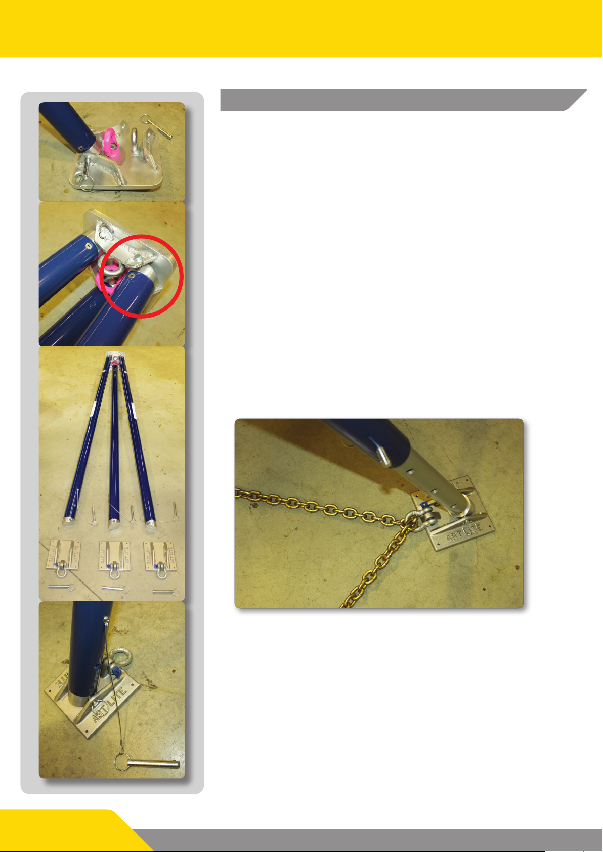
5.1 Assembling the ART Lite Pod
9 First use the bolts on the head piece to attach the struts to the
non-extendible side as can be seen in Figs 1 + 2. Make sure
that the chamfered side of the strut head faces the outside.
(See marking)
9 Then fasten the extendible strut ends with the bolts to the
base plate (Fig. 3). While doing so, make sure the eyelets of
the plates and the chamfered side of the strut ends are facing
towards the inside (Fig. 4).
9 The base plates can be secured against slipping with faste-
ning elements that are suitable for the substrate.
9 To correspondingly adjust the height of the struts to the de-
ployment situation, extend the struts manually and arrest
them at the desired height using the bolts. The numbering of
the holes helps with the orientation.
9 Finally, the tripod needs to be secured against slipping/splay-
ing with the provided chain. To accomplish that, lead the
chain through the rings (Fig. 5) and clamp the chain accordingly. After that, hook the chain lock together. (Fig. 6)
Fig. 4
Page 8/14
Fig. 5
Page 9
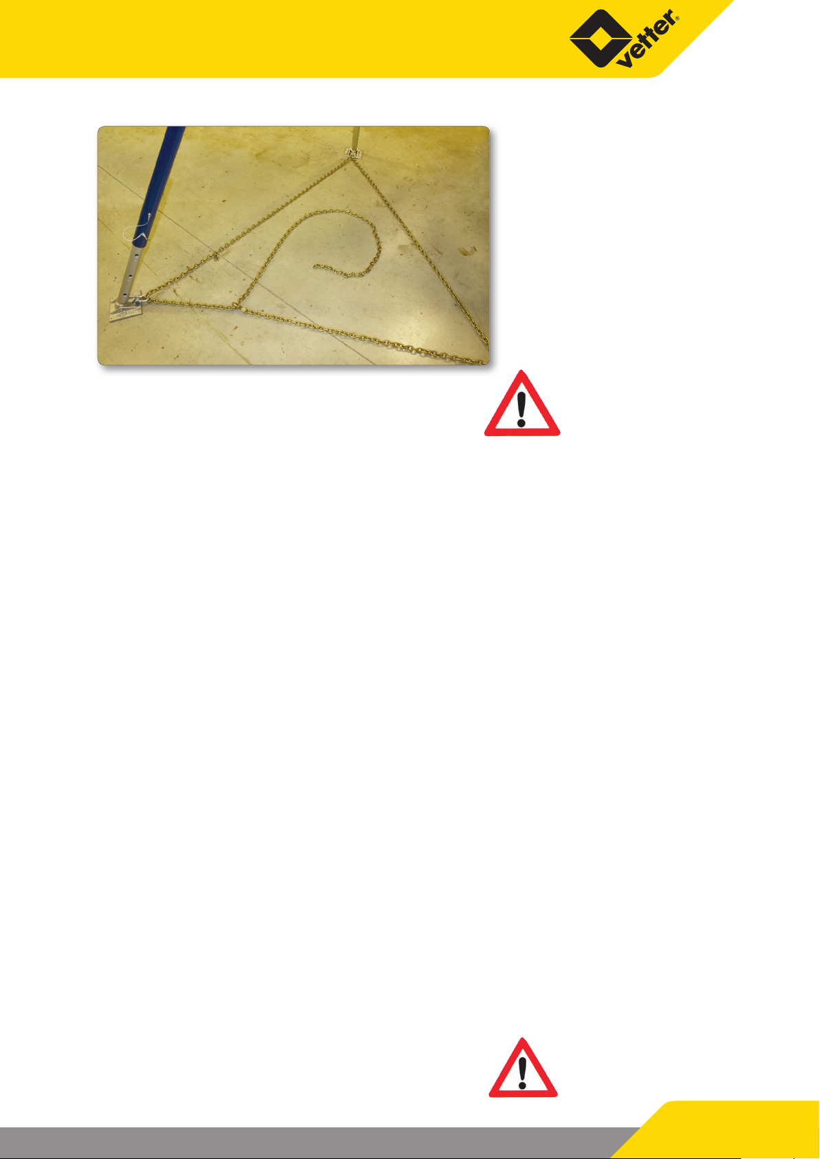
Fig. 6
Use suitable measures to secure the base plate
against slipping! (E.g. nails, screws)
5.2 Dismantling
Dismantle in the reverse order of setup.
5.3 Care, maintenance, storage
The user‘s safety depends on the eectiveness and the durability of the
equipment.
Store all the equipment together in the packing bag in a cool and dry location. Protect the equipment against sharp edges, direct heat, moisture,
vibrations and ultraviolet degradation!
Have an expert undertake a visual inspection and performance test of the
ART Lite Pod and the accessories and check them for completeness and intactness while precisely following these instructions before and after each
use and/or deployment but in any case at least once annually.
1. Pull the piston out of the strut tube.
2. Free the tripod and the accessories from dirt by washing with a washing brush and detergent and, if heavily soiled, possibly also with a
high-pressure jet cleaner.
3. Check the tripod and accessories for damages, completeness and
functioning!
4. Locking - Smoothness of operation and functioning
5. Reassemble the piston and strut tube and check for awless functioning and smoothness of operation.
6. The accessories - head plate and base plates also need to be regularly
inspected!
7. Above all, make sure that all adjusting bolts, securing pins, nuts and
locks are present and work awlessly!
8. Also check the legibility of the product identication!
Tighten the pink eyelet with 75 Nm (664 lbf in) and
the nut of the rigid eyelet with 34 Nm (301 lbf in)!
Page 9/14
Page 10

ART Lite Pod
6. Documentation
Perform and document the individual tests in accordance with the test instructions in these operating instructions. The documentation must include the points listed below and could look like this:
DOCUMENTATION OF THE EQUIPMENT
Product
Type and model/identication
Serial number
Year of construction
Trade name
Dealer
Address
Telephone and fax no.
E-mail
Date of purchase
Application
Date of the rst usage
Other important tasks
SEQUENCE OF THE REGULARLY SCHEDULED TESTS AND CORRECTIVE MAINTENANCE
Date Reason for pro-
cessing (regularly
scheduled test or
corrective maintenance)
The institution to which the user belongs is responsible for the documentation and the entry of the required
statements.
Damages found,
performed corrective maintenance
and other important
tasks
Name and signature
of the expert
Date of the next test
7. Guarantee
We cover material and defects in workmanship of all Airshore products with a warranty of 2 years from the date of
purchase. Airshore products which come under this warranty will be repaired or replaced after a corresponding
inspection. Warranty claims are managed by our contract dealers or Vetter GmbH.
Damages caused by incorrect or impermissible handling are not covered by this
warranty!
Page 10/14
Page 11

8. Technical Data
8.1 Technical Data
ART Lite Pod
Material Aluminium
Expansion diameter
Deployment height
Installation height
Load-bearing capacity
at max. height of 305 cm (120 inch)
Load-bearing capacity
at height of 183 cm (72 inch)
Weight approx.
All rights reserved for technical changes within the scope of product improvement.
2.65 m
104.3 inch
183 - 305 cm
72 - 120 inch
≤ 350 cm
≤ 137.8 inch
318 kg (Safety factor 10:1)
701 lbs
454 kg (Safety factor 10:1)
1001 lbs
32 kg
70.5 lbs
Load-bearing capacity at:
0 - 45° = 4 t (4.4 US tons),
> 45° = 1.5 t (1.6 US tons)
Strut material:
The ART Lite Pod comprises 5 cm (2 inch) thick round tubes made
of high-strength aluminium (6061-T6) and was powder coated to
guarantee the durability and a long service life.
Page 11/14
Page 12

ART Lite Pod
9. Spare parts ART Lite Pod Litepod
AIRSHORE LITE POD Parts List
Model Number: 368A062
ART-LPBC BARREL CLEVIS
K2-12WASHER WASHER
K2-500N HEX NUT
179A034 JAM NUT
267A066 WASHER
K2-1412 SCREWS
LOAD CAPACITIES
At 6 feet = 1,000lbs
At 10 feet = 700 lbs
10:1 SAFETY FACTOR
K2-1414BHSC SCREW
132A122 DECAL
107A049 BARREL
364A029
25' CHAIN w/GRAB HOOK
315A001 LANYARD
189A083
PIN
189A083 PIN
195A052 LITE POD LID
CW-58-EYE SWIVEL EYE
CW-12112EYE EYEBOLT
Load should always be
centered below top plate
ART-LPPR PISTON
ARL-LPPC
PISTON CLEVIS
K2-1412 SCREWS
189A083 PIN
ARL-BASEPLATE6
BASE PLATE
305A019
SHACKLE w/SCREW PIN
Page 12/14
Lite Pod should always be used
with the safety chain in place
AirShore products have precise assembly
specifications. Parts lists and diagrams are
for reference and part identification only.
Any and all modifications and repairs should be
performed only by factory trained personnel.
Form Part No. 172A304 Rev. 03
Page 13

EC Conformity Declaration
in accordance with Directive 89/686/EWG
Manufacturer name and address
Hurst Emergency Products
A Unit of IDEX Corporation
711 N. Post Road
Shelby, NC , USA 28150
We hereby declare, that the ART Lite Pod
Serial-No.: __________________
Model: __________________
(refer to equipment label, to be entered by the customer)
meets the following applied standards or other normative documents:
EN 795:1996
Authorised representative for the compilation of technical documents:
Vetter GmbH
Blatzheimer Str. 10 - 12
53909 Zülpich
GERMANY
Involved Notied Body during the EU type approval test:
DEKRA EXAM GmbH
Prüaboratorium für Bauteilsicherheit-Seilprüfstelle
Dinnendahlstr. 9
D-44809 Bochum
This EC Conformity Declaration was issued:
Zülpich, 10.12.2012
(Place, Date, Signature)
Page 13/14
Page 14

Place your trust in emergency pneumatics!
We are the company who can help you, nd a solution to your problem!
Vetter GmbH
A Unit of IDEX Corporation
Sales
Blatzheimer Str. 10 - 12
D-53909 Zülpich
Germany
www.vetter.de
Tel.: +49 (0) 22 52 / 30 08-0
Fax: +49 (0) 22 52 / 30 08-590
Mail: vetter.rescue@idexcorp.com
Article No. 9987050101 | © Vetter GmbH I 07/14 I Changes and errors excepted. I Made in Germany
Page 15

Emergency Pneumatics.
Operating instructions addendum
Rope winch/Rescue lifting device
Article No. 9987061600 | © Vetter GmbH I 07/14 I Changes and errors excepted.
Page 16

Rope winch/Rescue lifting device
Contents
1. Important preliminary remarks ....................................3
2. Marking ..........................................................3
3. Product description ...............................................3
3.1 Set contents ................................................4
3.2 Scope of application ........................................4
3.3 Check the equipment .......................................5
3.4 Safety instructions ..........................................5
4. Preparing for use ..................................................7
4.1 Mission preparation ........................................7
5. Operating instructions ............................................8
5.1 Assembly of the rescue lifting device, AT200/3 ...............8
5.2 Dismantling .............................................. 10
5.3 Transport and shipping ................................... 11
6. Documentation ................................................. 12
7. Warranty ....................................................... 12
8. Technical Data ..................................................13
EU conformity declaration Rope winch/rescue lifting device ......... 14
Page 2/15
Page 17

1. Important preliminary remarks
Solely the knowledge of and exact following of these operating instructions guarantee proper and appropriate deployment, bring the greatest possible benets
and meet the requirements contained within the scope of the Vetter guarantee.
Only instructed and qualied specialists are permitted to use the AT200/3 winch.
Every deployment/operation of the winch and its accessories assumes exact
knowledge of and compliance with these operating instructions.
Consider these operating instructions as a component of the product and retain
them during the product life cycle. If the product is passed on, give the operating
instructions to the subsequent user.
If the equipment will be sold in or passed on to another country, the reseller must
provide the instructions for the use, maintenance, regularly scheduled checks and
corrective maintenance in the language of the other country.
The rescue lifting device was certied in accordance with EN 1496 Class B.
2. Marking
Manufacturer PROTECTA International
Product description Rescue lifting device AT200
Type and Model Rescue lifting device AT200
Rope length 20 m
Serial no. e.g. 1238286
Month of manufacture e.g. 12
Year of manufacture e.g. 12
EN Standard/Year/Class EN 1496 Class B
Maximum utilization load 136 kg max
3. Product description
The AT200/3 rescue lifting device can be used together with the tripod, light ART
Lite Pod. The rescue lifting device is made of galvanized steel and has a black epoxy coating. The rescue lifting device is equipped with a hold-back as well as with
a self-blocking brake. The stainless steel rope has a length of 20 m, a diameter of 5
mm and is equipped with a swivel snap hook.
The reduction ratio is 4.5:1. The mean lift is 10 cm / revolution.
There are two locking bolts on the device to attach the tripod to the rescue lifting
device.
Page 3/15
Page 18

Rope winch/Rescue lifting device
3.1 Set contents
Set Winch for ART Lite Pod, Item no. 7200040001
Item no. Name
7200000201
Winch for ART Lite Pod,
including bracket
1
7200039201
Role for wire rope incl.
snap hook
1
3.2 Scope of application
This rescue lifting device
9 must be used solely for the evacuation of one single person
9 must be used solely for evacuation and rescue work.
9 has a maximum service load of 136 kg
9 must not be put into operation if it has come into contact with chemical or
corrosive agents.
Use/deploy this lifting device to hoist persons only if the
person to be hoisted is secured against falling with
personal protective equipment at the same time!
The equipment is allowed to be used solely within the
stipulated conditions of use and for the intended
application.
Page 4/15
Page 19

3.3 Check the equipment
ATTENTION: Protective gloves and safety footwear must be worn also during
maintenance work to prevent injuries!
Make sure that:
Carabiner snap hooks
Rope Visual inspection
Strength of the rope
connection on the drum
Visual inspection
Functional check
Visual inspection
9 The snap hooks, especially the automatic locking system,
does not exhibit and damage.
9 The carabiner snap hook is not bent.
Make sure that:
9 The proper rotational movement of the pivot pin is en-
sured.
9 The moving parts are under spring tension and do not
block.
Make sure that:
9 The rope does not exhibit any indented points, torn th-
reads, uncoilings/untwists, bends, heat damage (welding
points), oxidations.
If any single one of these defects is noticed, immediately take
the lifting device out of service.
Make sure that:
9 The connector is correctly attached to the drum disc
(completely free of play) and that the rope end projects
more than 2 cm past the connector.
Do not use the lifting device if there are any doubts about
the awless rope attachment.
Make sure that:
Mounting hardware Visual inspection
9 The mounting hardware (bolts) is in awless condition.
If these checks leave any doubts, or if the winch has been exposed to a violent eort due to a fall, return it immediately to Vetter GmbH.
3.4 Safety instructions
The AT200/3 rescue lifting device may be used solely by qualied and trained persons who are familiar with
corresponding devices and situations! Only persons from whom it can be expected that they perform their work
reliably are approved. Persons whose responsiveness are inuenced by, for example, drugs, alcohol, use of medicines or illness are not permitted since these factors impair safety. People who are not involved are not permitted
to stay in the work area and must be instructed to leave the work area.
During deployment, compliance with all relevant accident prevention and occupational safety regulations is
mandatory.
During deployment, wear protective gloves and safety footwear to prevent injuries.
Before deployment, make sure that the AT200/3 rescue lifting device is complete and in a awless condition. Ple-
ase ensure that all parts of the system are in awless condition. Even if only one part is defective, the safe
and reliable functioning of the entire system can be impaired. The AT200/3 rescue lifting device must not be
used if there are signs of damage or if you have doubts about the awless condition.
Page 5/15
Page 20

Rope winch/Rescue lifting device
If the equipment has been stressed by a fall, the written consent
of an expert person is required before the equipment can be deployed again.
A plan of the rescue measures must be available and the plan
must be taken into consideration when working on possible
emergencies.
Do not make any modications or additions to the equipment without prior, written consent from the manufacturer. Likewise, perform corrective maintenance only in compliance with the measures stated by the manufacturer.
If you have any specic questions or doubts about the safety of
the AT200/3 rescue lifting device, please get in touch with Vetter
GmbH.
ATTENTION: Check and if applicable re-tighten all
threaded connections before the
deployment.
CAUTION:
9 Do not change cable and check that the cable in place is free
of damage. Otherwise, do not use the lifting device and contact Vetter GmbH.
9 Do not use the lifting device if it shows any signs of damage,
deformation or specic wear.
9 Do not modify the lifting device or any of its accessories.
9 Never install the lifting device on a dierent structure that
might be suspected of not being strong enough. This strength
shall include the possibility of an impact force due to inadvertent falling and must therefore be greater than 1000 daN
(approx. 1000 kg).
9 Never install the lifting device in a position that is liable to
cause the load to swing or turn.
Page 6/15
Page 21

4. Preparing for use
4.1 Mission preparation
9 Before using each time, carry out visual examination of the
lifting device and the other components of the evacuation
system and do not use it if there is any resulting doubt.
9 Check out the local circumstances and that the working area
is protected from any electrical, chemical, thermal or contamination risks.
9 Get the rescue lifting device, the guide roller and the snap
hook ready.
9 Make sure the area around the winch is clear of any obstacle
that could obstruct its operation or hinder repair work.
9 Also check that all the system components are compatible
with each other by verifying more particularly the utilization
limits indicated in the various instruction manuals.
9 Protect the lifting device and its support against any specic
risks related to use (projection of objects, sparks and ames,
corrosive atmospheres, etc.).
9 The following hazards can impair the functioning of the
equipment and must always be avoided: e.g., extreme temperatures, stress on the connectors due to sharp edges, slack ropes, eects of chemicals, electrical inuences, cuts, abrasion,
climatic impacts, oscillating motions during falling.
Page 7/15
Page 22

Rope winch/Rescue lifting device
5. Operating instructions
5.1 Assembly of the rescue lifting device, AT200/3
In the photographs in these operating instructions, protective gloves are not being
worn. This is only to make the pictures more understandable. Wearing protective
gloves and safety footwear is, however, mandatory when working on the AT200/3 rescue lifting device!
9 Pull out the bolts by pressing the button before attaching the winch to one of the support legs
of the ART Lite Pod tripod.
9 Then fasten the winch with the bolts to one of the support legs of the setup and secured ART
Lite Pod tripod.
9 Attach the snap hooks to the pink eyelet.
ATTENTION: Wear protective gloves! Danger of crushing when
opening and closing the snap hook.
Page 8/15
Page 23

9 Route the steel rope through the guide roller and put the guide roller on the snap hook.
9 Lock the snap hook by turning the lock.
9 The black crank handle on the winch must be pulled out and clinched!
ATTENTION: Wear protective gloves! Danger of crushing!
Page 9/15
Page 24

Rope winch/Rescue lifting device
TO LEAD THE CABLE OUT OF THE WINCH WINDING DRUM:
ATTENTION: Do not reach into the cable drum! Fingers could get pulled in
and crushed!
9 Turn the crank handle counter-clockwise until the carabiner can be connected to the rescue
harness anchorage point.
9 After connecting the carabiner to the rescue harness anchorage point, turn the crank handle
clockwise to activate the lifting movement. Lift the person until he/she can be grasped safely by
the intervention crew members. When there is no further risk of fall, detach the carabiner from the
harness anchorage point.
9 If it is necessary to lower the injured party, activate the lowering movement by turning the crank
handle counter-clockwise. The system has a built-in brake so that the descent will stop as soon
as action on the crank is ceased.
This winch must not be used as a personal lifting system unless the person being
winched is secured in parallel with fall arrest personal protective equipment.
5.2 Dismantling
Dismantle in the reverse order of setup.
5.3 Care, maintenance, storage
The user‘s safety depends on the eectiveness and the durability of the equipment.
Store all the complete equipment in a cool and dry location. Protect the equipment against sharp edges, direct
heat, moisture, vibrations and ultraviolet degradation!
Have a person authorised by PROTECTA International perform a visual inspection and performance test of the
AT200/3 rescue lifting device and accessories and have them checked for completeness and intactness before
and after each use and/or deployment but in any case at least once annually.
REGULARLY CHECK, AND MORE PARTICULARLY BEFORE INTERVENTION:
9 The general condition of the cable and in particular, any signs of crushing, broken strands, unstranding,
bends, swellings, thermal changes (welding) or oxidization. Any one of these defects should be considered
sucient to immediately decommission the winch.
9 The strength of the cable attachment to the drum. To do this, check that the attaching part is correctly secu-
red to the drum (total absence of play) and that the cable end protrudes more than 2 cm from the attaching
part. Do not use the winch if you are not sure about the correct attachment of the cable.
9 The condition of the carabiner, in particular its automatic closing and the correct rotation of its trunnion.
9 The condition of the attaching parts.
9 Above all, make sure that all adjusting bolts, securing pins, nuts and locks are present and work awlessly!
9 Also check the legibility of the product identication!
ATTENTION: Protective gloves and safety footwear must also be worn also
during maintenance work to prevent injuries!
Here also, do not reach into the cable drum! Danger of crushing!
If these checks leave any doubts, or if the winch has been exposed to a violent eort due to a fall, return it immediately to Vetter GmbH.
Page 10/15
Page 25

5.3 Transport and shipping
For transport, the black crank handle has to be closed again!
ATTENTION: Danger of crushing!
Page 11/15
Page 26

Rope winch/Rescue lifting device
6. Documentation
Perform and document the individual tests in accordance with the test instructions in these operating instructions. The documentation must include the points listed below and could look like this:
DOCUMENTATION OF THE EQUIPMENT
Product
Type and model/identication
Serial number
Year of manufacture
Trade name
Dealer
Address
Telephone and fax no.
E-mail
Date of purchase
Application area
Date of the rst usage
Other important tasks
SEQUENCE OF THE REGULARLY SCHEDULED TESTS AND CORRECTIVE MAINTENANCE
Date Reason for doing the work
(regularly scheduled test or
corrective maintenance)
Damages found, performed
corrective maintenance and
other important tasks
Name and address of the
expert
Date of the
next test:
The institution to which the user belongs is responsible for the documentation and the entry of the required
statements.
7. Warranty
We cover material and defects in workmanship on the AT200/3 rescue lifting device with a warranty of 2 years
from the date of purchase. Rescue lifting devices which come under this warranty will be repaired or replaced
after a corresponding inspection. Warranty claims are managed by our contract dealers or Vetter GmbH.
Damages caused by incorrect or impermissible handling are not covered by this
warranty!
The same „General Directives“ apply to this product as to standard products: The term of the warranty period in
case of damage is 2 years, and, as with any mechanical product, an unlimited lifetime is guaranteed if the product
is inspected and, if necessary, repaired annually.
Page 12/15
Page 27

8. Technical Data
AT200/3 rescue lifting device
Material winch
Rope length
Rope diameter 5 mm
Reduction ratio 4.5:1
Permissible max. load 136 kg / 1 Person
Breaking load of the system
Average lift 10 cm / Revolution
Temperature resistance -36 °C to +60 °C
Weight, approx. 9.15 kg
We reserve the right to make technical changes in the scope of product improvements.
The rescue lifting device is equipped with a hold-back and a self-blocking brake.
Galvanised steel with black epoxy
coating
20 m, stainless steel with swivel
snap hook
1.2 t
Page 13/15
Page 28

Rope winch/Rescue lifting device
EU conformity declaration Rope winch/rescue lifting device
Page 14/15
Page 29

Place your trust in emergency pneumatics!
We are the company who can help you, nd a solution to your problem!
Vetter GmbH
A Unit of IDEX Corporation
Sales
Blatzheimer Str. 10 - 12
D-53909 Zülpich
Germany
www.vetter.de
Tel.: +49 (0) 22 52 / 30 08-0
Fax: +49 (0) 22 52 / 30 08-590
Mail: vetter.rescue@idexcorp.com
Article No. 9987061600 | © Vetter GmbH I 07/14 I Changes and errors excepted. | Made in Germany
 Loading...