

Vetter Leak sealers User Manual

Emergency Pneumatics.
Operating Instructions
VETTER Leak Sealers
Article No. 9987033904 | © Vetter GmbH I 09/14 I Changes and errors excepted.

Vetter Leak Sealers
Contents
1. Introduction ......................................................4
1.1 Symbols used ...............................................4
1.2 Correct handling and usage .................................5
2. Safety instructions ................................................5
2.1 General information ........................................5
2.2 Information concerning the dangers ........................6
2.3 Warning information ........................................6
3. Operation of the Leak Sealers .....................................7
3.1 Operation with controllers, ination hose and compressed
air bottle ...................................................7
3.2 Operation of the controller, ination hose and other sources
of compressed air ...........................................8
3.3 Operation with hand pump and foot air pump ...............9
3.4 Operation with foot air pump having safety valve and
manometer .................................................9
4. Application of Leak Sealers ...................................... 10
4.1 Use of the acid protection covering .......................10
4.2 Preparing for operation ...................................10
4.3 Handling the tension ratchet .............................. 12
5. Maintenance and care ..........................................13
5.1 Maintenance intervals .................................... 13
5.2 Safety valve blow-through ................................ 14
5.3 Visual test of the safety valve .............................. 14
6. Vetter High Pressure Leak Sealing System ........................ 15
6.1 Description ............................................... 15
Page 2/39
6.2 Safety instructions ........................................ 15
6.3 Ground connection ....................................... 15
6.4 Operation instructions .................................... 16
6.5 Technical data High Pressure Leak Sealing System .........17
7. Vetter Leak Sealing Bags ........................................18
7.1 Leak Sealing Bag LD 50/30 1.5 bar .........................18
7.2 Leak Sealing Bag LD 50/30 S 10 bar with belt guide slots ... 18
7.3 Leak Sealing Bag LD 110/60 S XL 1.5 bar with belt guiding
slots ...................................................... 19
7.4 Leak Draining Bag DLD 50/30 .............................19
7.5 Technical Data Leak Sealing Bags .......................... 20
8. Vetter Mini-Leak Sealing Bags ................................... 21
8.1 Description ............................................... 21
8.2 Technical data of the Mini-Leak Sealing Bags. . . . . . . . . . . . . . . 22
9. Vetter Flange Draining Bag ...................................... 23
9.1 Description ............................................... 23
9.2 Technical data of the ange drainage bags ................ 24
10. Vetter Vacuum Leak Draining Bag ...............................25
10.1 Vacuum Leak Draining Bag DLD 50 VAC ....................25
10.2 Safety instructions ........................................ 25
10.3 Application instructions ...................................25
10.4 After operation ........................................... 27
10.5 Technical data of Vacuum Leak Draining Bag ...............28
11. Vetter Leak Sealing Lance .......................................28
11.1 Application instructions ...................................29
11.2 Technical data of the Leak Sealing Lance. . . . . . . . . . . . . . . . . . . 30
12. Vetter Leak Sealing Bandages ................................... 31
12.1 Technical data ............................................ 31
13. Vetter Pipe Sealing Sleeves ..................................... 32
13.1 Technical data Pipe Sealing Sleeves. . . . . . . . . . . . . . . . . . . . . . . . 32
14. Vetter Sealing Paste ............................................. 33
14.1 Leak Sealing Paste ........................................33
14.2 X-TREME Leak Sealing Paste ...............................33
15. Vetter Gully Sealing Bags ........................................ 34
15.1 Vetter Universal Gully Sealing Bags ........................34
15.2 Compact Gully Sealing Bags ............................... 35
15.3 Technical data Gully Sealing Bags .........................36
16. List for temperature resistances and materials ...................37
16.1 Material list ............................................... 37
16.2 Temperature resistance ................................... 37
16.3 Resistance chart ..........................................38
Page 3/39
Vetter Leak Sealers
1. Introduction
The precondition for the safe use and the defect-free operation of
Vetter Leaking Seals is the knowledge and the observance of this
operating manual as well as the safety instructions.
DIN 7716 is to be adhered to in cases of
long-term storage.
In addition to this, the pertinent work protection regulations, work
safety regulations and accident prevention regulations are to be
observed the same as the generally recognized technology laws.
The operating instructions given here are to be regarded as part
of the product and are to be kept for the complete life duration of
the product. In case the product should be passed on to a successive user then the operating instructions must also be included.
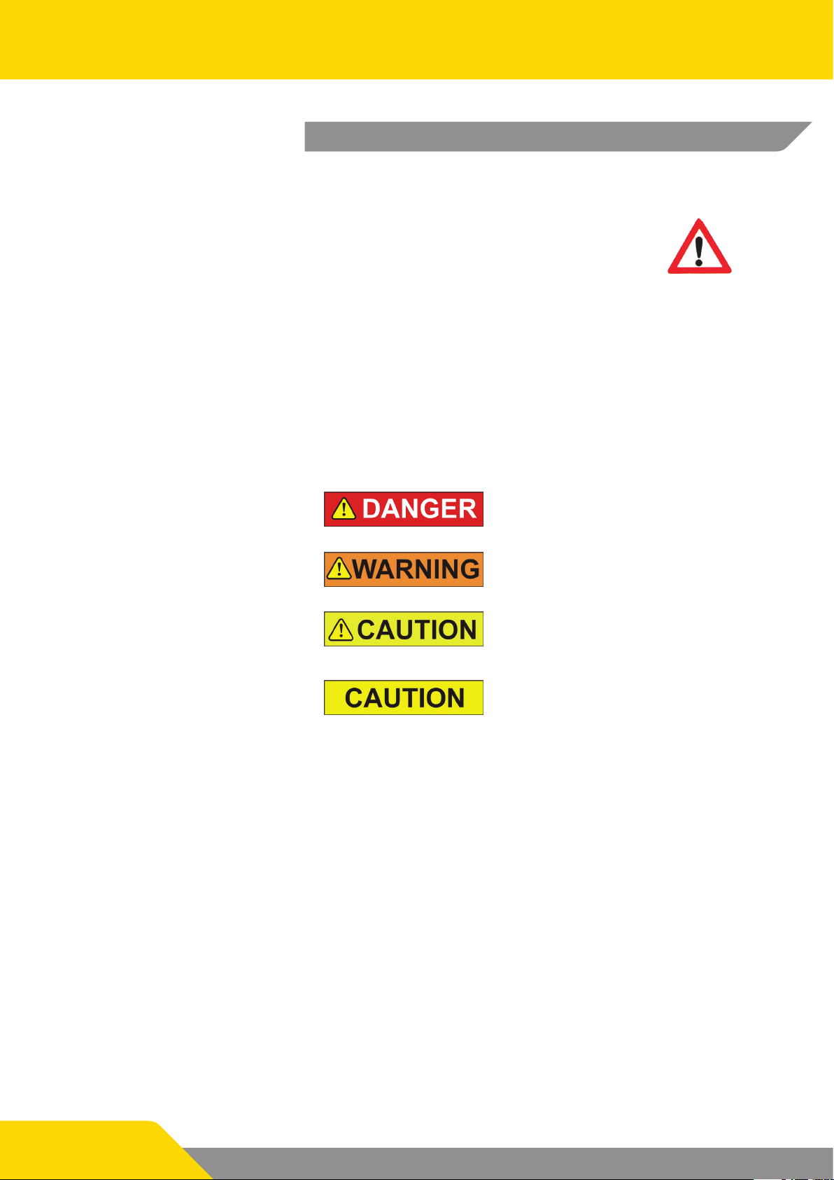
1.1 Symbols used
This symbol means that there is imminent danger. If it is not avoided then death or serious injury will result.
This symbol means that there is a possible dangerous situation. If it is not avoided then death or
serious injury could result.
This symbol means that there is possibly a dangerous situation. If it is not avoided then light injuries or slight injuries could result.
This symbol means that there is the possibility of
damage being caused. If it is not avoided then
the product or something else in its vicinity could
be damaged.
Page 4/39

1.2 Correct handling and usage
Depending on the application, Vetter leak sealers must only be
used with compressed air and only inated to the corresponding
pressure with original ination ttings.
They are exclusively used for sealing leaks on containers and
pipes.
Incorrect application of Vetter leak sealers includes the following:
9 Incorrect use, operation or maintenance of leak sealers.
9 Use of the leak sealers with defective safety devices or inati-
on ttings which have been either incorrectly installed or are
non-functional.
9 Non-observance of the instructions contained in the opera-
ting instructions with respect to storage, operation and maintenance of the leak sealers.
9 Insucient monitoring of accessory parts which are subject
to wear.
9 Incorrectly carried out maintenance work.
The following also belong to correct application:
9 Observance of all information contained in these operating
instructions.
9 Compliance to the periods for maintenance and care contai-
ned in the Chapter “Maintenance and Care”.
2. Safety instructions
The use of Vetter Leak Sealers is made under the precondition that
there is a knowledge of this application and that the operating
instructions are observed.
2.1 General information
The observance of all pertinent regulations with respect to work
protection, safety and accident prevention (e.g. GUV) as well as
generally recognized technological regulations is a precondition.
Leak sealers must be tested before application to see whether
they are resistant against hazardous materials. For this, refer to the
resistance chart!
The PVC acid protection cover for the leak sealing bag oers increased protection against acid spray.
Observe the pertinent regulations concerning handling with dangerous liquids.
Protection equipment, such as protection clothing, gloves, helmet, face and eye protection, breathing protection and inherent
protection, are to be used onsite depending on the degree of
danger and the situation.
Page 5/39
Vetter Leak Sealers
2.2 Information concerning the dangers
Danger of explosion! If there are inammable liquid or gas leaks it
is imperative that sparks be avoided by xtures and ttings.
Vetter Leak Sealers must only be lled when in the correctly tensioned condition. Only ll the leak sealers until the leak is sealed
(max. operating pressure 1.5 bar and 10 bar). Any additional lling
of the leak sealer can damage the pipe or the tank by built up
pressures
A leak in a tank or container is a weak point. Therefore avoid any
additional damage by lling the leak sealer so that no more liquid
or gas escapes. This can be the case at a point lower than the maximum permissible operating pressure.
2.3 Warning information
The leak sealers and the accessories are to be inspected for perfect condition before and after use. Damaged seals or seals and
accessories which are functionally limited present a source of danger and must not be used!
All controllers are equipped with a safety valve that corresponds
to the maximum permitted operation pressure for leak sealers.
These safety valves will blow when the maximum operating pressure is exceeded.
The tolerance for the opening and closing of the safety valves
must be a maximum of + 10%. The set pressure must not be changed. Should the seal on the upper part of the valve be removed
then safe operation can no longer be guaranteed. The safety valve
must be exchanged. The permitted input pressure at the controller must not be exceeded (marked on the input coupling).
Before application of the leak sealer, cover sharp edges and/or
pointed positions in the area of the leak by using dimensioned
sealing plates. In doing this you avoid damage to the leak sealers
as well as the unintended escape of dangerous liquids and gases.
Page 6/39
3. Operation of the Leak Sealers
This chapter gives you information about which sources of compressed air you are able to use with Vetter leak sealers.
When using leak sealers observe the
corresponding pressure stage.
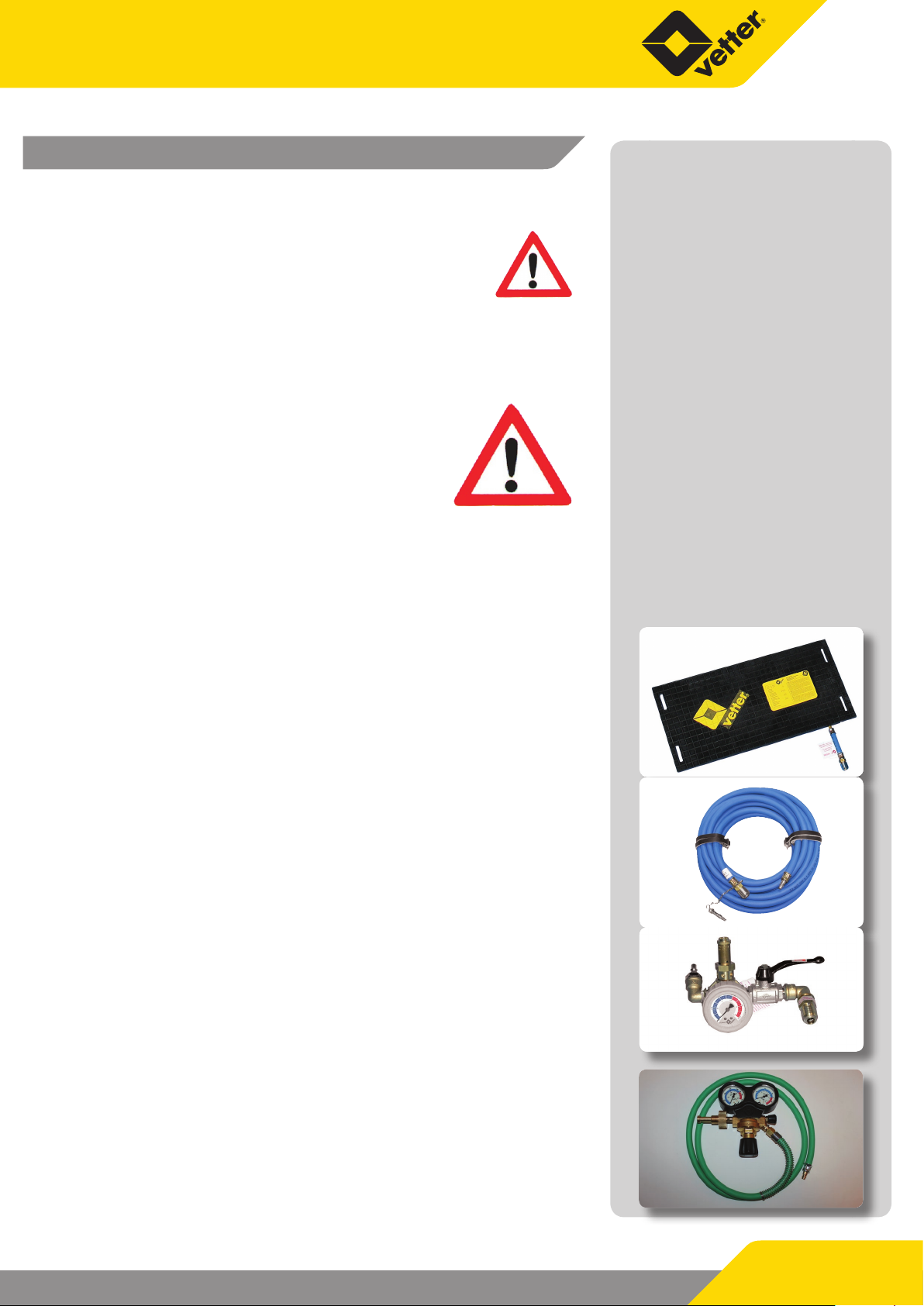
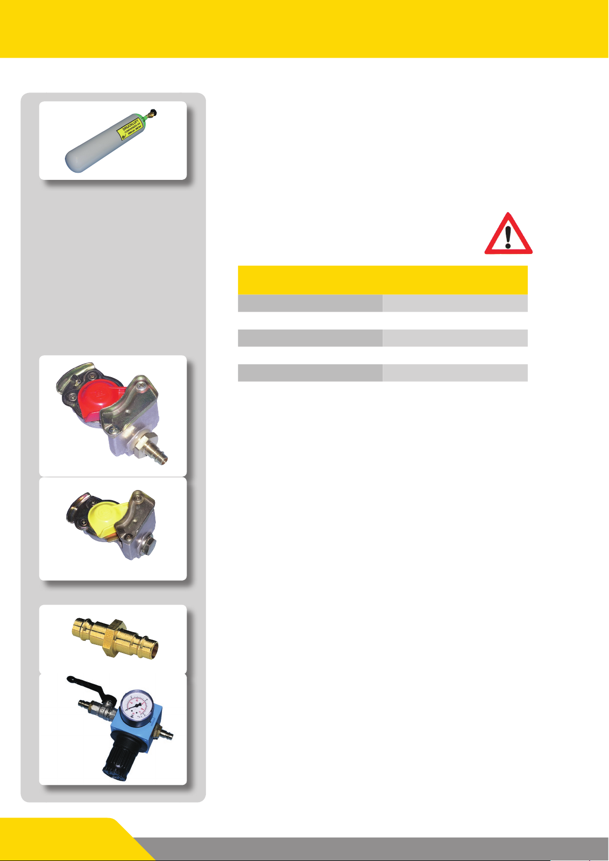
3.1 Operation with controllers, ination hose and
compressed air bottle
As an example the following pictures present
the sequence of events for leak sealing
bags 1.5 bar. Corresponding leak sealers
and accessories must be used for other
pressures and other sources of air.
Before ination, the leak sealing bags
must be correctly and safely tensioned
with tension belts on the leak position.
To do this, refer to Chapter 4.3 “Handling the tension ratchet”.
Leak sealing bag
9 Step 1
Connect the leak sealing bag LD 50/30 S 1.5 bar with guide
slots to the ination hose.
Ination hose
9 Step 2
Connect the ination hose to the controller.
Controller
9 Step 3
Connect the connection hose of the pressure regulator to
the input coupling of the controller. It is imperative that the
permitted input pressure of the controller be observed when
doing this.
Pressure regulator
9 Step 4
Screw the pressure regulator into the valve on the compressed
air bottle.
Page 7/39
Vetter Leak Sealers
Compressed air bottle
3.2 Operation of the controller, ination hose and
other sources of compressed air
Observe the maximum input pressures of the
controllers for the various pressures
(refer to the table below).
Truck compressed
air connection
Blind coupling
Applied pressure
0.5 bar 2 bar
1.0 bar 2 bar
1.5 bar 2 bar
2.5 bar 4 bar
10.0 bar 10 bar
Maximum input pressure of
the controller
Adapters contained in the adapter kit
The adapter kit contains adapters for the following sources of
compressed air:
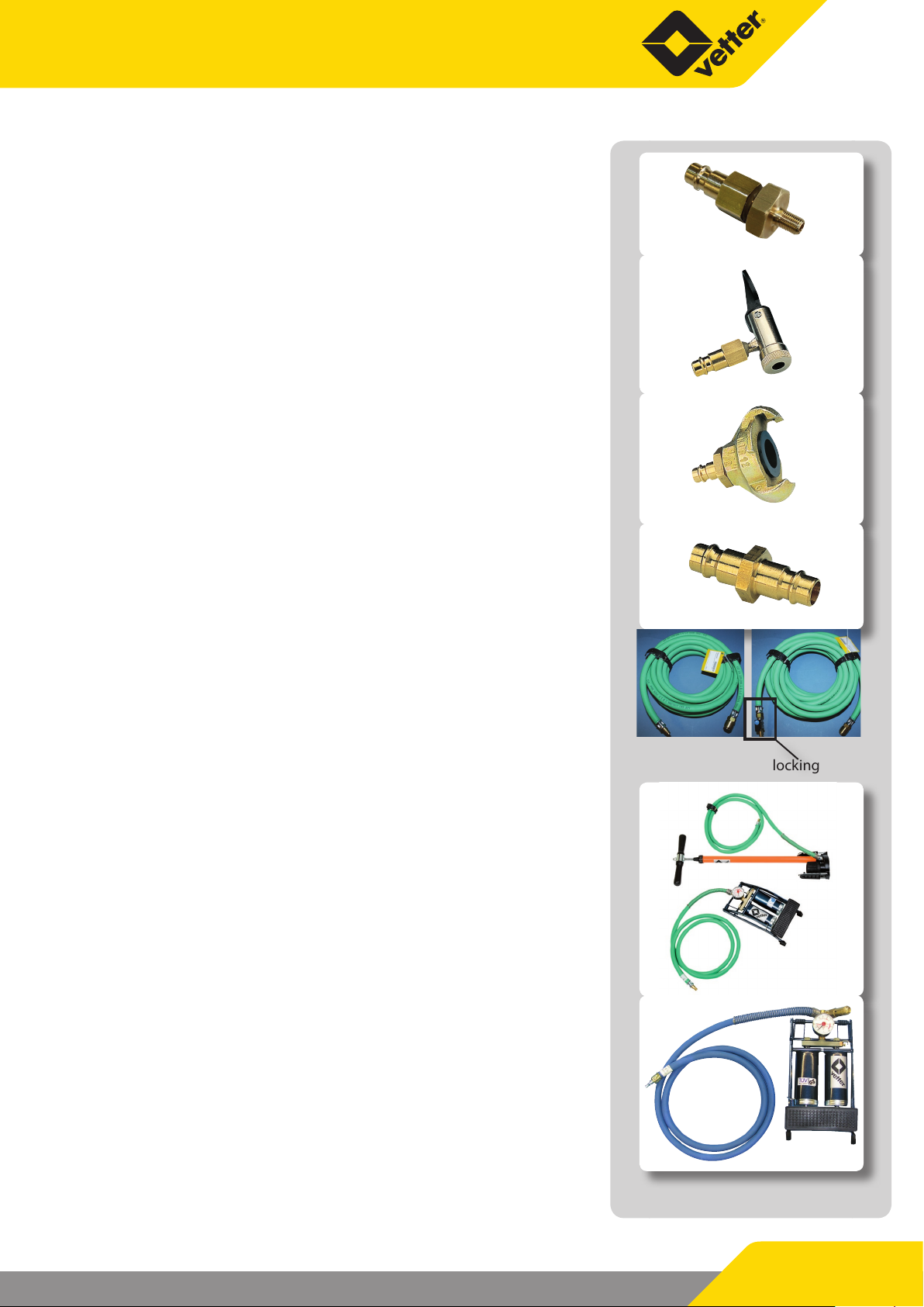
Truck compressed air connection with blind coupling
Close the control line to the blind coupling.
The tyre ination connection must be secured with a safety valve
as a standard.
The control line is to be connected with the blind coupling. The
truck must be secured by brake holding blocks so that it does not
roll away.
Page 8/39
Local compressed air network
Connection to the outlet coupling of a compressed air network.
Series connected pressure regulator, max input pressure
of 16 bar
If the output pressure of the compressed air network exceeds the
permitted ination pressure of the controller then the adapter
must be exchanged for a series connected pressure regulator.
Truck tyre valve
Used for inating with a normal hand pump or foot pump.
Truck tyre valve connection
For tapping o air from the spare tyre.
Adapter for construction site compressor
Adapter for portable compressor
Air supply hose, 10 m, with and without blocking valve
The air supply hoses with or without blocking valve can be used
as an extension between air source and the controller.
3.3 Operation with hand pump and foot air pump
Hand pump or foot pump for connection to the input coupling of
a controller via a 2 m connection hose.
3.4 Operation with foot air pump having safety
valve and manometer
Foot air pump 1.5 bar with safety valve and manometer and 2 m
connection hose for ination of leak sealing bags.
Blocking valve
Page 9/39
Vetter Leak Sealers
4. Application of Leak Sealers
This chapter gives you information about how Vetter leak sealers
are used.
When using leak sealers, observe the safety
instructions in Chapter 2 as well as the pertinent regulations for work protection and
safety, accident prevention regulations
(e.g. GUV) and the general rules for technology.
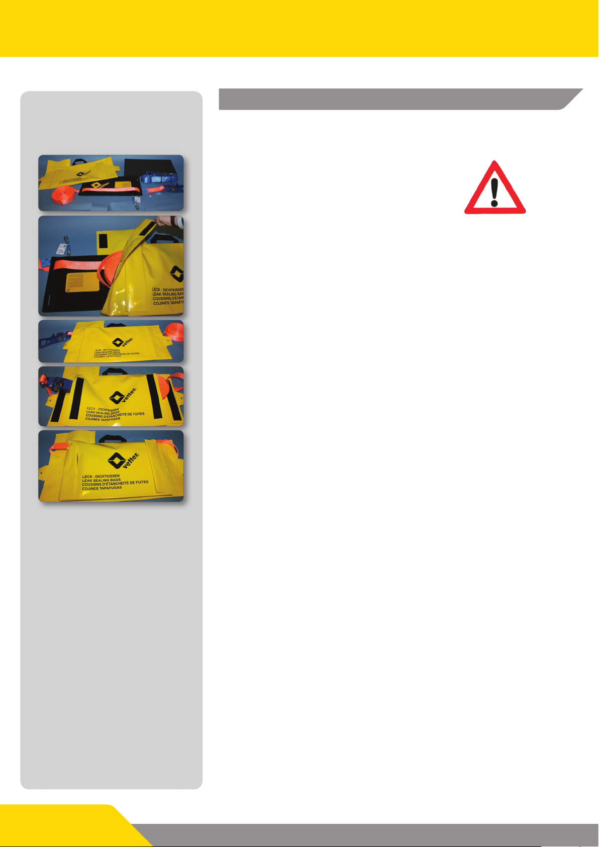
4.1 Use of the acid protection covering
The special design of the acid protection covering permits storing
the ready-for-use leak sealing bag including the tension belts on
the emergency vehicle.
The simplied illustrations show
only one tension belt!
9 Route both tension belts through the belt bushing slots or
the swivel eyes.
9 The bag is stored in the acid protection covering, possibly
with an upholstery plate underneath, and secured with a Velcro fastener. Please note that the valve connection should lie
in the ap!
9 The tension belts are accommodated in the upper Velcro-fas-
tener pocket.
4.2 Preparing for operation
Wear the required protective gear and clothing suitable for the
task.
9 Select and put on the personal protective equipment corres-
ponding to the degree of danger.
9 Mark the work area.
9 Ensure that only authorized persons are in the work area /
area of danger.
9 Select the leak sealing bag/leak sealer according to the requi-
rements.
Page 10/39
9 In doing this observe the resistance chart and material resis-
tance chart.
9 Check the leak sealing bag/the leak sealer and the accessories
to be used for completeness and for any forms of damage.
9 Damaged leak sealing bags/leak sealers and accessories must
not be used!
9 Ination hose and controller must already be connected to
the leak sealing bag/leak sealer.
9 Place the tension belts around the tank/container.
9 Loosely close the leak position with the sealing bag / leak sea-
ler.
9 Tension the leak sealer with the tension belts.
9 Make certain that there is nobody within the area of danger.
9 Inate the leak sealer from a safe position until the leak is
sealed.
Danger of explosion! If there are inammable liquid or gas leaks it
is imperative that sparks be avoided by xtures and ttings.
Vetter sealing must only be lled when in the correctly tensioned
condition. Only ll the leak sealing until the leak is sealed (max.
operating pressure 1.5 bar and 10 bar). Any additional lling of
the leak sealer can damage the pipe or the tank by built up pressures.
A leak in a container or pipe is a weak point. Therefore avoid any
additional damage by lling the leak sealer so that no more liquid
or gas escapes. This can be the case at a point lower than the maximum permissible operating pressure.
Before application of the leak sealer, cover sharp edges and/or
pointed positions in the area of the leak by using dimensioned
sealing plates. In doing this you avoid damage to the leak sealers
as well as unintended escape of dangerous liquids and gases.
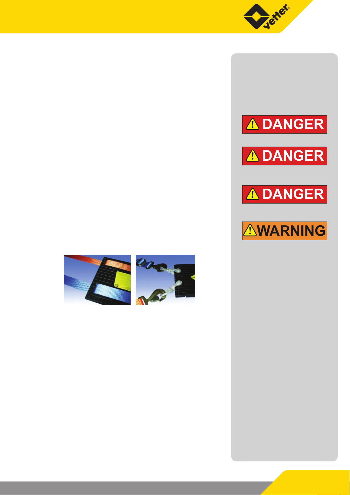
The Vetter Leak Sealing Bags LD 50/30 come in two dierent versions each having dierent tensioning possibilities available.
Leak sealing bags with
guide slots
Leak sealing bags with
rotating lugs
Page 11/39
Vetter Leak Sealers
2
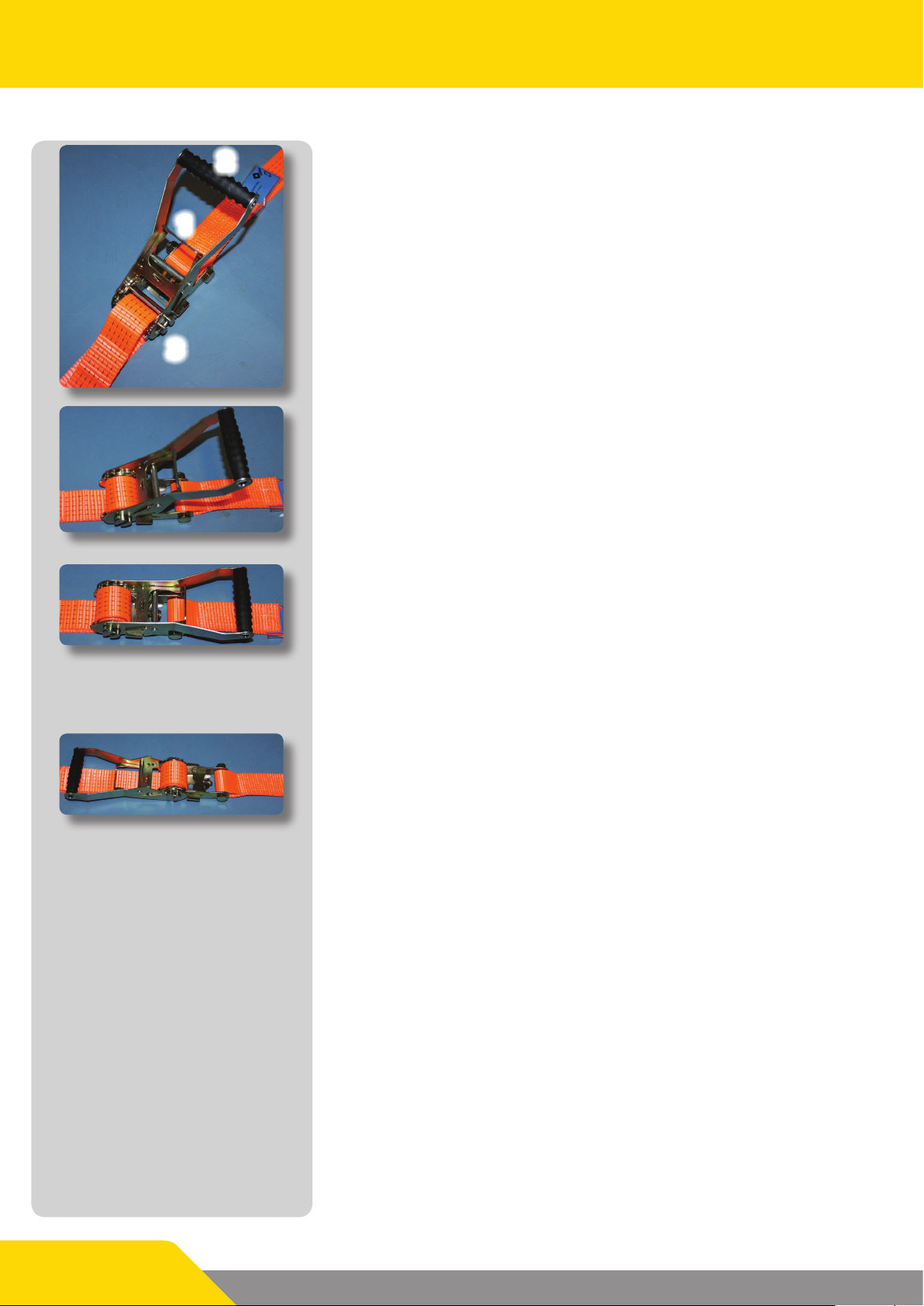
4.3 Handling the tension ratchet
Threading the belt
1
With the ratchet closed, quickly pull the locked function slide (1)
in order to move the ratchet lever (2). Thread the end of the belt
into an appropriate position in the slot shaft (3) and pull until the
belt is tensioned.
3
Tensioning the belt
By moving the ratchet lever, ratchet until the required, or maximum, belt tension is obtained. In doing this there must be at least
1.5 turns on the slot shaft.
Closing the ratchet
After this, pull the function slid and swing the ratchet lever into
the locking position until the slid is able to lock into the securing
groove.
Opening the ratchet
Before opening the ratchet it is imperative to ensure that the leak
sealing bag is not under pressure because when opening the ratchet, the belt is suddenly released.
When opening the ratchet, the function slid is to be pulled and
the ratchet lever is to be swung approximately 180° to the end
stop in order to let the slide lock into the last possible position.
The slot shaft is now no longer locked. The belt can now be uncoiled and taken out.
Page 12/39
 Loading...