

Page 1

6/11/2012 RSH-series manual, installation instructions.doc
INSTALLATION MANUAL: RSH-SERIES
RUBBER SPEED HUMP & ANCHOR KIT
VESTIL MANUFACTURING CORP.
2999 NORTH WAYNE STREET
P.O. BOX 507, ANGOLA, IN 46703
TELEPHONE: (260) 665-7586 -OR- TOLL FREE (800) 348-0868
FAX: (260) 665-1339
URL: WWW.VESTILMFG.COM EMAIL: SALES@VESTIL.COM
NOTE: Compliance with regulations, codes, and/or statutory (non-voluntary) standards enforced in the
location where the traffic control device is installed is exclusively the responsibility of the end-user.
Table of Contents Table of Figures
Product Introduction………………………... 2 FIG. 1 “Assemble the speed hump”…………… ……….… 3
Safety Principles……………………............. 2 FIG. 2 “Hardware kits”………………………………………. 3
Installation Instructions………….…............ 3 - 4 FIG. 3 “Attach product the asphalt surface”………………. 3
Inspections & Maintenance………………… 4 FIG. 4 “Attach product to concrete surface”……………… 4
Cop
yright 2010 Vestil Manufacturing Corp.
1 of 4
Page 2
6/11/2012 RSH-series manual, installation instructions.doc
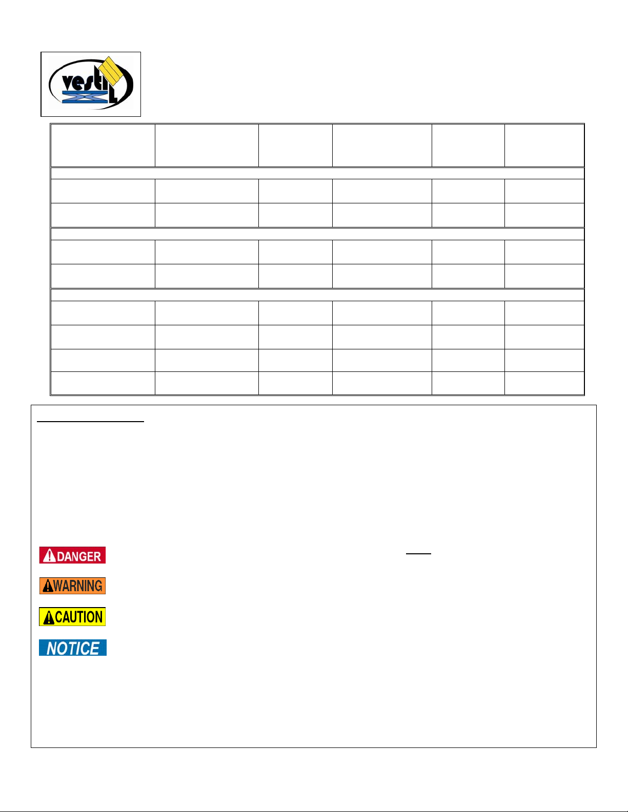
PRODUCT INTRODUCTION
Model
“Mini” rubber speed humps
RSMH-18C-GRN
RSMH-18E-GRN
Thank you for purchasing an RSH-series rubber speed hump, referred to in this manual as
“sp
eed hump,” “traffic control device [TCD]” or “the product”. Our speed humps are durable,
high-quality products rigorously engineered for dependability and simplicity. Although installation
and maintenance procedures are intuitively obvious, any person who might install or maintain
this product should be familiar with the instructions provided in this manual.
Dimensions and other product specifications appear in the following table:
Overall dimensions
(W x L x H) in inches
(~cm)
18 x 24 x 2¼
(45.7 x 61 x 5.7)cm
18 x 24 x 2¼
(45.7 x 61 x 5.7)cm
Description
Center section
End section
Includes kit of
hardware to anchor
hump to concrete
or asphalt
Both kits
Both kits
Maximum
over-travel
speed in MPH
(~kph)
15
(25kph)
15
(25kph)
Net weight in
pounds (~kg)
28
(12.7kg
28
(12.7kg)
Medium rubber speed bumps
RSH-36C-GRN
RSH-36E-GRN
36 x 24 x 2½
91.4 x 61 x 5.7)
36 x 24 x 2½
91.4 x 61 x 5.7)
Center section
End section
Both kits
Both kits
20
(33kph)
20
(33kph)
53
(24.1kg)
53
(24.1kg)
Deluxe rubber speed humps
RSH-108-24-C
RSH-108-24-A
RSH-120-36-C
RSH-120-36-A
24 x 108 x 1.2
~(61 x 274.3 x 3)cm
24 x 108 x 1.2
~(61 x 274.3 x 3)cm
36 x 120 x 2
~(91.4 x 305 x 5.1)cm
36 x 120 x 2
~(91.4 x 305 x 5.1)cm
Complete
assembly
Complete
assembly
Complete
assembly
Complete
assembly
Concrete
Asphalt
Concrete
Asphalt
5 - 10
(8 – 17kph)
5 - 10
(8 – 17kph)
5 - 10
(8 – 17kph)
5 - 10
(8 – 17kph)
106
(48.2kg)
113
(51.4kg)
256
(116.4kg)
264
(120kg)
Safety Principles
Vestil Manufacturing Corp. recognizes the critical importance of workplace safety. However, although Vestil diligently
strives to identify foreseeable hazardous situations, this manual cannot address every conceivable danger. The end-user
is ultimately responsible for exercising sound judgment at all times.
This manual will acquaint persons authorized to install and/or maintain this speed hump with proper installation and
maintenance procedures. Therefore, each person, who might use or perform maintenance on the speed hump,
must read and understand every instruction BEFORE using the device or performing maintenance. Users should
have access to the manual at all times and should routinely review the directions.
This manual uses SIGNAL WORDS to classify personal injury risks and situations that might lead to property damage,
as well as to draw attention to safety message(s). The reader must understand that each signal word indicates the
seriousness of the identified hazard.
Identifies a hazardous situation which, if not avoided, WILL result in DEATH or SERIOUS
Identifies a hazardous situation which, if not avoided, COULD result in DEATH or SERIOUS
Indicates a hazardous situation which, if not avoided, COULD result in MINOR or MODERATE
Identifies practices likely to result in product/property damage, such as operation that might damage the
Employers are responsible for training employees to use the product properly. If you do not understand an instruction,
ask your supervisor or employer for assistance, because failure to follow the directions in this manual might result in
serious personal injury or even death.
Vestil is not liable for any injury or property damage that occurs as a consequence of failing to apply either: 1) the
instructions that appear in this manual; or if applicable 2) the information provided on labels affixed to the product.
Furthermore, failure to exercise good judgment and common sense might result in property damage, serious personal
injury or death. Such failure is solely the fault of the person(s) using the speed hump.
INJURY. Use of this signal word is limited to the most extreme situations.
INJURY.
injury.
speed hump.
Cop
yright 2010 Vestil Manufacturing Corp.
2 of 4
Page 3

6/11/2012 RSH-series manual, installation instructions.doc
Failure to read and understand the instructions included in this manual before installing or maintaining the
speed hump constitutes misuse of the product. Read the manual, as necessary, to refresh your understanding of the
safe installation, inspection and maintenance procedures explained on p. 3 & 4. DO NOT attempt to resolve any problems
with the product unless you are authorized to do so and are certain
that it will be safe to use afterwards.
Improper installation might result in serious personal injuries sustained by motorists and/or pedestrians.
Immediately replace any speed hump that becomes structurally compromised. DO NOT keep a damaged speed hump
in service. Follow the inspection recommendations presented on p. 4 to determine whether a speed hump or a portion
of the product should be replaced.
Post signs visible to and readable by motorists to warn them about the location of the speed hump and to suggest an
appropriate maximum speed when travelling over the hump (see “Maximum over-travel speed” in Ta ble on p. 2).
DO NOT modify the speed hump or the mounting hardware in any way. Unauthorized modifications might make the
product unsafe to use and could result in injuries suffered by drivers and/or bystanders.
Installation
FIG. 1: Assemble the speed hump FIG. 2: Hardware Kits
Step 1
hump will be installed. Thoroughly sweep the surface/road
and allow the surface to dry completely, if applicable.
Step 2
will be installed. Fit the tabs of one piece into the
corresponding slots on the next piece, as shown in FIG. 3.
[NOTE: 1 end piece has tabs; the other end piece has
slots.]
Step 3
: Prepare the surface (road) where the speed
: Assemble the speed hump in the location where it
: Attach the speed hump to the surface.
Asphalt: to attach the product to an asphalt surface:
1) As shown in Fig. 3, affix strips of butyl tape to the entire
perimeter of the underside of the speed hump (only 1 side of
perimeter shown in Fig. 3, but tape should be applied to all 4
sides);
2) Flip over the speed hump and then press it firmly against the
pavement;
3) Drive the spikes through the holes in each section (the head
of each spike should not protrude above the surface of the
speed hump).
11-7/8in.
: Attach product to asphalt surface
FIG. 3
Butyl
tape
Lag bolt
Flat
wash
Anc
sleeve
Asphalt
spike
Asphalt
er
hor
Cop
yright 2010 Vestil Manufacturing Corp.
3 of 4
Page 4

6/11/2012 RSH-series manual, installation instructions.doc
Concrete
1) Mark the concrete with the location of each bolt hole;
:
FIG. 4: Attach product to concrete surface
Lag bolt
2) Drill 13/16in. (~2.1cm) holes in the concrete approximately 6in.
deep (locations shown as X’s in the diagram above);
3) Press/tap the anchor sleeves into the drilled holes until they
are at least flush with the road surface or slightly lower.
4) Align the holes in the speed hump with the holes drilled into
the concrete surface. Slide a washer onto each lag bolt; then
insert a bolt into each bolt hole and tightly fasten the bolts to the
anchors.
Concrete
Inspections & Maintenance
At least once per month:
Closely inspect each section of the speed hump for damage (cracks, splits, etc.). If any section is cracked or split,
replace it.
Try to wiggle the sections of the speed hump to evaluate the soundness of the connections between anchor bolts and
anchors, as well as between the anchors and the road/surface. If the speed hump can wobble, i.e. separates from the
road/surface, determine whether each connection is loose. Tighten loose connection(s) and apply more butyl tape to the
bottom of the loose section. It might be necessary to either fill a hole(s) in the concrete with epoxy or move the speed
hump to another location, if the bolt and anchor can slide free of the concrete.
The speed hump incorporates yellow highway tape to provide a sharp contrast with the surface/road. Wipe dirt and
other filth from the surface of the speed hump, and particularly from the highway tape to maintain contrast.
Copyright 2010 Vestil Manufacturing Corp.
4 of 4
 Loading...