

Page 1
VESTIL MANUFACTURING CORPORATION
P.O. Box 507., Angola, IN 46703 USA
Phone (260) 665-7586 • Fax (260) 665-1339
E-mail: sales@vestil.com • www.vestil.com
Loading Dock Equipment
Revised 04-06
A company dedicated to solving ergonomic and material
handling problems since 1955
.
OWNER'S
MANUAL
RR-Series Mechanical Docklevelers
Contents
Warnings & Safety Instructions ....................... 1
Replacement Parts .......................................... 1
Receiving Instructions ..................................... 1
WARNINGS & SAFETY INSTRUCTIONS
Ensure that all employees understand and follow the
following.
• When working on the dockleveler, barricade it off to
traffic from on the dock and on the approach.
• Always brace leveler securely in the “UP” position
when performing maintenance work.
• Always brace lip in extended position when working on
lip or leveler.
• Check toe guards to ensure they are functional.
• When testing dockleveler be certain everyone is clear
from the swinging lip.
• When operating leveler, do not walk on lip.
• Return dockleveler to level, supported position after
maintenance or use is completed.
• Do not leave any cargo or equipment on deck of
dockleveler.
• Do not drive a fork truck or other material handling
equipment on dockleveler to bring deck down to the
truck bed.
• Monthly visual inspection of the dockleveler shall be
made to verify that there are no missing or damaged
components including toe guards.
WHEN ORDERING REPLACEMENT PARTS
We take pride in using quality parts on the equipment we
manufacture. We are not responsible for equipment
problems resulting from the use of unapproved
replacement parts.
To order replacement or spare parts for this equipment,
contact the factory.
In any communication with the factory please be
prepared to provide the machine’s serial number, which is
indicated on the machine dataplate.
Warranty ........................................................... 1
Operation Instructions ...................................... 2
Adjusting Instructions ....................................... 3
Parts List ............................................................. 4
RECEIVING INSTRUCTIONS
Every unit is thoroughly tested and inspected prior to
shipment. However, it is possible that the unit could incur
damage during transit.
Inspect the unit closely when it arrives.
evidence of damage or rough handling to either the
packaging or to the product when it is being unloaded,
immediately make a note of it on the Bill Of Lading!
It is important that you remove the product’s packaging
upon its arrival to ensure that there is no concealed
damage or to enable a timely claim with the carrier for
freight damage.
Also verify that the product and its specifications are as
ordered.
If you see
LIMITED WARRANTY
We warrant that this dockleveler is to be free from
defects for one (1) year from date of shipment.
We will bear the cost of repairing or replacing, at our
option, any defect. We will issue a Return Goods
Authorization Number for a return or a Purchase Order
Number for a repair. We do not cover costs for jobsite
labor, loss of use, or any consequential damages. To be
covered by our warranty, equipment must be installed and
maintained in accordance with the guidelines of this
manual and operated within the rated capacity. Periodic
lubrication and adjustment are the responsibility of the
owner.
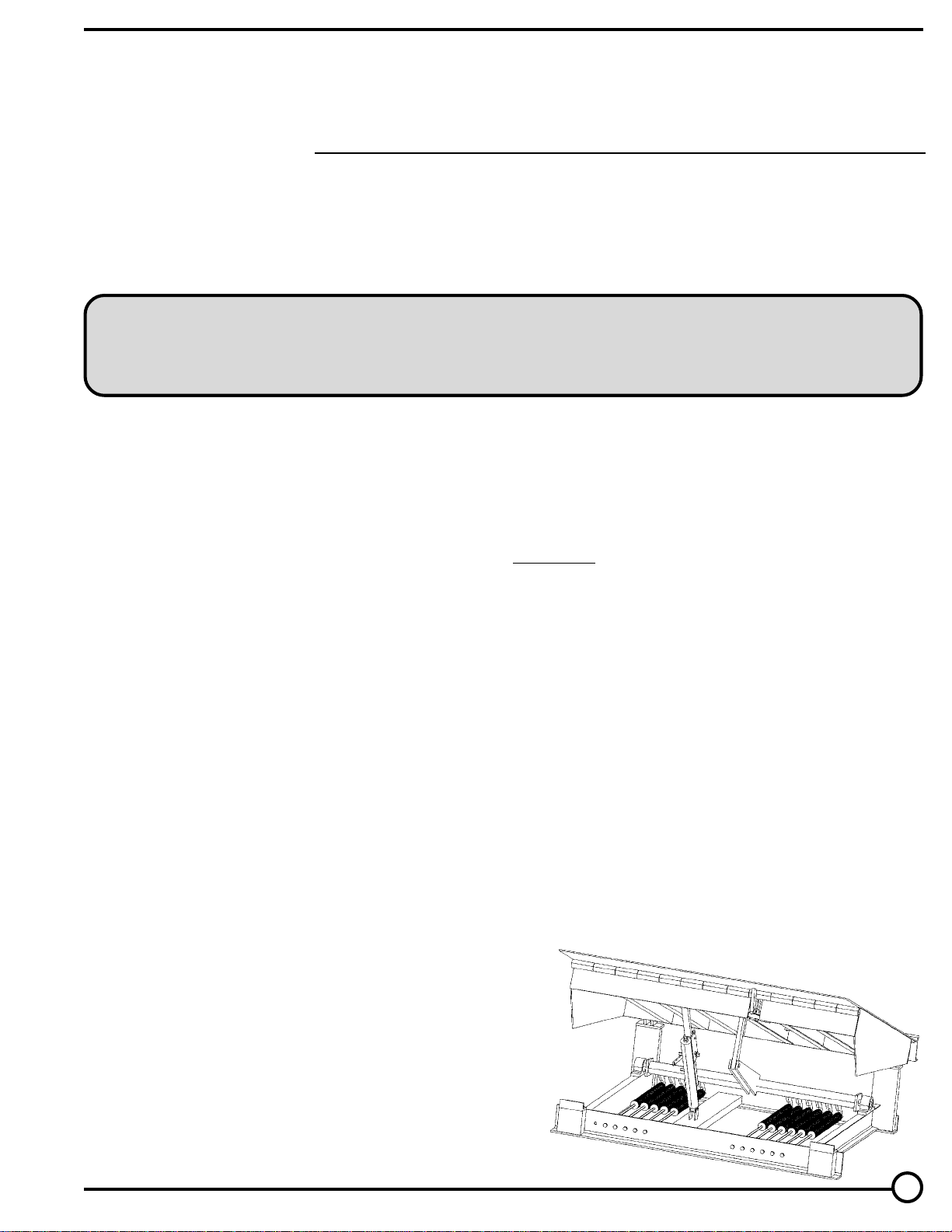
RR-Series
Mechanical Dockleveler
1
Page 2

OPERATING INSTRUCTIONS
• After truck is spotted against bumpers the dockleveler user chocks the truck wheels on both
sides.
• The user now looks at the cargo area of the truck to see if there is ample room for the
dockleveler lip to go onto the trailer.
• The lip will require about twelve inches (12”) beyond the bumper for the standard sixteen inch
(16”) lip.
• If there is not sufficient clear distance to put the lip, the area needs to be cleared manually or
with a fork truck. Before a fork truck is driven on the dockleveler deck the user should verify the
lip is in the vertical position securely behind the lip keepers. If the deck is below dock height the
user brings the dockleveler up above the dock floor by releasing the deck using the pull in the
rear center of the deck. Release pull as soon as deck is a few inches above floor height then
walk on deck to bring it back to the level supported position.
• After the lip contact area is clear the user goes to the rear of the deck and pulls the release after
verifying that no one will be hit by the raising deck and the extending lip. The deck comes up
and the lip extends automatically. The user releases the pull and promptly walks on the deck
which brings it down until the lip is on the truck bed. (DO NOT WALK ON LIP). Loading/
unloading may now commence.
• If the dockleveler is equipped with optional safety legs they need to be retracted if the trailer is
below floor height. Retract safety legs by pulling ring at rear of leveler. Release safety legs
immediately after lip comes to rest on trailer. Do not leave any cargo or equipment on the
dockleveler deck at any time.
• When loading/unloading is complete the dockleveler can be taken out of the truck by pulling the
recessed handle releasing the deck until the lip clears the truck. Wait for the lip to completely
retract and then walk on the deck until it comes back to the floor height. Check to be sure the
lip is behind the keepers. The overhead door of a trailer and/or the building may now be closed
and the wheel chocks removed.
• If the truck departs prior to removing the lip from the trailer the lip will fall to the down position.
The lip may or may not be in the keepers. The user must release the deck to a few inches above
floor height, allow the lip to fully retract and walk on the deck to bring the lip down to rest behind
the keepers. Visual inspection is necessary.
2
Page 3

ADJUSTING INSTRUCTIONS
(Review Safety Precautions before doing any work.)
The key to long term, dependable use of your dockleveler is proper maintenance.
Prior to doing adjustments on your dockleveler you need to grease and oil the friction points plus
clean all debris from leveler.
Cleaning is the first step. Remove all debris from the pit. Clean the lip hinge and the lip operating
mechanism. Wipe dirt and/or material from ratchet mechanism including the ratchet and paw. Clean
deck hinge.
Zerk fittings to be greased (lithium base preferred) as follows:
1. Lip hinge
2. Pillow block at ends of trunion
3. Rotating cam in center of dockleveler deck
4. If unit is equipped with safety stops grease both sides
Oil all moving parts liberally. The only exception is the ratchet bar and the locking paw which should
not be oiled. Use a grafite base oil. Oiling is required every thirty (30) days. Oil hooking point at the
end of the springs.
There are two primary adjustments required on your dockleveler as follows:
Lip Extending Mechanism
The lip is extended by the lip cable and the lip counterbalance spring. The function sequence should
be as follows: The deck comes up making the lip cable taught pulling the lip out with the assistance of
the counterbalance spring. The lip is momentarily held in the extended position by the two hydraulic
dampers.
It is important to know how much tension to put on the lip assist spring. You want the maximum force
you can get and still have the lip fall back to the vertical position.
Repeat the following sequence until the lip doesn’t fall back to the vertical position. Grab the lip end
and manually extend lip. Release the lip. If it falls to the vertical position tighten spring nut clockwise.
When lip doesn’t come down to vertical position you have went too far and you need to back off the
nut slightly.
Deck Raising Mechanism
It is important to know how much counterbalance force you need to achieve proper operation.
When making your counterbalancing adjustments, take up on all springs approximately the same
amount.
Your deck needs to come up with enough speed to provide the momentum to extend the lip as
previously outlined. If the lip doesn’t extend when the deck comes up you need more
counterbalancing force. Back off on counterbalance springs by turning the bolts counter clockwise.
Other causes of malfunction are as follows:
1. Platform hitting sides of pit
2. Bent ratchet bar
3. Worn ratchet or paw teeth
4. Broken activating cable
3
Page 4

PARTS LIST
6
11
12
13
14
15
ITEM NO.
1
2
3
4
5
6
7
8
N/S
9
10
11
12
13
14
15
17
18
19
20
21
22
N/S
N/S
N/S
N/S
N/S
N/S
N/S
N/S
1
19
PART NUMBER
D-COMP
D-TR
D-TRPB
D-CBS
D-CBSB-**
D-URP
D-LRP
D-REL-CH
D-REL-RF-KIT
D-UTLP
D-LTLP
D-UPLP
D-CY
D-W
D-TPIN
D-CTP
D-TC
D-SS
D-BPIN
D-LR
D-LS
D-LAM
HNG-CST
DM2-6-HP
DM2-7-HP
D-LAM-LP
DM2-**-**-20,000LA
DM2-**-**-50,000LA
DM2-**-TTG
D-ES-SPG
20
17
2
3
10
4
18
21
5
22
7
8
DESCRIPTION
Ratchet Hold Down Assembly (38 lbs.)
Trunion
Trunion Pillow Block Bearings
Counter Balance Springs
Spring Bolt (must have dock model #)
Upper Ratchet Pin
Lower Ratchet Pin
Release Chain
Release Chain Retrofit Kit with Rollers
Upper Trunion Link Pin
Lower Trunion Link Pin
Upper Link Pin (lip kick mech.)
Lip Cylinder (shock absorbers)
Washer
Top Cylinder Pin
Cotter Pin
Lip Trip Cable with Spring
Spring Shackle
Bottom Cylinder Pin
Lip Rod
Lip Spring
Complete Lip Actuating Mechanism
Hinge Block (Casting Weldment)
Hinge Pin for 6’ Wide Leveler
Hinge Pin for 7’ Wide Leveler
Lip Post for Actuating Mech.
Lip Assembly (Must have length + width)
Lip Assembly (Must have length + width)
Telescopic Toe Guard (Must have model number)
Emergency Stop Return Spring
9
4
Page 5

 Loading...