

Page 1
VESTIL MANUFACTURING CORPORATION
2999 North Wayne St., Angola, IN 46703 USA
Phone (260) 665-9521 • Fax (260) 665-1339
E-mail: sales@vestil.com • www.vestil.com
Ergonomic Solutions
Contents
Warning and Safety Instructions ..................... 1
Receiving Instructions ...................................... 1
Installation Instructions - EHLT & PST ....................2
Operating Instructions - EHLT ................................. 3
Instructions for Battery Unit - PST ..........................4
Maintenance & Safety Checks - EHLT & PST.......5
Power Units Operation - EHLT & PST .....................6
Motor & Transformer Connection - EHLT & PST . 7
WARNINGS & SAFETY INSTRUCTIONS
Ensure that all employees understand and follow the
following instructions.
• Read and understand the owner's manual before using or
serving the lift.
• The load must be removed from the platform and the
maintenance props installed before any work is performed
on the lift.
• For battery-powered units, review the additional warnings
included elsewhere in this manual.
• Ensure that all safety and warning labels stay in place and
are legible. See the labels page in this manual.
• For non-portable units, the scissor lift frame must be
securely anchored to the floor. See the installation
instructions.
• Do not use the lift if any damage or unusual noise is
observed.
• Always watch the lift and any load on it carefully when it is
in operation.
• The platform's load must be centered and evenly
distributed on the platform.
• Do not perform any modifications to the lift without the
manufacturer's approval. Failure to receive authorization
for changes to the equipment could void the warranty.
• Maintenance and repair are to be done only by personnel
qualified to perform the required work.
• Do not use brake fluid or jack oils in the hydraulic system.
If oil is needed, use an anti-wear hydraulic oil with a
viscosity grade of 150 SUS at 100°F, (ISO 32 @ 40°C), or
Dexron transmission fluid.
• Use only replacement parts either supplied or approved
by the manufacturer.
Revised 09-03
A company dedicated to solving ergonomic and material
handling problems since 1955
.
OWNERS
MANUAL
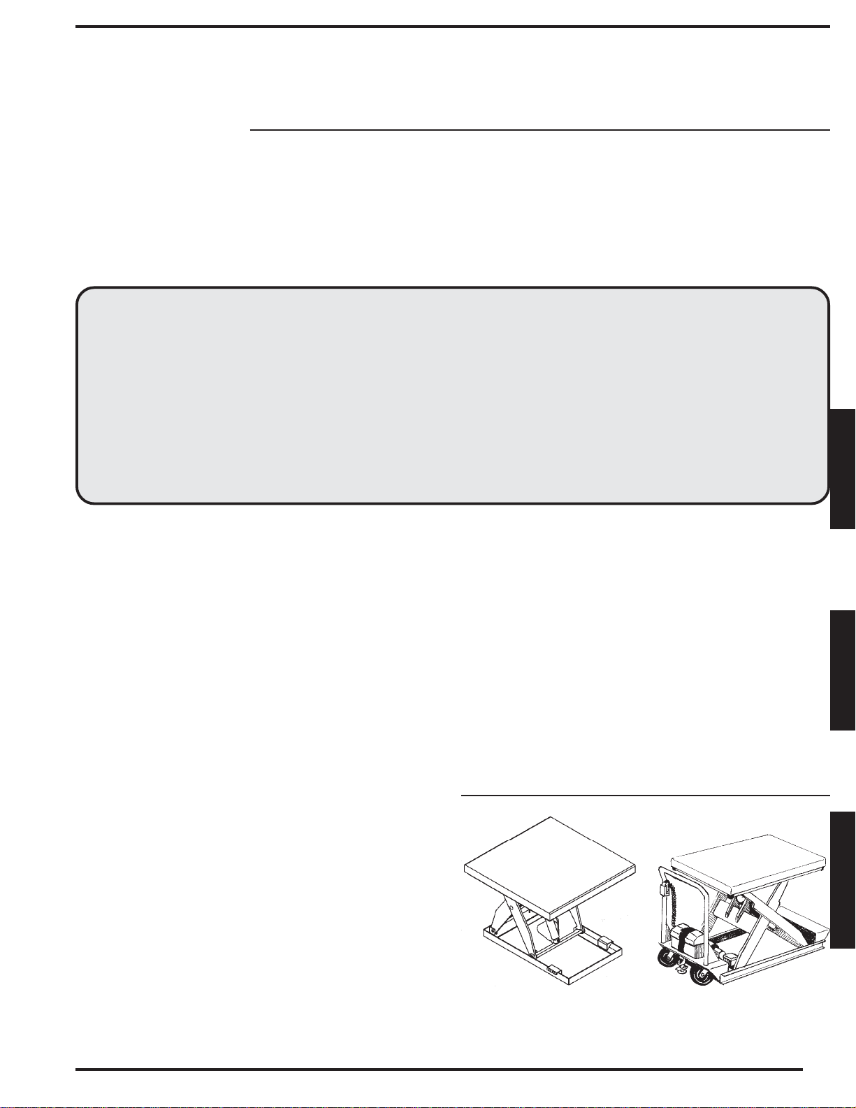
ELECTRIC HYDRAULIC SCISSOR TABLE
Series EHLT & PST
Electrical Diagram - EHLT & PST .............................8
Hydraulic Diagram - EHLT & PST .............................9
Electric/Hydraulic Parts List - EHLT & PST ......... 10
Parts List & Drawing - EHLT ............................ 11-12
Parts List & Drawing - PST .................................... 13
Trouble Shooting Guide - EHLT & PST .......... 14-15
Limited Warranty - EHLT & PST............................. 15
Warning Label Identification - EHLT.................... 16
RECEIVING INSTRUCTIONS
Every unit is thoroughly tested and inspected prior to
shipment. However, it is possible that the unit may incur
damage during transit. If you see damage when unloading,
make a note of it on the BILL OF LADING. Remove all
packing and strapping material, inspect for damage. IF
DAMAGE IS EVIDENT, FILE A CLAIM WITH THE
CARRIER IMMEDIATELY! Also, check the unit size, type
of power unit, etc., to ensure the unit is correct for the
intended application.
MODEL NUMBER AND CAPACITY
The model number, serial number and capacities are
inscribed on the nameplate. Please remember to include
these numbers in any correspondence with you dealer or
the factory.
EHLT PST
ELECTRIC HYDRAULIC SCISSOR TABLES
Series EHLT & PST
1
E
N
G
L
I
S
H
E
S
P
A
N
O
L
F
R
A
N
Ç
A
I
S
Page 2

INSTALLATION INSTRUCTION - MODEL EHLT
Review this entire page before installing the lift. Consult the factory in the event there are any questions or problems at
the time of installation.
The scissor-lift must be removed from the shipping wood and securely anchored to the floor before use!
• The standard model scissor lift table is suitable for use indoors in most industrial locations and many commercial
locations, and is typically provided as a turnkey system. Anchoring the unit to the floor and an electrical supply is
typically all that is required for installation.
• Modifications or additions to the lift without prior manufacturer's authorization may void the lift's warranty (see ANSI
MH29.1, Safety Requirements for Scissor Lifts, section 12.6). The addition of ancillary equipment to the platform
may necessitate that its load capacity be reduced.
• The installation must be made so that it complies with all the regulations applicable to the machine and its location.
The end-user must verify that the supplied equipment is installed so it will be suited to the environment in which it will
be used.
• Installation must be performed by suitably trained personnel with access to the appropriate equipment. The electrical
aspects of the installation should be performed by an electrician.
Note: If the unit is to be placed into a pit, you will need to first determine how the required electrical (and
possibly hydraulic) connections will be made once the unit is in place.
------------------------------------------------------------------------------------------------------
For installation you will need the following:
1. A fork truck or hoisting means.
2. Lag bolts, a masonry drill, a masonry bit, a wrench to fit the lag bolt nuts, grout, and steel shims. Consult the
building's architect or facility engineer to determine the best size and type of hardware with which to anchor the
machine to the floor.
3. A power supply circuit matching the motor voltage and current requirements. Refer to the labels on the control
enclosure and to the electrical section in this manual for more information. The end-user is responsible for supplying
the branch circuit's required overcurrent and short-circuit protection.
------------------------------------------------------------------------------------------------------
1. Move the lift into place with straps or forks placed under the table's frame. Use care to avoid damage to the
electrical or hydraulic components inside the lift.
2. Temporarily connect the power supply to the pigtail cord supplied with the table, and raise the platform so the table's
safety maintenance props can be utilized. Lower the platform so the unit is supported by the props.
3. Anchor the frame to the floor through the 3/4" holes located near the frame corners.
4. Shim and/or grout under the full length of the frame sides.
5. Make permanent connection to the power supply, using an appropriate wiring method.
6. Operate the lift through several full up/down cycles. Verify that the upper travel limit switch (mounted in the frame)
and the toe guard switches (around the perimeter of the platform) function property.
7. Check the hydraulic oil level. It should be filled to within 1" to 1-1/2" of the reservoir's fill hole. If oil is needed, use an
anti-wear hydraulic oil with a viscosity grade of 150 SUS at 100°F (ISO 32 at 40°C) or a non-synthetic automatic
transmission fluid.
8. Clean up any debris or spilled oil, and verify that all of the warning and safety labels are intact.
If the platform must be raised without first having the proper power supply connected, raise the platform at the end of
the table through which the power supply cord enters the frame. Use caution to avoid damage to the perimeter pinch
(toe) guard! Use lifting chains with hooks fastened on each side, near the end of the platform, or insert a lift truck's forks
under the end of the platform.
standing on the ends of the shipping 4 x 4's on that end of the lift while the platform is raised.
Take care to not damage the hanging aluminum toe guard.
Hold the frame down by
2
Page 3

OPERATION INSTRUCTIONS - EHLT & PST
Consult ANSI MH29.1, Section 12 for the owner's/user's responsibilities regarding the operation, care, and
maintenance of this machine.
Ensure that all employees involved in the operation of this lift understand and follow the following instructions!
LOADING:
The load rating, in pounds, is shown on the machine dataplate located on the right corner of the hinged end of the
platform. It indicates the net capacity of the lift with the load centered and evenly distributed on the platform.
Warning:
- that could cause the roller end of the platform to tip up and dump the load. For applications involving side or end edge
loading, consult the factory.
Note:
determining the maximum working load to be placed on the table.
Warning:
exceeding the listed capacity.
The platform's rollers are not captured. Therefore, do not overhang any load at the hinged end of the platform
The addition of any ancillary equipment to the platform by third parties must be taken into account when
Do not exceed the lift's load ratings. Permanent damage to the lift or injury to personnel could result from
OPERATION:
Inspect the perimeter pinch point guards' operation daily.
Warning:
any part of the platform before lowering the unit.
Caution:
The lift is furnished with either a constant-pressure (dead-man style) push button (standard) or twin foot switch (optional)
control.
Pressing the "UP" push-button or foot switch will turn on the power unit to raise the platform. The platform will raise only while
the control is pressed. Upon releasing the control, the platform will stop and hold its position.
Pressing the "DOWN" push-button or foot switch will energize the lowering valve to allow the platform to descend by gravity
(the motor does not run). Again, releasing the control will stop the platform movement, and the unit will hold its position.
Caution:
malfunctioning. Notify your supervisor or maintenance personnel if you notice anything out of the ordinary.
Keep all personnel clear of the machine when it is in operation. Be certain no part of any person or object is under
Always carefully watch the lift and any load on it when it is in operation.
Never use the lift if any damage or unusual noise is observed, if it is in need of repairs, or if it seems to be
E
N
G
L
I
S
H
On DC-powered units, attempting to raise the lift when the battery is low will cause the motor relay protection to prevent the
motor's operation. Adequate battery voltage is indicated by a green LED on the motor relay. See the next page for more
notes regarding operation of battery-powered units.
Ensure that all safety and warning labels stay in place and are legible. Refer to the labels page in this manual.
ORDERING REPLACEMENT OR EXTRA PARTS:
Our company takes pride in using the finest available parts for our equipment. We are not responsible for equipment failure
resulting from the use of unapproved replacement parts. To order replacement or extra parts for your equipment contact
Customer Service at the factory. In any correspondence with the factory please include the Serial Number which is inscribed
on the nameplate of the piece of equipment. Use only the part numbers provided in this Owner's Manual. When ordering
parts for AC power units please indicate the motor phase and voltage that the equipment is operating on.
3
Page 4

ADDITIONAL INSTRUCTIONS FOR BATTERY-POWERED UNITS - PST
• Working with or near lead acid batteries is dangerous. Batteries contain sulfuric acid and produce explosive gases. A
battery explosion could result in loss of eyesight or serious burns.
• Do not smoke or allow a spark or flame near batteries. Charge batteries in locations which are clean, dry, and wellventilated. Do not lay tools or anything metallic on top of any battery. All repairs to a battery must be made by
experienced and qualified personnel.
• When working with batteries, remove personal items such as rings, bracelets, necklaces, and watches. Batteries can
produce enough energy to weld jewelry to metal, causing a severe burn.
• Always have fresh water and soap nearby in case battery acid contacts skin, clothing, or eyes.
• Operating the battery with a low battery voltage can cause premature motor contact failure.
• Do not expose the lift or charger to rain or adverse conditions.
• Replace defective cords or wires immediately.
• Check the battery's water level frequently.
Battery Charger Operating Instructions
Never operate the charger with either of the cables coiled. Operating the unit with the cord wrapped around itself could
cause the cord to overheat, melt, and cause a short-circuit or a fire.
Plug the charger into a standard 115V receptacle. If an extension cord must be used, keep it as short as possible.
Connection: the ribbed wire of the charger's output cord must be connected to the battery's negative (-) terminal. The
non-ribbed wire must be connected to the battery's positive (+) terminal. Reversing this polarity will blow the charger's
output fuse.
When properly connected, the charger will indicate the status of the charger output.
Flashing green, solid red LED - the charger is not seeing a good connection to the battery of the charger's
output fuse has blown.
Solid yellow and red LED's - the charger is providing charging current to the battery.
Solid green and red LED's - the charger is maintaining a fully-charged battery.
CAUTION
cords, receptacles and other equipment.
Troubleshooting:
If unit does not operate, check all of the wiring connections to make sure they're both mechanically and electrically
sound - specifically at the battery, the motor, and at any location a wire is connected to the chassis. Also make sure the
quick-connection plug on the end of the pendant control cord is plugged in correctly.
A fully-charged lead acid battery in good condition at room temperature should read 12.65 volts. At 11.9 volts it is
considered to be fully discharged and in need of charging. When check battery voltage, wait at least 1/2 hour after the
charger has been turned off before checking the batter's voltage.
If the batteries don't seem to be taking a charge, check the charger's 115V supply circuit, the charger's 10A output
fuse, and the charger's output with a voltmeter. If all check okay, confirm the battery's state of charge using a
hydrometer or a voltmeter.
: Remember to unplug the charger before moving the equipment. Failure to do so could cause damage to
4
Page 5

ROUTINE MAINTENANCE & SAFETY CHECKS - EHLT & PST
Warning: Care should be taken to identify all potential hazards and comply with applicable safety procedures before
beginning work.
Warning: Raise the platform and install the maintenance props before beginning any inspections or work on the unit.
Only qualified individuals trained to understand mechanical devices and their associated electrical and hydraulic circuits should
attempt troubleshooting and repair of this equipment.
(A) BEFORE EACH USE INSPECT FOR THE FOLLOWING:
1.) Frayed wires
2.) Oil leaks
3.) Pinched or chafed hoses
4.) Damage or structural deformation to the structural members, the cylinder brackets, etc.
5.) Unusual noise or binding, or evidence thereof.
6.) Proper functioning of all limit switches, including those on the perimeter pinch point guard (if applicable).
(B) INSPECT MONTHLY FOR:
1.) The oil level. Oil should be 1-1/2" to 2" below the reservoir's fill hole with the lift in the fully raised position.
2.) Worn or damaged hydraulic hoses and electrical wires.
3.) Pivot point wear.
4.) Rollers' looseness and wear.
5.) Integrity of the retaining rings on all rollers and at all pivot points.
6.) The integrity of the frame anchor bolts, and for cracks in the concrete around them.
(Non-portable table units only.)
7.) Looseness, wear, or damage to the casters' bearings, mounting hardware, or surface material.
(Portable units only.)
8.) Proper functioning of any hand- or foot-operated mechanisms.
9.) Proper water level in the battery.
10.) Unusual noises or movement during operation.
11.) All the information, safety, and warning labels being in place and in good condition.
12.) The need to clean off dirt and debris.
E
N
G
L
I
S
H
(C) YEARLY INSPECTIONS
The oil should be changed if the oil darkens, becomes gritty, or turns a milky color (indicating the presence of water).
Replace with an anti-wear hydraulic oil with a viscosity grade of 150 SUS at 100°F, (ISO 32 at 40°C). Ex: AW 32 or
HO 150 hydraulic oil, or a non-synthetic transmission fluid. You may use a synthetic transmission fluid if you flush
the system with the synthetic fluid before filling the reservoir.
5
Page 6

THE POWER UNIT'S OPERATION - EHLT & PST
The electric/hydraulic scissor lift utilizes an electric motor directly coupled to a gear-type hydraulic pump to produce
the needed fluid pressure and flow to allow the cylinders to perform the work of lifting the platform load.
A hydraulic manifold houses the hydraulic control components, and is bolted directly onto the gear pump.
The power unit's hydraulic components are all rated for 3,000 psi working pressure.
Important parts of the power unit include:
• The electric motor. Motors are available for operation on single- or three-phase. AC supplies (all are dual-voltage
capable), or on a 12 VDC battery.
• The gear pump. Its shaft is coupled directly to the shaft of the electric motor. Several displacements are available,
depending on the motor horsepower used.
• The check valve. Its purpose is to prevent the backflow of fluid through the pump. In this way it allows the platform
to be held at a given elevation indefinitely.
• The pressure relief valve. Its job is to open a path for fluid to flow back to the reservoir in the event that the fluid
pressure built up by the pump exceeds 3,000 psi. Thus the pump cannot generate more than 3,000 psi.
• The lowering solenoid valve. This is an electrically-operated cartridge valve. It contains a screen to keep
contaminants from entering the valve.
• The pressure-compensated flow control spool. This rests under the lowering valve, and regulates the fluid flow back
to the reservoir when the valve opens. It allows the table to always lower at the same rate regardless of whether
there is a load on the platform or not. Several sizes are available.
• The hydraulic lift cylinder(s). These are displacement-style cylinders. They have a bleeder valve located at their top
endto allow air to be bled fro the hydraulic system.
• The safety velocity fuse. This is a devise that is installed in the cylinder's hose port. It closes quickly in the event of
a catastrophic hose failure to prevent the lift from collapsing down. The platform remains stationary until pressure is
reapplied to the system.
• The hydraulic fluid. The system uses HO150 hydraulic fluid. Any anti-wear hydraulic oil with a viscosity grade of
150 SUS at 100°F (ISO 32 at 40°C) such as AW 32 or a non-synthetic transmission fluid is acceptable.
When the platform is to be raised, press the "UP" push-button or foot switch. The motor turns, and in turning it spins
the hydraulic gear pump. Oil is drawn from the reservoir through the suction filter and into the pump. The pump pushes
the then-pressurized oil through the check valve and out to the lift cylinders.
When the platform is to be lowered, press the "DOWN" push-button or foot switch. The lowering valve opens,
bypassing the check valve and allowing the oil in the cylinders to return back to the reservoir through the return hose.
The rate at which the platform lowers is regulated by the internal pressure-compensated flow spool.
In the event that the platform creeps down slowly after releasing the "DOWN" control, it will be necessary to remove
the lowering cartage valve for inspection and cleaning, as follows:
• Remove any load from the platform.
•
Warning:
• Remove the nut holding the solenoid coil on the valve stem, and then unscrew the valve from the manifold.
• Inspect the valve for contaminants, and the valve's o-rings and back-up washers for cuts, tears, and other damage.
• With the valve immersed in mineral spirits or kerosene, use a thin tool such as a small screwdriver or a small hex
wrench to push the poppet in and out several times from the bottom end of the valve. The valve should move freely,
about 1/16" from closed to open position. If it sticks in, the valve stem could be bent and will need to be replaced if
it doesn't free up after cleaning. Blow the valve off with a compressed-air gun while again pushing the poppet in and
out.
• Inspect the bottom of the manifold's valve cavity for contaminants.
• Again with the thin tool, press on the middle of the flow control spool located in the bottom of the cavity. It should
move down and back up freely.
• Reinstall the valve into the manifold, tightening the valve with approximately 20 lb-ft of torque.
If the platform lowers extremely slowly or not at all, the cylinder's velocity fuse could be closing. This can be caused
by air in the hydraulic cylinders. To bleed the air from the system:
• Remove any load from the platform.
•
Warning:
• Hold a rag over the cylinder's bleeder valve (it looks like a grease zirk) and open valve about 1/2 turn with a 1/4"
wrench. Oil and air will sputter from the valve - once no air is observed, close the valve.
Raise the lift and install the maintenance props. Lower the platform until the lift rests on the props.
Raise the lift and install the maintenance props. Lower the platform until the lift rests on the props.
6
Page 7

MOTOR & TRANSFORMER CONNECTION DIAGRAM - EHLT & PST
CAUTION!
match the new motor voltage also.
If the motor voltage is changed, the wire on the control transformer's primary wire has to be changed to
.5 HP, .75 HP AND 3 HP SINGLE-PHASE MOTORS AND FOR
MOTOR LEAD CONNECTION DIAGRAM FOR ALL
ALL 2 HP, 5 HP, AND 6.5 HP THREE-PHASE MOTORS
E
N
G
L
I
S
H
* The two thermostat leads go to: 1) the grounded side of the transformer secondary, and 2) the motor relay coil, in either order.
aa
aBE SURE ALL POWER IS OFF BEFORE ATTEMPTING TO WORK ON THIS EQUIPMENT!
aa
CAUTION: SERVICE WORK SHOULD BE PERFORMED ONLY BY TRAINED & QUALIFIED PERSONNEL.
7
Page 8

ELECTRICAL DIAGRAM - EHLT & PST
Warning: Care should be taken to identify all potential hazards and comply with applicable safety procedures before
beginning work. Fully lower or securely support the platform, and ensure that system pressure and power have
been removed, before attempting to work on any of the hydraulic components!
Only qualified individuals trained to understand mechanical devices and their associated electrical and hydraulic
circuits should attempt troubleshooting and repair of this equipment.
8
Page 9

HYDRAULIC DIAGRAM - EHLT & PST
Warning:
procedures before beginning work. Fully lower or securely support the platform, and ensure that system pressure
and power have been removed, before attempting to work on any of the hydraulic components.
Only qualified individuals trained to understand mechanical devices and their associated electrical and hydraulic
circuits should attempt troubleshooting and repair of this equipment.
Caution:
with a viscosity of 150 SUS at 100°F (ISO 32 at 40°C) or a non-synthetic transmission fluid.
Care should be taken to identify all potential hazards and comply with applicable safety
Do not use brake fluid or jack oils in the hydraulic system. If oil is needed, use an antiwear hydraulic fluid
E
N
G
L
I
S
H
9
Page 10

ELECTRIC/HYDRAULIC BOM - EHLT & PST
Item#
1
2
3
4
5
6
7
8
9
10
11
12
13
14
15
16
17
18
19
20
21
22
23
24
25
26
27
28
29
30
31
32
33
34
35
36
Qty
1
1
1
1
1
1
1
1
1
1
1
1
1
1
1
2
1
1
1
1
1
1
1
1
2
2
1
1
1
1
1 or 2
1
1
1
1
1-1/2
Part Number
Electrical parts used only on AC lifts:
01-135-XXX
S11.310-24AC
01-129-001
AGC 2
01-029-006
01-522-015
99-034-008
01-033-017
01-033-015
Electrical parts used only on DC lifts:
01-135-036
15-022-004
99-034-010
MDL-15
15-139-001
01-033-024
SY6319GI
A-402DSC
01-522-019
15-034-003
332-901
831613C3EB
AB443JS
Electrical parts used on both AC & DC lifts:
01-022-001
01-033-009
159/D
01-022-022
Hydraulic parts used on all standard
scissor lifts:
99-153-005
99-153-015
99-153-011
99-153-024
1
99-021-XXX
99-127-001
01-143-XXX
DPS-40-N06
01-031-005
HO 150
Part Description
Motor; varies by customer spec; contact factory
Motor contactor, 30A, w/24 VAC coil
Transformer, control; w/ 24 VAC secondary
Fuse, for control circuit
Control enclosure, 6"W x 6"L x 4"D
Push-button control on 8' cord
Solenoid coil, 24 VAC
Connector cord, for solenoid coil
Cord, power, 14/3, 9' long, w/ NEMA 5-15 plug (115V units only)
Motor, 12 VDC, 2000W
Motor relay, "SmartStart"
Solenoid coil, 12 VDC
Fuse, charger output
Battery, 12 VDC, deep-cycle
Quick-connect cord (with 4-pin plug)
Cable connector, to battery
Junction box, 2"W x 4"L x 2"D
Push-button control on 18" - 90" coil cord
Battery charger, 12 VDC, 15 amp
BCI (battery charge indicator) (option)
Push-to-test button for BCI (option)
Junction box, 4"W x 4"L x 3"D (option)
Limit switch, roller-arm (N.C.)
Cable, 18/2 coil cord, 18" - 90" (to toe guard switches)
Multi-pole terminal strip
Toe guard switch
Valve, relief, 210 bar
Valve, solenoid, N.C.
Valve, check
Flow control spool, 2 gpm
Cylinder, displacement; varies by model; contact factory
Manifold, lift-hold-lower
Pump, hydraulic; varies by model; contact factory
Breather plug
Fitting, intake screen
Hydraulic fluid (gallons)
10
Page 11

EXPLODED PARTS DRAWING
Scissor Table - Model EHLT
25
24
21
26
19
18
1
22
23
2
3
17
16
E
N
G
L
I
S
H
3
4
9
30
14
13
12
3
20
10
15
11
7
8
5
6
28
11
Page 12

PARTS IDENTIFICATION - Scissor Table - Model EHLT
ITEM
NUMBER
1
2
3
4
5
6
7
8
9
10
11
12
13
14
DESCRIPTION
Pin, Roller 3/16" dia. x 1-1/8" lg.
Pin, Cylinder Pivot 1-1/8" dia.
Bearing, Sleeve 1-1/8" dia. x 3/4" lg.
Cylinder, Hydraulic 3" dia x 10" stk
Roller, 3-1/4" dia. x 3/4"w
Bearing, Sleeve 1-1/8" dia. x 5/8" lg.
Washer, Thrust Bearing 1-1/8" dia. x .06 thk.
Retainer Snap Ring 1-1/8" dia. External
Washer, Thrust Bearing 1-1/2ID x .06 thk.
Pin, Hinge 1-1/8 dia.
Shim, Machinery Bushing 1-1/8" ID x .06 thk.
Pin, Scissors Pivot 1-1/2" dia.
Bolt, Shoulder 3/8" dia. x 1-1/2" lg.
Bearing, Sleeve 1-1/2" dia x 1-1/2" lg.
ENGINEER
NUMBER
a/l
24-112-02
01-111-002
99-021-901
01-027-001
01-111-001
01-115-001
a/l
01-115-003
01-112-004
a/l
01-112-019
a/l
01-111-003
PART
NUMBER
a/l
ST-CYLPIN
ST-CYLBRG
ST-CYL
ST-RLR
ST-RLRBRG
ST-TRBRG
a/l
a/l
ST-HP
a/l
ST-SPP
a/l
ST-BRG
QTY
1
1
6
1
4
4
8
12
4
4
4
2
2
2
15
16
17
18
19
20
21
22
23
24
25
26
27
29
30
Bolt, Cylinder Retainer
Nut, Hex Nylock 1/4-20 unc
Washer, Flat 1/4 nom ID
Toe Guard Support
Screw, Hex HD 1/4-20 unc x 2-1/2" long
Nut, Hex Jam 1/2-13 unc
Screw, #8-32 x 1/2 lg Flat HD Socket Cap
Toe Guard Actuator
Specialty Hardware, Toeguard
Switch, Electrical Limit N.C.
Screw, #4-40 x 1/2 lg. Button Head Sock Cap
Toe Guard End L-Shaped
Toe Guard Side L-Shaped
Shim, Machinery Bushings 1-1/2" dia. x .06 thk
Nut, Hex Nylock 5/16-18 unc
01-118-001
a/l
a/l
01-015-009
a/l
a/l
a/l
01-015-008
01-145-010
01-022-022
a/l
01-015-912
01-015-912
a/l
a/l
ST-CRB
a/l
a/l
ST-TGCNR
a/l
a/l
a/l
ST-TGA
ST-HDW
ST-LS
a/l
ST-TGAE
ST-TGAE
a/l
a/l
1
4
4
4
4
1
2
2
2
2
4
2
2
2
2
**PLEASE SUPPLY SERIAL NUMBER AT TIME OF ORDER**
12
Page 13

EXPLODED PARTS DRAWING & PARTS LIST
Portable Scissor Table - Model PST
ITEM
NUMBER
1
2
3
4
5
6
8
9
10
11
12
14
15
17
18
19
19
19
19
19
19
19
20
20
21
22
23
24
25
26
27
**PLEASE SUPPLY SERIAL NUMBER AT TIME OF ORDER**
DESCRIPTION
8 x 2 Phenolic Rigid Caster
Roller
Snap Ring
12V DC Motor
Hydraulic Pump
Manifold with Valves (lift hold lower)
8 x 2 Phenolic Swivel Caster
3/8 x 5 Carriage Bolt with Lock Nut
Junction Box
Hand Control
Floor Lock (Side Lever Actuated)
Battery Box with Lid and Strap
12V DC Battery
Toe Guard Corner
Bolt and Nut
2 x 10 Displacement Type Cylinder
2-1/2 x 10 Displacement Type Cylinder
2-1/2 x 10 Displacement Type Cylinder
3 x 10 Displacement Type Cylinder
3 x 10 Displacement Type Cylinder
2-1/2 x 10 Displacement Type Cylinder (2 req)
2-1/2 x 10 Displacement Type Cylinder (2 req)
Single Cylinder Upper Cylinder Pin
Dual Cylinder Upper Cylinder Pin
Cylinder Retaining Bolt
Toe Guard Limit Switch
Toe Guard Actuator
Toe Guard Limit Switch Hardware
Specialty Hardware
Screw #8-32 x 1/2
Up Travel Limit Switch (Roller Arm)
Limit Switch Kit (Inc. switch, actuator and hdw)
ENGINEER
NUMBER
PH-8/2-R
01-027-001
68021
01-135-036
01-143-006
99-127-001
PH-8/2-S
21373-37024
PST-J-BOX
01-522-022
FL-LK-SMR
15-139-002
15-139-001
01-015-009
11013-36209
99-021-903
99-021-906
99-021-906
99-021-901
99-021-901
99-021-906
99-021-906
01-112-01
01-112-015
01-118-001
01-022-022
01-015-008
01-145-010
01-145-010
81190
MJ1-6114
PST-LS-KIT
GENERIC
NUMBER
PST-CSTR-RGD
PST-RLR
PST-SNPRG
PST-MTR
PST-PMP
PST-MFD
PST-CSTR-SVL
PST-CSTR-HDW
PST-J-BOX
PST-HND-CTL
PST-FL-LK
PST-B-BOX
PST-BAT
PST-TG-CNR
PST-TG-HDW
PST-CYL-1-46
PST-CYL-1-58
PST-CYL-2-46
PST-CYL-2-58
PST-CYL-3-46
PST-CYL-3-58
PST-CYL-4
PST-CYL-UPN-1
PST-CYL-UPN-2
PST-CYL-RET-BLT
PST-TG-LS
PST-TG-ACTR
PST-TG-LS-HDW
PST-TG-SPHDW
PST-TG-SC
PST-UTLS
PST-LS-KIT
E
N
G
L
I
S
H
13
Page 14

TROUBLESHOOTING GUIDE - EHLT, PST
WARNING: Care should be taken to identify all potential hazards and comply with all applicable safety procedures
before beginning troubleshooting or repairs.
CAUTION: Before performing any troubleshooting or repairs, the load must be removed from the platform. Then either
raise the platform and install the maintenance props or fully lower the platform to the floor.
Only qualified individuals trained to understand mechanical devices and their associated electrical and hydraulic
circuits should attempt troubleshooting and repair of this equipment.
Consult the factory for problems at time of installation, or for any problems not addressed in this manual.
* Check the DC notes page for troubleshooting other problems specific to batteries and charges.
PROBLEM
1) Problem unit doesn't run when
"UP" button is pressed.
2) Motor runs, platform doesn't
move. Power unit not noisy.
3) Motor hums or pumps squeals,
but the platform does not move,
or the platform moves only slowly.
POSSIBLE CAUSE(S)
a) Transformer fuse is blown.
b) No supply voltage.
c) Upper-travel limit switch is
engaged or bad.
d) Bad control transformer.
e) Bad motor relay coil.
f) Battery voltage low (DC units).
a) Motor rotation is wrong (AC-
powered units only).
b) Pump is failing to build pressure.
a) See last paragraph, above.
b) Excess voltage drop to motor, due
to power wire size too small, wire
run too long, or incoming voltage
too low.
c) Motor is "single-phasing".
d) Pressure relief opening at full
pressure.
e) Contamination holding open the
lowering valve or the check valve.
ACTION
a) Test with meter; replace if bad.
b) Test with meter. Check fuses,
breakers, and overloads to
determine the causes.
c) Inspect, test switch. Replace if
bad. Check for 24 VAC; replace if
bad.
d) Test with meter; replace if bad.
e) The green LED on motor relay will
be off, or will turn off when the UP
push-button is pressed.
f) Test with meter. Change battery if
low (is motor relay LED on?)
a) Verify motor runs CW, opposite the
shaft end.
b) Consult factory.
a) Same as above.
b) Check power installation for
adequacy. Check incoming voltage
while
motor is running. Correct
problem found.
c) Determine cause of loss of voltage
on one phase; correct.
d) Check for structural damage or
binding of the scissor legs, etc.
check for platform overload
condition.
e) Remove and inspect. Clean per
instructions in this manual.
4) Platform raises, then drifts down.
5) Spongy or jerky platform
movement.
6) Platform won't lower.
14
a) See last paragraph, above.
a) Excessive air in the hydraulic
cylinders.
b) Toe guard is actuated.
a) Toe guard switch, or wire, broken.
b) Solenoid coil is bad.
a) Same as above.
a) Bleed air per procedures described
in this manual.
b) Check for a toe guard extrusion or
rubber corner that is stuck.
Adjust if necessary.
a) Inspect visually, check with
multimeter. Repair as needed.
b) Check with multimeter on
diodecheck function. (Reading for
ohms will not provide an accurate
test of the coil.)
Page 15

PROBLEM
POSSIBLE CAUSE(S)
c) Physical blockage of the structure.
d) Solenoid valve or suction hose
screen plugged.
ACTION
c) Inspect for foreign material or
objects that might block the leg set
or its rollers.
d) Remove and inspect. Clean per
instructions in this manual.
7) Platform lowers too slowly.
8) Platform lowers too quickly.
CAUTION:
Do not use brake fluid or jack oils in the hydraulic system.
a) Pinched hose.
b) Velocity fuse locking (platform
only slowly creeps down).
c) Flow control spool sticking.
a) See last paragraph, above
a) Check pressure, supply, and return
hoses for kinks.
b) Same as for jerky platform
movement.
c) Remove plug from FC port; push
on flow spool to ensure it is fully
pressed into the cavity. Pull and
clean the spool if necessary.
a) Same as above.
If oil is needed, use an anti-wear
hydraulic oil with a viscosity grade of 150 SUS at 100°F (ISO 32 at 32°C) or a non-synthetic
transmission fluid.
LIMITED WARRANTY
ONE YEAR LIMITED WARRANTY. The manufacturer warrants for the original purchaser against defects in materials
and workmanship under normal use one year after date of purchase. (Not to exceed 15 months after date of manufacture.) Any
part which is determined by the manufacturer to be defective in material or workmanship and returned to the factory, shipping
costs prepaid, will be, as the exclusive remedy, repaired or replaced at our option. Labor costs for warranty repairs and/or
modifications are not covered unless done at manufacturer’s facilities. Any modifications performed without written approval of
the manufacturer may void warranty. This limited warranty gives purchaser specific legal rights which vary from state to state.
E
N
G
L
I
S
H
LIMITATION OF LIABILITY. To the extent allowable under applicable law, the manufacturer’s liability for consequential
and incidental damages is expressly disclaimed.
The manufacturer’s liability in any event is limited to, and shall not exceed, the purchase price paid. Misuse or modification may
void warranty.
WARRANTY DISCLAIMER. Our company has made a diligent effort to illustrate and describe the products shown
accurately; however, such illustrations and descriptions are for the sole purpose of identification, and do not express or imply
a warranty that the products are merchantable, or fit for a particular purpose, or that the products will necessarily conform to the
illustrations or descriptions.
The provisions of the warranty shall be construed and enforced in accordance with the UNIFORM COMMERCIAL CODE
and laws as enacted in the State of Indiana.
DISPOSITION. Our company will make a good faith effort for prompt correction or other adjustment with respect to any
product which proves to be defective within the Limited Warranty. Warranty claims must be made in writing within said year.
15
Page 16

WARNING LABEL IDENTIFICATION
MAKE SURE ALL WARNING LABELS ARE IN PLACE!
NOTE:
8
2
5
6
3
Labels 1 & 7 are located
on junction box cover
1
NOTICE NOTA AVIS
POWER SUPPLY: 115 Volt/1 Phase/60 HZ
CONTROL VOLTAGE: 24 VOLT AC
CORRIENTE: 115 Volt/1 Fase/60 HZ
VOLTAJE DE CONTROL: 24 VOLT CA
ALIMENTATION ÉLECTRIQUE: 115 Volt/1 Phase/ 60 HZ
VOLTAGE DE CONTRÔLE: 24 VOLT AC
2
ON HYDRAULIC TANK (NOT SHOWN)
248
3
1, 7
4
*Product safety signs or labels should be
periodically inspected and cleaned by the
product users as necessary to maintain
good legibility for safe viewing distance . . .
ANSI 535.4 (10.21)
Contact manufacturer for replacement
labels if needed.
7
DANGER
!
PELIGRO
!
DANGER
!
SHUT POWER OFF AND CONSULT
OWNERS MANUAL BEFORE WORKING
ON THIS EQUIPMENT
CORTE LA CONSULTE Y CONSULTE EL
MANUAL DEL PROPIETARIO ANTES DE
TRABAJAR EN ESTE EQUIPO
COUPER LE COURANT ET CONSULTER
LE MANUEL D’UTILISATION AVANT DE
TRAVAILLER SUR CET ÉQUIPEMENT
8
TO AVOID PERSONAL INJURY READ
DANGER
!
PELIGRO
!
ATTENTION
!
OWNER’S MANUAL BEFORE OPERATING
OR REPAIRING SCISSOR LIFT
PARA EVITAR DAÑOS PERSONALES
LEA EL MANUAL DEL PROPIETARIO
ANTES DE OPERAR O REPARAR EL
ELEVADOR DE TIJERAS
POUR ÉVITER TOUTE BLESSURE
PERSONNELLE LIRE LE MANUEL
D'UTILISATION AVANT DE METTRE EN
MARCHE OU AVANT DE RÉPARER
L’ÉLEVATEUR CISEAU
3
!
SECURE FRAME
4
!
KEEP CLEAR
WHEN IN USE
BOTH SIDES & FRONT END
5
WARNING
!
KEEP CLEAR OF
PINCH POINT
6
PARA INSTRUCCIONES DE USO Ó CONSULTAS CONTACTAR
221
DO NOT PUT HANDS, FEET OR
OBJECTS UNDER TOP. LOWER
PLATFORM SLOWLY.
NO PONGA MANOS, PIES U
OBJECTOS DEBAJO DEL
BORDE. DESCIENDA LA
PLATAFORMA LENTAMENTE.
NE PAS METTRE LES MAINS,
LES PIEDS OU TOUT OBJET
SOUS LE PLATEAU SUPÉRIEUR.
DESCENDRE LA PLAT-FORM
LENTEMENT
POUR INSTRUCTIONS OU QUESTIONS SUPPLÉMENTAIRES CONTACTER
VESTIL MANUFACTURING. • P.O. BOX 570 ANGOLA, IN 46703 • 1-800-348-0860 OR 260-665-7586205
ISO AW-32
HYDRAULIC OIL OR EQUIVALENT
ACEITE HIDRÁULICO O EQUIVALENTE
HYDRAULIQUE OU ÉQUIVALENT
WARNING
TO FLOOR
WARNING
MANTENGASE ALEJADO DE
PUNTO DE CORTE
FOR USER INSTRUCTIONS OR QUESTIONS CONTACT
DO NOT WORK UNDER LIFT WITHOUT SAFETY
BLOCK OR WHILE LOADED. KEEP CLEAR OF
MOVING SCISSOR LEG MECHANISM.
NO TRABAJE DEBAJO DEL ELEVADOR SIN LOS
FRENOS DE SEGURIDAD O CUANDO ESTÉ
CARGADO. MANTENGASE ALEJADO DEL
MECANISMO DE TIJERA EN MOVIMIENTO.
NE PAS TRAVAILLER SOUS L’ÉLEVATEUR SANS
BLOCS DE SÉCURITÉ OU LORSQU’ IL EST
CHARGÉ. RESTER À L’ÉCART DU MÉCANISME
CISEAU LORSQUE L’ÉLEVATEUR EST EN
FONCTIONNEMENT.
AVISO
!
ASEGURE EL
BASTIDOR AL PISO
AVISO
!
MANTENGASE
ALEJADO CUANDO
SE ESTA OPERANDO
AVISO
!
AVERTISSEMENT
!
FIXER SOLIDEMENT
LE CADRE AU PLANCHER
AVERTISSEMENT
!
SE TENIR À DISTANCE
LORS DU
FONCTIONNEMENT
AVERTISSEMENT
!
SE TENIR À DISTANCE DU
POINT DE PINCEMENT
207
206
204
220
208
DO NOT STAND,
SIT OR
RIDE ON LIFT
NO SE SIENTE, SE
PARE,O VIAJE
EN EL ELEVADOR
NE PAS SE TENIR
DEBOUT,
S’ASSEOIR OU
MONTER SUR
L’ÉLEVATEUR
16
 Loading...