

Page 1
01/11 rev. 10/26/2017 LM, MANUAL
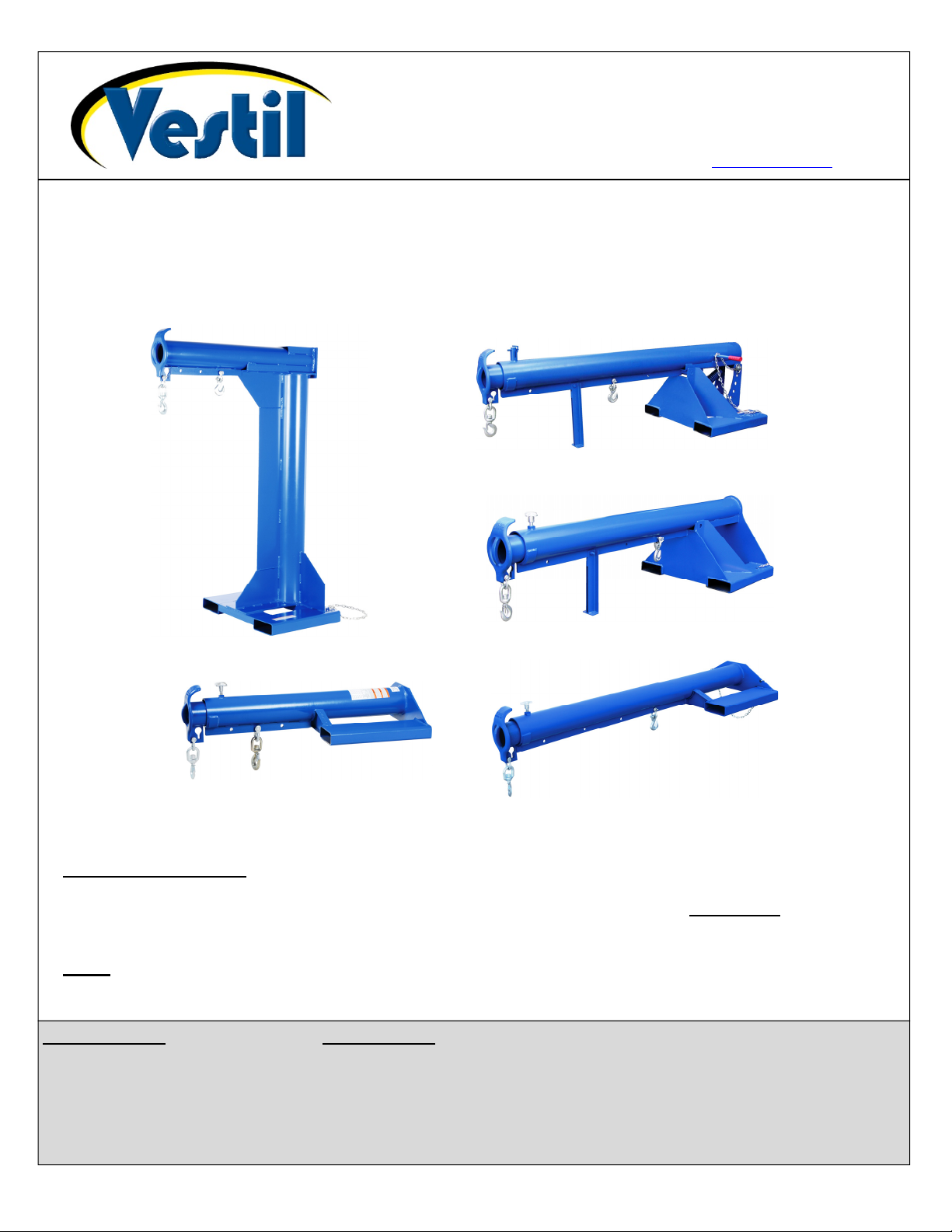
LM-Series and LMS-Series Fork Truck Attachments
VESTIL MANUFACTURING CORP.
2999 North Wayne Street, P.O. Box 507, Angola, IN 46703
Telephone: (260) 665-7586 -or- Toll Free (800) 348-0868
Fax: (260) 665-1339
www.vestilmfg.com e-mail: info@vestil.com
LM-HRT &
LM-HRNT
LMS-EBT &
LMS-EBNT
Use and Maintenance Manual
LM-OBT &
LM-OBNT
LM-1T &
LM-1NT
LM-EBT &
LM-EBNT
Receiving instructions:
After delivery, remove the packaging from the product. Inspect the product closely to determine whether it
sustained damage during transport. If damage is discovered during the inspection, immediately record a
complete description of the damage on the bill of lading. If the product is undamaged, discard the packaging.
NOTE:
The end-user is solely responsible for confirming that product design, installation, use, and maintenance
comply with laws, regulations, codes, and mandatory standards applied where the product is used.
Table of Contents Table of Figures
Signal words……………………… 2 Fig. 1: LM-1T & -1NT Exploded Parts Diagrams, Parts Lists, Center of Gravity………… 3 - 6
Safe use recommendations……. 2 Fig. 2: LM-OBT & -OBNT Exploded Parts Diagrams, Parts Lists, Center of Gravity........ 7 - 10
Safety Recommendations……… 2 Fig. 3: LM-HRT & -HRNT Exploded Parts Diagram, Parts Lists, Center of Gravity…….. 11 - 14
Loading & Use Instructions…….. 23 - 25 Fig. 4: LM-EBT & -EBNT Exploded Parts Diagram, Parts Lists, Center of Gravity……... 15 - 18
Inspections & Maintenance…….. 25 - 26 Fig. 5: LMS-EBT-46 & -EBNT-46 Exploded Parts Diagram, Parts Lists, Centers……….
Labeling diagram…………..……. 27 of Gravity………………………………………………………………………………… 19 - 22
Limited Warranty………………… 28
Copyright 2017 Vestil Manufacturing Corp.
Page 2
01/11 rev. 10/26/2017 LM, MANUAL
SIGNAL WORDS
This manual classifies personal injury risks and situations that might cause property damage with “Signal
words”. Signal words indicate the seriousness of injuries that might result if a particular act or omission occurs.
Identifies a hazardous situation which, if not avoided, WILL result in DEATH or
Identifies a hazardous situation which, if not avoided, COULD result in DEATH or
Indicates a hazardous situation which, if not avoided, COULD result in MINOR or
Identifies practices likely to result in product/property damage, such as operation that might
Safe Use Recommendations:
Vestil strives to identify all foreseeable hazards associated with the use of its products. However, material handling
is dangerous and no manual can address every possible risk. The most effective means for avoiding injury is for the
end user to apply sound judgment whenever using this device.
Material handling is dangerous. Improper or careless operation might result in serious personal
injuries. Acquire a copy of the latest version of ANSI B56.1, which is freely downloadable on www.ITSDF.org. Apply
all relevant portions of Part II “For the User”. The following recommendations are intended to complement the
guidance provided in B56.1.
Always use this boom in compliance with all rules applied to fork truck attachment at your worksite.
Failure to read and understand the instructions included in this manual before using or servicing the boom
constitutes misuse.
DO NOT use a damaged boom. Inspect the boom before each use according to the relevant inspection instructions
that appear on p. 25-26 to determine whether the boom is in normal operating condition.
DO NOT contact electrified wires with the boom.
DO NOT use the boom if the safety chain is damaged or missing. The only purpose of the safety chain is to prevent
the boom from sliding off of the forks—it is NOT intended or designed to bear the full load rating.
DO NOT lift the boom until it is securely connected to the carriage of the fork truck with the restraint strap.
DO NOT attempt to lift a load weighing more than the boom’s maximum rated load. Load ratings for all boom
variants appear on pages 4, 6, 8, 10, 12, 14, 16, 18, 20, and 22.
NEVER lift this boom over people.
DO NOT permit any person to stand beneath or travel under the boom or the load.
Inform everyone in the area that you are going to use the boom. Instruct them to stay clear of the boom and the
supported load during use.
DO NOT allow people to ride on either the boom or the load.
DO NOT use the boom if any product label (see p. 27) is unreadable, damaged, or missing. Contact Vestil to order
a replacement label(s).
ALWAYS apply proper (fork) lift operation practices learned during your training program.
Always make sure that shackle pins (see shackles in exploded parts diagrams, pp. 3-22) are secure before applying
a load to the load hook. Tighten the screw pin before each use.
Before raising the boom from the floor AND before attaching the load to the boom, tilt the fork lift mast away from
the boom to ensure that the boom will not slide towards the tips of the forks.
ALWAYS follow the loading and use instructions that appear on p. 23-25. Failure to properly position a load might
cause a dangerous degree of load swing when the boom is elevated.
Only use the boom to lift loads. DO NOT use the boom to drag items.
Transport loads with the bottom of the load and the forks as low as possible.
Drive suspended loads at low speed. Brake and turn slowly cautiously.
DO NOT modify the boom in any way. Modifications automatically void the limited warranty (see p. 28) and might
make the boom unsafe to use.
SERIOUS INJURY. Use of this signal word is limited to the most extreme situations.
SERIOUS INJURY.
MODERATE injury.
damage the boom.
Copyright 2016 Vestil Manufacturing Co. Page 2 of 28
Page 3
01/11 rev. 10/26/2017 LM, MANUAL
1
1
1
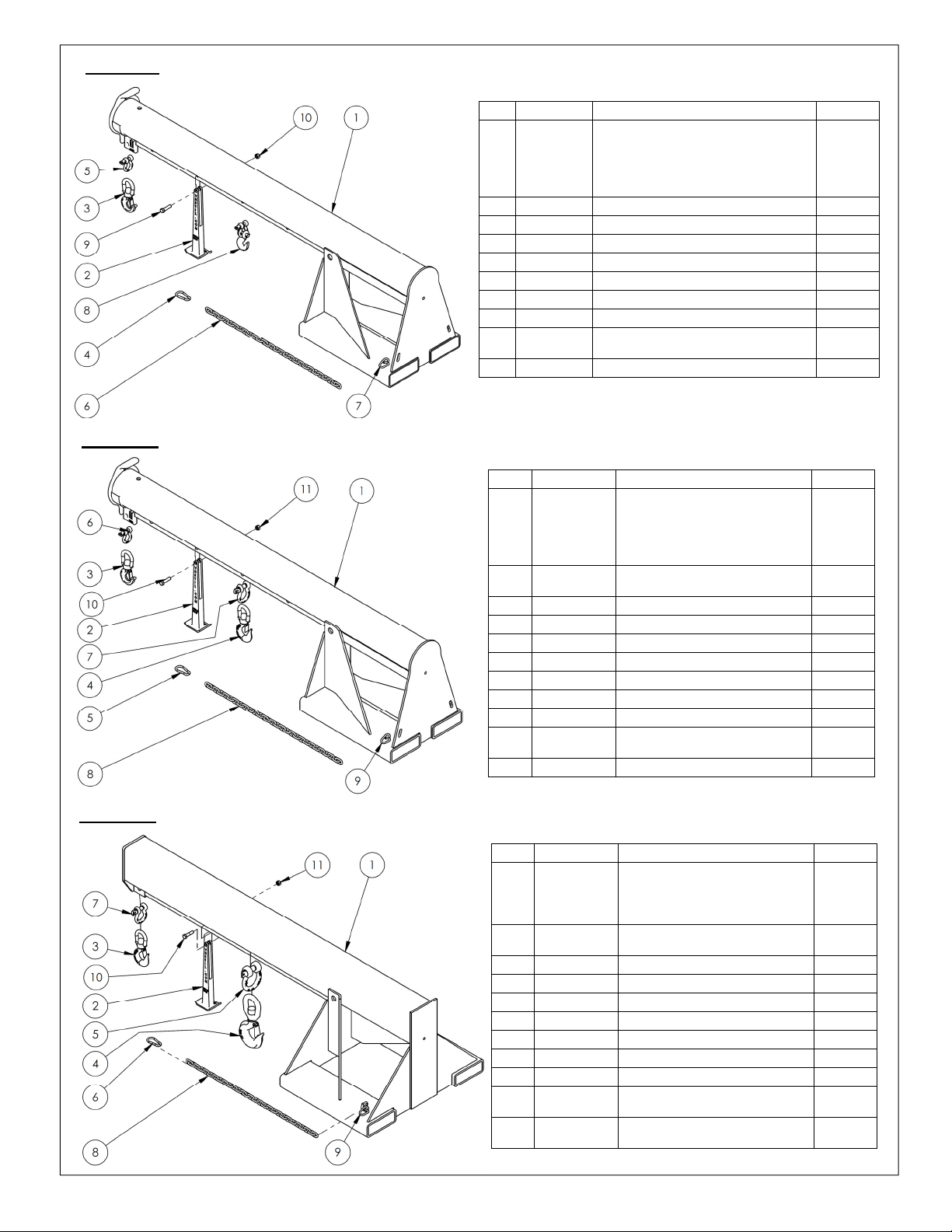
FIG. 1A: LM-1T-3-24 & LM-1T-4k Exploded Parts Diagram & Bill of Materials
FIG. 1B: LM-1T-6k Exploded Parts Diagram & Bill of Materials
Item Part No. Description Quantity
08-514-176
1
08-514-111
08-514-177
08-514-178
2 08-514-261 Weldment, inner tube 1
3 08-014-134 Frame, front support leg casting 1
4 08-025-004 X-handle, locking bolt 1
5 08-145-001 Swivel hook, 2-ton 1
6 08-145-041 5/16” snap hook 1
7 08-145-010 1/2” shackle, 2-ton 1
8 99-145-037 5/16” chain 36” long 1
9 99-145-084 Lap link 1
10 99-645-019 2-ton hook and shackle 1
11 11211
12 36109 1/2” – 13UNC hex nut 1
Weldment, frame, boom/base, 4k:
LM-1T-4-11
LM-1T-4-24 & LM-1T-3-24
LM-1T-4-30
LM-1T-4-36
/2” -13UNC x 2” HHCS zinc-plated
bolt
Item Part No. Description Quantity
08-514-179
1
08-514-113
08-514-180
08-514-181
2 08-514-261 Weldment, inner tube 1
3 08-014-134 Frame, front support leg casting 1
4 08-025-004 X-handle, locking bolt 1
5 08-145-001 Swivel hook, 2-ton 1
6 08-145-002 Swivel hook, 3-ton 1
7 08-145-041 5/16” snap hook 1
8 08-145-010 1/2” shackle, 2-ton 1
9 99-145-019 5/8” 3.25-ton shackle 1
10 99-145-037 5/16” chain 36” long 1
11 99-145-084 Lap link 1
12 11211
13 36109 1/2” – 13UNC hex nut 1
Weldment, frame, boom/base, 6k:
LM-1T-6-11
LM-1T-6-24
LM-1T-6-30
LM-1T-6-36
/2” -13UNC x 2” HHCS zinc-plated
bolt
FIG. 1C: LM-1T-8k Exploded Parts Diagram & Bill of Materials
1
1
1
1
1
1
1
1
1
1
Item
Copyright 2016 Vestil Manufacturing Co. Page 3 of 28
Part No. Description Quantity
08-514-115
1
08-514-315
08-514-316
2 08-514-272 Weldment, inner tube 1
3 08-014-134 Frame, front support leg casting 1
4 08-025-004 X-handle, locking bolt 1
5 08-145-002 Swivel hook, 3-ton 1
6 08-145-005 Swivel hook, 5-ton 1
7 08-145-006 7/8” 6.5-ton shackle 1
8 08-145-041 5/16” snap hook 1
9 99-145-019 5/8” 3.25-ton shackle 1
10 99-145-037 5/16” chain 36” long 1
11 99-145-084 Lap link 1
12 11211
13 36110 1/2” – 13UNC zinc-plated hex nut 1
Weldment, frame, boom/base, 8k:
LM-1T-8-24
LM-1T-8-30
LM-1T-8-36
/2” -13UNC x 2” HHCS zinc-
plated bolt
1
1
1
1
Page 4
01/11 rev. 10/26/2017 LM, MANUAL
”
”
”
”
” (33.5 cm)
”
”
”
”
”
”
”
”
”
”
”
”
”
”
”
”
”
”
”
”
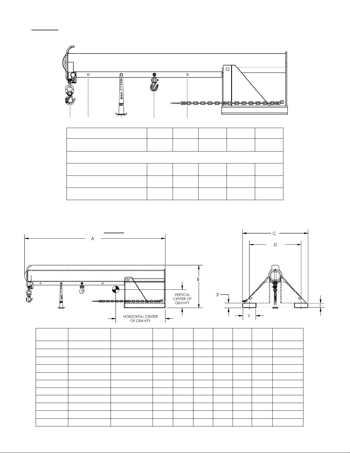
FIG. 1D: LM-1T- 4k, 6k & 8k Centers of Gravity and Maximum Load Ratings for
J I H G F E D C B A
Hook position A B C D E F G H I J
Distance from end of
boom in inches (cm)
Maximum rated load of a load suspended from a single hook located at the corresponding “Hook position”.
LM-1T-3-24
LM-1T-4k
LM-1T-6k
LM-1T-8k
Varying Load Attachment Point and Boom Extension Combinations
36”
91 cm
3000 lb.
1363 kg
4000 lb.
1820 kg
6000 lb.
2727 kg
8000 lb.
3636 kg
48”
122 cm
2750 lb.
1250 kg
3750 lb.
1705 kg
5000 lb.
2272 kg
6650 lb.
3022 kg
60”
152 cm
2500 lb.
1136 kg
3500 lb.
1590 kg
4500 lb.
2045 kg
6000 lb.
2727 kg
72”
183 cm
2250 lb.
1022 kg
3250 lb.
1477 kg
4000 lb.
1820 kg
5300 lb.
2409 kg
84”
213 cm
2000 lb.
909 kg
3000 lb.
1363 kg
3500 lb.
1590 kg
4650 lb.
2113 kg
96”
244 cm
1750 lb.
795 kg
2750 lb.
1250 kg
3000 lb.
1363 kg
4000 lb.
1820 kg
108”
274 cm
1500 lb.
681 kg
2500 lb.
1136 kg
2600 lb.
1181 kg
3500 lb.
1590 kg
120”
305 cm
1250 lb.
568 kg
2250 lb.
1022 kg
2300 lb.
1045 kg
3000 lb.
1363 kg
132”
335 cm
1000 lb.
454 kg
2000 lb.
909 kg
2000 lb.
909 kg
2600 lb.
1181 kg
144”
366 cm
750 lb.
340 kg
1750 lb.
795 kg
1800 lb.
818 kg
2200 lb.
1000 kg
The center of gravity of the boom changes as boom length changes. As shown in the diagram below, the
horizontal center of gravity may be located at any point from RHCG to EHCG:
Retracted horizontal center of gravity (RHCG): boom fully retracted and unloaded. RHCG is measured from
the “origin point” of the above diagram (edges of the fork pockets);
Extended horizontal center of gravity (EHCG): boom fully extended and unloaded. EHCG is also measured
from the “origin point” of the above diagram (edges of the fork pockets);
All other combinations of boom extension and load position produce a horizontal center of gravity located
somewhere between RHCG and EHCG.
FIG. 1E: LM-1T centers of gravity and dimensions
LM-1T-3-24 4813/16” (124 cm) 3211/16 (83 cm) 1313/16” (33.5 cm) 86-1511/4” 13” 32” 24” 257/8” 71/
LM-1T-4-11 51 in. (129.5 cm) 3315/16 in. (86.2 cm) 135/8” (34.6 cm) 86-1531/2” 13” 19” 11” 257/8” 71/
LM-1T-4-24 4813/16 in. (124.0 cm) 3211/16 in. (83.0 cm) 133/
LM-1T-4-30 477/16 in. (120.5 cm) 32 in. (81.3 cm) 1215/16” (32.9 cm) 86-1531/2” 13” 38” 30” 257/8” 71/
LM-1T-4-36 463/16 in. (117.3 cm) 315/16 in. (79.5 cm) 1211/16” (32.2 cm) 86-1531/2” 13” 44” 36” 257/8” 71/
LM-1T-6-11 477/16 in. (120.5 cm) 323/16 in. (81.8 cm) 125/8” (32.1 cm) 86-1531/2” 13” 19” 11” 257/8” 71/
LM-1T-6-24 4511/16 in. (116 cm) 313/16 in. (79.2 cm) 125/16” (31.3 cm) 86-1531/2” 13” 32” 24” 257/8” 71/
LM-1T-6-30 441/2 in. (113 cm) 309/16 in. (77.6 cm) 121/8” (30.8 cm) 86-1531/2” 13” 38” 30” 257/8” 71/
LM-1T-6-36 433/8 in. (110.2 cm) 2915/16 in. (76 cm) 1115/16” (30.3 cm) 86-1531/2” 13” 44” 36” 257/8” 71/
LM-1T-8-24 531/4 in. (135.3 cm) 347/16 in. (87.5 cm) 135/8” (34.6 cm) 845/8-1491/8” 111/2” 32” 24” 269/16” 71/
LM-1T-8-30 531/4 in. (135.3 cm) 347/16 in. (87.5 cm) 135/8” (34.6 cm) 845/8-1491/8” 111/2” 38” 30” 269/16” 71/
LM-1T-8-36 531/4 in. (135.3 cm) 347/16 in. (87.5 cm) 135/8” (34.6 cm) 845/8-1491/8” 111/2” 44” 36” 269/16” 71/
= Center of gravity
Model
Extended horizontal
center of gravity
Copyright 2016 Vestil Manufacturing Co. Page 4 of 28
Retracted horizontal
center of gravity
Vertical center of
gravity
16
A B C D E F G
86-1531/2” 13” 32” 24” 257/8” 71/
2
2
2
2
2
4
4
4
4
4
4
4
21/
21/
21/
21/
21/
21/
21/
21/
21/
21/
21/
21/
2
2
2
2
2
4
4
4
4
4
4
4
Net
weight
434.4 lb.
404.7 lb.
429.3 lb.
447.4 lb.
465.4 lb.
452.7 lb.
477.4 lb.
497.0 lb.
516.5 lb.
665.3 lb.
688.5 lb.
711.7 lb.
Page 5
01/11 rev. 10/26/2017 LM, MANUAL
tem
1
1
1
1
FIG. 1F: LM-1NT-4k Exploded Parts Diagram & Bill of Materials
I
Part No. Description
1
2 08-014-134 Frame, front support leg casting 1
3 08-145-001 Swivel hook, 2-ton 1
4 08-145-041
5 08-145-010
6 99-145-037
7 99-145-084 Lap link 1
8 99-645-019 2-ton hook and shackle 1
9 11211
10 36109 1/2in. – 13 UNC hex nut 1
08-514-319
08-514-128
08-514-320
08-514-321
Weldment, frame, boom/base:
LM-1NT-4-11
LM-1NT-4-24
LM-1NT-4-30
LM-1NT-4-36
5
/16” snap hook
1
/2” 2-ton shackle
5
/16” chain 36” long
/2in. – 13 UNC x 2in. HHCS zinc-
plated bolt
FIG. 1G: LM-1NT-6k Exploded Parts Diagram & Bill of Materials
Item Part No. Description Quantity
08-514-322
1
08-514-129
08-514-323
08-514-324
2 08-014-134
3 08-145-001 Swivel hook, 2-ton 1
4 08-145-002 Swivel hook, 3-ton 1
5 08-145-041
6 08-145-010
7 99-145-019 5/8” 3.25-ton shackle 1
8 99-145-037
9 99-145-084 Lap link 1
10 11211
11 36109 1/2in. – 13 UNC hex nut 1
Weldment, frame, boom/base:
LM-1NT-6-11
LM-1NT-6-24
LM-1NT-6-30
LM-1NT-6-36
Frame, front support leg
casting
5
/16” snap hook
1
/2” 2-ton shackle
5
/16” chain 36” long
/2in. – 13 UNC x 2in. HHCS
zinc-plated bolt
Quantity
1
1
1
1
1
1
1
1
1
1
1
1
1
1
1
1
1
FIG. 1H: LM-1NT-8k Exploded Parts Diagram & Bill of Materials
Item Part No. Description Quantity
08-514-130
1
08-514-317
08-514-318
2 08-014-134
3 08-145-002 Swivel hook, 3-ton 1
4 08-145-005 Swivel hook, 5-ton 1
5 08-145-006 7/8” 6.5-ton shackle 1
6 08-145-041
7 99-145-019 5/8” 3.25-ton shackle 1
8 99-145-037
9 99-145-084 Lap link 1
10 11211
11 36110
Copyright 2016 Vestil Manufacturing Co. Page 5 of 28
Weldment, frame, boom/base:
LM-1NT-8-24
LM-1NT-8-30
LM-1NT-8-36
Frame, front support leg
casting
5
/16” snap hook
5
/16” chain 36” long
/2in. – 13 UNC x 2in. HHCS
zinc-plated bolt
/2” – 13UNC zinc-plated hex
nut
1
1
1
1
1
1
1
1
Page 6
01/11 rev. 10/26/2017 LM, MANUAL
FIG. 1J: LM-1NT- 4k, 6k & 8k Centers of Gravity and Maximum Load Ratings
for Varying Load Attachment Points
HCG
VCG
Center of gravity has both a horizontal component and a vertical component. The vertical center of gravity
(VCG) lies along a horizontal line above the bottom edges of the fork pockets. Similarly, the horizontal center of
gravity (HCG) is located along a vertical line as shown in the diagram below.
E D C B A
Hook position A B C D E
Distance from end of boom in
inches (cm)
Maximum rated load of a load suspended from a single hook located at the
corresponding “Hook position”.
LM-1NT-4k
LM-1NT-6k
LM-1NT-8k
FIG. 1K: LM-1NT centers of gravity and dimensions
36”
91 cm
4000 lb.
1820 kg
6000 lb.
2727 kg
8000 lb.
3636 kg
48”
122 cm
3750 lb.
1705 kg
5000 lb.
2272 kg
6650 lb.
3022 kg
60”
152 cm
3500 lb.
1590 kg
4500 lb.
2045 kg
6000 lb.
2727 kg
72”
183 cm
3250 lb.
1477 kg
4000 lb.
1820 kg
5300 lb.
2409 kg
84”
213 cm
3000 lb.
1363 kg
3500 lb.
1590 kg
4850 lb.
2205 kg
Model
LM-1NT-4-11 2811/16” (72.9 cm) 1013/16” (27.5 cm) 811/2” 2711/16” 19” 11” 71/2” 21/2” 309.9 lb.
LM-1NT-4-24 2811/16” (72.9 cm) 1013/16” (27.5 cm) 811/2” 2413/16” 32” 24” 71/2” 21/2” 334.6 lb.
LM-1NT-4-30 2811/16” (72.9 cm) 1013/16” (27.5 cm) 811/2” 2413/16” 38” 30” 71/2” 21/2” 352.6 lb.
LM-1NT-4-36 2811/16” (72.9 cm) 1013/16” (27.5 cm) 811/2” 2413/16” 44” 36” 71/2” 21/2” 370.6 lb.
LM-1NT-6-11 27” (68.6cm) 1013/16” (27.5 cm) 811/2” 2413/16” 19” 11” 71/4” 21/4” 357.7 lb.
LM-1NT-6-24 27” (68.6cm) 1013/16” (27.5 cm) 811/2” 2413/16” 32” 24” 71/4” 21/4” 382.4 lb.
LM-1NT-6-30 27” (68.6cm) 1013/16” (27.5 cm) 811/2” 2413/16” 38” 30” 71/4” 21/4” 402.0 lb.
LM-1NT-6-36 27” (68.6cm) 1013/16” (27.5 cm) 811/2” 2413/16” 44” 36” 71/4” 21/4” 421.5 lb.
LM-1NT-8-24 301/8” (29.8 cm) 113/4” (29.8 cm) 801/8” 231/2” 32” 24” 71/4” 21/4” 488.4 lb.
LM-1NT-8-30 301/8” (29.8 cm) 113/4” (29.8 cm) 801/8” 231/2” 38” 30” 71/4” 21/4” 506.9 lb.
LM-1NT-8-36 301/8” (29.8 cm) 113/4” (29.8 cm) 801/8” 231/2” 44” 36” 71/4” 21/4” 525.4 lb.
Copyright 2016 Vestil Manufacturing Co. Page 6 of 28
Horizontal center
of gravity
Vertical center of
gravity
A B C D E F Net weight
Page 7
01/11 rev. 10/26/2017 LM, MANUAL
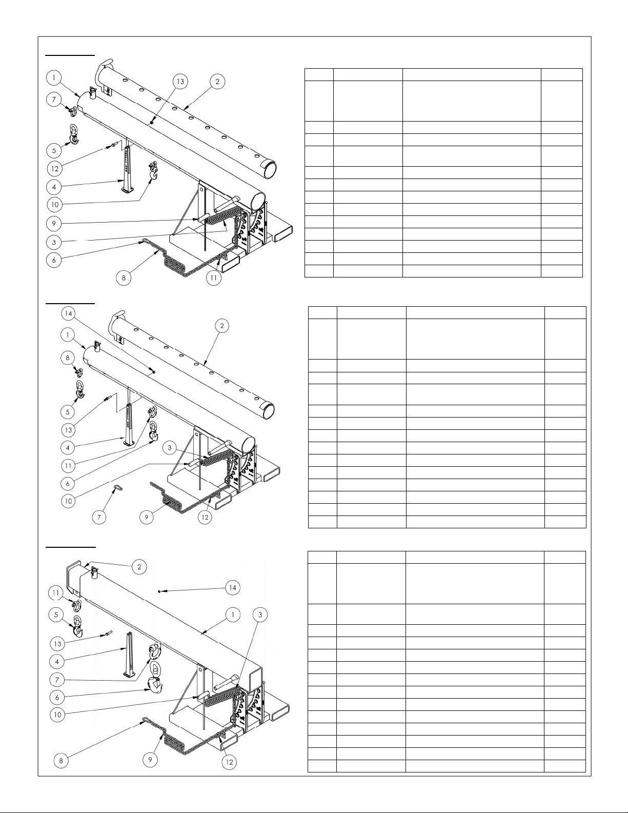
FIG. 2A: LM-OBT-3-24 & LM-OBT-4k Exploded Parts Diagram & Bill of Materials
Item Part No. Description Quantity
08-514-119
1
08-514-298
08-514-299
2 08-514-293 Weldment, inner tube 1
3 01-146-006 Spring 1
4 08-014-069-001
5 08-145-001 Swivel hook, 2-ton 1
6 08-145-041 5/16” snap hook 1
7 08-145-010 1/2” 2-ton shackle 1
8 08-645-008 Boom chain and pin 1
9 13-025-023 11/8” i.d. red handle grip 1
10 99-645-019 2-ton hook and shackle 1
11 99-145-084 Lap link 1
12 11210 1/2” – 13UNC x 13/4” hex bolt 1
13 36110 1/2” – 13UNC zinc-plated hex nut 1
Weldment, frame, boom + base:
LM-OBT-4k-24 & LM-OBT-3-24
LM-OBT-4k-30
LM-OBT-4k-36
Frame, front supporting leg (small)
casting
FIG. 2B: LM-OBT-6k Exploded Parts Diagram & Bill of Materials
Item
1
2 08-514-293 Weldment, inner tube 1
3 01-146-006 Spring 1
4 08-014-069-001
5 08-145-001 Swivel hook, 2-ton 1
6 08-145-002 Swivel hook, 3-ton 1
7 08-145-041 5/16” snap hook 1
8 08-145-010 1/2” 2-ton shackle 1
9 08-645-008 Boom chain and pin 1
10 13-025-023 11/8” i.d. red handle grip 1
11 99-145-019 2-ton hook and shackle 1
12 99-145-084 Lap link 1
13 11210 1/2” – 13UNC x 13/4” hex bolt 1
14 36110 1/2” – 13UNC zinc-plated hex nut 1
Part No. Description Quantity
08-514-122
08-514-300
08-514-301
Weldment, frame, boom + base:
LM-OBT-6k-24
LM-OBT-6k-30
LM-OBT-6k-36
Frame, front supporting leg (small)
casting
FIG. 2C: LM-OBT-8k Exploded Parts Diagram & Bill of Materials
Item
1
2 08-014-069-001
3 08-514-310 Weldment, inner tube 1
4 01-146-006 Spring 2
5 08-145-002 Swivel hook, 3-ton 1
6 08-145-005 Swivel hook, 5-ton 1
7 08-145-006 7/8” 6.5-ton shackle 1
8 08-145-041 5/16” snap hook 1
9 08-645-008 Boom chain and pin 1
10 13-025-023 11/8” i.d. red handle grip 1
11 99-145-019 2-ton hook and shackle 1
12 99-145-084 Lap link 1
13 11211 1/2” – 13UNC x 2” hex bolt 1
14 36110 1/2” – 13UNC zinc-plated hex nut 1
Part No. Description Quantity
08-514-125
08-514-311
08-514-312
Weldment, frame, boom + base:
LM-OBT-8k-24
LM-OBT-8k-30
LM-OBT-8k-36
Frame, front supporting leg (small)
casting
1
1
1
1
1
1
1
1
1
1
1
1
Copyright 2016 Vestil Manufacturing Co. Page 7 of 28
Page 8
01/11 rev. 10/26/2017 LM, MANUAL
Load Attachment Point and
Boom Extension Combinations
” (36.4 cm)
”
” (36.4 cm)
”
” (35.4 cm)
”
” (34.8 cm)
”
” (33.8 cm)
”
” (33.2 cm)
”
” (32.5 cm)
”
cm)
”
cm)
”
cm)
”
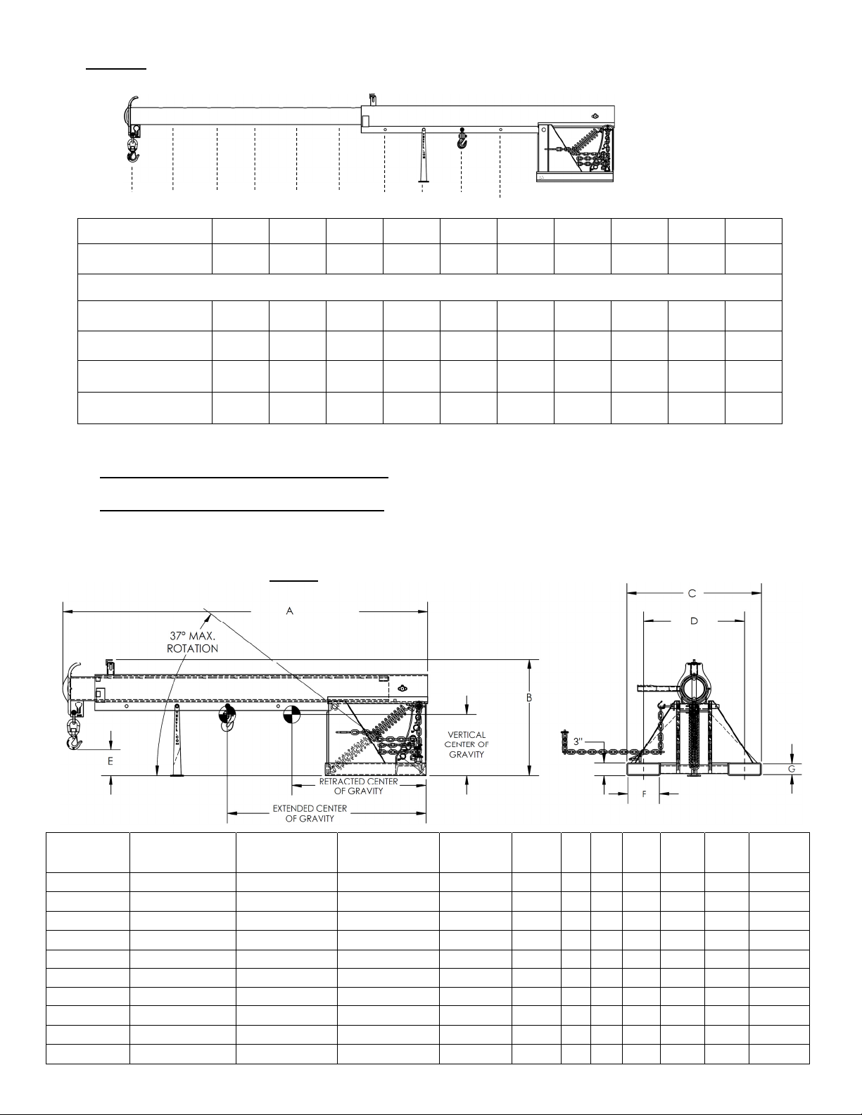
FIG. 2D: LM-OBT- 4k, 6k & 8k Centers of Gravity and Maximum Load Ratings for Varying
J I H G F E D C B A
Hook position A B C D E F G H I J
Distance from mast
end of boom
Maximum rated load of a load suspended from a single hook located at the corresponding “Hook position”.
LM-OBT-3-24
LM-OBT-4k
LM-OBT-6k
LM-OBT-8k
36”
91 cm
3000 lb.
1363 kg
4000 lb.
1820 kg
6000 lb.
2727 kg
8000 lb.
3636 kg
48”
122 cm
2750 lb.
1250 kg
3750 lb.
1705 kg
5000 lb.
2272 kg
6650 lb.
3022 kg
60”
152 cm
2500 lb.
1136 kg
3500 lb.
1590 kg
4500 lb.
2045 kg
6000 lb.
2727 kg
72”
183 cm
2250 lb.
1022 kg
3250 lb.
1477 kg
4000 lb.
1820 kg
5300 lb.
2409 kg
84”
213 cm
2000 lb.
909 kg
3000 lb.
1363 kg
3500 lb.
1590 kg
4650 lb.
2113 kg
96”
244 cm
1750 lb.
795 kg
2750 lb.
1250 kg
3000 lb.
1364 kg
4000 lb.
1820 kg
108”
274 cm
1500 lb.
681 kg
2500 lb.
1136 kg
2600 lb.
1182 kg
3500 lb.
1590 kg
120”
305 cm
1250 lb.
568 kg
2250 lb.
1023 kg
2300 lb.
1045 kg
3000 lb.
1363 kg
132”
335 cm
1000 lb.
454 kg
2000 lb.
909 kg
2000 lb.
909 kg
2600 lb.
1181 kg
366 cm
750 lb.
340 kg
1750 lb.
795 kg
1800 lb.
818 kg
2200 lb.
1000 kg
The center of gravity of the boom changes as boom length changes. As shown in the diagram below, the horizontal
center of gravity may be located at any point from RHCG to EHCG:
Retracted horizontal center of gravity (RHCG): boom fully retracted and unloaded. RHCG is measured from the
“origin point” of the above diagram (edges of the fork pockets);
Extended horizontal center of gravity (EHCG): boom fully extended and unloaded. EHCG is also measured from
the “origin point” of the above diagram (edges of the fork pockets);
All other combinations of boom extension and load position produce a horizontal center of gravity located
somewhere between RHCG and EHCG.
FIG. 2E: LM-OBT centers of gravity and dimensions
144”
Model
LM-OBT-3-24 47” (119.4 cm) 323/8” (82.2 cm) 145/
LM-OBT-4-24 47” (119.4 cm) 323/8” (82.2 cm) 145/
LM-OBT-4-30 4513/16” (116.4 cm) 313/4” (80.6 cm) 1315/
LM-OBT-4-36 4411/16” (113.5 cm) 313/16” (79.2 cm) 1311/
LM-OBT-6-24 441/16” (112 cm) 3015/16” (78.6 cm) 135/
LM-OBT-6-30 43” (109.2 cm) 303/8” (77.2 cm) 131/
LM-OBT-6-36 42” (106.7 cm) 2913/16” (75.7 cm) 1213/
LM-OBT-8-24 5111/16” (131.3 cm) 35” (88.9 cm) 151/4” (38.7
LM-OBT-8-30 5111/16” (131.3 cm) 35” (88.9 cm) 151/4” (38.7
LM-OBT-8-36 5111/16” (131.3 cm) 35” (88.9 cm) 151/4” (38.7
Extended
horizontal center
of gravity
Copyright 2016 Vestil Manufacturing Co. Page 8 of 28
Retracted
horizontal center
of gravity
Vertical center of
gravity
16
16
16
16
16
16
16
A B C D E F G
865/8”-1465/8” 2711/
865/8”-1465/8” 2711/
865/8”-1465/8” 2711/
865/8”-1465/8” 2711/
865/8”-1465/8” 2711/
865/8”-1465/8” 2711/
865/8”-1465/8” 2711/
851/4”-1451/4” 287/8” 32” 24” 51/
851/4”-1451/4” 287/8” 38” 30” 51/
851/4”-1451/4” 287/8” 44” 36” 51/
32” 24” 6” 71/2” 21/2” 436.7 lb.
16
32” 24” 6” 71/2” 21/2” 433.9 lb.
16
38” 30” 6” 71/2” 21/2” 451.5 lb.
16
44” 36” 6” 71/2” 21/2” 469.1 lb.
16
32” 24” 6” 71/4” 21/4” 481.9 lb.
16
38” 30” 6” 71/4” 21/4” 501.1 lb.
16
44” 36” 6” 71/4” 21/4” 520.3 lb.
16
71/4” 21/4” 665.0 lb.
8
71/4” 21/4” 684.1 lb.
8
71/4” 21/4” 703.3 lb.
8
Net
weight
Page 9
01/11 rev. 10/26/2017 LM, MANUAL
5
1
5
1
1
7
5
5
1
1
FIG. 2F: LM-OBNT-4k Exploded Parts Diagram & Bill of Materials
Item Part No. Description Quantity
08-514-132
1
08-514-302
08-514-303
2 01-146-006 Spring 1
3 08-014-069-001 Frame, front support leg (small) casting
4 08-145-001 Swivel hook, 2-ton 1
5 08-145-041
6 08-145-010
7 08-645-008 Assembly, boom chain and pin 1
8 13-025-023
9 99-145-084 Lap link 1
10 99-645-019 2-ton hook and shackle 1
11 11210
12 36110
Weldment, frame, boom + base
LM-OBNT-4-24
LM-OBNT-4-30
LM-OBNT-4-36
5
/16” snap hook
1
/2” 2-ton shackle
11/8” inner diameter red handle grip
1
/2” – 13UNC x 13/4” hex bolt
1
/2” – 13 zinc-plated hex nut
FIG. 2G: LM-OBNT-6k Exploded Parts Diagram & Bill of Materials
1
1
1
1
1
1
1
1
1
Item Part No. Description Quantity
08-514-134
1
08-514-304
08-514-305
2 01-146-006 Spring 1
3 08-014-069-001 Frame, front support leg (small) casting
4 08-145-001 Swivel hook, 2-ton 1
5 08-145-002 Swivel hook, 3-ton 1
6 08-145-041
7 08-145-010
8 08-645-008 Assembly, boom chain and pin 1
9 13-025-023
10 99-145-019
11 99-145-084 Lap link 1
12 11210
13 36110
Weldment, frame, boom + base
LM-OBNT-6-24
LM-OBNT-6-30
LM-OBNT-6-36
/16” snap hook
/2” 2-ton shackle
11/8” inner diameter red handle grip
/8” 31/4-ton shackle
/2” – 13UNC x 13/4” hex bolt
/2” – 13 zinc-plated hex nut
FIG. 2H: LM-OBNT-8k Exploded Parts Diagram & Bill of Materials
Item Part No. Description Quantity
08-514-136
1
08-514-308
08-514-309
2 01-146-006 Spring 2
3 08-014-069-001 Frame, front support leg (small) casting
4 08-145-006
5 08-145-002 Swivel hook, 3-ton 1
6 08-145-041
7 08-145-005
8 08-645-008 Assembly, boom chain and pin 1
9 13-025-023
10 99-145-019
11 99-145-084 Lap link 1
12 11211
13 36110
Weldment, frame, boom + base
LM-OBNT-8-24
LM-OBNT-8-30
LM-OBNT-8-36
/8” 61/2-ton shackle
/16” snap hook
Swivel hook, 5-ton
11/8” inner diameter red handle grip
/8” 31/4-ton shackle
/2” – 13UNC x 2” hex bolt
/2” – 13 zinc-plated hex nut
1
1
1
1
1
1
1
1
1
1
1
1
1
1
1
1
1
1
1
1
1
Copyright 2016 Vestil Manufacturing Co. Page 9 of 28
Page 10

01/11 rev. 10/26/2017 LM, MANUAL
FIG. 2J: LM-OBNT- 4k, 6k & 8k Centers of Gravity and Maximum Load
Ratings for Varying Load Attachment Points
Center of gravity has both a horizontal component and a vertical component. The vertical center of gravity
(VCG) lies along a horizontal line above the bottom edges of the fork pockets. Similarly, the horizontal center of
gravity (HCG) is located along a vertical line as shown in the diagram below.
E D C B A
Hook position A B C D E
Distance from end of boom in
inches (cm)
Maximum rated load of a load suspended from a single hook located at the
corresponding “Hook position”.
LM-OBNT-4k
LM-OBNT-6k
LM-OBNT-8k
FIG. 2K: LM-OBNT centers of gravity and dimensions
36”
91 cm
4000 lb.
1820 kg
6000 lb.
2727 kg
8000 lb.
3636 kg
48”
122 cm
3750 lb.
1705 kg
5000 lb.
2272 kg
6650 lb.
3022 kg
60”
152 cm
3500 lb.
1590 kg
4500 lb.
2045 kg
6000 lb.
2727 kg
72”
183 cm
3250 lb.
1477 kg
4000 lb.
1820 kg
5300 lb.
2409 kg
3000 lb.
1363 kg
3500 lb.
1590 kg
4850 lb.
2205 kg
78”
198 cm
Model
LM-1NT-4-24 263/4” (67.9 cm) 115/8” (29.5 cm) 807/8” 265/8” 32” 24” 51/2” 71/2” 21/2” 339.2 lb.
LM-1NT-4-30 263/4” (67.9 cm) 115/8” (29.5 cm) 807/8” 265/8” 38” 30” 51/2” 71/2” 21/2” 356.9 lb.
LM-1NT-4-36 263/4” (67.9 cm) 115/8” (29.5 cm) 807/8” 265/8” 44” 36” 51/2” 71/2” 21/2” 374.4 lb.
LM-1NT-6-24 263/4” (67.9 cm) 115/8” (29.5 cm) 807/8” 265/8” 32” 24” 51/2” 71/4” 21/4” 387.0 lb.
LM-1NT-6-30 263/4” (67.9 cm) 115/8” (29.5 cm) 807/8” 265/8” 38” 30” 51/2” 71/4” 21/4” 406.2 lb.
LM-1NT-6-36 263/4” (67.9 cm) 115/8” (29.5 cm) 807/8” 265/8” 44” 36” 51/2” 71/4” 21/4” 425.4 lb.
LM-1NT-8-24 301/4” (76.8 cm) 133/16” (33.5 cm) 791/2” 251/8” 32” 24” 411/16” 71/4” 21/4” 490.9 lb.
LM-1NT-8-30 301/4” (76.8 cm) 133/16” (33.5 cm) 791/2” 251/8” 38” 30” 411/16” 71/4” 21/4” 510.0 lb.
LM-1NT-8-36 301/4” (76.8 cm) 133/16” (33.5 cm) 791/2” 251/8” 44” 36” 411/16” 71/4” 21/4” 521.2 lb.
Horizontal
center of gravity
Vertical center
of gravity
A B C D E F G
Net
weight
Copyright 2016 Vestil Manufacturing Co. Page 10 of 28
Page 11

01/11 rev. 10/26/2017 LM, MANUAL
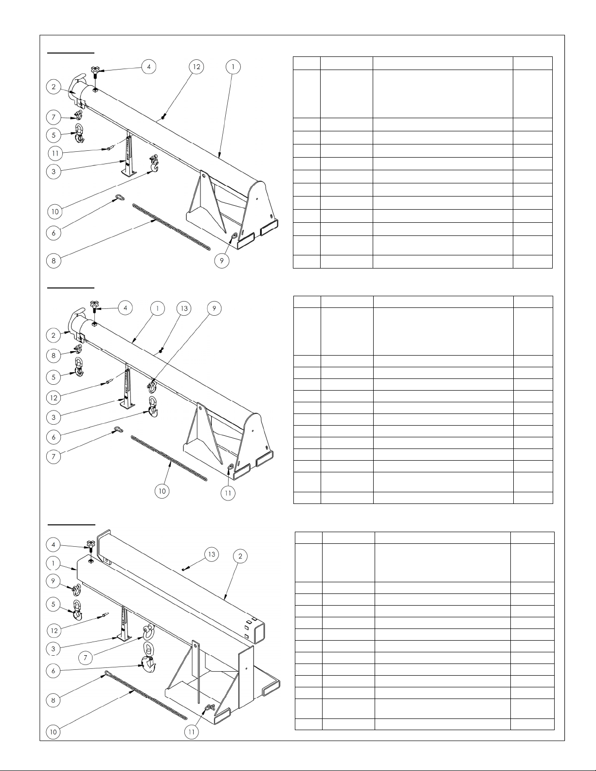
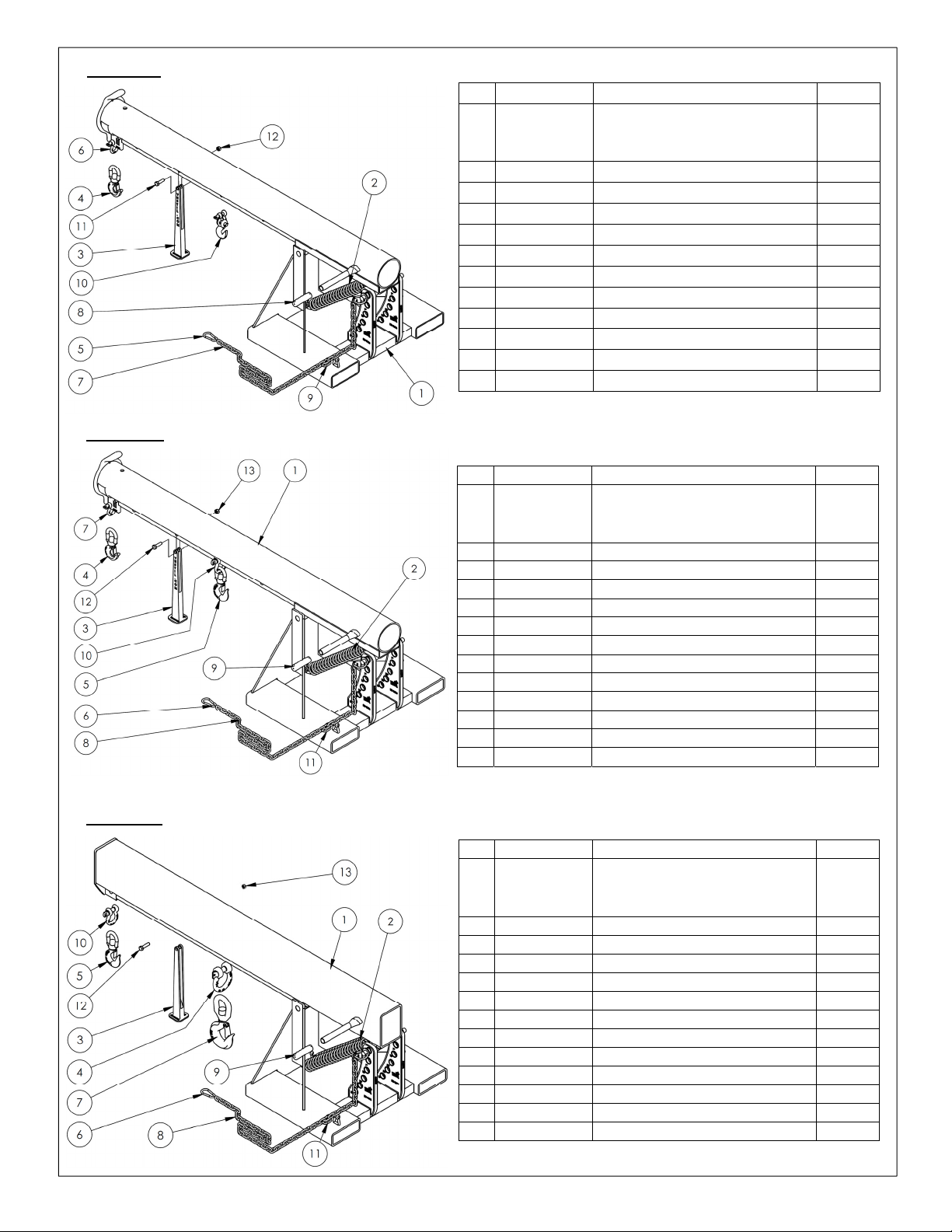
FIG. 3A: LM-HRT-4k Exploded Parts Diagram & Bill of Materials
Item Part No. Description Quantity
08-514-005
1
08-514-337
08-514-339
2 08-025-004 X-handle, locking bolt 1
3 08-145-001 Swivel hook, 2-ton 1
4 08-145-010 1/2in. 2-ton shackle 1
5 08-145-041 5/16in. snap hook 1
6 99-145-037 5/16in. x 36in. chain 1
7 99-145-084 Lap link 1
8 99-645-019 2-ton hook and shackle 1
Assembly, frame, boom
LM-HRT-4k 24
LM-HRT-4k-30
LM-HRT-4k-36
1
1
1
FIG. 3B: LM-HRT-6k Exploded Parts Diagram & Bill of Materials
Item Part No. Description Quantity
08-514-006
1
08-514-338
08-514-340
2 08-025-004 X-handle, locking bolt 1
3 08-145-001 Swivel hook, 2-ton 1
4 08-145-002 Swivel hook, 3-ton 1
5 08-145-010 1/2” 2-ton shackle 1
6 08-145-041 5/16” snap hook 1
7 99-145-019 5/8” 31/4-ton hook and shackle 1
8 99-145-037 5/16’ x 36” chain 1
9 99-145-084 Lap link 1
Assembly, frame, boom
LM-HRT-6k 24
LM-HRT-6k-30
LM-HRT-6k-36
1
1
1
Copyright 2016 Vestil Manufacturing Co. Page 11 of 28
Page 12

01/11 rev. 10/26/2017 LM, MANUAL
” (98.3 cm)
”
”
”
” (94.8 cm)
”
”
”
” (93.5 cm)
”
”
”
” (93.5 cm)
”
”
”
” (92.3 cm)
”
”
”
”
”
”
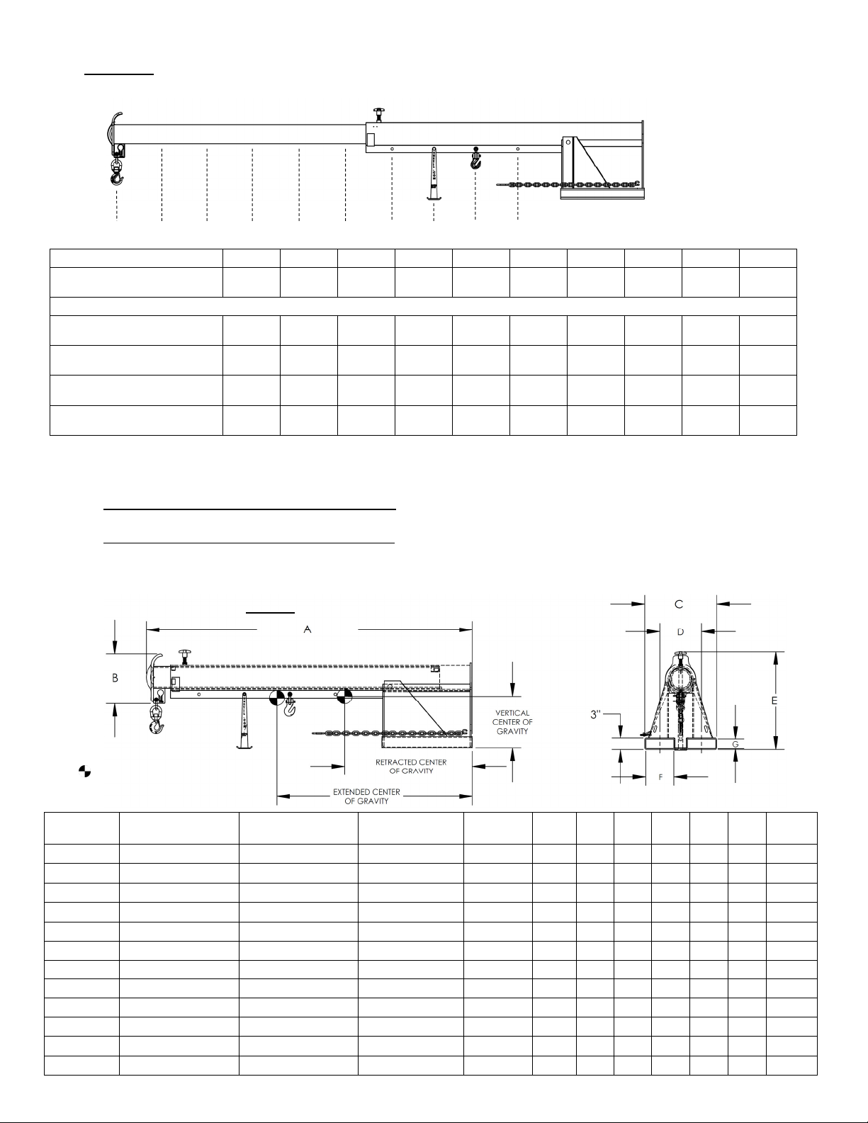
FIG. 3C: LM-HRT- 4k & 6k Centers of Gravity and Maximum Load Ratings for
Varying Load Attachment Point and Boom Extension Combinations
K J I H G F E D C B A
Hook position A B C D E F G H I J K
Distance from end
of boom
Maximum rated load of a load suspended from a single hook located at the corresponding “Hook position”.
LM-HRT-4-24
LM-HRT-6-24
The center of gravity of the boom changes as boom length changes. As shown in the diagram below, the horizontal center of
gravity may be located at any point from RHCG to EHCG:
Retracted horizontal center of gravity (RHCG): boom fully retracted and unloaded. RHCG is measured from the “origin point”
of the above diagram (edges of the fork pockets);
Extended horizontal center of gravity (EHCG): boom fully extended and unloaded. EHCG is also measured from the “origin
point” of the above diagram (edges of the fork pockets);
All other combinations of boom extension and load position produce a horizontal center of gravity located somewhere between
RHCG and EHCG.
30”
76 cm
4000 lb.
1820 kg
6000 lb.
2727 kg
36”
91 cm
3750 lb.
1705 kg
5000 lb.
2273 kg
42”
107 cm
3500 lb.
1590 kg
4500 lb.
2046 kg
48”
122 cm
3250 lb.
1477 kg
4000 lb.
1818 kg
54”
137 cm
3000 lb.
1363 kg
3500 lb.
1591 kg
60”
152 cm
2750 lb.
1250 kg
3000 lb.
1363 kg
66”
168 cm
2500 lb.
1136 kg
2600 lb.
1182 kg
FIG. 3D: LM-HRT centers of gravity and dimensions
72”
183 cm
2250 lb.
1022 kg
2300 lb.
1046 kg
78”
198 cm
2000 lb.
909 kg
2000 lb.
909 kg
84”
213 cm
1750 lb.
796 kg
1800 lb.
818 kg
90”
229 cm
1500 lb.
682 kg
1550 lb.
705 kg
Model
LM-HRT-4-24 133/16” (33.5 cm) 10” (25.4 cm) 3811/
LM-HRT-4-30 131/8” (33.3 cm) 101/4” (26 cm) 375/
LM-HRT-4-36 131/16” (33.2 cm) 101/4” (26 cm) 3613/
LM-HRT-6-24 133/16” (33.5 cm) 103/8” (26.4 cm) 3613/
LM-HRT-6-30 131/8” (33.3 cm) 103/8” (26.4 cm) 365/
LM-HRT-6-36 131/8” (33.3 cm) 103/8” (26.4 cm) 3513/16” (91 cm) 547/8”-947/8” 13” 44” 36” 71/
Extended
horizontal center
of gravity
Retracted
horizontal center
of gravity
Vertical center of
gravity
16
16
16
16
16
A B C D E F G
547/8”-947/8” 13” 32” 24” 71/
547/8”-947/8” 13” 38” 30” 71/
547/8”-947/8” 13” 44” 36” 71/
547/8”-947/8” 13” 32” 24” 71/
547/8”-947/8” 13” 38” 30” 71/
21/
21/
21/
21/
21/
21/
7913/
2
7913/
2
7913/
2
7913/
4
7913/
4
7913/
4
2
2
2
4
4
4
16
16
16
16
16
16
Net
weight
943.7 lb.
958.9 lb.
974.1 lb.
978.2 lb.
993.4 lb.
1008.6 lb.
Copyright 2016 Vestil Manufacturing Co. Page 12 of 28
Page 13

01/11 rev. 10/26/2017 LM, MANUAL
FIG. 3E: LM-HRNT-4k Exploded Parts Diagram & Bill of Materials
Item Part No. Description Quantity
08-514-007
1
08-514-341
08-514-343
2 08-145-001 2-ton hook 1
3 08-145-010 Specialty hardware: 2-ton shackle 1
4 08-145-041 5/16in. snap hook 1
5 99-145-037 5/16in. x 36in. chain 1
6 99-145-084 Lap link 1
7 99-645-019 2-ton hook and shackle 1
Frame, boom + base weldment:
LM-HRNT-4-24
LM-HRNT-4-30
LM-HRNT-4-36
1
1
1
FIG. 3F: LM-HRNT-6k Exploded Parts Diagram & Bill of Materials
Item Part No. Description Quantity
1 08-145-001 Swivel hook, 2-ton 1
2 08-145-010 1/2” 2-ton shackle 1
3 08-145-041 5/16” snap hook 1
4 99-145-037 5/16” chain 36” long 1
5 99-145-084 Lap Link 1
08-514-008
6
08-514-342
08-514-344
7 08-145-002 Swivel hook, 3-ton 1
8 99-145-019 5/8” 31/4-ton shackle 1
Frame, boom + base weldment:
LM-HRNT-6-24
LM-HRNT-6-30
LM-HRNT-6-36
1
1
1
Copyright 2016 Vestil Manufacturing Co. Page 13 of 28
Page 14

01/11 rev. 10/26/2017 LM, MANUAL
cm)
”
”
cm)
”
”
cm)
”
”
cm)
”
”
cm)
”
”
cm)
”
”
FIG. 3G: LM-HRNT- 4k & 6k Centers of Gravity and Maximum Load Ratings for
Varying Load Attachment Points
Hook position A B C D
Distance from end of boom in
inches (cm)
Maximum rated load in pounds (kg) of a load suspended from a single
hook located at the corresponding “Hook position”.
LM-HRNT-4k
LM-HRNT-6k
30”
76 cm
4000 lb.
1820 kg
6000 lb.
2727 kg
36”
91 cm
3750 lb.
1705 kg
5000 lb.
2045 kg
42”
107 cm
3500 lb.
1590 kg
4500 lb.
1727 kg
48”
122 cm
3250 lb.
1477 kg
4000 lb.
1363 kg
Center of gravity has both a horizontal component and a vertical component. The vertical center of gravity
(VCG) lies along a line 38 inches (~97 cm) from the bottom edges of the fork pockets. Similarly, the horizontal
center of gravity (HCG) is located 8 inches (~20cm) from the front edge of the vertical support.
D C B A
Model
LM-HRNT-4-24 85/8” (21.9 cm) 2811/16” (72.9
LM-HRNT-4-30 85/8” (21.9 cm) 2811/16” (72.9
LM-HRNT-4-36 85/8” (21.9 cm) 2811/16” (72.9
LM-HRNT-6-24 813/16” (22.4 cm) 277/8” (68.9
LM-HRNT-6-30 813/16” (22.4 cm) 277/8” (68.9
LM-HRNT-6-36 813/16” (22.4 cm) 277/8” (68.9
Copyright 2016 Vestil Manufacturing Co. Page 14 of 28
Horizontal center
of gravity
Vertical center of
gravity
A B C D E F G
503/8” 131/4” 32” 24” 71/
503/8” 131/4” 38” 30” 71/
503/8” 131/4” 44” 36” 71/
503/8” 131/4” 32” 24” 71/
503/8” 131/4” 38” 30” 71/
503/8” 131/4” 44” 36” 71/
21/
2
2
2
4
4
4
789/16” 882.3 lb.
2
21/
789/16” 897.5 lb.
2
21/
789/16” 912.7 lb.
2
21/
789/16” 916.6 lb.
4
21/
789/16” 931.8 lb.
4
21/
789/16” 947.0 lb.
4
Net
weight
Page 15

01/11 rev. 10/26/2017 LM, MANUAL
FIG. 4A: LM-EBT-4k Exploded Parts Diagram & Bill of Materials
Item Part No. Description Quantity
08-514-169
1
08-514-263
08-514-170
08-514-171
2 08-514-261 Weldment, inner tube/boom: 1
3 08-025-004 X-handle, locking bolt 1
4 08-145-041
5 99-145-084 Lap link 1
6 99-145-037
7 08-145-001 Swivel hook, 2-ton 1
8 08-145-010
9 99-645-019 2-ton hook-and-shackle 1
Weldment, frame, base:
LM-EBT-4-11
LM-EBT-4-24
LM-EBT-4-30
LM-EBT-4-36
5
/16” snap hook
5
/16” chain 36” long
1
/2” 2-ton shackle
FIG. 4B: LM-EBT-6k Exploded Parts Diagram & Bill of Materials
FIG. 4C: LM-EBT-8k Exploded Parts Diagram & Bill of Materials
Item Part No. Description Quantity
08-514-172
1
08-514-265
08-514-173
08-514-174
2 08-514-261 Weldment, inner tube/boom: 1
3 08-025-004 X-handle, locking bolt 1
4 08-145-041
5 99-145-084 Lap link 1
6 99-145-037
7 08-145-001 Swivel hook, 2-ton 1
8 08-145-010
9 08-145-002 Swivel hook, 3-ton 1
10 99-145-019
Weldment, frame, base:
LM-EBT-6-11
LM-EBT-6-24
LM-EBT-6-30
LM-EBT-6-36
5
/16” snap hook
5
/16” chain 36” long
1
/2” 2-ton shackle
5
/8” 31/4-ton shackle
Item Part No. Description Quantity
08-514-274
1
08-514-281
08-514-282
2 08-514-272 Weldment, inner tube/boom: 1
3 08-025-004 X-handle, locking bolt 1
4 08-145-041
5 99-145-084 Lap link 1
6 99-145-037
7 99-145-019
8 08-145-002 Swivel hook, 3-ton 1
9 08-145-006
10 08-145-005 Swivel hook, 5-ton 1
Weldment, frame, base:
LM-EBT-8-24
LM-EBT-8-30
LM-EBT-8-36
5
/16” snap hook
5
/16” chain 36” long
5
/8” 31/4-ton shackle
7
/8” 61/2-ton shackle
1
1
1
1
1
1
1
1
1
1
1
1
1
1
1
1
1
1
1
1
1
1
Copyright 2016 Vestil Manufacturing Co. Page 15 of 28
Page 16

01/11 rev. 10/26/2017 LM, MANUAL
”
”
”
”
”
”
”
”
”
”
”
”
”
”
”
”
”
”
”
”
”
”
FIG. 4D: LM-EBT – 4k, 6k & 8k Centers of Gravity and Maximum Load Ratings
for Varying Load Attachment Point and Boom Extension Combinations
J I H G F E D C B A
Hook position A B C D E F G H I J
Distance from end
of boom in inches
(cm)
Maximum rated load of a load suspended from a single hook located at the corresponding “Hook position”.
LM-EBT-4k
LM-EBT-6k
LM-EBT-8k
The center of gravity of the boom changes as boom length changes. As shown in the diagram below, the
horizontal center of gravity may be located at any point from RHCG to EHCG:
Retracted horizontal center of gravity (RHCG): boom fully retracted and unloaded. RHCG is measured from the
“origin point” of the above diagram (edges of the fork pockets);
Extended horizontal center of gravity (EHCG): boom fully extended and unloaded. EHCG is also measured from the
“origin point” of the above diagram (edges of the fork pockets);
All other combinations of boom extension and load position produce a horizontal center of gravity located
somewhere between RHCG and EHCG.
36”
91 cm
4000 lb.
1820 kg
6000 lb.
2727 kg
8000 lb.
3636 kg
48”
122 cm
3750 lb.
1705 kg
5000 lb.
2273 kg
6650 lb.
3022 kg
60”
152 cm
3500 lb.
1590 kg
4500 lb.
2046 kg
6000 lb.
2727 kg
72”
183 cm
3250 lb.
1477 kg
4000 lb.
1818 kg
5300 lb.
2409 kg
84”
213 cm
3000 lb.
1363 kg
3500 lb.
1591 kg
4650 lb.
2113 kg
96”
244 cm
2750 lb.
1250 kg
3000 lb.
1363 kg
4000 lb.
1820 kg
108”
274 cm
2500 lb.
1136 kg
2600 lb.
1182 kg
3500 lb.
1590 kg
120”
305 cm
2250 lb.
1022 kg
2300 lb.
1046 kg
3000 lb.
1363 kg
132”
335 cm
2000 lb.
909 kg
2000 lb.
909 kg
2600 lb.
1181 kg
144”
366 cm
1750 lb.
796 kg
1800 lb.
818 kg
2200 lb.
1000 kg
FIG. 4E: LM-EBT centers of gravity and dimensions
Model
LM-EBT-4-11 581/16” (147.5 cm) 371/2” (95.2 cm) 51/16” (12.9 cm) 861/4-1533/4” 13” 19” 11” 71/
LM-EBT-4-24 553/16” (140.2 cm) 365/16” (92.2 cm) 47/16” (11.3 cm) 861/4-1533/4” 13” 32” 24” 71/
LM-EBT-4-30 541/8” (137.5 cm) 355/16” (89.7 cm) 41/2” (11.4 cm) 861/4-1533/4” 13” 38” 30” 71/
LM-EBT-4-36 527/8” (134.3 cm) 349/16” (87.8 cm) 41/2” (11.4 cm) 861/4-1533/4” 13” 44” 36” 71/
LM-EBT-6-11 543/16” (137.6 cm) 3511/16” (90.6 cm) 413/16” (12.2 cm) 861/4-1533/4” 13” 19” 11” 71/
LM-EBT-6-24 525/16” (132.9 cm) 347/16” (87.5 cm) 41/8” (10.5 cm) 861/4-1533/4” 13” 32” 24” 71/
LM-EBT-6-30 5015/16” (129.4 cm) 3313/16” (85.9 cm) 41/4” (10.8 cm) 861/4-1533/4” 13” 38” 30” 71/
LM-EBT-6-36 497/8” (126.7 cm) 331/4” (84.5 cm) 43/16” (10.6 cm) 861/4-1533/4” 13” 44” 36” 71/
LM-EBT-8-24 571/8” (145.1 cm) 38” (96.5 cm) 413/16” (12.2 cm) 847/8-1493/8” 111/2” 32” 24” 71/
LM-EBT-8-30 571/8” (145.1 cm) 38” (96.5 cm) 413/16” (12.2 cm) 847/8-1493/8” 111/2” 38” 30” 71/
LM-EBT-8-36 571/8” (145.1 cm) 38” (96.5 cm) 413/16” (12.2 cm) 847/8-1493/8” 111/2” 44” 36” 71/
Extended horizontal
center of gravity
Retracted horizontal
center of gravity
Vertical center of
gravity
A B C D E F
Net
weight
21/
21/
21/
21/
21/
21/
21/
21/
21/
21/
21/
2
2
2
2
4
4
4
4
4
4
4
335.9 lb.
354.0 lb.
367.0 lb.
377.9 lb.
368.7 lb.
386.8 lb.
403.6 lb.
414.6 lb.
606.3 lb.
621.2 lb.
635.8 lb.
2
2
2
2
4
4
4
4
4
4
4
Copyright 2016 Vestil Manufacturing Co. Page 16 of 28
Page 17

01/11 rev. 10/26/2017 LM, MANUAL
FIG. 4F: LM-EBNT-4k Exploded Parts Diagram & Bill of Materials
Item Part No. Description Quantity
Weldment, frame, boom/base:
08-514-287
1
08-514-003
08-514-288
08-514-289
2 08-145-041
3 99-145-084 Lap link 1
4 99-145-037
5 08-145-001 Swivel hook, 2-ton 1
6 08-145-010
7 99-645-019 2-ton hook and shackle 1
LM-EBNT-4-11
LM-EBNT-4-24
LM-EBNT-4-30
LM-EBNT-4-36
5
/16” snap hook 1
5
/16” x 36” chain 1
1
/2” 2-ton shackle 1
FIG. 4G: LM-EBNT-6k Exploded Parts Diagram & Bill of Materials
Item Part No. Description Quantity
1 08-145-041
2 99-145-084 Lap link 1
3 99-145-037
4 08-145-001 Swivel hook, 2-ton 1
5 08-145-010
08-514-290
6
08-514-004
08-514-291
08-514-292
7 99-145-019
8 08-145-002 Swivel hook, 3-ton 1
5
/16” snap hook 1
5
/16” x 36” chain 1
1
/2” 2-ton shackle 1
Weldment, frame, boom/base:
LM-EBNT-6-11
LM-EBNT-6-24
LM-EBNT-6-30
LM-EBNT-6-36
5
/8” 31/4-ton shackle
FIG. 4H: LM-EBNT-8k Exploded Parts Diagram & Bill of Materials
Item Part No. Description Quantity
08-514-191
1
08-514-283
08-514-284
2 08-145-041
3 99-145-084 Lap link 1
4 99-145-037
5 99-145-019
6 08-145-002 Swivel hook, 3-ton 1
7 08-145-006
8 08-145-005 Swivel hook, 5-ton 1
Weldment, frame, boom/base:
LM-EBNT-8-24
LM-EBNT-8-30
LM-EBNT-8-36
5
/16” snap hook 1
5
/16” x 36” chain 1
5
/8” 31/4-ton shackle
7
/8” 61/2-ton shackle 1
1
1
1
1
1
1
1
1
1
1
1
1
1
Copyright 2016 Vestil Manufacturing Co. Page 17 of 28
Page 18

01/11 rev. 10/26/2017 LM, MANUAL
FIG. 4J: LM-EBNT- 4k, 6k & 8k Centers of Gravity and Maximum Load
Ratings for Varying Load Attachment Points
E D C B A
Hook position A B C D E
Distance from end of boom in
inches (cm)
Maximum rated load of a load suspended from a single hook located at the
corresponding “Hook position”.
LM-EBNT-4k
LM-EBNT-6k
LM-EBNT-8k
36”
91 cm
4000 lb.
1820 kg
6000 lb.
2727 kg
8000 lb.
3636 kg
48”
122 cm
3750 lb.
1705 kg
5000 lb.
2045 kg
6650 lb.
3023 kg
60”
152 cm
3500 lb.
1590 kg
4500 lb.
1727 kg
6000 lb.
2727 kg
72”
183 cm
3250 lb.
1477 kg
4000 lb.
1363 kg
5300 lb.
2409 kg
84”
213 cm
3000 lb.
1364 kg
3500 lb.
1591 kg
4850 lb.
2205 kg
Center of gravity has both a horizontal component and a vertical component. The vertical center of gravity
(VCG) lies along a line 15 inches (~38 cm) from the bottom edges of the fork pockets. Similarly, the horizontal
center of gravity (HCG) is located 35-7/8 inches (~91 cm) from the outer edges of the fork pockets.
FIG. 4K: LM-EBNT centers of gravity and dimensions
Model
LM-EBNT-4-11 321/16” (81.4 cm) 315/16” (10.0 cm) 813/4” 135/16” 19” 11” 71/2” 21/2” 239.6 lb.
LM-EBNT-4-24 2811/16” (72.9 cm) 315/16” (10.0 cm) 815/8” 135/16” 32” 24” 71/2” 21/2” 257.7 lb.
LM-EBNT-4-30 321/16” (81.4 cm) 315/16” (10.0 cm) 813/4” 135/16” 38” 30” 71/2” 21/2” 270.7 lb.
LM-EBNT-4-36 321/16” (81.4 cm) 315/16” (10.0 cm) 813/4” 135/16” 44” 36” 71/2” 21/2” 281.7 lb.
LM-EBNT-6-11 301/8” (76.5 cm) 35/8” (9.2 cm) 813/4” 135/16” 19” 11” 71/4” 21/4” 276.1 lb.
LM-EBNT-6-24 301/8” (76.5 cm) 35/8” (9.2 cm) 815/8” 135/16” 32” 24” 71/4” 21/4” 294.1 lb.
LM-EBNT-6-30 301/8” (76.5 cm) 35/8” (9.2 cm) 813/4” 135/16” 38” 30” 71/4” 21/4” 307.1 lb.
LM-EBNT-6-36 301/8” (76.5 cm) 35/8” (9.2 cm) 813/4” 135/16” 44” 36” 71/4” 21/4” 318.1 lb.
LM-EBNT-8-24 325/16” (82.1 cm) 41/16” (10.3 cm) 803/8” 111/2” 32” 24” 71/4” 21/4” 429.4 lb.
LM-EBNT-8-30 325/16” (82.1 cm) 41/16” (10.3 cm) 803/8” 111/2” 38” 30” 71/4” 21/4” 444.3 lb.
LM-EBNT-8-36 325/16” (82.1 cm) 41/16” (10.3 cm) 803/8” 111/2” 44” 36” 71/4” 21/4” 458.9 lb.
Copyright 2016 Vestil Manufacturing Co. Page 18 of 28
Horizontal center of
gravity
Vertical center of
gravity
A B C D E F Net weight
Page 19

01/11 rev. 10/26/2017 LM, MANUAL
1
5
5
5
5
FIG. 5A: LMS-EBT-46-4 Exploded Parts Diagram & Bill of Materials
Item Part no. Description Quantity
1 08-514-268 Weldment, frame, boom/base 1
2 08-514-278 Weldment, inner tube, shorty 1
3 08-025-004 X-handle, locking bolt 1
4 08-145-001 Swivel hook, 2-ton 1
5 08-145-010
6 08-145-041
/2” 2-ton shackle 1
/16” snap hook 1
7 99-145-084 Lap link 1
8 99-145-037
/16” chain 36” long 1
9 99-645-019 2-ton hook and shackle 1
FIG. 5B: LMS-EBT-46-6 Exploded Parts Diagram & Bill of Materials
Item Part no. Description Quantity
1 08-514-270 Weldment, frame, boom/base 1
2 08-514-266 Weldment, inner tube, shorty 1
3 08-025-004 X-handle, locking bolt 1
4 08-145-002 Swivel hook, 3-ton 2
5 08-145-041
/16” snap hook 1
6 99-145-019 31/4-ton shackle, 5/8” 2
7 99-145-037
/16” chain 36” long 1
8 99-145-084 Lap link 1
FIG. 5C: LMS-EBT-46-8 Exploded Parts Diagram & Bill of Materials
Item Part no. Description Quantity
1 08-514-277 Weldment, frame, boom/base 1
2 08-514-275 Weldment, inner tube, shorty 1
3 08-025-004 X-handle, locking bolt 1
4 08-145-041
5 99-145-084 Lap link 1
6 99-145-037
7 99-145-019
8 08-145-002 Swivel hook, 3-ton 1
9 08-145-006
10 08-145-005 Swivel hook, 5-ton 1
5
/16” snap hook 1
5
/16” chain 36” long 1
5
/8” 31/4-ton shackle 1
7
/8” 61/2-ton shackle 1
Copyright 2016 Vestil Manufacturing Co. Page 19 of 28
Page 20

01/11 rev. 10/26/2017 LM, MANUAL
3
3
”
”
”
”
”
”
”
FIG. 5D: LMS-EBT-4k, 6k & 8k Centers of Gravity and Maximum Load
Ratings for Varying Load Attachment Points
G F E D C B A
Hook position
Distance from end of boom
A B C D E F G
/4”
31”
79 cm
37”
94 cm
43”
109 cm
52
/4”
134 cm
66”
168 cm
791/4”
201 cm
92
236 cm
Maximum rated load of a load suspended from a single hook located at the corresponding “Hook
position”.
LMS-EBT-46-4
LMS-EBT-46-4
Distance from end of boom
LMS-EBT-46-8
The center of gravity of the boom changes as boom length changes. As shown in the diagram below, the
horizontal center of gravity may be located at any point from RHCG to EHCG:
Retracted horizontal center of gravity (RHCG): boom fully retracted and unloaded. RHCG is measured from the
“origin point” of the above diagram (edges of the fork pockets);
4000 lb.
1820 kg
6000 lb.
2727 kg
31”
79 cm
8000 lb.
3636 kg
3880 lb.
1763 kg
5710 lb.
2595 kg
37”
94 cm
7600 lb.
3454 kg
3760 lb.
1709 kg
5420 lb.
2463 kg
43”
109 cm
7200 lb.
3272 kg
3560 lb.
1618 kg
4945 lb.
2247 kg
52”
134 cm
6610 lb.
3004 kg
3290 lb.
1495 kg
4300 lb.
1954 kg
64”
168 cm
5825 lb.
2647 kg
3020 lb.
1372 kg
3650 lb.
1659 kg
761/2”
201 cm
5010 lb.
2277 kg
2750 lb.
1250 kg
3000 lb.
1364 kg
89”
236 cm
4200 lb.
1909 kg
Extended horizontal center of gravity (EHCG): boom fully extended and unloaded. EHCG is also measured from
the “origin point” of the above diagram (edges of the fork pockets);
All other combinations of boom extension and load position produce a horizontal center of gravity located
somewhere between RHCG and EHCG.
FIG. 5E: LMS-46 centers of gravity and dimensions
Model
LMS-EBT-46-4 335/16” (84.6 cm) 2215/16” (58.3 cm) 41/8” (10.5 cm) 551/4-951/4” 13” 32” 24” 71/
LMS-EBT-46-6 315/16” (79.5 cm) 221/16” (56 cm) 33/4” (9.5 cm) 551/4-951/4” 13” 32” 24” 71/
LMS-EBT-46-8 341/16” (86.5 cm) 223/4” (57.8 cm) 43/8” (11.1 cm) 537/8-907/8” 111/
Extended horizontal
center of gravity
Copyright 2016 Vestil Manufacturing Co. Page 20 of 28
Retracted horizontal
center of gravity
Vertical center of
gravity
A B C D E F
32” 24” 71/
2
Net
weight
21/
21/
21/
2
4
4
267.2 lb.
302.5 lb.
442.3 lb.
2
4
4
Page 21

01/11 rev. 10/26/2017 LM, MANUAL
1
5
5
5
5
1
5
5
5
7
FIG. 5F: LMS-EBNT-40-4 Exploded Parts Diagram & Bill of Materials
Item Part no. Description Quantity
1 08-514-196 Weldment, frame, boom/base
2 08-145-001 Swivel hook, 2-ton 1
3 08-145-010
4 08-145-041
/2” 2-ton shackle 1
/16” snap hook 1
5 99-645-019 2-ton hook and shackle 1
6 99-145-037
/16” chain 36” long 1
7 99-145-084 Lap link 1
FIG. 5G: LMS-EBNT-40-6 Exploded Parts Diagram & Bill of Materials
1
Item Part no. Description Quantity
1 08-514-197 Weldment, frame, boom/base
2 08-145-002 Swivel hook, 3-ton 1
3 08-145-041
/16” snap hook 1
4 99-145-019 31/4-ton shackle, 5/8” 2
5 99-145-037
/16” chain 36” long 1
6 99-145-084 Lap link 1
7 08-145-001 Swivel hook, 2-ton 1
8 08-145-010
/2” 2-ton shackle 2
FIG. 5H: LMS-EBNT-40-8 Exploded Parts Diagram & Bill of Materials
Item Part no. Description Quantity
1 08-514-203 Weldment, frame, boom/base
2 08-145-041
3 99-145-084 Lap link 1
4 99-145-037
5 99-645-019
6 08-145-002 Swivel hook, 3-ton 1
7 08-145-006
8 08-145-005 Swivel hook, 5-ton 1
/16” snap hook 1
/16” chain 36” long 1
/8” 31/4-ton hook and shackle 1
/8” 61/2-ton shackle 1
1
1
Copyright 2016 Vestil Manufacturing Co. Page 21 of 28
Page 22

01/11 rev. 10/26/2017 LM, MANUAL
FIG. 5J: LMS-EBNT-40-4k, 6k & 8k Centers of Gravity and Maximum Load
Ratings for Varying Load Attachment Points
D C B A
Hook position A B C D
Distance from end of boom
Maximum rated load of a load suspended from a single hook located at the corresponding “Hook position”.
LMS-EBNT-46-4
LMS-EBNT-46-4
Distance from end of boom
LMS-EBNT-46-8
31”
79 cm
4000 lb.
1820 kg
6000 lb.
2727 kg
31”
79 cm
8000 lb.
3636 kg
37”
94 cm
3915 lb.
1779 kg
5650 lb.
2568 kg
37”
94 cm
7275 lb.
3306 kg
43”
109 cm
3830 lb.
1740 kg
5300 lb.
2409 kg
43”
109 cm
6550 lb.
2977 kg
481/8”
122 cm
3750 lb.
1705 kg
5000 lb.
(2045 kg
471/2”
122 cm
6000 lb.
3023 kg
Center of gravity has both a horizontal component and a vertical component. The vertical center of gravity (VCG)
lies along a line parallel to the bottom edges of the fork pockets. Similarly, the horizontal center of gravity (HCG) lies
along a vertical line from the outer edges of the fork pockets.
FIG. 5K: LMS-EBNT centers of gravity and dimensions
Model
LMS-EBNT-40-4 207/16” (20.4 cm) 39/16” (9.0 cm) 503/4” 135/16” 32” 24” 71/2” 21/2” 204 lb.
LMS-EBNT-40-6 191/2” (49.5 cm) 31/4” (8.3 cm) 505/8” 135/16” 32” 24” 71/4” 21/4” 239 lb.
LMS-EBNT-40-8 205/8” (52.4 cm) 35/8” (9.2 cm) 493/8” 111/2” 32” 24” 71/4” 21/4” 329 lb.
Horizontal center of
gravity
Vertical center of
gravity
A B C D E F Net weight
Copyright 2016 Vestil Manufacturing Co. Page 22 of 28
Page 23

01/11 rev. 10/26/2017 LM, MANUAL
Boom sleeve
Fork
pocket
Loading and Use Instructions:
Periodically review the “Safe use recommendations” on p. 2.
1. Drive the forklift forward and insert the tines into the fork pockets. Drive as far forward as possible. Lower the
forks completely. The drawings below demonstrate this step:
Fork
truck
Snap hook
Safety chain wrapped
around fork carriage &
snap hook fastened to
chain
Lower the
forks against
the bottoms
of the fork
pockets
2. Securely connect the boom to the carriage of the forklift with the safety chain.
Wrap the safety chain around the fork carriage and fasten the snap hook to the chain/strap. There should be
no slack in the chain/strap. The sole purpose of the safety chain is to prevent the boom from sliding off of the
forks. It is NOT intended or designed to bear the full load rating.
3. [Telescoping models only] Adjust the boom length:
a. Loosen the X-handle locking bolt (“locking bolt”), by turning it counterclockwise.
b. Grasp the adjustment handle at the end of the boom and pull the boom to the desired length.
c. Tighten the locking bolt by turning it clockwise.
Turn locking bolt counterclockwise
Boom extension
adjustment handle
Boom
to loosen
Turn locking bolt clockwise
to tighten against boom
Boom sleeve
4. [
Copyright 2016 Vestil Manufacturing Co. Page 23 of 28
Page 24

01/11 rev. 10/26/2017 LM, MANUAL
4. [OBT models only] Adjust the boom angle, if necessary, to accommodate the load. To safely perform the
adjustment process requires at least 2 people:
a. Person 1 grasps the (red) angle adjustment handle with one hand
b. While Person 2 pulls out the locking pin; then
c. Both 1 & 2 press down on the adjustment handle until the desired angle is achieved.
d. One of the participants reinserts the locking pin.
Material handling is dangerous. Improper use of this product might result in serious personal injuries.
Confirm that the load weighs less than the maximum rated load of your boom AND that your fork lift is rated to lift the
combined weight of the boom and the load.
Contact the manufacturer of your fork lift BEFORE using the boom. Request that the lift manufacturer provide:
1. Written approval to use the boom with your lift truck; AND
2. Markings (labels) for the lift truck that:
– Identify your LM-boom; AND
– Provide the approximate net weight of the forklift truck and boom at the maximum fork elevation with a
laterally-centered load. [29 CFR 1910.178(a)(5)].
DO NOT use the boom until the forklift manufacturer provides adjusted maximum rated load tags for your fork lift.
DO NOT attempt to lift loads weighing more than the rated load of either the boom or lift truck, whichever is smaller
Maximum rated load information appears in the tables on pages 4, 6, 8, 10, 12, 14, 16, 18, 20, and 22.
Strictly adhere to all rules applied at your worksite regarding forklift operation, fork attachment usage, and load rigging.
ONLY use rigging having maximum load ratings that exceed the load weight.
DO NOT connect a load to only 1 hook, which will cause the load to rotate during lifting and transport operations. Loads
should connect to both hooks simultaneously.
Load attached to only one hook (circled): load likely to rotate
Load attached to both hooks: load rotation minimized
.
Load
Copyright 2016 Vestil Manufacturing Co. Page 24 of 28
Load
Page 25

01/11 rev. 10/26/2017 LM, MANUAL
Test the stability of the load in the rigging. Raise the forks slowly to minimize load movement. Raise the forks until
the load is entirely suspended from the boom. Watch the load and boom closely for either of the following issues: 1)
Load sliding in rigging; or 2) Boom sliding towards tips of forks. If you notice either issue, immediately lower the forks
and adjust the rigging. Retest the stability of the load in the rigging
While transporting a load with the boom, the load should only be 6-8 inches above the ground. Adjust load height
to avoid obstacles along the travel path.
DO NOT exceed approximately 1.5mph (2.4kph) while transporting a load with the boom.
Travel ONLY on smooth, level surfaces. Turn slowly and smoothly.
If the load is unstable while suspended, DO NOT use the boom.
5. Attach the load to the boom by connecting the load to appropriate rigging. Attach the rigging to the end hook or to
both the end hook and the stabilizing hook (see diagram below).
a. Verify that the load attachment is stable;
b. Raise the load until it is elevated no more than 6-8 inches above the ground (entirely suspended from the
boom).
c. Slowly transport the load to the desired unloading location;
d. Slowly lower the load until it is entirely supported by the ground and there is slack in all rigging.
e. Disconnect the rigging from the hooks;
f. Adjust the fork position until no more than 6-8 inches above the ground;
g. Return the boom to its storage location.
NOTE: Return OBT and OBNT model booms to the fully lowered (horizontal) position by reversing Step 4 on
p. 24 BEFORE backing out of the fork pockets.
Shackle
End hook
Support
leg
Shackle
Stabilizing
hook
Inspections:
Immobilize the boom before conducting inspections and performing maintenance. If an inspection
reveals problems, restore the boom to normal operating condition BEFORE using it again. DO NOT use a
boom that is structurally damaged in any way. Structural damage includes, but is not limited to, cracked welds,
warping or deformation of the fork pockets, support leg, frame members, boom, or boom sleeve.
Inspect the boom regularly. An example of an inspection procedure appears in
1. Regular inspection — before using the boom (including its first use) inspect the following components for
conditions that might interfere with normal operation:
Frame and fork pockets: fork pockets should be square and solid. Each pocket should be rigidly welded to the
frame. Excessive wear or damage (or indications of metal fatigue) to any portion of the fork pockets, support
frame, boom or boom sleeve.
Boom: check all welds. The boom should be straight and undamaged, i.e. no cracks, punctures, warps, etc.
Telescoping models should slide without binding inside the receiver/sleeve.
Safety chain: all links of the chain should be intact and of equal dimensions. The chains should be securely
attached to the frame by means of a lap link. The snap hook at the end of the chain should close completely
and automatically.
Hooks and shackles: examine both the end hook and the stabilizing hook. Record the measurement of the
throat opening of each hook and compare the measurements with those taken during the very first inspection.
Replace a hook if its throat opening is more than 15 percent wider than the original throat opening
measurement, or if the hook is twisted more than 10° from the plane of the unbent hook. Discard the damaged
hook. The latch of the end hook should close automatically. Shackles should be securely attached to the
underside of the boom. Examine all pins that attach shackles to the boom for cracks and warps.
Locking bolt (telescoping models only): confirm that the locking bolt securely engages the top of the boom.
Support leg: inspect the support leg. It should be straight, undamaged (no cracks or deformations), and
securely attached to the underside of the boom.
Copyright 2016 Vestil Manufacturing Co. Page 25 of 28
Page 26

01/11 rev. 10/26/2017 LM, MANUAL
Labels: the product should always be labeled as shown in the labeling diagram on p. 27. Replace any label
that is damaged, significantly faded, or not easily readable from a reasonable distance.
2. Annual performance evaluation: At least once per year, authorized personnel should lift a maximum rated load with
the boom. Afterwards, conduct a “Prior-to-use inspection”. Confirm that the product is in normal operating condition
before returning it to service.
Maintenance:
Implement a maintenance program to ensure that the boom remains in normal operating condition. The following
steps should be utilized in conjunction with maintenance procedures applicable to fork truck attachments provided in
the most recent edition of ANSI B56.1.
Step 1: Tag the boom, “Out of Service.”
Step 2: Remove dirt and other matter from all surfaces.
Step 3: Conduct a “Prior-to-use” inspection (see p. 25). If severe deformities, corrosion, rusting, or excessive wear of
structural members is found, DO NOT use the product.
Step 4: Perform all necessary adjustments, replacements and/or repairs but DO NOT modify the boom.
DO NOT return the boom to service until all necessary adjustments and repairs are complete! There is
a significant difference between necessary adjustments and repairs, and modifications. An “adjustment” is a simple
correction that restores the boom to normal operating condition, such as tightening loose fasteners or removing dirt or
other debris from surfaces. Repair means removal of worn parts and installing replacement parts.
A “modification” is a change that alters the boom from original operating condition, like bending the structural
members or removing parts. NEVER modify the boom without the express, written approval of Vestil. Modifications
might make the boom unsafe to use and automatically void the Limited Warranty.
Step 5: Make a dated record of all repairs, adjustments, and replacements performed.
Copyright 2016 Vestil Manufacturing Co. Page 26 of 28
Page 27

01/11 rev. 10/26/2017 LM, MANUAL
Labeling diagram:
Each boom should be labeled as shown below. Replace any label that is damaged or not easily readable.
One of labels 928-935 as indicated in the table
(on either fork pocket)
Label Model
928 LM-OBT
929 LM-OBNT
930 LM-1T
931 LM-EBT
932 LM-HRT
933 LM-EBNT
934 LM-HRNT
935 LM-1NT
962 LMS-EBT
963 LMS-EBNT
Label 287 (on either fork pocket)
Label 218 (on either fork pocket)
Copyright 2016 Vestil Manufacturing Co. Page 27 of 28
Page 28

01/11 rev. 10/26/2017 LM, MANUAL
LIMITED WARRANTY
Vestil Manufacturing Corporation (“Vestil”) warrants this product to be free of defects in material and workmanship
during the warranty period. Our warranty obligation is to provide a replacement for a defective original part if the part
is covered by the warranty, after we receive a proper request from the warrantee (you) for warranty service.
Who may request service?
Only a warrantee may request service. You are a warrantee if you purchased the product from Vestil or from an
authorized distributor AND Vestil has been fully paid.
What is an “original part”?
An original part is a part used to make the product as shipped to the warrantee.
What is a “proper request”?
A request for warranty service is proper if Vestil receives: 1) a photocopy of the Customer Invoice that displays the
shipping date; AND 2) a written request for warranty service including your name and phone number. Send requests
by any of the following methods:
Mail Fax Email
Vestil Manufacturing Corporation (260) 665-1339 info@vestil.com
2999 North Wayne Street, PO Box 507 Phone
Angola, IN 46703 (260) 665-7586
In the written request, list the parts believed to be defective and include the address where replacements should be
delivered.
What is covered under the warranty?
After Vestil receives your request for warranty service, an authorized representative will contact you to determine
whether your claim is covered by the warranty. Before providing warranty service, Vestil may require you to send the
entire product, or just the defective part or parts, to its facility in Angola, IN. The warranty covers defects in the
following original dynamic components: motors, hydraulic pumps, electronic controllers, switches and cylinders. It
also covers defects in original parts that wear under normal usage conditions (“wearing parts”), such as bearings,
hoses, wheels, seals, brushes, and batteries.
How long is the warranty period?
The warranty period for original dynamic components is 1 year. For wearing parts, the warranty period is 90 days. The
warranty periods begin on the date when Vestil ships the product to the warrantee. If the product was purchased from
an authorized distributor, the periods begin when the distributor ships the product. Vestil may, at its sole discretion,
extend the warranty periods for products shipped from authorized distributors by up to 30 days to account for shipping
time.
If a defective part is covered by the warranty, what will Vestil do to correct the problem?
Vestil will provide an appropriate replacement for any covered part. An authorized representative of Vestil will contact
you to discuss your claim.
What is not covered by the warranty?
1. Labor;
2. Freight;
3. Occurrence of any of the following, which automatically voids the warranty:
Product misuse;
Negligent operation or repair;
Corrosion or use in corrosive environments;
Inadequate or improper maintenance;
Damage sustained during shipping;
Collisions or other incidental contacts causing damage to the product;
Unauthorized modifications: DO NOT modify the product IN ANY WAY without first receiving written
authorization from Vestil. Modification(s) might make the product unsafe to use or might cause excessive
and/or abnormal wear.
Do any other warranties apply to the product?
Vestil Manufacturing Corp. makes no other express warranties. All implied warranties are disclaimed to the extent
allowed by law. Any implied warranty not disclaimed is limited in scope to the terms of this Limited Warranty.
Copyright 2016 Vestil Manufacturing Co. Page 28 of 28
 Loading...