

Page 1
GAS COOKER USAGE
AND INSTALLATION MANUAL
EN
FSHG 60
Page 2
Dear Customer,
We take offering quality products more than your expectation as goal, offers you
the products produced in modern facilities where each cooker was carefully and
particularly tested for quality.
This leaflet contains all the necessary information for installing and using
your new cooker.
Before you begin using your new cooker, we suggest you read this leaflet carefully
because it contains all the basic information for proper and reliable installation,
proper use and regular maintenance of your cooker. This cooker must be installed
only by a qualified professional in accordance with safety standards and laws.
Never attempt to repair your cooker on your own.
CE Declaration of conformity
This cooker is only for domestic use inside a house (excluding professional use).
Any other use (such as heating a room) is improper and dangerous.
This cooker has been designed, constructed, and marketed incompliance with:
Safety requirements of the "Gas" Directive 2009/142/EC ;
Requirements of the Directive 93/68/EC.
Page 3

2
CONTENTS
1.
2. WARNINGS
General safety warnings
Installation warnings
During usage
During cleaning and maintenance
3. INSTALLATION
Adjusting the feet
Gas connection
Changing gas
USE OF YOUR PRODUCT
Using gas burners
Using cooktop burners
Accessories used in oven
CLEANING AND MAINTENANCE
Cleaning
Maintenance
SERVICE AND TRANSPORT
Information on transport
TECHNICAL CHARACTERISTICS
Installation environment for your cooker
Installing your cooker
Using the gas oven burner
Requirements before contacting the customer service
3.1
3.2
3.3
3.4
3.5
4.
4.1
4.1.1
4.1.2
4.2
5.
5.1
5.2
6.
6.1
6.2
Page 4
3
1. TECHNICAL CHARACTERISTICS
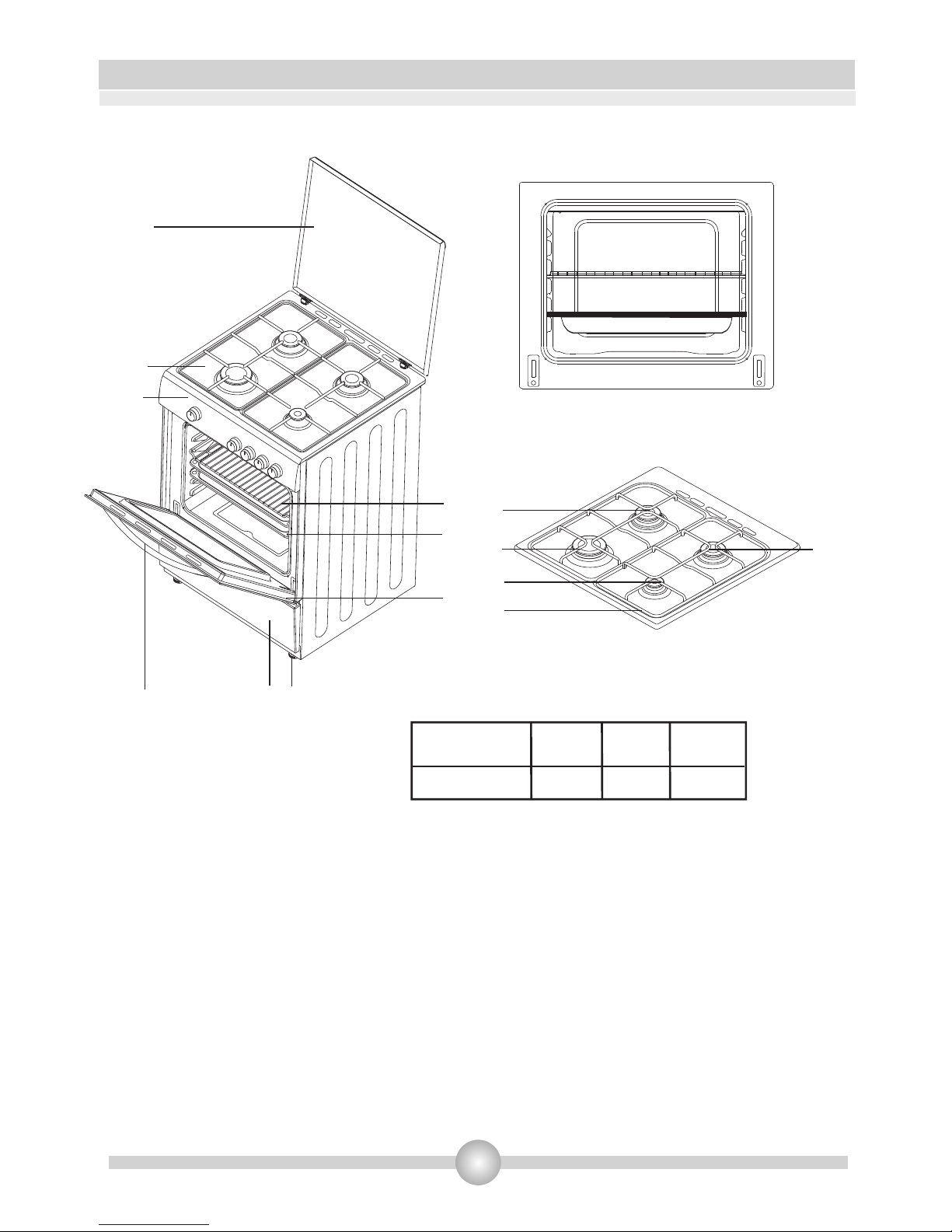
Cooker parts list:
1- Cooktop Cover
2- Cooktop
3- Control Panel
4- Oven Door Handle
5 - Storage compartment door
6- Adjustable feet
7- Oven Door
8- Oven Tray
9-Wire Shelf
MODEL
FSHG 60 60 60 85
DEPTHSIZE(cm)
LENGTH
(cm)
HEIGHT
(cm)
10- Semi-rapid burner
11- Rapid burner
12- Auxiliary burner
13- Pan support grid
14- Semi-rapid burner
10
11
12
13
14
1
2
3
4
5
6
7
8
9
Page 5

4
2. WARNINGS
READ THESE INSTRUCTIONS CAREFULLY AND COMPLETELY BEFORE USING YOUR
APPLIANCE, AND KEEP IT IN A CONVENIENT PLACE FOR REFERENCE WHEN NECESSARY.
THIS MANUAL IS PREPARED FOR MORE THAN ONE MODEL IN COMMON. YOUR APPLIANCE
MAY NOT HAVE SOME OF THE FEATURES THAT ARE EXPLAINED IN THIS MANUAL. PAY
ATTENTION TO THE EXPRESSIONS THAT HAVE FIGURES, WHILE YOU ARE READING THE
OPERATING MANUAL.
General Safety Warnings
- This appliance is intended for domestic household
use only and should not be used for any other purpose
or in any other application, such as for non-domestic
use or in a commercial environment.
- If the supply cord is damaged, it must be replaced
by the manufacturer, its service agent or similarly
qualified persons in order to avoid a hazard.
- This appliance can be used by children aged
from 8 years and above and persons with
reduced physical, sensory or mental capabilities
or lack of experience and knowledge if they
have been given supervision or instruction
concerning use of the appliance in a safe way
and understand the hazards involved. Children
shall not play with the appliance. Cleaning and
user maintenance shall not be made by children
without supervision.
- WARNING: The appliance and its accessible
parts become hot during use. Care should be
taken to avoid touching heating elements.
Children less than 8 years of age shall be kept
away unless continuously supervised.
- WARNING: Unattended cooking on a hob with
Page 6

5
2. WARNINGS
fat or oil can be dangerous and may result in
fire. NEVER try to extinguish a fire with water,
but switch off the appliance and then cover
flame e.g. with a lid or a fire blanket.
- WARNING: Danger of fire: do not store items
on the cooking surfaces.
- Any spillage should be removed from the lid
before opening.
- The hob surface should be allowed to cool
before closing the lid.
- The appliance is not intended to be operated
by means of an external timer or separate
remote-control system.
- During use, the appliance becomes hot. Care
should be taken to avoid touching heating
elements inside the oven.
- Do not use harsh abrasive cleaners or sharp
metal scrapers to clean the oven door glass
since they can scratch the surface, which may
result in shattering of the glass.
- Do not use steam cleaners for cleaning the
appliance.
- CAUTION: Accessible parts may become hot
during use. Young children should be kept
away.
• Your appliance is produced in accordance with all applicable local and international
standards and regulations.
Page 7

6
2. . WARNINGS
• Maintenance and repair work must be made only by authorised service technicians.
Installation and repair work that is carried out by unauthorised technicians may endanger
you. It is dangerous to alter or modify the specifications of the appliance in any way.
• Prior to installation, ensure that the local distribution conditions (nature of the gas and
gas pressure) and the requirements of the appliance are compatible. The requirements for
this appliance are stated on the label.
• Do not try to lift or move the appliance by pulling the door handle.
• This appliance is not connected to a combustion products evacuation device. It shall be
installed and connected in accordance with current installation regulations. Particular
attention shall be given to the relevant requirements regarding ventilation.
• If after 15 s the burner has not lit, stop operating the device and open the kitchen door
or window and/or wait at least 1 min before attempting a further ignition of the burner.
• These instructions are only valid if the country symbol appears on the appliance. If the
symbol does not appear on the appliance, it is necessary to refer to the technical
instructions which will provide the necessary instructions concerning modification of the
appliance to the conditions of use of the country.
• All possible security measures have been taken to ensure your safety. Since the glass
may break, you should be careful while cleaning to avoid scratching. Avoid hitting or
knocking on the glass with accessories.
• While the oven door is open, do not let children climb on the door or sit on it.
Installation Warnings
• Do not operate the appliance before it is fully installed.
• The appliance must be installed by an authorised technician and put into use. The
producer is not responsible for any damage that might be caused by defective placement
and installation by unauthorised people.
• When you unpack the appliance, make sure that has not been damaged during
transportation. In case of any defect; do not use the appliance and contact a qualified
service agent immediately. As the materials used for packaging (nylon, staplers,
styrofoam...etc) may cause harmful effects to children, they should be collected and
removed immediately.
• Protect your appliance against atmospheric effects. Do not expose it to effects such as sun,
rain, snow etc.
• The surrounding materials of the appliance (cabinet) must be able to withstand a
temperature of min 100°C.
During usage
• When you first run your oven a certain smell will emanate from the insulation materials.
For this reason, before using your oven, run it empty at maximum temperature for 45
minutes. At the same time you need to properly ventilate the environment in which the
product is installed.
• During usage, the outer and inner surfaces of the oven get hot. While opening the oven
door, step back to avoid the hot steam coming out of the oven. There may be a risk of
burns.
• Do not put flammable or combustible materials, in or near the appliance when it is
operating.
• Always use oven gloves to remove and replace food in the oven.
Page 8

• Do not leave the cooker while cooking with solid or liquid oils. They may catch fire on
condition of extreme heating. Never pour water on to flames that are caused by oil. Cover
the saucepan or frypan with its cover in order to choke the flame that has occured in this case
and turn the cooker off.
• Always position pans over the centre of the cooking zone, and turn the handles to a safe
position so they cannot be knocked or grabbed.
• If you will not use the appliance for a long time, plug it off. Keep the main control switch off. Also when
you do not use the appliance, keep the gas valve off.
• Make sure the appliance control knobs are always in the "0" (stop) position when it is not used.
• The trays incline when pulled out. Be careful not to let hot liquid spill over.
• CAUTION: The use of a gas cooking appliance results in the production of heat, moisture and products
of combustion in the room in which it is installed. Ensure that the kitchen is well ventilated especially
when the appliance is in use, keep natural ventilation holes open or install a mechanical ventilation
device (mechanical extractor hood).
• Prolonged intensive use of the appliance may call for additional ventilation, for example opening of
a window, or more effective ventilation, for example increasing the level of mechanical ventilation
where present.
• CAUTION:
Turn off all the burners before shutting the lid.
The hob surface should be allowed to cool before closing the lid.
• When the door or drawer of the oven is open, do not leave anything on it. You may unbalance your
appliance or break the cover.
• Do not put heavy things or flammable or ignitable goods (nylon, plastic bag, paper, cloth...etc) into
the drawer. This includes cookware with plastic accessories (e.g. handles).
During cleaning and maintenance
• Always turn the appliance off before operations such as cleaning or maintenance. You can do it
after plugging the appliance off or turning the main switches off.
• Do not remove the control knobs to clean the control panel.
TO MAINTAIN THE EFFICIENCY AND SAFETY OF YOUR APPLIANCE, WE RECOMMEND YOU
ALWAYS USE ORIGINAL SPARE PARTS AND TO CALL ONLY OUR AUTHORISED
SERVICE AGENTS IN CASE OF NEED.
7
2. . WARNINGS
Page 9
8
3. INSTALLATION
This modern, functional and practical cooker that was manufactured with the parts and materials
of highest quality will meet your cooking needs in every aspect. Before using your cooker, please
read this leaflet carefully to find out all its functions and achieve the best possible results. For
proper installation, consider the following recommendations to avoid any problem or
dangerous situation. They must also be read by the technician who will install the cooker.
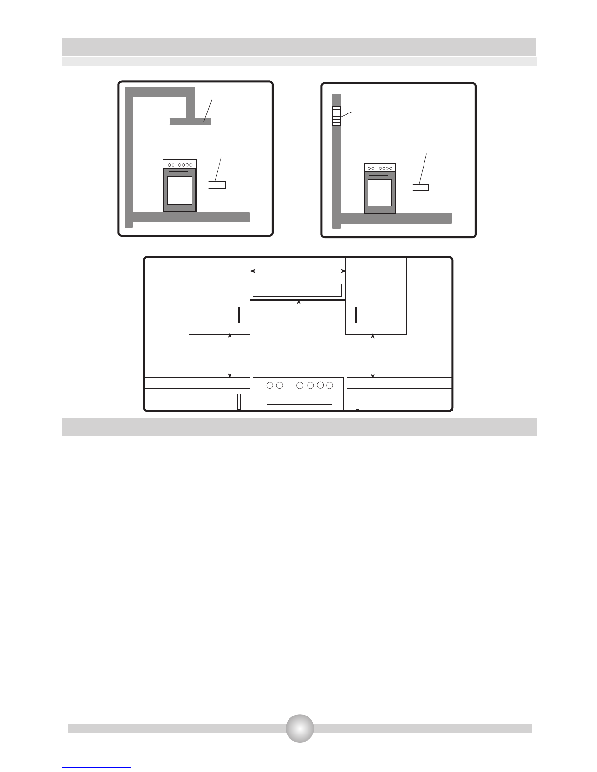
3.1 Installation environment for your cooker
Your cooker must be set up and used in a place where it will always have ventilation. Gas
combustion is made possible by the oxygen in the air. It is therefore necessary that the air be
renewed and that combustion products be discharged in accordance with the regulations. There
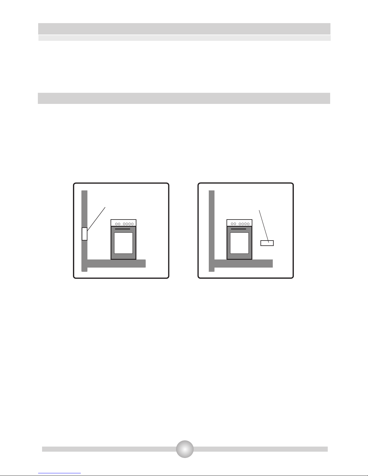
must be a natural ventilation enough to provide the gas to be used in the environment. The
airflow must enter via vents installed on walls in direct contact with the outside (see diagram
below).
While operating, this cooker needs 2m3 /h air per kw input.
•
•
• The airflow must enter through the bottom (minimum 100cm ²) and come out on top (minimum
100cm ²). These vents must therefore have a minimum area of 100 cm2 for the effective passage
of air. These vents should be open and never closed. They should preferably be located near the
rear of the cooker (for the air inlet Fig. 1 and 2) and opposite the burnt gases caused by cooking
(for evacuation) that is to say at least 1.80m above the ground. If you cannot open these vents
toto the outside, where the cooker is installed, the necessary air may also come from another
location provided it is properly ventilated and is neither a bedroom nor a dangerous place.
Evacuating burnt gases
It is advisable to install either an exhaust hood directly connected to a pipe leading directly to the
outside (Fig. 3), or an electrical ventilator installed on the window or outside wall (Fig. 4) to
evacuate flue gases directly outside. The electrical ventilator power supply must be calculated in
order to renew the air in the kitchen 4-5 times per hour.
Air inlet section
2
min. 100cm
Air inlet section
2
min. 100cm
Figure 1
Figure 2
Page 10
9
3. INSTALLATION
Extracting
hood
Electrical ventilator
Air inlet section
2
min. 100cm
Air inlet section
2
min. 100cm
Figure 3
Figure 4
•
•
•
•
•
•
3.2 Installing your cooker
The cooker may be placed near another piece of furniture, but make sure that the height of
surrounding furniture does not exceed the cooker height (see fig. 5).
If kitchen furniture are above the cooker, leave a space of at least 10cm between the sides of the
cooker and the furniture.
The minimum height between the cooktop and the hood (or wall units) is shown in Fig. 5. The
exhaust hood must be located at least 65cm from the cooktop. If there is no hood, the height of
.
the furniture located above the cooktop must not be less than 70cm
Leave a 2cm space between the rear of the cooker and the wall, and between the sides and
adjacent furniture.
Pay attention not to place the cooker near a refrigerator; there must be no flammable or
ignitable materials such as curtain, cloth, etc... that may easily get burnt.
Adjacent furniture must be manufactured resistant to temperatures up to 90°C.
Figure 5
Min. 60cm
COOKER HOOD
Min. 42cm
Min. 42cm
Min. 65cm (with hood)
Min. 70cm (without hood )
Page 11
3. INSTALLATION
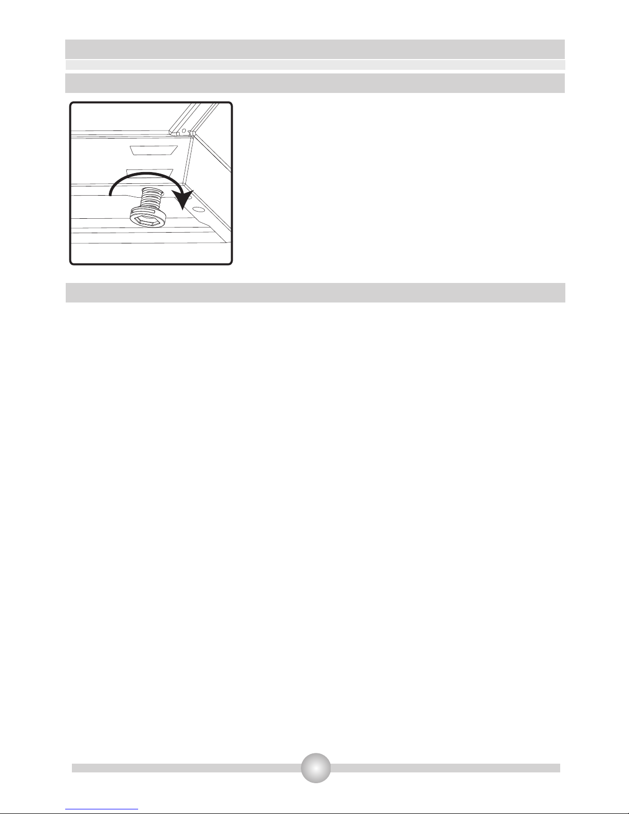
Figure 6
9
3.3 Adjustment of feet
.
3.4 Gas connection
Your stands on 4 adjustable feet. When the is
placed where to be used, check if the product is balanced. If it
is not balanced, you can make the adjustment by turning the
feet clockwise if required. It is possible to raise the appliance
maximum 30mm by the feet. If the feet are adjusted
appropriately, it is required not to move the appliance by
dragging, it should be moved by lifting it up
Assembly of gas supply and leakage check
The connection of the appliance should be performed in accordance with local and international
standards and regulations applicable. You can find the information related to appropriate gas types
and appropriate gas injectors on technical data table. If the pressure of used gas is different than
these values stated or not stable in your area, it may be required to assemble an available pressure
regulator on the gas inlet. It is certainly required to contact to the authorized service to make these
adjusments.
The points that must be checked during flexible hose assembly
If the gas connection is made by a flexible hose that is fixed on the gas inlet of appliance, it must be
fixed by a pipe collar as well. Connect your appliance with a short and durable hose that is as close
as possible to the gas source. The hose's permitted maximum lenght is 1.5m. The hose that brings
gas to the appliance must be changed once a year for your safety.
0
The hose must be kept clear from areas that may heat up to temperatures in excess of 90 C. The
hose must not be ruptured, bent or folded. It must be kept clear of sharp corners, moving things,
and should not be defective. Before assembly, it must be checked whether there is any production
defect.
As gas is turned on, all connection parts and hose must be checked with soapy water or leakage
fluids. Do not use naked flame to check gas leakage. All metal components used during gas
connection must be clear of rust. Also check the expiry dates of components to be used.
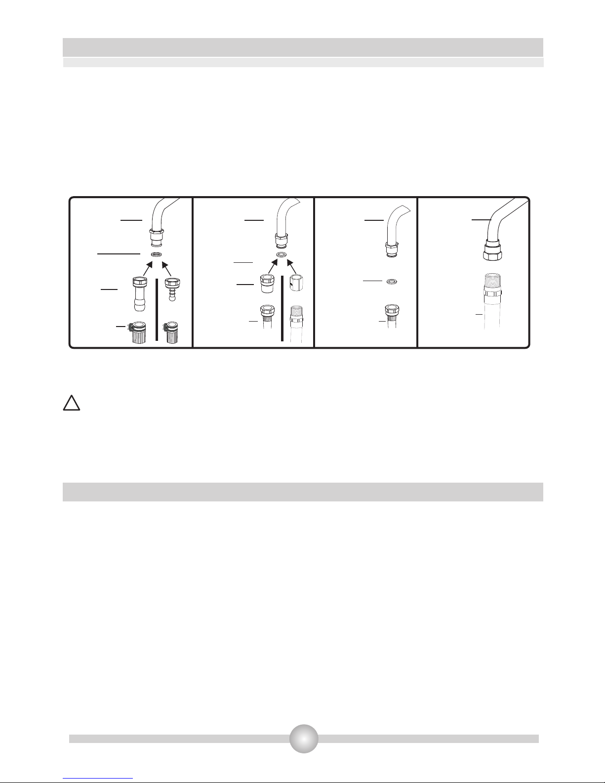
The points that must be checked during fixed gas connection assembly
To assemble a fixed gas connection (gas connection made by threads, e.g. a nut), there are different
methods used in different countries. The most common parts are already supplied with your appliance.
Any other part can be supplied as spare part.
During connections always keep the nut on the gas manifold fixed, while rotating the counter-part. Use
spanners of appropriate size for safe connection. For all surfaces between different components,
product product
Page 12
3. INSTALLATION
10
always use the seals provided in the gas conversion kit. The seals used during connection should
also be approved to be used in gas connections. Do not use plumbing seals for gas connections.
Remember that this appliance is ready to be connected to gas supply in the country for which it has
been produced. The main country of destination is marked on the rear cover of the appliance. If you
need to use it in another country, any of the connections in the figure below can be required. In
such a case, learn the appropriate connection parts and obtain those parts to perform a safe
connection.
It is required to call the authorized service to be able to make the gas connections appropriately
and in compliance with safety standards.
Surely do not use any match or lighter for control of gas leakage
The gas inlet of this product is on the right side of the appliance. If connection point needs to be
moved to the left side of the appliance, you can request an extension pipe from your authorized
service.
During the electric connection, follow the instructions stated in the user manual
The earthing cable must be connected to the earth terminal
You have to ensure the power cord with suitable insulation to be connected to the power source
during the connection If there is no appropriate earthed electric outlet in accordance with
regulations in the place where the appliance to be installed, contact to our authorized service.
The earthed electric outlet must be close to the appliance.
Do not use an extension cord
The power cord must not touch to the hot surface of the product.
In case the cord is damaged, contact Authorized Service to have it changed
Any wrong electric connection may damage your appliance, as well as endangering your safety,
rendering your guarantee invalid
ATTENTION! .
3.5 Electric connection and safety
.
• .
•
.
• .
•
• .
•
.
Adapter
Gas Pipe Gas Pipe Gas Pipe Gas Pipe
Seal
Seal
Seal
Hose
Fitting
Gas Hose
with Collar
Mechanical
Gas Hose
Mechanical
Gas Hose
Mechanical
Gas Hose
Page 13
12
•
•
•
•
3.6 Changing gas
Warning : The following procedures must be undertaken by authorised service personnel.
Your cooker has been designed to use either liquefied petroleum gas (propane or butane), or
natural gas. The gas burners can be adapted to these different types of gas, by replacing the
corresponding injectors and adjusting the minimum flame length of each burner. The steps
below must be strictly carried out:
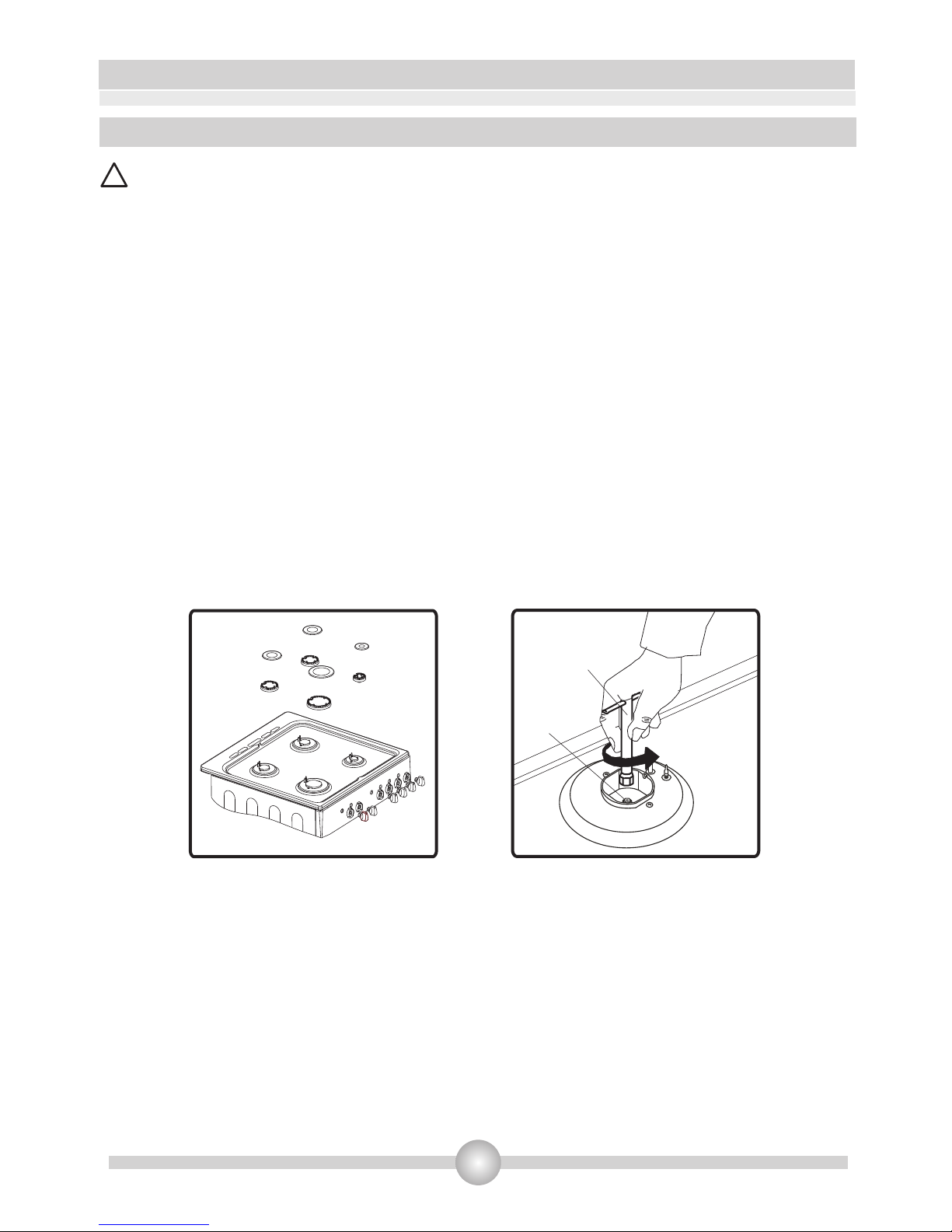
Changing Injectors:
Cooktop burners:
Shut off main gas.
Remove the burner cap and the upper burner (Figure 8).
Unscrew the injectors. For this, use a 7mm spanner (Figure 9).
Install the new injectors in accordance with the type of gas used, as shown on the technical data
table. Be careful to tighten straight the new injectors, because if you mount them sideways, you will
damage the thread of the rack and the rack will need to be changed (and it will not be in guarantee
extent).
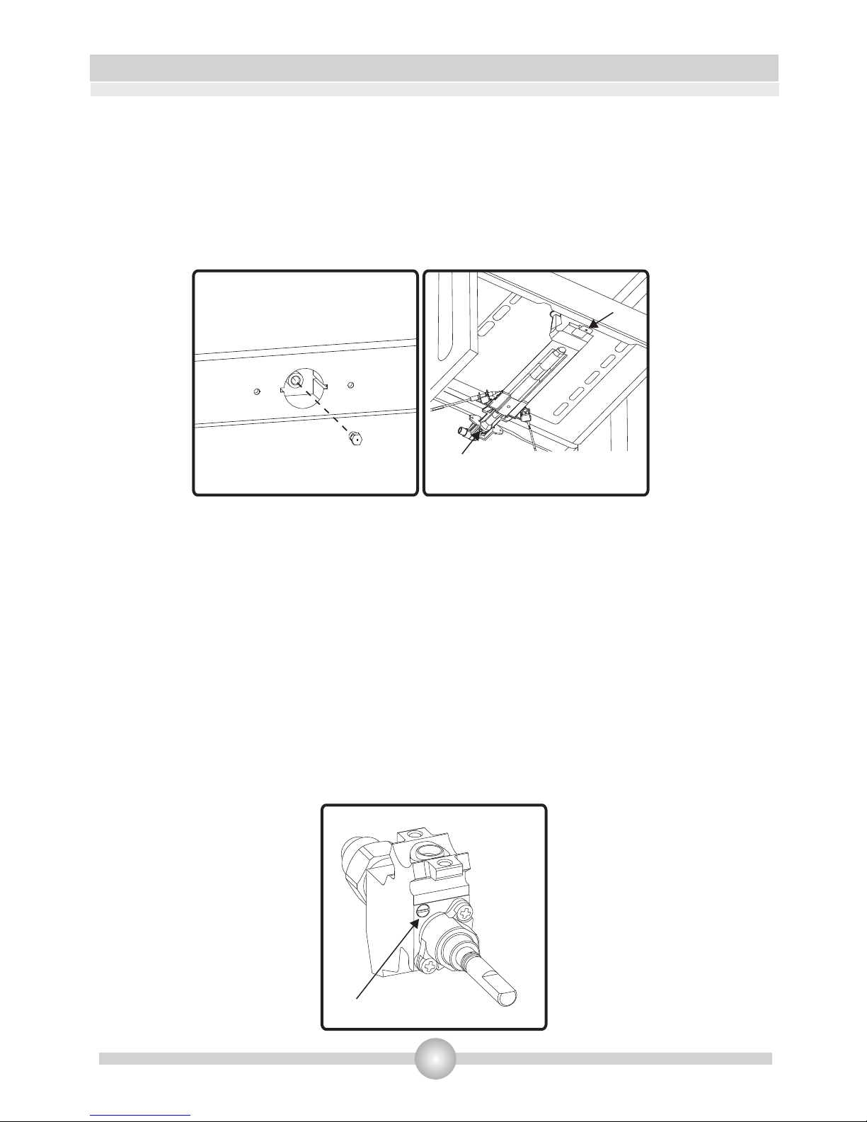
Oven Injectors :
The oven burners are fitted by a single screw that is placed on the tip of the burner.
For the oven burner (below), open the oven door, remove the screws holding the lower sheet.
Open the compartment beneath the oven (pull-down door) to access the front screw located on
the burner (Figure 11). If the cooker has a sub-oven front , you must first dismantle the oven
door to gain access to the screws holding the sheet.
3. INSTALLATION
!
Figure 9
Injector
Spanner
Figure 8
Page 14
3. INSTALLATION
13
Remove the burner screw, and move the burner diagonally to access the injector at the rear
bottom of the muffle oven (Figure 11).
Unscrew the injectors. For this, use a 7mm spanner. Install the new injectors in accordance with
the type of gas used, as shown on the technical data table. Be careful to tighten straight the new
injectors, because if you mount them sideways, you will damage the thread of the rack and the
rack will need to be changed (and it will not be in guarantee extent).
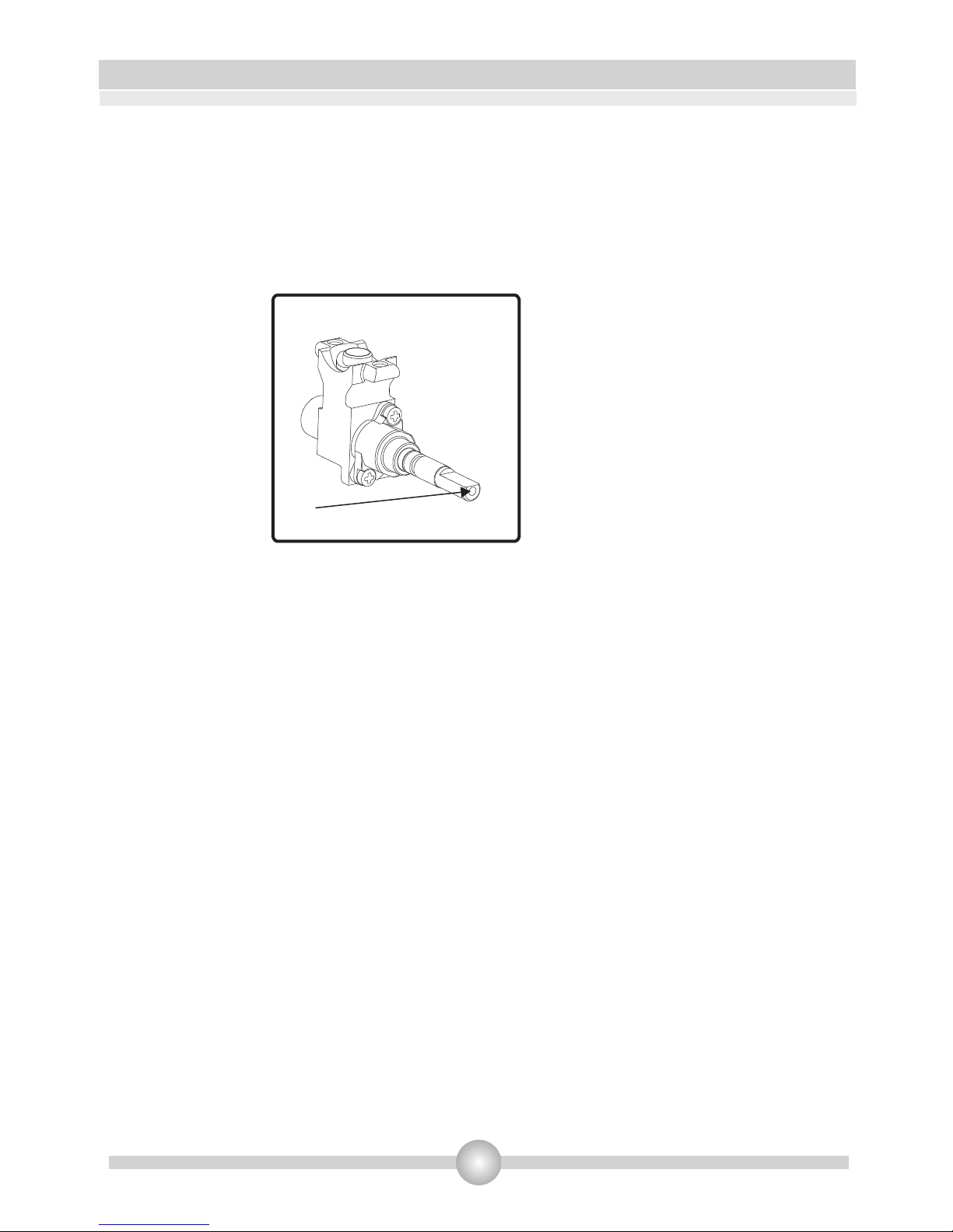
Adjusting the flame to minimum on the valve
The flame length at minimum position is adjusted with a flat screw located on the valve. For valves
with thermocouple, the screw is located on the side of the valve spindle (Figure 12).
To determine the min. position, ignite the burners one after another and set them at minimum
position. With the help of a small screwdriver fasten or loosen the by pass screw around 90
degrees. When the flame has a length of at least 4mm, the adjustment is correct. For control, make
sure that the flame does not die out when passing from the maximum position to the minimum
position. Create an artificial wind with your hand toward the flame to see if the flames are stable.
Figure 10 Figure 11
Screw
Injector
Figure 12
Bypass screw
Valve with thermocouple
Page 15
3. INSTALLATION
14
For the oven burner, let it run at minimum position for 5 minutes. Open and close the oven
door 2-3 times to check the stability of the burner flame.
During the conversion from LPG to NG, the bypass screw must be unscrewed. When converting
from NG to LPG, the same screw must be tightened up. During this adjustment, make sure the
cooker is unplugged and the gas supply is open.
Changing the Gas Inlet:
Regularly check the expiry date of your cooker gas pipe. When the expiry date is reached, it is
necessary to change the hose.
These pipes are available on the market and must be consistent with current standards.
After changing the hose, you should check that there is no leakage by referring to the
information in the above paragraph: Connecting gas and checking leakage.
Figure 17
Figure 15
B
Screw(inside the hole)
Valve without flame failure device
Page 16

4. USE OF YOUR PRODUCT
15
•
4.1 Using gas burners
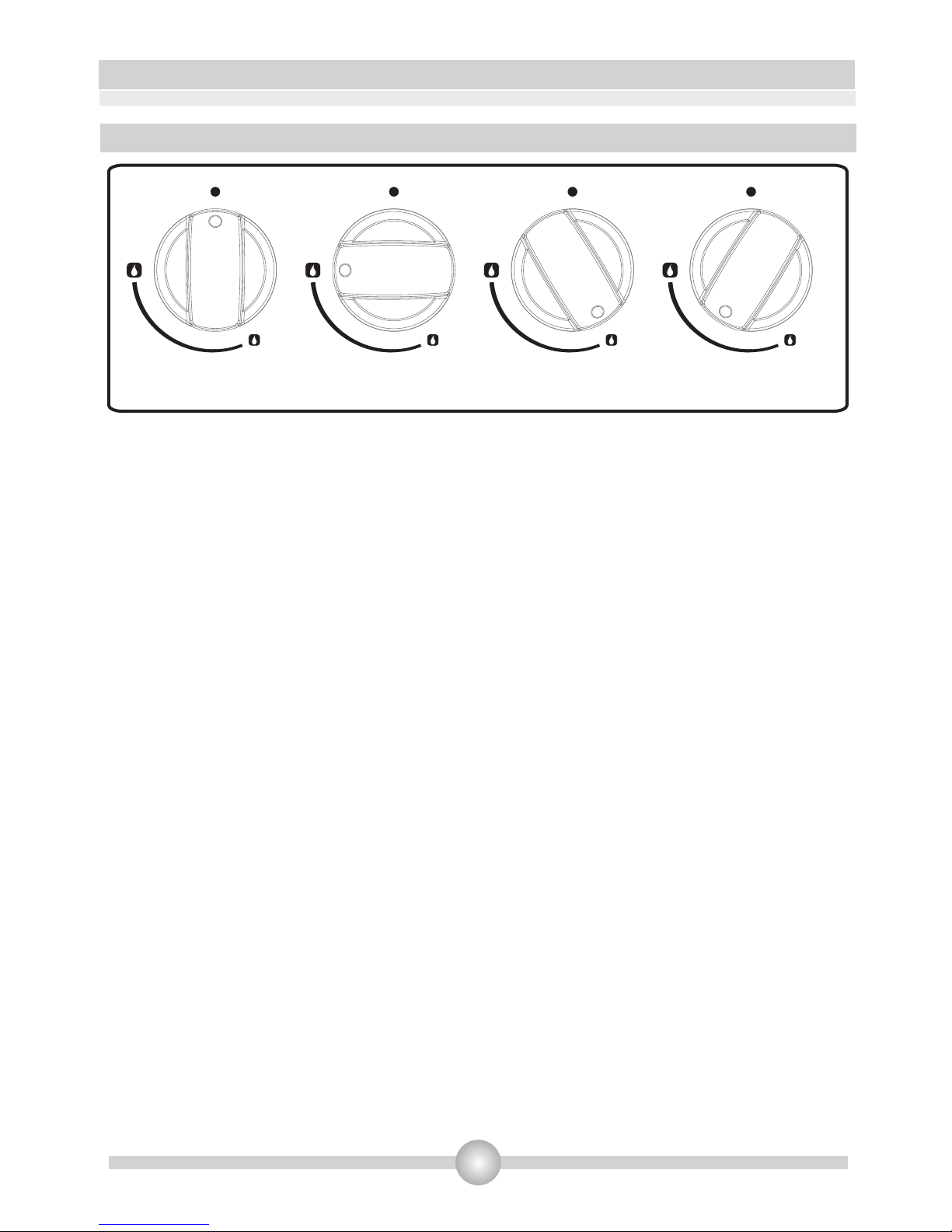
Igniting the burners
The symbols of the levers on the control panel indicate the position of the burner.
Manual Ignition of the Gas Burners
If your cooker is not fitted with electrical ignition or in case there is a failure in the grid, follow
the procedures listed below:
For cooktop burners: To turn one of the burners, press and turn the valve lever concerned
counterclockwise until maximum position and immediately ignite a match or gas lighter near
the crown burner holes. Move the ignition source away as soon as you see a stable flame.
For cooktop burners with thermocouple: Cooktops fitted with safety thermocouple provide
security when the flame goes out accidentally. For this reason, during the manual ignition, press
and hold the valve lever until you see stable flames. If the flames remain unstable after releasing
the button, repeat the procedure. If the flame goes out, the thermocouple system will close off
the said gas valve towards the burner and will prevent any accumulation of unburned gas. You
must wait at least 90 seconds before re-igniting a gas burner after an automatic cut.
For the oven burner (fitted with thermocouple): All oven burners are fitted with safety
thermocouple and provide security when the flame goes out accidentally. To ignite the oven
burner, press and turn the oven valve lever counterclockwise until it reaches maximum position.
While pressing the lever, immediately ignite a match or gas lighter near the ignition hole located
on the left front of the burner. Once the burner is lit with a steady flame, withdraw the ignition
source at once and hold pressed for about 3 seconds. If the flames remain cut out after
releasing the knob, repeat the procedure. If the flame goes out, the thermocouple system will
shut off the gas inlet of the oven valve towards the burner and will prevent any accumulation of
unburned gas. If the oven burner does not ignite after you keep the burner knob pressed for at
least 30 seconds, open the oven door and do not attempt re-ignition until at least 90 seconds.
When oven flames go out accidentally, repeat the same procedure.
Page 17
4. USE OF YOUR PRODUCT
16
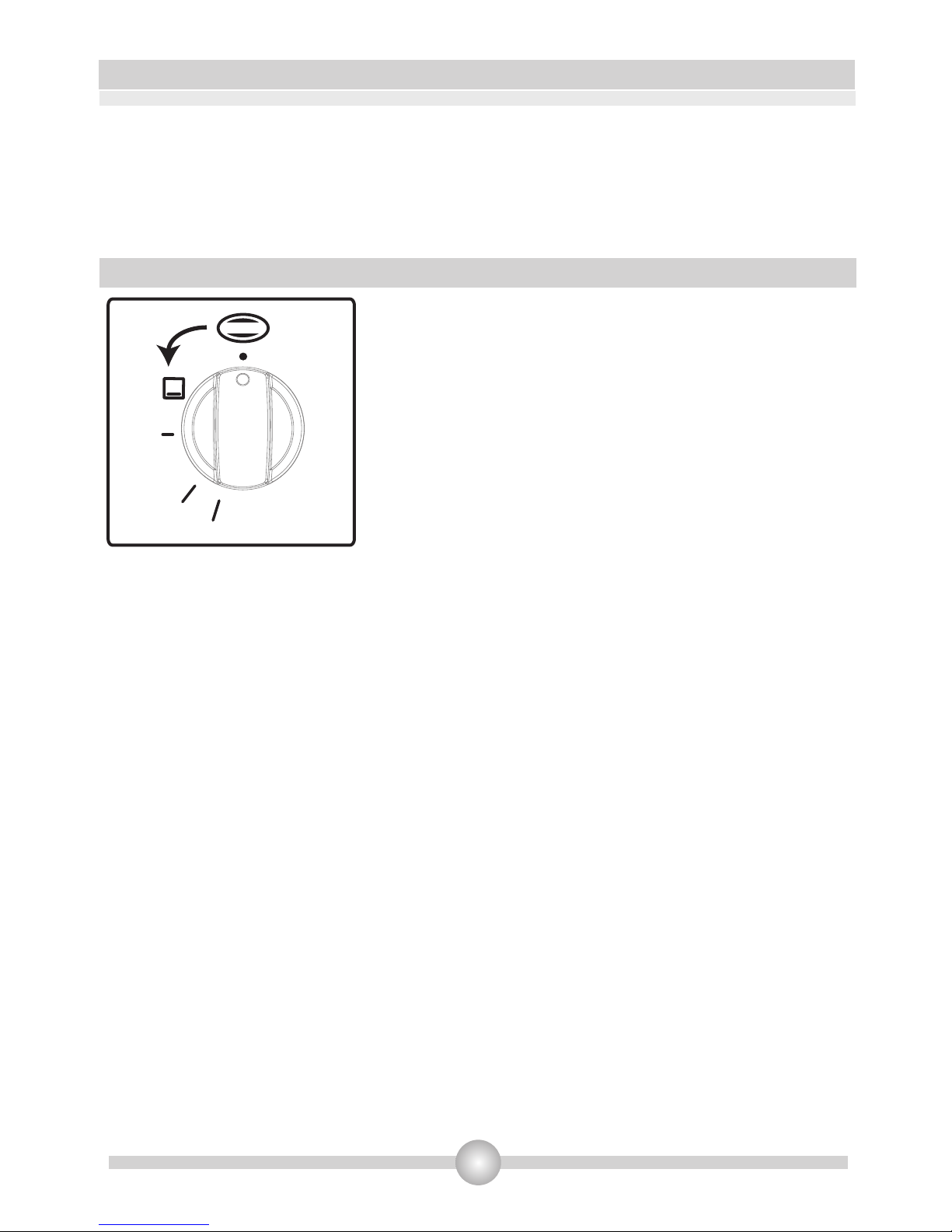
MAX Position
Off Position
Intermediate
MIN Position
Figure 14
4.1.1
Cooktop valve levers have 3 positions: Off (0), max (big flame symbol) and min (small flame
symbol). After igniting the burner to "Max" position (as explained above), you can adjust the flame
length between "Max" and "Min" positions. Do not put the lever between the "Max” and “Off”
positions.
Using cooktop burners
Page 18
4. USE OF YOUR PRODUCT
17
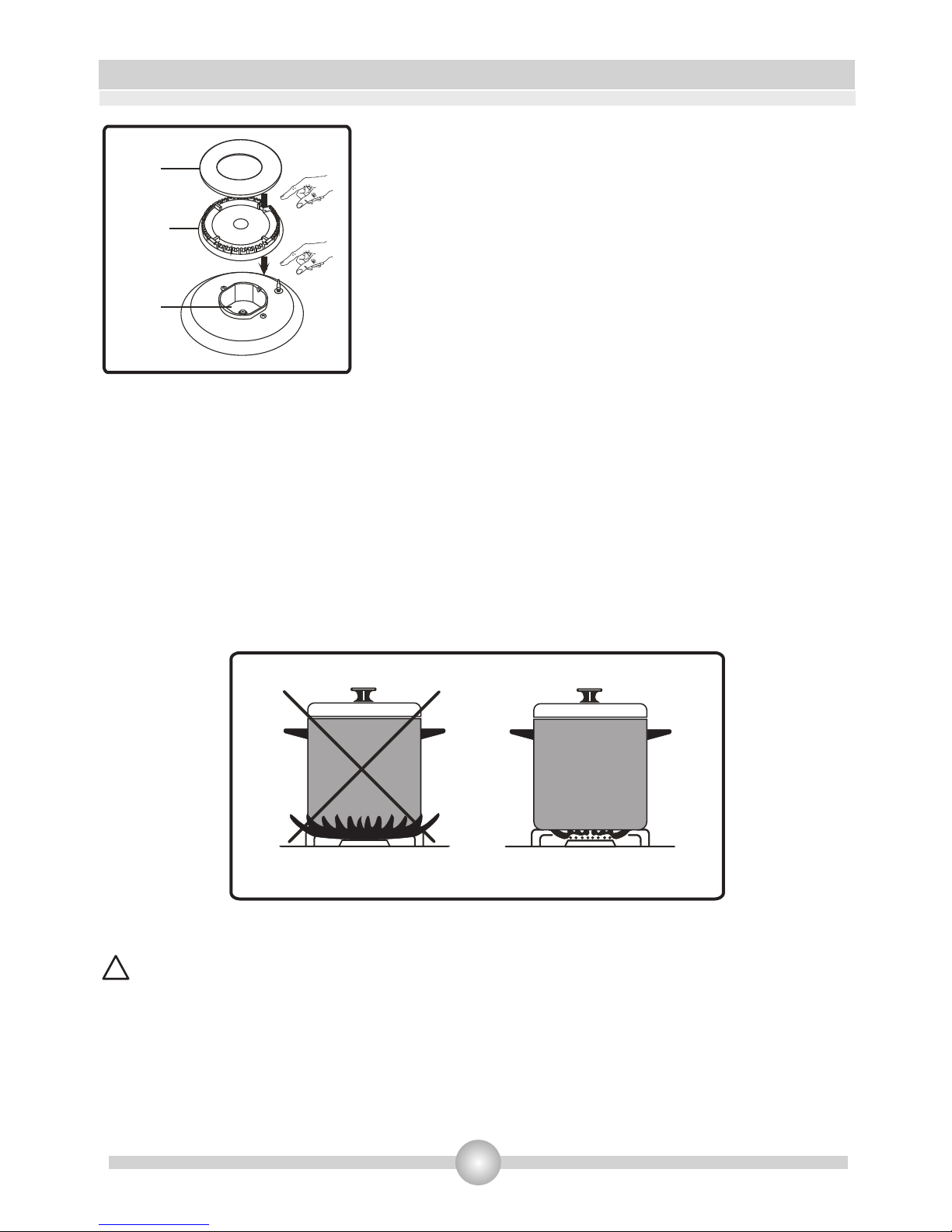
After the ignition, check the flames visually. If you see
yellow tip, lifted or unstable flames; turn the gas flow off,
and check the position of burner caps and crowns (fig.15).
Take note: these are very hot, let them cool to avoid burning
yourself. Be careful that no liquid flows inside the burners. If
the flames accidentally escape from the burner, close the
valves, ventilate the kitchen with fresh air, and wait at least 90
seconds before re-igniting.
To stop the cooking, turn the burner lever clockwise until the
mark on the lever is facing the point "0" (lever mark up).
Your cooktop is fitted with burners of different diameters.
The cheapest
way to use the gas is to reduce the flame to minimum position once you reach boiling point. It is
recommended to always cover your cooking pan.
Rapid Burner: 22-26cm
Semi-rapid burner 14-22cm
Auxiliary burner: 12-18cm
In order to obtain the most efficiency
from the cookers, pay attention to the sizes of saucepans that you put the on the cookers and
make sure that the saucepans have flat bases. Do not use saucepans with concave or convex
bottom to avoid wasting energy. Use proper-sized saucepans corresponding to the flame; if you
use containers smaller than those specified below, you will have wasted energy.
When not using your cooker for a long while, always close the gas inlet valve.
Use only flat pans.
Ensure that the base of the pan is dry before placing it on the burners.
WARNING:
•
•
Figure 16
!
Cap
Crown
Burner
Figure 15
Page 19
•
•
The temperature of parts exposed to the flame can be very high when in use. So, it is imperative
to keep children and animals out of the reach of the burners during and after cooking.
After use, the cooktop remains hot for a long time. Do not touch it and do not place objects on
it.
4.1.2 Using the gas oven burner
Preheating
When you need to preheat the oven, we recommend you do so 10 minutes before placing a dish.
For recipes needing high temperatures, e.g. bread, pastries, scones, souffles, etc..., best results
are achieved if the oven is preheated first. For best results when cooking frozen or chilled food
always preheat the oven first.
Cooking
Your cooker has been delivered with wire shelf and oven tray. You may also use glass dishes,
cake pans, oven plates specially adapted to oven baking, which you may find on the market.
Make sure you follow the instructions given by the manufacturer on the possible use of the
dishes. If small sized containers are used, place them on the shelf such that they are precisely in
the middle of the wire. The following instructions should also be followed for all glazed dishes.
If food for cooking does not cover the entire surface of the cooktop, if it is food from the freezer,
the tray may undergo changes in shape due to high temperatures caused by cooking. The tray
will take back its original shape only when it has completely cooled after cooking. This is a
perfectly normal phenomenon caused by heat transfer.
If you use dishes and other glassware for cooking, do not expose directly to cold after taking
them out of the oven. Do not place on cold or wet surfaces. Place them on a dry kitchen towel or
on a trivet, and make sure they cool slowly, so as to prevent them from breaking.
•
•
•
•
• Be careful not to put the oven tray on the bottom of the oven because it may overheat and
damage the oven enamel.
18
4. USE OF YOUR PRODUCT
Figure 18
After igniting the oven burner as explained above, you may
adjust the temperature inside the oven, by positioning the
control in front of the signs on the control panel.
Do not operate the oven by placing the lever
between the "Off" position and the point indicating min
temperature (counterclockwise). Always use the oven
between the maximum and minimum positions. To stop the
cooking, turn the burner lever clockwise until the mark on the
lever is facing the point "0" (lever mark up).
If your oven
is fitted with an oven thermostat; refer to the temperature
table below to select temperature according to the food
cooked.
290
230
150
• It is important to ensure that the pan is centered correctly above the burners.
Page 20
19
4. USE OF YOUR PRODUCT
•
•
•
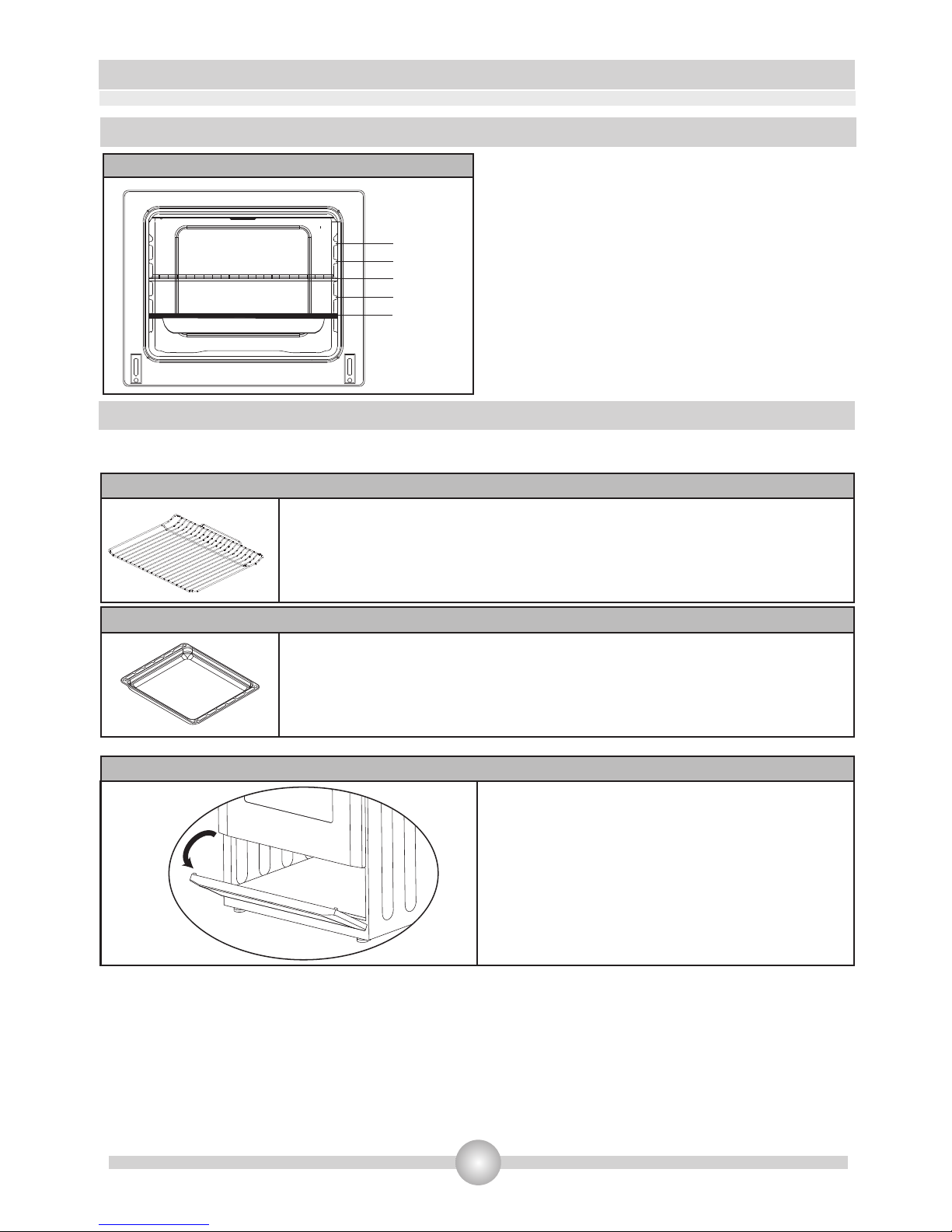
4.2 Accessories used in oven
The oven is supplied with accessories. You may also use accessories you purchase from the
market (but they must be heat and flame resistant). You can also use glass dishes, cake moulds,
special oven trays that are appropriate for use in oven. Pay attention to the manufacturer's user
instructions for accessories.
In case a small-sized dish is used, place the dish at the centre of the grid so that stands
correctly.
Do not place a glass baking pan in a cold environment immediately after cooking. Do not place
it on cold and wet surfaces either. Make sure it cools down gradually on a trivet or cloth,
otherwise it will break.
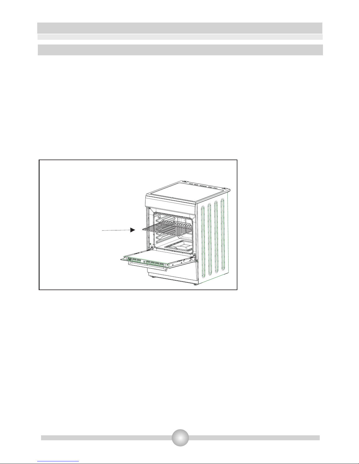
WARNING- Fit
the grid correctly
into any
correspondent
rack in the oven
cavity and push it
to the end.
Page 21
20
4. USE OF YOUR PRODUCT
The medium-sized tray is used for cooking stews.
To position this tray correctly in the cavity, put it to any rack and push
the tray fully home.
This compartment is used to store oven
accessories.
Do not put any flammable material in this
compartment.
Medium-sized tray
Oven accessories
The grid is used in supporting different cooking utensils.
To position grid correctly in the cavity, put it to any rack and push the
grid fully home.
Wire Grid
* Accessories for your oven may be different depending on the model.
Oven muffle
Positions on moulded slides
Position 5
Position 4
Position 3
Position 2
Position 1
Flapping door
Page 22
21
5. CLEANING AND MAINTENANCE
5.1
Make sure all burner control levers and controls are turned off and the cooker is cold before
cleaning the oven.
Check whether they are appropriate and recommended by the manufacturer, before using the
cleaning materials on your oven. Do not use caustic creams, abrasive cleaning powders, , scouring
pads, thick steel wool or hard tools to avoid damaging surfaces. In case liquids overflows around
your oven, the enamelled place may be damaged. Immediately clean up spilled liquids with a
suitable product.
Cleaning inside the oven
The inside of enamelled oven is cleaned in the best way when the oven is warm. After each use,
wipe the oven with a soft cloth that has been dampened with soap water. Later wipe it with a wet
cloth once more and then dry it. It may be required to use a liquid cleaning material from time to
time for thorough cleaning. Do not clean with dry/powder cleaners or steam cleaners.
Cleaning
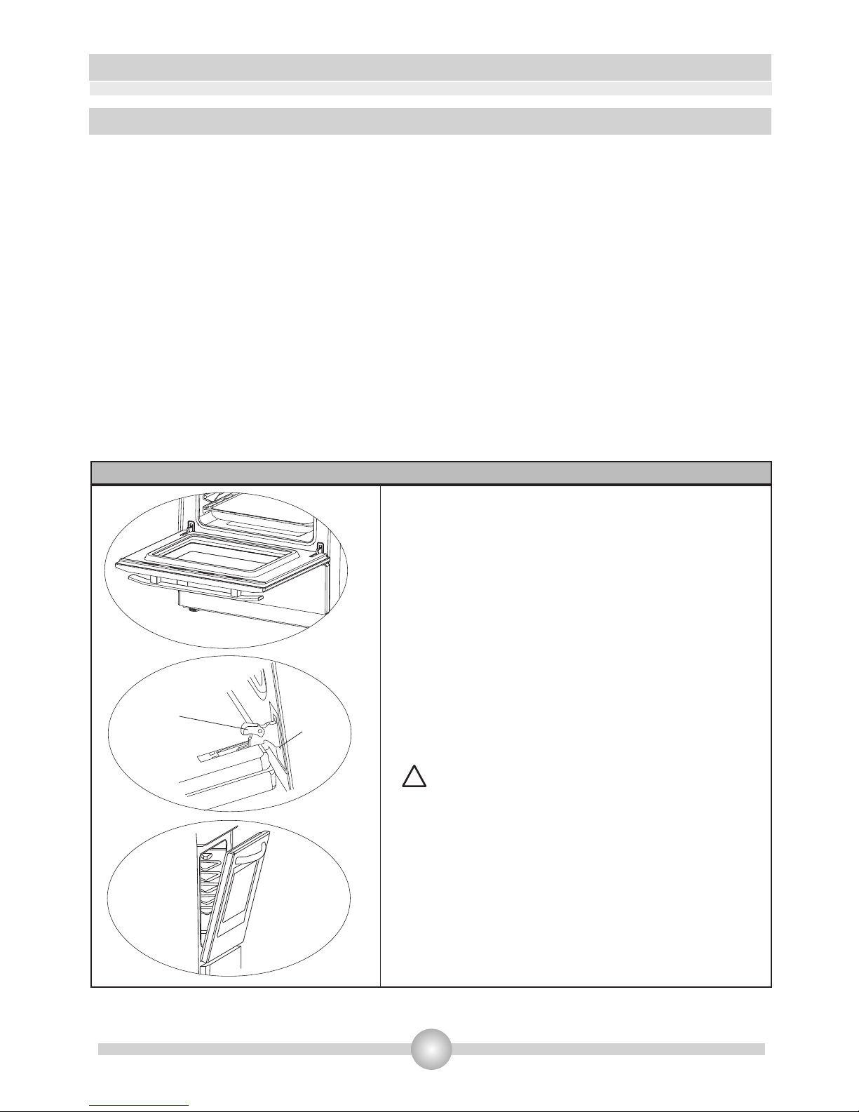
To dismantle the oven door
Tightening
latch
Recessed
support
1
2
3
To dismantle the oven door
Open the oven door (1).
Open the tightening latch up to the final
position (2).
Close the door until it is almost completely
closed as shown in the third diagram and
remove the door by pulling it.
Make sure that the embedded supports are
well positioned on the hinge support as shown in
the second diagram.
Reassembling the door is done by reversing the
procedure explained above. Make sure the
tightening latches are well refitted.
:
•
•
•
!
Page 23

22
5. CLEANING AND MAINTENANCE
Cleaning gas burners
Remove enamelled grilles, burner caps and crowns(Figure 15).
Clean them with soapy water
Rinse and dry with a soft cloth (do not leave them wet)
After cleaning, make sure that you re-assemble the parts correctly.
Do not clean any part of the cooktop with metal sponge. It causes the surface to be scratched.
The upper surfaces of enamel grills may deteriorate over time due to their use and the burner
flames. These parts will not get rusted and it is not a production fault.
When cleaning the cooktop plate, make sure that no water flows inside the burners to avoid
blocking the injectors.
Other Controls
Check the expiry date of the gas supply pipe regularly. If the date expires, please change it quickly.
In case of problems when using the control levers of the burners and oven (eg levers difficult to
turn), please contact the customer service.
•
•
•
•
•
•
•
Enamelled Parts:
In order to keep them as new, it is necessary to clean them frequently with mildly warm soapy
water and then dry with a soft tissue. Do not wash them while hot and never use abrasive
powders or abrasive cleaning materials. The following elements should not have prolonged
contact with the enamelled parts: vinegar, coffee, milk, salt, water, lemon, or tomato juice,
otherwise they will cause irreparable damage to the enamel surface.
Stainless Steel:
Stainless steel parts must be cleaned regularly with mildly warm soapy water and a soft sponge
and then dried with a soft cloth. Do not use abrasive powders or abrasive cleaning metarials. The
following elements should not have prolonged contact with the enamelled parts: vinegar, coffee,
milk, salt, water, lemon, or tomato juice, otherwise they will cause irreparable damage to the
stainless steel surface.
5.2 Maintenance
Page 24

•
•
•
•
•
6.1 Requirements before contacting the customer service
If the cooker does not operate:
Check that the cooker is properly connected to the gas supply and that the propane or butane
bottles are not empty.
If the oven does not heat:
Heat has perhaps not been settled with the control lever of the oven.
Cooking (if the lower and upper parts do not cook equally):
Check the location of grilles and trays, cooking time and thermostat temperature
recommended in this leaflet.
Cooktop burners do not operate correctly:
Check that burner parts have been properly repositioned (especially after cleaning or
installation).
The gas supply pressure may be too low or too high. For cookers which operate with LPG bottles
(Propane or Butane), check that the bottles are not empty.
If the problems of the cooker continue even after performing the above checks, contact the
customer service.
6.2 Information on transport
If you need to transport the cooker, keep the original case of the equipment and carry it along.
Follow the transport instructions on the case. Sellotape the burners so that nothing moves during
transportation (better still, put these items in a separate box). Place a paper between the upper
cover and the cooktop, recover the upper cover, and then sellotape it to the cooker side surfaces.
Open the oven door and put the carton or paper on the inside glass of the oven so that the trays
and the grille do not damage the oven door during transportation. Also sellotape the oven door
and the side walls.
If no original case, take measures to protect the cooker, especially its external surfaces (glass and
painted surfaces), against any moves.
23
6. SERVICE AND TRANSPORT
Page 25
24
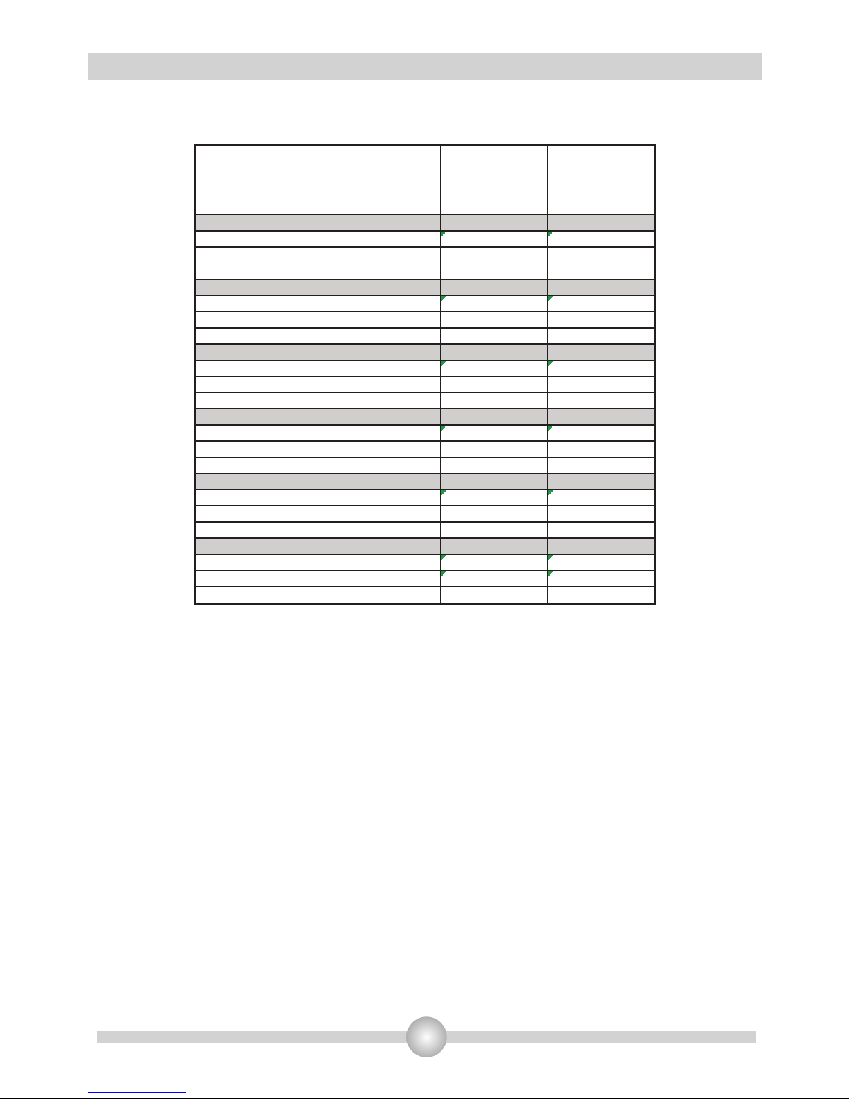
INJECTOR TABLE
G30 28-30mbar 10.3 kW 749 g/h
II2E3B/P DE Clase: 1
NG
G20 20 mbar
LPG
G30 50 mbar
LARGE BURNER
DIA. of INJECTOR (1/100mm) 115 75
NOMINAL RATING (KW) 2,75 3
CONSUMPTION 261,9 l/h 218,1 g/h
MEDIUM BURNER
DIA. of INJECTOR (1/100mm) 97 58
NOMINAL RATING (KW) 1,75 1,75
CONSUMPTION 166,7 l/h 127,2 g/h
MEDIUM BURNER
DIA. of INJECTOR (1/100mm) 97 58
NOMINAL RATING (KW) 1,75 1,75
CONSUMPTION 166,7 l/h 127,2 g/h
SMALL BURNER
DIA. of INJECTOR (1/100mm) 72 43
NOMINAL RATING (KW) 1 1
CONSUMPTION 95,2 l/h 72,7 g/h
OVEN BURNER
DIA. of INJECTOR (1/100mm) 120 68
NOMINAL RATING (KW) 2,8 2,8
CONSUMPTION 266,7 l/h 203,6 g/h
GRILL BURNER
DIA. of INJECTOR (1/100mm) 110 62
NOMINAL RATING (KW) 2,2 2,2
CONSUMPTION 209,5 l/h 160 g/h
Page 26

The symbol on the product or on its packaging indicates that this product
may not be treated as household waste. Instead it shall be handed over to
the applicable collection point for the recycling of electrical and electronic
equipment. By ensuring this product is disposed of correctly, you will help
prevent potential negative consequences for the environment and human
health, which could otherwise be caused by inappropriate waste handling of
this product. For more detailed information about recyling of this product,
please contact your local city office, your household waste disposal service or
the shop where you purchased the product.
Page 27

GASHERD BEDIENUNGS- UND
INSTALLATIONSANLEITUNG
DE
FSHG 60
Page 28

Werte Kunden,
Unser Ziel ist es, Ihnen hochwertige Produkte zu liefern, die Ihre Erwartungen
übertreffen und bieten Ihnen deshalb nur Produkte an, die mit größter Sorgfalt
und unter strengen Qualitätskontrollen in modernen Produktionsanlagen
hergestellt werden.
Diese Broschüre enthält alle erforderlichen Informationen zur Aufstellung und
Verwendung Ihres neuen Herds.
Wir empfehlen Ihnen, diese Bedienungsanleitung sorgfältig durchzulesen,
bevor Sie Ihren Herd in Betrieb nehmen, da sie alle grundlegenden
Informationen zur korrekten Aufstellung, richtigen Verwendung und
regelmäßigen Pflege und Wartung Ihres Herds enthält. Dieser Herd darf nur
von qualifiziertem Personal in Übereinstimmung mit den sicherheitsrelevanten
Normen und Gesetzen installiert werden. Versuchen Sie niemals, den Herd
selbst zu reparieren.
Dieser Herd ist nur für die Verwendung in privaten Haushalten vorgesehen
(gewerbliche Nutzung ist ausgeschlossen). Jegliche andere Verwendung des
Geräts (z. B. Beheizen eines Raums) ist unzulässig und daher gefährlich.
Dieser Herd wurde in Erfüllung der folgenden Richtlinien entwickelt, gebaut
und auf den Markt gebracht:
Sicherheitsanforderungen der "Gas"-Richtlinie 2009/142/EC;
Anforderungen der Richtlinie 93/68/EC.
Page 29

2
INHALT
1. TECHNISCHE EIGENSCHAFTEN
2. SICHERHEITSHINWEISE
Allgemeine Hinweise
Aufstellungshinweise
Während der Verwendung
Reinigung und Wartung
Sicherheit von Kindern
3. EINBAU
3.1 Aufstellungsort/-umgebung des Herds
3.2 Aufstellung des Herds
3.3 Einrichten der Stellfüße
3.4 Gasanschluss
3.5 Umstellung des Gastyps
4. VERWENDUNG
4.1 Verwendung der Gasbrenner
4.1.1 Verwendung der Kochfeld-Brenner
4.1.2 Verwendung der Brenner im Backraum
4.2 Im Herd verwendetes Zubehör
5. REINIGUNG UND WARTUNG
5.1 Reinigung
5.2 Wartung
6. KUNDENDIENST UND TRANSPORT
6.1 Bevor Sie sich an den Kundendienst wenden
6.2 Informationen zum Transport
Page 30

3
1. KURZÜBERSICHT ÜBER DAS GERÄT
Teileliste:
1- Abdeckung Kochfeld
2-Kochfeld
3-Bedienfeld
4-Klappengriff
5-Unterbau oder Auszug vorne
6-Stellfüße
7-Backraumtür
8-Backblech
9-Wire Grid
MODELl
TIEFE
(cm)
LÄNGE
(cm)
HÖHE
(cm)
10-Halb-Schnellkochplatte
11-Schnellkochplatte
12-Zusatzkochplatte
13-Topfhaltegitter
14-Halb-Schnellkochplatte
10
11
12
13
14
1
2
3
4
5
6
7
8
9
FSHG 60 60 60 85
Page 31

4
2. WARNHINWEISE
LESEN SIE DIESE ANLEITUNG VOLLSTÄNDIG UND SORGFÄLTIG DURCH, BEVOR
SIE IHR GERÄT IN BETRIEB NEHMEN, UND HALTEN SIE ES STETS ZUR
VERFÜGUNG WENN NÖTIG.
DIESES HANDBUCH WURDE FÜR VERSCHIEDENE MODELLE EINER REIHE
VERFASST. ES KANN SEIN, DASS IHR GERÄT ÜBER EINIGE EIGENSCHAFTEN, DIE
IN DIESEM HANDBUCH ERLÄUTERT WURDEN NICHT VERFÜGT. ACHTEN SIE AUF
DIE AUSDRÜCKE, DIE EINE ABBILDUNG HABEN, WÄHREND SIE DIESE
BETRIEBSANLEITUNG LESEN.
Allgemeine Sicherheitshinweise
Dieses Gerät kann von Kindern ab 8 Jahren
und älter und Personen mit eingeschränkten
physischen, sensorischen oder geistigen
Fähigkeiten oder mangelnder Erfahrung und
Wissen verwendet werden, wenn sie unter
Aufsicht sind oder ausführliche Anleitung zur
Benutzung des Gerätes in einer sicheren Weise
erhalten haben und die damit verbundenen
Gefahren verstehen. Kinder dürfen nicht mit
dem Gerät spielen. Reinigung und Wartung darf
nicht von Kindern ohne Aufsicht erfolgen.
WARNUNG: Das Gerät und die zugänglichen
Teile werden während des Gebrauchs heiß.
Achten Sie darauf, dass Sie nicht die
Heizelemente berühren. Kinder unter 8 Jahren
sollten ferngehalten werden, es sei denn sie
werden kontinuierlich überwacht.
Page 32

5
2. WARNHINWEISE
WARNUNG: Unbeaufsichtigtes Kochen auf
einem Herd mit Fett oder Öl kann gefährlich sein
und zu Bränden führen. NIEMALS versuchen, ein
Feuer mit Wasser zu löschen, aber schalten Sie
das Gerät aus und dann decken Sie die Flamme
z.B. mit einem Deckel oder einer Löschdecke ab.
WARNUNG: Brandgefahr: lagern Sie keine
Gegenstände auf den Kochflächen.
WARNUNG: Wenn die Oberfläche rissig ist,
schalten Sie das Gerät aus, um die Gefahr eines
elektrischen Schlages zu vermeiden.
Für Kochfelder mit Abdeckung: Entfernen Sie vor
d e m Ö f f n e n d e r A b d e c k u n g a l l e
Verunreinigungen darauf. Lassen Sie die
Kochfelder stets abkühlen, bevor Sie die
Abdeckung schließen.
Das Gerät ist nicht für die Steuerung durch
externe Zeitgeber oder ein separates
Fernbediensystem ausgelegt.
Page 33

6
2. WARNHINWEISE
Zur Vermeidung vom Kippen des Gerätes
müssen die stabilisierenden Halterungen
eingebaut sein.
Während der Verwendung wird das Gerät heiß. Achten
Sie darauf, dass Sie nicht die Heizelemente im Inneren
des Backraums berühren.
Griffe die während der Verwendung für kurze Zeit im
normalen Gebrauch gehalten wurden können heiß
werden
Verwenden Sie keine aggressiven oder scheuernden
Reinigungsmittel oder Metallschaber, um die Scheibe in
der Backraumtür zu reinigen.
Diese können die Oberfläche zerkratzen, was zum
Bersten der Glasscheibe führen kann.
Verwenden Sie keine Dampfreiniger zur Reinigung des
Gerätes.
WARNUNG: Stellen Sie sicher, dass das Gerät
ausgeschaltet ist, bevor Sie die Lampe austauschen,
um die Gefahr von elektrischen Schlägen zu vermeiden.
VORSICHT: Die außen zugänglichen Teile können sehr
heiß werden, wenn das Kochen oder Grillen in
Verwendung ist.
Page 34

7
2. WARNHINWEISE
Halten Sie kleine Kinder fern von dem Gerät.
hr Gerät wurde in Übereinstimmung mit den
einschlägigen lokalen und internationalen Normen und
Vorschriften hergestellt.
Wartungs-und Reparaturarbeiten dürfen nur von autorisierten Service-Technikern vorgenommen werden.
Installations-und Reparaturarbeiten, die durch nicht autorisierte Techniker durchgeführt wurden, können
Sie gefährden. Jegliche Modifikation der technischen Eigenschaften des Gerätes ist gefährlich und daher
verboten.
Stellen Sie vor der Installation sicher, dass die lokalen Netzbedingungen (Gastyp und
Gasdruck oder Strom-Spannung-und Frequenz) und die Anpassung des Gerätes kompatibel
sind. Die Anpassungsbedingungen dieses Gerätes sind auf dem Typenschild angegeben
VORSICHT: Dieses Gerät ist nur ist nur zum Kochen von Speisen und für den Gebrauch im
Haushalt bestimmt und sollte nicht für andere Zwecke oder auf einer anderen Anwendung, z.
B. für gewerbliche und industrielle Anwendung oder in einem kommerziellen Umfeld
verwendet werden.
Heben oder verschieben Sie das Gerät nicht durch Ziehen am Türgriff.
Dieses Gerät ist nicht an ein Abzugsgerät für Verbrennungsprodukte angeschlossen. Es muss in
Übereinstimmung mit den aktuell gültigen Installationsrichtlinien eingebaut und angeschlossen werden.
Besonderes Augenmerk ist dabei auf die relevanten Richtlinien bezüglich der Belüftung zu richten. (Nur für
Gasgeräte)
Wenn der Brenner nach 15 Sekunden noch immer nicht läuft, stoppen Sie ihn, öffnen Sie die Backraumtür
und/oder warten Sie mindestens 1 Minute, bevor Sie nochmals versuchen, ihn zu zünden. (Nur für
Gasgeräte)
Wenn der Brenner nach 15 Sekunden noch immer nicht läuft, stoppen Sie ihn, öffnen Sie die Backraumtür
und/oder warten Sie mindestens 1 Minute, bevor Sie nochmals versuchen, ihn zu zünden. (Nur für
Gasgeräte)
Diese Anleitungen sind nur gültig, wenn das Land-Symbol auf dem Gerät angezeigt wird. Wenn das
Symbol nicht auf dem Gerät angezeigt wird, ist es notwendig, die technischen Anweisungen, die die
erforderlichen Anweisungen zur Änderung des Gerätes an die Bedingungen der Nutzung des Landes
bieten, zu beziehen. (Nur für Gasgeräte)
Es wurden alle erdenklichen Sicherheitsvorkehrungen getroffen, um Ihre Sicherheit zu garantieren. Da
das Glas brechen könnte, sollten Sie bei der Reinigung stets vorsichtig sein, um Kratzer zu vermeiden.
Vermeiden Sie Schläge auf das Glas durch Zubehörgeräte.
Stellen Sie sicher, dass das Netzkabel während der Installation nicht eingeklemmt ist. Wird das Netzkabel
beschädigt, muss es vom Hersteller, dem Vertrieb oder einer ähnlich qualifizierten Person ersetzt werden,
um eine Gefährdung zu vermeiden.
Lassen Sie Kinder niemals auf die Backraumtür klettern oder darauf sitzen, wenn diese offen ist.
Page 35

8
2. WARNHINWEISE
Warnhinweise zur Installation:
Nehmen Sie das Gerät nicht in Betrieb, solange es nicht vollständig eingebaut ist.
Das Gerät muss von einem autorisierten Techniker aufgestellt und in Betrieb genommen werden. Der
Hersteller ist nicht verantwortlich für Schäden, die durch fehlerhafte Aufstellung und Montage durch
nicht autorisierte Personen verursacht werden könnten.
Wenn Sie das Gerät auspacken, stellen Sie sicher, dass es nicht während des Transports beschädigt
wurde. Wenn Sie irgendwelche Beschädigungen entdecken, nehmen Sie das Gerät keinesfalls in
Betrieb und kontaktieren Sie umgehend den autorisierten Wartungsdienst. Da die für die Verpackung
verwendeten Materialien (Nylon, Heftklammern, Styropor etc.) für Kinder gefährlich sein können,
sollten Sie diese einsammeln und sofort entsorgen.
Schützen Sie das Gerät vor Umwelteinflüssen. Setzen Sie es niemals Einflüssen wie Sonne, Regen,
Schnee oder Staub etc. Aus.
Die umgebenden Materialien des Gerätes (Schaltschrank) müssen einer Temperatur von mindestens
100 ° C standhalten.
Während der Verwendung
Wenn Sie Ihren Herd das erste Mal einschalten, kommt es zu einer gewissen Geruchsentwicklung,
die von den Isoliermaterialien und den Heizelementen herrührt. Deshalb sollten Sie den Herd vor der
ersten Verwendung bei maximaler Temperatur für 45 Minuten leer betreiben. Bitte lüften Sie während
dieser Zeit die Umgebung, in welcher das Produkt
Während der Verwendung können die äußeren und inneren Oberflächen des Ofens heiß werden.
Wenn Sie die Backraumtür öffnen, treten Sie etwas zurück, um dem aus dem Backraum
entweichenden heißen Dampf auszuweichen. Es kann die Gefahr von Verbrennungen bestehen.
Legen Sie keine entzündlichen oder brennbaren Materialien, in das Gerät oder in die Nähe des
Gerätes, wenn es in Betrieb ist.
Verwenden Sie stets hitzebeständige Handschuhe, wenn Sie Nahrungsmittel in den Herd geben oder
herausnehmen.
Lassen Sie den Herd beim Kochen mit festen oder flüssigen Fetten nicht unbeaufsichtigt. Diese
könnten bei sehr hohen Temperaturen zu brennen beginnen. Gießen Sie niemals Wasser in
brennendes Fett oder Öl. Decken Sie die Kasserolle oder Pfanne mit dem Deckel zu, um die
Flammen zu ersticken und schalten Sie den Herd ab.
Positionieren Sie Pfannen immer über der Mitte der Kochzone, und drehen Sie die Griffe in eine
sichere Position, damit sie nicht geschlagen oder angefasst werden können.
Wenn das Gerät längere Zeit nicht benutzt wird, ziehen Sie den Netzstecker aus der Steckdose.
Halten Sie den Netzhauptschalter ausgeschaltet. Drehen Sie auch den Gaszufuhrhahn ab, wenn Sie
das Gerät nicht verwenden.
Achten Sie stets darauf, dass die Regler in der Position "0" (Stop), wenn der Herd nicht in Betrieb ist.
Page 36

9
2. WARNHINWEISE
Stellen Sie niemals etwas auf die Backrohrtür oder den Auszug, wenn diese offen sind. Dadurch
könnte das Gerät kippen oder die Klappe beschädigt werden.
Geben Sie keine schweren Gegenstände oder entzündliche, brennbare Objekte (Nylon, Plastikbeutel,
Papier, Stoff etc.) in die untere Ausziehlade. Dazu gehören Kochgeschirr mit Zubehör aus Kunststoff
(z.B. Griffe).
Hängen Sie keine Handtücher, Geschirrtücher oder Kleidung auf das Gerät oder auf seine Griffe.
Reinigung und Wartung:
Schalten Sie das Gerät aus, bevor Sie irgendwelche Reinigungs- oder Wartungsarbeiten
durchführen. Das können Sie machen nachdem Sie das Gerät ausstecken oder den Hauptschalter
ausschalten.
FÜR EINE EINWANDFREIE FUNKTION UND DIE GRÖSSTMÖGLICHE SICHERHEIT SOLLTEN
SIE STETS ORIGINALERSATZTEILE VERWENDEN UND IM BEDARFSFALL NUR EINEN
AUTORISIERTEN WARTUNGSDIENST ANRUFEN.
VORSICHT: Glasabdeckungen können springen, wenn sie zu heiß
werden. Schalten Sie alle Brenner aus, bevor Sie die Abdeckung
schließen. Lassen Sie die Kochfelder stets abkühlen, bevor Sie die
Abdeckung schließen.
Page 37

10
3. INSTALLATION
Dieser moderne, zweckmäßige und praktische Herd wurde aus hochwertigen Teilen und Materialien
gefertigt und wird all Ihren Ansprüchen in jeder Hinsicht gerecht werden. Lesen Sie diese Broschüre
sorgfältig durch, bevor Sie den Herd in Betrieb nehmen, um alle notwendigen Informationen über seine
Funktionen kennenzulernen und die bestmöglichen Resultate zu erzielen. Beachten Sie die folgenden
Empfehlungen, um Probleme oder gefährliche Situationen zu vermeiden und das Gerät richtig
aufzustellen. Sie sind insbesondere für den Techniker, der die Aufstellung des Geräts vornimmt, von
Bedeutung.
3.1 Aufstellungsort/-umgebung des Herds
• Ihr Herd muss an einem Ort aufgestellt und verwendet werden, der gut belüftet ist. Eine
Gasverbrennung ist nur mit dem Sauerstoff in der Luft möglich. Daher muss ein ausreichender
Luftaustausch erfolgen und eine Abführung der Verbrennungsgase in Übereinstimmung mit den
Vorschriften sichergestellt sein. Es muss eine ausreichende Belüftung vorhanden sein, um die
Luftversorgung in der Verwendungsumgebung zu gewährleisten. Die Belüftung muss durch Öffnungen
an Wänden mit direktem Kontakt nach außen (siehe Diagramm unten).
• Im Betrieb benötigt dieses Gerät 2 m3/h Luft je kW Leistung.
• Der Luftstrom muss am Boden eintreten (mindestens 100 cm²) und oben austreten (mindestens
100 cm²). Diese Belüftungsöffnungen müssen also jeweils einen Mindestquerschnitt von 100 cm2 für
einen effektiven Luftdurchsatz aufweisen. Diese müssen stets offen bleiben und dürfen nicht
geschlossen werden. Sie sollten sich nach Möglichkeit in der Nähe der Herdrückseite befinden (für den
Lufteinlass Fig. 1 und 2) bzw. an der Entstehungsstelle der Verbrennungsgase (für den Abzug), alsoe
etwa 1,80 m über Bodenniveau. Können diese Öffnungen nicht dort, wo der Herd aufgestellt ist, von
außen hergestellt werden, kann die erforderliche Verbrennungsluft auch von anderer Stelle zugeführt
werden, sofern diese über ausreichende Belüftung verfügt und es sich nicht um ein Schlafzimmer oder
einen Raum mit besonderen Gefahren handelt.
Abzug der Verbrennungsgase
Es wird empfohlen, entweder eine Abzugshaube mit direkter Rohrverbindung nach außen (Fig. 3)
zu installieren, oder einen elektrischen Ventilator am Fenster oder an der Außenwand (Fig. 4), um
Rauchgase direkt nach außen zu leiten. Die Leistung des Ventilators muss so ausgelegt werden, dass
die Luft in der Küche 4-5 Mal pro Stunde erneuert wird.
Querschnitt des Lufteinlasses
mindestens 100 cm2.
Querschnitt des Lufteinlasses
mindestens 100 cm2.
Abb.1
Abb.2
Page 38

11
3. INSTALLATION
Abzugshaube
Elektrischer Ventilator
Lufteinlass mit
mindestens 100
cm2 Querschnitt
Lufteinlass mit
mindestens 100
cm2 Querschnitt
Abb.3
Abb.4
3.2 Aufstellung des Herds
• Der Herd darf neben weiteren Möbelstücken aufgestellt werden, solange diese nicht höher als der
Herd sind (siehe Abb. 5).
• Befinden sich über dem Herd weitere Möbelstücke, muss ein Abstand von mind. 10 cm zwischen
den Seiten des Herds und dem Möbelstück eingehalten werden.
• Die Mindesthöhe zwischen Kochfeld und Abzugshaube (oder Wandschrank) ist in Abb. 5 gezeigt.
Die Abzugshaube muss mindestens 65 cm Abstand zum Kochfeld haben. Ist keine Abzugshaube
vorhanden, darf der Abstand zwischen Kochfeld und Möbelstück darüber 70 cm nicht unterschreiten.
• Halten Sie einen Abstand von 2 cm zwischen der Rückseite des Herds und der Wand ein, sowie
zwischen den Seiten des Herds und angrenzenden Möbelstücken..
• Achten Sie darauf, den Herd nicht direkt neben einen Kühlschrank zu stellen. Auch dürfen keine
brennbaren oder entzündlichen Materialien wie Vorhänge, Stoffe etc. in der Nähe sein, die leicht
verbrennen.
• Angrenzende Möbelstücke müssen für Temperaturen von mindestens 90 °C ausgelegt sein.
Abb.5
Min. 60cm
DUNSTABZUG
Min. 42cm
Min. 42cm
Min. 65 cm. (mit Haube)
Mind. 70 cm. (mit Haube)
Page 39

Abb.6
3.3 Einrichten der Stellfüße
Der Herd steht auf 4 einstellbaren Standfüßen. Nach dem
Einstellen der gewünschten Position muss die Einrichtung
überprüft werden. Stellen Sie dazu die 4 Stellfüße durch
Anziehen oder Lockern ein (Abb. 6). Der Herd muss absolut
waagrecht aufgestellt werden.
Der max. Einstellspielraum beträgt 30 mm.
Zum Einstellen der Standfüße können Sie den Auszug des
Herds entfernen.
Nach dem Einstellen der Standfüße darf der Herd nicht mehr
durch Ziehen bewegt werden, sonder nur noch durch Heben
(aber nicht an den Türgriffen).
Page 40

2.3 Gasanschluss
Anschluss der Gasversorgung und Leckprüfung
Der Anschluss des Herds muss nach den inländischen und internationalen Standards sowie
einschlägigen Vorschriften vorgenommen werden. Überprüfen Sie zuerst, für welchen Gastyp
der Herd gerüstet ist. Diese Information nden Sie auf einem Aufkleber an der Herdrückseite. Sie
nden die Informationen zu den geeigneten Gastypen und den entsprechenden Gasbrennern
in der Tabelle mit den technischen Daten. Achten Sie darauf, dass der Gaszufuhrdruck für die
Ventile laut den technischen Daten geeignet ist, damit das Gerät möglichst efzient arbeiten kann
und möglichst wenig Gas verbraucht. Wenn der Druck des verwendeten Gases unterschiedlich
zu den genannten Werten oder in Ihrem Gebiet nicht stabil ist, kann es erforderlich werden einen
geeigneten Druckregler auf den Gaseinlass zu montieren. Um diese Einstellungen vornehmen zu
lassen, müssen Sie sich unbedingt an den autorisierten Kundendienst wenden.
Diese Punkte müssen bei der Installation des exiblen Schlauchs geprüft werden
Wenn die Gasverbindung aus einem exiblem Schlauch besteht, der an dem Gaseinlass
des Gerätes befestigt wird, dann muss zusätzlich eine Rohrmanschette angebracht werden.
Verbinden Sie das Gerät mit der Gasquelle mittels eines möglichst kurzen und dichten
Schlauchs. Die maximal erlaubte Schlauchlänge beträgt 1,5 m. Zu Ihrer Sicherheit muss der
Gasanschlussschlauch einmal (1) jährlich ausgewechselt werden.
Der Schlauch muss von Bereichen ferngehalten werden, die sich auf Temperaturen über 900 C
aufheizen können. Der Schlauch darf nicht gerissen sein oder gedehnt oder geknickt werden. Er
muss von scharfen Kanten, sich bewegenden Gegenständen entfernt gehalten werden und darf
nicht beschädigt sein. Vor der Installation muss er auf Produktionsschäden geprüft werden.
Wenn das aufgedreht ist, müssen alle Verbindungsteile und der Schlauch mit Seifenwasser
oder Lecküssigkeiten auf Dichtheit geprüft werden. Es sollten keine Luftblasen zu sehen sein.
Wenn sich solche Blasen zeigen, muss die Anschlussdichtung überprüft werden und dann die
Überprüfung erneut durchgeführt werden. Verwenden Sie zur Dichtheitsprüfung keine offenen
Flammen! Alle für den Gasanschluss verwendeten Metallteile müssen rostfrei sein. Überprüfen
Sie auch die Verfallsdaten der verwendeten Teile.
Diese Punkte müssen bei der Installation des festen Gasanschlusses geprüft werden
Um einen festen Gasanschluss (Gasanschluss mit Gewinde, z. B. einer Mutter) werden in allen
Ländern unterschiedliche Methoden verwendet. Die dafür üblichsten Teile werden schon mit Ihrem
Herd ausgeliefert. Weitere Teile können als Ersatzteile geliefert werden.
Während des Anschlusses müssen Sie die Mutter an der Gassammelleitung immer xieren,
wenn Sie die Kontermutter festdrehen. Verwenden Sie zum sicheren Anschluss Maulschlüssel
mit einer geeigneten Größe. Bei allen Oberächen zwischen den Teilen müssen Sie immer die
Dichtungen verwenden, die mit dem Gasumwandlungskit geliefert wurden. Die verwendeten
Dichtungen müssen auch zu Verwendung bei Gasanschlüssen genehmigt sein. Verwenden Sie
für Gasanschlüsse niemals Sanitärdichtungen!
3. INSTALLATION
Page 41

3. INSTALLATION
Denken Sie daran, dass dieser Herd für den Anschluss an eine Gasversorgung in dem Land
vorgesehen ist, für das er hergestellt wurde. Das Land, für das der Herd hergestellt ist, ist auf
der Rückabdeckung des Gerätes angegeben. Wenn Sie ihn in einem anderen Land verwenden
wollen, können die in der nachfolgenden Abbildung gezeigte Anschlüsse erforderlich werden. In
derartigen Fällen müssen Sie sich mit den örtlichen Behörden in Verbindung setzen, um etwas
über den korrekten Gasanschluss zu erfahren.
Zur Erstellung des geeigneten Gasanschlusses nach den Sicherheitsvorschriften müssen Sie den autorisierten
Kundendienst beauftragen.
ACHTUNG! Verwenden Sie für die Dichtheitskontrolle unter keinen Umständen ein Feuerzeug oder
Streichhölzer!
Ändern der Gaszufuhr:
In manchen Ländern können die Typen für die Gaszufuhr von NG/LPG Gase unterschiedlich sein. In diesem
Fall müssen Sie alle aktuellen Anschlussteile und Muttern (sofern vorhanden) entfernen und die neue Gaszufuhr
entsprechend verbinden. Unter allen Umständen müssen alle Teile, die für einen Gasanschluss verwendet
werden, von den inländischen und /oder ausländischen Behörden genehmigt sein. Für alle Gasanschlüsse
verweisen wir auf die „Anbringung der Gasversorgung und Leckprüfung“ Klausel, die vorstehend erklärt ist.
2.4 Gasversorgung
Vorsicht: Folgende Handlungen dürfen nur von autorisiertem Personal durchgeführt werden.
Ihr Herd ist dazu eingerichtet, mit LPG/Erdgas Gas betrieben zu werden. Die Gasbrenner können an diese
verschiedenen Gastypen angepasst werden, indem die Brennerdüsen entsprechen ausgetauscht und
die minimale Flammhöhe jedes Brenners eingestellt wird. Zu diesem Zweck sind die folgenden Schritte
auszuführen.
Austauschen der Brennerdüsen:
Kochfeldbrenner:
• Trennen Sie die Hauptgasversorgung und nehmen Sie den Herd von der Stromversorgung.
• Entfernen Sie die Abdeckung und den Adapter. (Abb. 7).
• Schrauben Sie die Düsen ab. Verwenden Sie dazu einen 7 mm-Schlüssel (Abb. 8).
• Ersetzen Sie die Düse mit der aus dem Gasumwandlungskit, die den entsprechenden Durchmesser hat,
der für das zu verwendende Gas gemäß der Informationsgrak (die ebenfalls dem Gasumstellungskit beiliegt)
geeignet ist.
Gasschlauch
Gasschlauch
mit Schelle
Mechanischer
Gasschlauch
Mechanischer
Gasschlauch
Mechanischer
Gasschlauch
Gasschlauch Gasschlauch Gasschlauch
Dichtung
Dichtung
Adapter
Dichtung
Schlauchbefestigung
Abbildung 6
Page 42

14
3,6 Umstellung des Gastyps
Warnung: Die folgenden Massnahmen dürfen nur vom autorisierten Kundendienst
durchgeführt werden.
Ihr Herd ist für die Verwendung von Flüssiggas (Propan oder Butan) oder Erdgas vorgesehen. Die
Gasbrenner können an diese verschiedenen Gastypen angepasst werden, indem die Brennerdüsen
entsprechen getauscht und die minimale Flammhöhe jedes Brenners eingestellt wird. Die folgenden
Schritte müssen dazu unbedingt ausgeführt werden:
Austauschen der Brennerdüsen:
Kochfeld-Brenner:
• Schließen Sie die Gaszufuhr und trennen Sie das Gerät vom Netz.
• Entfernen Sie die Brennerkappe und den oberen Brenner (Abb. 8).
• Schrauben Sie die Düsen ab. Verwenden Sie dazu einen 7 mm-Schlüssel (Abb. 9).
Installieren Sie die neuen Düsen je nach verwendetem Gastyp wie in der Tabelle mit den technischen
Daten angegeben. Ziehen Sie die neuen Düsen sorgfältig an; wenn Sie sie seitlich aufsetzen, könnten
Sie das Gewinde am Aufsatz zerstören. In diesem Fall müsste der Aufsatz ausgetauscht werden
Backraum-Düsen:
Der Brenner im Backraum ist mit einer einzelnen Schraube versehen, die sich an der Brennerspitze
befindet.
Für den Backraum-Brenner (unten) öffnen Sie die Backraumtür und entfernen Sie die Schrauben, die
die untere Verkleidung halten. Öffnen Sie das Fach unter dem Backraum (Auszug oder Klappe) um die
vordere Schraube auf dem Brenner zu erreichen (Abb. 12). Wenn der Herd eine Unterbaufront
aufweist, müssen Sie zuerst die Backraumtür ausbauen, um die Halteschrauben der Verkleidung zu
erreichen.
3. INSTALLATION
!
Abb.9
Düse
Schlüssel
Abb.8
Page 43

3. INSTALLATION
15
Entfernen Sie die Brennerschraube und bewegen Sie den Brenner diagonal, um die Düse hinten unten
zu erreichen (Abb. 11).
Schrauben Sie die Düsen ab. Verwenden Sie dazu einen 7 mm-Schlüssel. Installieren Sie die neuen
Düsen je nach verwendetem Gastyp wie in der Tabelle mit den technischen Daten angegeben. Ziehen
Sie die neuen Düsen sorgfältig an; wenn Sie sie seitlich aufsetzen, könnten Sie das Gewinde am
Aufsatz zerstören. In diesem Fall müsste der Aufsatz ausgetauscht werden (dies ist nicht von der
Garantie gedeckt).
Einstellen der Flammhöhe am Ventil auf minimal
Die Flammhöhe wird mit der Flachkopfschraube auf dem Ventil auf minimal gestellt. Bei Ventilen mit
Thermoelement befindet sich die Schraube auf der Seite der Ventilspindel (Abb. 12). Bei Ventilen ohne
Thermoelement befindet sich die Schraube im Ventilschaft. Für eine einfachere Einstellung der
Flammhöhe empfehlen wir, bei Herden mit Thermoelement und Mikroschalter (automatische Zündung)
zuerst das Bedienfeld zu entfernen.
Um die Minimalposition zu bestimmen, zünden Sie die Brenner der Reihe nach an und stellen Sie die
Minimalposition ein. Verändern Sie nun mit einem kleinen Schraubendreher die Bypassschraube um
etwa 90° (festziehen oder lockern). Wenn die Flamme mindestens 4 mm hoch ist, ist die Einstellung
korrekt. Stellen Sie zur Kontrolle sicher, dass die Flamme nicht ausgeht, wenn sie von der Maximal- in
die Minimalstellung geregelt wird. Erzeugen Sie mit der Hand eine Luftströmung zur Flamme, um zu
testen, ob diese stabil ist.
Abb.10 Abb.11
Schraube
Düse
Abb.12
Bypassschraube
Ventil mit Thermoelement
Page 44

3. INSTALLATION
16
Lassen Sie den Backraumbrenner 5 Minuten lang in der Minimalposition brennen. Öffnen und
schließen Sie die Backraumtür 2-3 Mal, um die Stabilität der Brennerflamme zu testen.
Für die Brenner des Grills ist eine Einstellung der Minimalflammhöhe nicht notwendig.
Bei der Umstellung von Flüssig- auf Erdgas muss die Bypassschraube herausgedreht werden. Beim
Umstellen von Erdgas auf Flüssiggas muss diese Schraube festgezogen werden. Bei dieser
Einstellung stellen Sie bitte sicher, dass der Herd vom Netz getrennt und die Gaszufuhr offen ist.
Ändern des Gaszufuhranschlusses:
Überprüfen Sie regelmäßig das Haltbarkeitsdatum des Gasrohrs. Ist das Haltbarkeitsdatum erreicht,
muss der Schlauch ausgetauscht werden.
Diese Rohre sind im Handel erhältlich, achten Sie darauf, dass die aktuell gültigen Normen erfüllt
werden. Nach dem Austauschen des Schlauchs müssen Sie die Dichtheit prüfen. Informationen dazu
finden Sie im obenstehenden Abschnitt: Gas anschließen und Dichtheit überprüfen
Abb.13
Bypassschrauben
Page 45

4. VERWENDUNG IHRES HERDS
17
4.1 Verwendung der Gasbrenner
Anzünden der Gasbrenner
Die Symbole auf den Reglern am Bedienfeld zeigen die Stellung des Brenners an.
• Manuelle Zündung der Gasbrenner
Ist Ihr Herd nicht mit elektrischer Zündung ausgestattet, oder bei einem Ausfall des Stromnetzes,
gehen Sie wie folgt vor:
Für Kochfeld-Brenner: Um den Brenner einzuschalten, drücken Sie den entsprechenden Regler und
drehen ihn gleichzeitig gegen den Uhrzeigersinn in die Maximalstellung. Zünden Sie gleichzeitig mit
einem Streichholz oder einem Gasfeuerzeug das Gas in der Nähe der Brennerdüsenöffnungen.
Sobald Sie eine stabile Flamme sehen, nehmen Sie die Zündquelle weg.
Für Kochfeld-Brenner mit Thermoelement: Kochfelder mit Thermoelement bieten zusätzliche
Sicherheit, wenn die Flamme ausgehen sollte. Halten Sie den Regler daher bei der manuellen
Zündung gedrückt, bis Sie eine stabile Flamme sehen. Wenn die Flamme nach dem Loslassen des
Reglers instabil wird, wiederholen Sie den Vorgang. Wenn die Flamme ausgeht, schließt das
Thermoelement das Gasventil zum Brenner und verhindert so eine Ansammlung von unverbranntem
Gas. Warten Sie daher 90 Sekunden, bevor Sie einen Gasbrenner nach der automatischen
Abregelung erneut zu zünden versuchen.
Für den Backraum-Brenner (mit Thermoelement): Alle Brenner im Backraum/Grill sind mit
Thermoelementen ausgestattet. Diese bieten zusätzliche Sicherheit, wenn die Flamme ausgehen
sollte. Um den Backraum-Brenner einzuschalten, drücken Sie den entsprechenden Regler und drehen
ihn gleichzeitig gegen den Uhrzeigersinn in die Maximalstellung. Zünden Sie gleichzeitig mit einem
Streichholz oder einem Gasfeuerzeug das Gas in der Nähe der Brennerdüsenöffnung links vorne am
Brenner. Sobald Sie eine stabile Flamme sehen, nehmen Sie die Zündquelle weg, halten den Regler
aber noch für etwa 3 Sekunden gedrückt. Wenn die Flamme nach dem Loslassen des Reglers instabil
wird, wiederholen Sie den Vorgang. Wenn die Flamme ausgeht, schließt das Thermoelement das
Gasventil zum Brenner und verhindert so eine Ansammlung von unverbranntem Gas. Wenn der
Backraumbrenner nicht zündet, nachdem Sie den Regler für mindestens 30 Sekunden gedrückt
gehalten haben, öffnen Sie zunächst die Backraumtür und warten Sie 90 Sekunden, ehe Sie erneut
eine Zündung versuchen. Auch wenn die Flamme im Backraum ausgeht, wiederholen Sie diesen
Vorgang.
Page 46

4. VERWENDUNG IHRES HERDS
18
MAX-Stellung
Aus-Stellung
Zwischenstellung
MIN-Stellung
Abb.14
4.1.1 Verwendung der Kochfeld-Brenner
Die Regler für die Brenner im Kochfeld haben 3 Stellungen: Aus (0), Max (großes Flammensymbol)
und Min (kleines Flammensymbol). Nach dem Zünden der Brenner in der Stellung "MAX" (wie oben
beschrieben), können Sie die Flammhöhe auf eine Stellung zwischen "MAX" und "MIN" regeln. Drehen
Sie den Regler nicht in die Stellung zwischen "MAX" und "AUS".
Page 47

4. VERWENDUNG IHRES HERDS
19
Überprüfen Sie die Flamme nach der Zündung visuell. Wenn Sie
eine gelbe Spitze, losgelöste oder instabile Flammen sehen,
drehen Sie die Gaszufuhr ab und prüfen Sie die Position der
Brennerabdeckungen und der Flammenkränze (Abb. 15).
Vorsicht: diese Elemente können sehr heiß werden, lassen Sie sie
daher abkühlen, damit Sie sich nicht verbrennen. Achten Sie
darauf, dass keine Flüssigkeiten in den Brenner eindringen. Wenn
die Flammen sich vom Brenner ablösen, schließen Sie die Ventile,
lüften Sie die Küche gut durch und warten Sie mindestens 90
Sekunden, bevor Sie ihn wieder zünden.
Um den Kochvorgang zu beenden, drehen Sie den Regler im
Uhrzeigersinn, bis die Markierung auf dem Regler auf "0" zeigt
(Reglermarkierung zeigt nach oben).
Ihr Kochfeld ist mit Brennern mit unterschiedlichen Durchmessern ausgestattet. Um eine möglichst
gute Wirksamkeit zu erzielen, sollten Sie darauf achten, dass die Größe des Kochgeschirrs mit der
Größe des Kochfelds gut übereinstimmt und das Kochgeschirr einen flachen Boden aufweist.
Verwenden Sie kein Geschirr mit gewölbtem Boden, da damit Energie verschwendet wird. Verwenden
Sie stets zur Brennergröße passendes Geschirr. Wenn Sie kleineres Geschirr verwenden, wird Energie
verschwendet. Am sparsamsten ist der Betrieb, wenn Sie die Flamme nach Erreichen des Siedepunkts
auf die Minimalstellung regeln. Es wird empfohlen, das Kochgeschirr stets mit dem Deckel zu
schließen.
Schnellkochbrenner: 22-26cm
Halb-Schnellkochbrenner 14-22 cm
Zusatzbrenner: 12-18cm
Wenn Sie den Herd längere Zeit nicht verwenden, sollten Sie stets das Gaszufuhrventil schließen.
WARNHINWEIS:
• Verwenden Sie nur flaches Geschirr mit einem ausreichend dicken Boden.
• Stellen Sie sicher, dass der Boden des Geschirrs trocken ist, bevor Sie es auf den Brenner stellen.
Abb.16
!
Abdeckung
Flammenkranz
Zündstift
Brenner
Abb.15
Niedrig
Page 48

• Im Betrieb können Teile, die mit der Flamme in Berührung kommen, sehr heiß werden. Halten
Sie daher während und nach dem Betrieb unbedingt Kinder und Tiere von dem Herd fern.
• Nach der Verwendung bleibt das Kochfeld noch längere Zeit heiß. Berühren Sie es nicht und
legen Sie keine Gegenstände darauf.
• Legen Sie niemals Besteckteile oder Deckel auf das Kochfeld. Diese können sehr heiß werden
und schwere Verbrennungen verursachen.
4.1.2 Verwendung der Brenner im Backraum
Vorheizen
Wenn Sie den Backraum vorheizen müssen, sollten Sie dies etwa 10 Minuten vor dem Einbringen des
Garguts tun. Für Rezepte, die höhere Temperaturen benötigen, etwa Brot, Gebäck, Brötchen, Soufflés
sollten Sie den Ofen zuerst vorheizen. Auch bei der Zubereitung von gefrorenen oder tiefgekühlten
Gerichten sollten Sie den Ofen vorheizen.
20
4. VERWENDUNG IHRES HERDS
Abb.17
Nach dem Zünden des Brenners wie oben beschrieben können
Sie die Temperatur im Backraum einstellen, indem Sie den Regler
vor den Symbolen auf dem Bedienfeld oder an der Reglerbasis
einstellen (min bis max). Ist Ihr Herd mit einem Thermostat
ausgestattet, entnehmen Sie bitte der Temperaturtabelle unten die
richtige Temperatur für das Gargut. Drehen Sie den Regler nicht
in die Stellung zwischen "MIN" und "AUS" (gegen den
Uhrzeigersinn). Stellen Sie den Regler stets zwischen die
Positionen Maximum und Minimum. Um den Kochvorgang zu
beenden, drehen Sie den Regler im Uhrzeigersinn, bis die
Markierung auf dem Regler auf "0" zeigt (Reglermarkierung zeigt
nach oben).
290
230
150
KORRIGIEREN
FALSCHE
kreisförmigen Topfboden
FALSCHE
Topf-Base noch nicht beigelegt
Figure 16
• Es ist wichtig, um sicherzustellen, dass die Pfanne richtig über den Brennern zentriert ist.
FALSCHE
kleinen Topf Durchmesser
Page 49

Kochvorgang
• Ihr Herd wird (je nach Modell) mit verschiedenen Backblechen, Einschüben, einem Grill und einem
Drehspieß für Brathühnchen ausgeliefert. Sie können auch handelsübliches Glasgeschirr,
Kuchenformen, Backbleche etc. verwenden.
• Beachten Sie dabei stets die Angaben und Hinweise des Herstellers zur richtigen Verwendung.
Wenn kleine Behälter verwendet werden, platzieren Sie diese zentral auf dem Grillrost. Die folgenden
Hinweise sollten bei der Verwendung von glasiertem Geschirr beachtet werden:
• Wenn das zubereitete Gericht nicht das ganze Kochfeld bedeckt, es sich um Gerichte direkt aus
dem Gefrierschrank handelt, oder wenn der Einschub verwendet wird, um heruntertropfende
Flüssigkeiten aufzufangen, könnte sich die Platte aufgrund der hohen Koch- oder Brattemperaturen
verformen. Nach dem vollständigen Abkühlen erhält die Platte wieder ihre ursprüngliche Form. Dieser
Vorgang wird durch den Wärmeaustausch verursacht und ist ganz normal.
• Wenn Sie Geschirr oder andere Glaswaren zum Kochen verwenden, dürfen Sie diese nach dem
Herausnehmen aus dem Ofen nicht direkt in eine kalte Umgebung bringen. Stellen Sie diese nicht auf
kalte oder nasse Oberflächen. Stellen Sie sie auf ein trockenes Küchentuch oder einen Untersetzer
und lassen Sie sie langsam abkühlen.
• Stellen Sie den Einschub oder das Backblech niemals direkt auf den Boden des Backraums. Die
Emaillierung könnte dadurch beschädigt werden.
21
4. VERWENDUNG IHRES HERDS
Page 50

22
4. VERWENDUNG IHRES HERDS
4.2 Im Backraum verwendetes Zubehör
• Es sind verschiedene Zubehörteile für den Backraum vorhanden. Sie können auch
handelsübliches Zubehör verwenden (dieses muss jedoch hitze- und feuerfest sein). Sie können auch
handelsübliches Glasgeschirr, Kuchenformen, Backbleche etc. verwenden. Beachten Sie dabei stets
die Angaben und Hinweise des Herstellers zur richtigen Verwendung.
• Wenn kleine Behälter verwendet werden, platzieren Sie diese zentral auf dem Grillrost.
• Wenn das Gargut das Blech nicht vollständig bedeckt, wenn das Gargut direkt aus dem
Tiefkühlgerät entnommen wurde oder das Blech zum Auffangen von Flüssigkeit beim Grillen
verwendet wird, kann sich das Blech durch die große Hitze beim Garen oder Braten verformen. Nach
dem Abkühlen nimmt das Blech wieder seine ursprüngliche Form an. Dies ist ein normaler
physikalischer Vorgang, der durch die Hitzeübertragung bedingt ist.
• Bringen Sie Glasgeschirr nach dem Herausnehmen aus dem Ofen nicht direkt in eine kalte
Umgebung. Stellen Sie diese nicht auf einen kalten oder nassen Untergrund. Stellen Sie sie auf ein
trockenes Küchentuch oder einen Untersetzer und lassen Sie sie langsam abkühlen, damit sie nicht
zerbrechen.
• Wenn Sie im Ofen grillen, sollten Sie den mitgelieferten Grill und das Auffangblech verwenden
(sofern diese bei Ihrem Modell inkludiert sind). Wenn Sie den großen Grillrost verwenden, sollten Sie
ein Backblech in einen der unteren Einschübe geben, um herabtropfende Flüssigkeiten
aufzusammeln. Geben Sie etwas Wasser in den Auffangbehälter, um die Reinigung zu erleichtern und
die Rauchentwicklung zu verhindern.
• Wie an den entsprechenden Stellen hervorgehoben, darf der Grillbrenner niemals ohne seine
Abdeckung verwendet werden. Wenn Ihr Herd mit einem Gasgrillbrenner ausgestattet ist und Sie die
Abdeckung verloren haben, dürfen Sie den Grill nicht verwenden. Besorgen Sie sich beim nächsten
Kundendienst zuerst eine neue Abdeckung.
Page 51

23
4. VERWENDUNG IHRES HERDS
Das mittlere Backblech dient zur Zubereitung von Eintöpfen.
Um dieses Blech richtig im Backraum zu positionieren, legen Sie es auf
einen Einschub und schieben Sie es ganz hinein.
Mittleres Backblech
Zubehör
Der Bratrost wird beim Grillen oder als Tragfläche für Kochgeschirr
verwendet.
Um den Rost richtig im Backraum zu positionieren, legen Sie ihn auf einen
Einschub und schieben Sie ihn ganz hinein.
Bratrost
* Das Zubehör kann je nach Modell variieren
Einschubleisten
Positionen auf den Einschubrillen
Position 5
Position 4
Position 3
Position 2
Position 1
Page 52

24
5. REINIGUNG UND WARTUNG
5.1 Reinigung
Stellen Sie sicher, dass alle Regler abgedreht und ausgeschaltet sind und der Herd abgekühlt ist,
bevor Sie ihn reinigen.
Wichtig: Trennen Sie das Gerät vom Netz, bevor Sie mit der Reinigung beginnen.
Überprüfen Sie vor der Verwendung spezieller Reiniger, ob diese für das Produkt geeignet sind oder
vom Hersteller empfohlen werden. Verwenden Sie keine Scheuermittel, ätzende Reiniger,
Scheuerschwämme, Stahlwolle oder Schaber mit scharfen Metallkanten, um Beschädigungen der
Oberfläche zu vermeiden. Wenn auf dem Herd übergehende Flüssigkeiten sich einbrennen, kann die
Emailbeschichtung beschädigt werden. Entfernen Sie verschüttete Reste sofort mit einem geeigneten
Reiniger.
Reinigung des Backraums
Die Innenseite des emaillierten Herds wird am besten gereinigt, wenn der Herd warm ist. Wischen Sie
das Backrohr nach jeder Verwendung mit einem weichen Tuch, das in Seifenwasser getaucht wurde,
aus. Wischen Sie es danach noch einmal mit einem feuchten Tuch nach und trocknen Sie es ab. Von
Zeit zu Zeit ist u. U. eine gründliche Reinigung mit einem flüssigen Reinigungsmittel erforderlich. Nicht
mit trockenen und Pulverreinigern oder mit Dampfreinigern reinigen.
WARNUNG Platzieren Sie
das Gitter
korrekt in
irgendein
entsprechende
s Regal im
Garraum und
schieben Sie es
bis zum Ende.
Page 53

25
5. REINIGUNG UND WARTUNG
Ausbau der Backraumtür
Spannklinke
Federhalter
1
2
3
Ausbau der Backraumtür
• Öffnen Sie die Backraumtür vollständig (1).
• Öffnen Sie die Spannklinke bis zur
Endstellung (2).
• Schließen Sie die Tür fast vollständig, wie
im dritten Diagramm gezeigt, und ziehen Sie sie
dann heraus.
ACHTUNG: Zum Wiedereinbau der Tür gehen Sie in
umgekehrter Reihenfolge vor.
Stellen Sie sicher, dass die Träger richtig auf
dem Scharnierträger sitzen, wie im zweiten
Diagramm gezeigt.
Der Einbau der Tür erfolgt in umgekehrter
Reihenfolge. Achten Sie darauf, dass die
Spannklinken richtig wiedereingesetzt werden.
!
Reinigen der Gasbrenner
• Entfernen Sie die emaillierte Topfroste, die Brennerkappen und die oberen Brenner (Abb. 15).
• Reinigen Sie diese mit Seifenwasser.
• Spülen Sie nach und trocknen Sie sie mit einem weichen Tuch (nicht feucht lassen)
• Bauen Sie die Teile nach der Reinigung wieder richtig ein.
• Reinigen Sie keinen Teil des Kochfelds mit Metallscheuerschwämmen. Dies könnte die Oberfläche
zerkratzen.
• Die Oberflächen der emaillierten Topfroste können mit der Zeit durch Verwendung und Hitze
verschleißen. Sie können jedoch nicht rosten, und dabei handelt es sich nicht um Fabrikationsfehler.
• Beim Reinigen der Platte des Kochfelds müssen Sie darauf achten, dass kein Wasser in die
Brenner oder die Düsen eindringt.
Page 54

Emaillierte Teile:
Um diesen ein neues Aussehen zu erhalten, müssen sie regelmäßig mit mildem warmem
Seifenwasser gereinigt und dann mit einem weichen Tuch trockengerieben werden. Waschen Sie sie
nicht, während Sie heiß sind und verwenden Sie niemals Scheuerpulver oder Scheuermittel.
Vermeiden Sie längeren Kontakt der emaillierten Teile mit den folgenden Substanzen: Essig, Kaffee,
Milch, Salz, Wasser, Zitronen- oder Tomatensaft. Diese könnten die Emailoberflächen irreparabel
beschädigen.
Edelstahl:
Teile aus Edelstahl müssen regelmäßig mit mildem warmem Seifenwasser und einem weichen
Schwamm gereinigt und dann mit einem weichen Tuch trockengerieben werden. Verwenden Sie
niemals Scheuerpulver oder Scheuermittel. Vermeiden Sie längeren Kontakt der emaillierten Teile mit
den folgenden Substanzen: Essig, Kaffee, Milch, Salz, Wasser, Zitronen- oder Tomatensaft. Diese
könnten die Edelstahloberflächen irreparabel beschädigen.
5.2 Wartung
Weitere Überprüfungen
Das Haltbarkeitsdatum des Gasanschlussrohrs muss regelmäßig überprüft werden. Ist dieses
erreicht, sollten Sie das Rohr umgehend tauschen.
Bei Problemen mit den Reglern der Brenner und des Backraums (z. B. Schwergängigkeit) wenden Sie
sich bitte an den Kundendienst.
26
5. REINIGUNG UND WARTUNG
Page 55

6.1 Bevor Sie sich an den Kundendienst wenden
Wenn der Herd nicht funktioniert:
• Überprüfen Sie, ob der Herd richtig eingesteckt ist
• Überprüfen Sie, ob ein Stromausfall vorliegt, bzw. ob der Schalter stromführend ist
Wenn der Herd nicht heiß wird:
• Die Hitze wurde nicht richtig mit dem Regler eingestellt.
Kochen (obere und untere Teile arbeiten nicht gleichmäßig):
• Überprüfen Sie die Position des Rosts, der Einschübe, die Garzeit und die in dieser Broschüre
empfohlene Thermostattemperatur.
Brenner im Kochfeld arbeiten nicht richtig:
• Überprüfen Sie, ob die Brenner richtig montiert sind (besonders nach Reinigung und Einbau).
• Der Gaszufuhrdruck ist u. U. zu hoch oder zu niedrig. Bei Herden mit LPG-Flaschen (Propan oder
Butan): Überprüfen Sie, ob die Flasche leer ist.
Bleiben die Probleme nach diesen Überprüfungen bestehen, wenden Sie sich bitte an den
Kundendienst.
6.2 Informationen zum Transport
Wenn Sie den Herd bewegen müssen, verwenden Sie dazu stets die Originalverpackung. Bewahren
Sie diese daher auf. Beachten Sie die Transporthinweise auf der Verpackung. Fixieren Sie die
Brenner und Grillbrenner mit Klebeband, damit diese beim Transport nicht verlorengehen (oder geben
Sie sie noch besser in eine eigene Verpackung). Geben Sie Papier zwischen die Abdeckung und das
Kochfeld, machen Sie dann die Abdeckung zu und fixieren Sie sie mit Klebeband an den Seiten des
Herds. Öffnen Sie die Backraumtür und geben Sie Papier oder Karton auf die Glasscheibe, damit die
Einschübe oder der Rost diese beim Transport nicht beschädigen können. Befestigen Sie die
Backraumtür ebenfalls mit Klebeband an den Seitenwänden.
Wenn Sie die Originalverpackung nicht mehr haben, treffen Sie andere Vorkehrungen zum Schutz
des Herds, besonders der Außenflächen (Glas und Lackoberflächen).
27
6. SERVICE AND TRANSPORT
Page 56

28
TABELLE BRENNERDÜSEN
G30 28-30mbar 10.3 kW 749 g/h
II2E3B/P DE Klas se 1
NG
G20 20 mbar
LPG
G30 50 mbar
SCHNELLBRENNER
Durchm ess er Düse 115 75
Nennleistung 2,75 3
Verbrauch in 1h 261,9 l/h 218,1 g/h
MITTLERER BRENNER
Durchm ess er Düse 97 58
Nennleistung 1,75 1,75
Verbrauch in 1h 166,7 l/h 127,2 g/h
MITTLERER BRENNER
Durchm ess er Düse 97 58
Nennleistung 1,75 1,75
Verbrauch in 1h 166,7 l/h 127,2 g/h
ZUSATZBRENNER
Durchm ess er Düse 72 43
Nennleistung 1 1
Verbrauch in 1h 95,2 l/h 72,7 g/h
BACKROHR-BRENNER
Durchm ess er Düse 120 68
Nennleistung 2,8 2,8
Verbrauch in 1h 266,7 l/h 203,6 g/h
GRILLER
Durchm ess er Düse 110 62
Nennleistung 2,2 2,2
Verbrauch in 1h 209,5 l/h 160 g/h
Page 57

52017649 12/08 R002
Das Symbol auf dem Produkt oder seiner Verpackung weist
darauf hin, dass dieses Produkt nicht als normaler Haushaltsabfall
zu behandeln ist, sondern an einem Sammelpunkt für das
Recycling von elektrischen und elektronischen Geräten abgegeben
werden muss. Durch Ihren Beitrag zum korrekten Entsorgen
dieses Produkts schützen Sie die Umwelt und die Gesundheit Ihrer
Mitmenschen. Umwelt und Gesundheit werden durch falsches
Entsorgen gefährdet. Weitere Informationen über das Recycling
dieses Produkts erhalten Sie von Ihrem Rathaus, Ihrer Müllabfuhr
oder dem Geschäft, in dem Sie das Produkt gekauft haben.
Page 58

GASFORNUIS GEBRUIKS-
EN INSTALLATIEHANDLEIDING
NL
FSHG 60
Page 59

Beste klant,
We nemen het aanbieden van kwaliteitsproducten die uw verwachtingen
overtreffen als doelstelling, bieden u de produkten aan die in moderne faciliteiten
geproduceerd zijn waar ieder fornuis in het bijzonder op kwaliteit getest worden.
Deze brochure bevat alle noodzakelijke informatie met betrekking tot de
installatie en het gebruik van uw nieuw fornuis.
Voor u uw nieuwe fornuis begint te gebruiken, raden we aan deze brochure
zorgvuldig te lezen omdat ze alle basisinformatie bevat voor de correcte en
betrouwbare installatie, het correcte gebruik en regelmatig onderhoud van uw
fornuis. Dit fornuis mag enkel worden geïnstalleerd door een gekwalificeerde
professional in overeenstemming met de veiligheidsnormen en -wetgeving. Probeer
nooit zelf uw fornuis te repareren.
CE verklaring van overeenstemming
Dit fornuis mag uitsluitend worden gebruikt voor huishoudelijk gebruik binnen in
huis (met uitzondering van professioneel gebruik). Ieder ander gebruik (zoals het
opwarmen van een ruimte) is incorrect en gevaarlijk.
Dit fornuis werd ontworpen, gebouwd en gecommercialiseerd in conformiteit met:
Veiligheidsvereisten van de "Gas" richtlijn 2009/142/EC ;
Vereisten van de richtlijn 93/68/EC.
Page 60

2
INHOUD
TECHNISCHE EIGENSCHAPPEN
2. VEILIGHEIDSVOORSCHRIFT
Algemene richtlijnen
Installatierichtlijnen
Tijdens het gebruik
Tijdens het schoonmaken en onderhoud
Veiligheid van kinderen
INSTALLATIE
Installatie-omgeving voor uw fornuis
3.2 De installatie van uw fornuis
3.3 De voetjes bijregelen
3.4 Gasverbinding
3.5 Gas vervangen
GEBRUIK
Het gebruik van gasbranders
Het gebruik van de branders van het kookfornuis
4.1.2 Het gebruik van de gasoven
Accessoires bij de oven
SCHOONMAKEN EN ONDERHOUD
Schoonmaken
5.2 Onderhoud
KLANTENDIENST EN TRANSPORT
Vereisten voor u contact opneemt met de klantendienst
6.2 Informatie bij het transport
1.
3.
3.1
4.
4.1
4.1.1
4.2
5.
5.1
6.
6.1
Page 61

3
1. BEKNOPTE VOORSTELLING VAN HET PRODUCT
Onderdelenlijst van het fornuis:
1- Kookplaat deksel
2- kookplaat
3- Bedieningspaneel
4- Ovendeurhendel
5 - Sub-oven of lade vooraan
6- Regelbare voet
7- Ovendeur
8- Ovenschaal
9-Wire Grid
MODEL
Diepte
(cm)
LENGTE
(cm)
Hoogte
(cm)
10- Semi-Snelbrander
11- Snelbrander
12- Secundaire brander
13- Pan steunrooster
14- Semi-Snelbrander
FSHG 60 60 60 85
10
11
12
13
14
1
2
3
4
5
6
7
8
9
Page 62

4
2. WAARSCHUWINGEN
LEES DEZE INSTRUCTIES ZORGVULDIG EN VOLLEDIG VOOR U UW FORNUIS IN GEBRUIK
NEEMT EN BEWAAR ZE VOOR EEN EVENTUELE RAADPLEGING IN DE TOEKOMST.
DEZE HANDLEIDING IS GEMAAKT VOOR MEER DAN ÉÉN MODEL. HET IS MOGELIJK DAT
SOMMIGE FUNCTIES DIE IN DEZE HANDLEIDING WORDEN BESPROKEN NIET AANWEZIG ZIJN
OP UW APPARAAT. LET OP DE UITDRUKKINGEN MET AFBEELDINGEN TIJDENS HET LEZEN VAN
DE HANDLEIDING.
Algemene veligheidswaarschuwingen
- Dit apparaat mag worden gebruikt door
kinderen vanaf 8 jaar en personen met een
verminderd fysieke, gevoelsmatige of mentale
vermogen of een gebrek aan ervaring en kennis
als ze onder toezicht of instructies staan met
betrekking tot het gebruik van het apparaat op
een veilige wijze en zij de gevaren begrijpen.
Kinderen mogen niet spleen met het apparaat.
Kinderen mogen het apparaat niet reinigen of
onderhouden zonder toezicht.
- WAARSCHUWING:Het apparaat en de
toegankelijke onderdelen warmen op tijdens het
gebruik. Men dient er zorg voor te dragen geen
warme elementen. Kinderen van minder dan 8
jaar moeten uit de buurt worden gehouden, tenzij
ze onder voortdurend toezicht staan.
- WAARSCHUWING: Koken zonder toezicht op
een brander met olie of vet kan gevaarlijk zijn en
brand veroorzaken. Probeer een brand NOOIT te
doven met water, maar schakel het apparaat uit
en dek de vlam af, bijv. met een deksel of
branddeken.
Page 63

5
2. WAARSCHUWINGEN
- WAARSCHUWING: Brandgevaar: laat
geenvoorwerpen op de kookoppervlakten staan.
- WAARSCHUWING: Als de oppervlakte
gebarsten is, moet u het toestel uitschakelen om
het risico op elektrische schokken te vermijden.
- Bij kookplaten met een deksel moet alle
gemorste etensresten worden verwijderd van het
deksel voor u het open maakt. U moet de
oppervlakte van de kookplaat ook laten afkoelen
voor u het deksel sluit
- Bij kookplaten is het toestel niet bedoeld voor
werking met een externe timer of een afzonderlijk
systeem met afstandsbediening
- Om te voorkomen dat het apparaat zou
omkantelen, moeten de stabilisatiebeugels
worden geïnstalleerd.
- Het toestel warmt op tijdens gebruik. Men dient
er zorg voor te dragen geen warme elementen in
de oven aan te raken.
- Tijdens het gebruik kunnen de handvaten die bij
normaal gebruik worden vastgehouden
opwarmen.
- G e b r u i k g e e n h a r d e s c h u r e n d e
schoonmaakmiddelen of scherpe metalen
schrapers om de het glas en andere
oppervlakten van de ovendeur schoon te
Page 64

6
2. WAARSCHUWINGEN
maken.van het glas of schade aan de
oppervlakte.
- Gebruik geen stoomreinigers om het apparaat
schoon te maken.
- WAARSCHUWING: Zorg ervoor dat het
apparaat is uitgeschakeld voor u de lamp
vervangt om het risico op elektrische schokken
te vermijden.
- LET OP: Toegankelijke delen kunnen warm
zijn wanneer de grill in gebruik is. Jonge
kinderen moeten uit de buurt gehouden worden.
• Uw apparaat werd geproduceerd conform de toepasselijke lokale en internationale normen en
reglementeringen.
- De onderhouds- en reparatiewerkzaamheden mogen uitsluitend door geautoriseerd
onderhoudspersoneel worden uitgevoerd. De installatie en reparaties die worden uitgevoerd door niet
geautoriseerde techniekers kan risico's inhouden. Het is gevaarlijk de specificaties van het apparaat
op welke wijze dan ook te wijzigen.
- Voor de installatie moet u controleren of de lokale distributievoorwaarden (aard van het gas en
gasdruk of elektrische spanning en frequentie) en de instelling van het toestel compatibel zijn De
instellingen voor dit toestel worden vermeld op het label
- LET OP: Dit apparaat is enkel bedoeld voor voedselbereidingen en huishoudelijk gebruik en mag
niet worden gebruikt voor andere doeleinden of in een andere toepassing, zoals voor niethuishoudelijk gebruik of in een commerciële omgeving.
- Til het apparaat niet op of verplaats het niet door aan het handvat te trekken.
- Dit toestel is niet verbonden met een evacuatie van verbrandingsproducten. Het moet worden
geïnstalleerd en verbonden in overeenstemming met de huidige installatievoorschriften U dient in het
bijzonder te letten op de relevante vereisten op het gebied van ventilatie.
- Als de brander niet inschakelt na 15 s econden moet u de bediening van het apparaat stopzetten en
de deur van het compartiment openen en/of minimum 1 minuut wachten voor u de brander opnieuw
probeert te ontsteken.
- Deze instructies zijn enkel geldig als het landsymbool op het apparaat verschijnt. Als het symbool
niet op het apparaat verschijnt, moet u de technische instructies raadplegen waar u de nodige
instructies kunt vinden met betrekking tot het wijzigen van het apparaat naargelang de
gebruiksvoorwaarden van het land.
- Alle mogelijke veiligheidsmaatregelen werden genomen om uw veiligheid te garanderen. Aangezien
het glas kan breken, moet u opletten tijdens het schoonmaken om krassen te vermijden. Vermijd het
slaan of kloppen op het glas met accessoires.
- U moet erop toezien dat netsnoeren niet geklemd raken tijdens de installatie. Als het netsnoer
beschadigd is, moet het worden vervangen door de fabrikant, zijn onderhoudsdienst of dergelijk
gekwalificeerde personen om ieder risico uit te sluiten.
- Wanneer de ovendeur open is, mogen kinderen niet op de ovendeur klimmen of zitten.
Page 65

Waarschuwingen bij de installatie
- U mag het apparaat niet in gebruik nemen voor de installatie volledig is afgewerkt.
- Het toestel moet gemonteerd en in werking gesteld worden door een geautoriseerde technicus. De
fabrikant is niet verantwoordelijk voor enige schade die veroorzaakt kan worden door een incorrecte
plaatsing en opgesteld door niet-erkend personeel.
- Als u het apparaat uitpakt, moet u er op letten dat het niet werd beschadigd tijdens het transport. Als u een
defect waarneemt, mag u het apparaat niet in gebruik nemen maar moet u onmiddellijk de erkende
onderhoudsdienst waarschuwen. De materialen van de verpakking (nylon, nietjes, polystyreen, … etc.)
kunnen schadelijke effecten veroorzaken aan kinderen. Ze moeten dan ook onmiddellijk verzameld en
verwijderd worden.
- Bescherm het apparaat tegen atmosferische invloeden. Stel het bloot niet aan de zon, regen,
sneeuw, poeder, etc
- Het materiaal rond het apparaat (kast) moet een temperatuur van min 100°C kunnen weerstaan.
Tijdens het gebruik
- Als u de oven de eerste maal inschakelt, kunt u een geurtje opmerken van de isolatiematerialen en
de verwarmingselementen. Om die reden moet u de oven voor de ingebruikname gedurende 45
minuten bij maximumtemperatuur laten draaien. U moet de omgeving waarin de oven wordt
geïnstalleerd moet gelijktijdig ook correct worden geventileerd.
- De externe en interne oppervlakten van de oven warmen op tijdens gebruik. Wanneer u de
ovendeur opent, moet u een stap terugnemen om de hete stoom te vermijden die ui de oven komt.
Er bestaat een risico op brandwonden.
- Plaats geen ontvlambaar of brandbaar materiaal in of in de buurt van het apparaat wanneer het in
gebruik is.
- Gebruik steeds keukenhandschoenen om etenswaren te verwijderen uit of te verplaatsen in de
oven.
- Blijf in de buurt van het kookfornuis wanneer u met vaste of vloeibare oliën kookt. Deze kunnen in
brand schieten bij extreme temperaturen. Giet nooit water op vlammen die ontstaan uit olie. Denk de
pan af met het deksel om de vlammen te verstikken. Schakel het fornuis uit.
- Plaats pannen steeds centraal boven de kookzone en draai de handvaten in een veilige positie
zodat ze niet kunnen worden omgestoten of vastgegrepen.
- Indien u het apparaat voor langere tijd niet gebruikt, schakel het dan uit. Laat de hoofdschakelaar
uitgeschakeld. Wanneer het apparaat niet gebruikt wordt, moet u de gaskraan uitgeschakeld
houden.
- Let er op dat de bedieningstoetsen van het apparaat steeds op ”0” (stop) staat als het fornuis niet
wordt gebruikt.
- De laden hellen wanneer u ze verwijdert. Zorg ervoor dat geen warme vloeistof kan spatten.
- LET OP: Het gebruik van een gastoestel om etenswaren te bereiden, resulteert in de productie van
warmte, vocht en ontbrandingsproducten in de ruimte waarin het wordt geïnstalleerd. Zorg ervoor dat
de keuken goed geventileerd is, in het bijzonder als het toestel wordt gebruikt. Houd de natuurlijke
ventilatieopeningen open of installeer een mechanische ventilatietoestel (mechanische ventilator).
- Bij langdurig intensief gebruik van het toestel kan bijkomende ventilatie noodzakelijk zijn,
bijvoorbeeld een venster openen, of een meer efficiënte ventilatie, bijvoorbeeld het niveau van
mechanische ventilatie verhogen indien aanwezig.
- Als u de grill brander gebruikt, moet u de ovendeur open houden en steeds het grill deflectorschild
gebruiken die werd geleverd met het product. Gebruik nooit de grill brander met de ovendeur
gesloten.
- LET OP: Glazen deksels kunnen barsten wanneer ze verhit worden.
Schakel alle branders af voor u het deksel sluit.
U moet de oppervlakte van de kookplaat ook laten afkoelen
voor u het deksel sluit
- Als de deur of de lade van de oven geopend is, mag u er niets op plaatsen. Dit kan het apparaat uit
evenwicht brengen of het deksel breken
7
2. WAARSCHUWINGEN
Page 66

- Plaats geen zware, ontvlambare of brandbare zaken (zoals nylon, plastic zakken, papier,
vodden....etc) in de onderste lade. Inclusief kookgerief met plastic accessoires (bijv. handvaten).
- Hang geen handdoeken, vaatdoeken of kledij van het apparaat of de handvaten.
Tijdens het schoonmaken en onderhoud
- Schakel het toestel uit voor het schoon te maken of te onderhouden. U kunt dit doen nadat u het
apparaat hebt uitgeschakeld of de hoofdschakelaar hebt uitgeschakeld.
- U mag de bedieningstoetsen niet verwijderen om ze schoon te maken.
VOOR DE EFFICIENTIE EN VEILIGHEID VAN HET APPARAAT RADEN WE AAN DAT U STEEDS
DE ORIGINELE DELEN GEBRUIKT EN DAT U UITSLUITEND BEROEP DOET OP ONZE
ERKENDE TECHNICI IN GEVAL VAN NOOD.
8
2. WAARSCHUWINGEN
Page 67

9
2. WAARSCHUWINGEN
Tijdens het schoonmaken en onderhoud
• Schakel het fornuis steeds uit voor iedere schoonmaak- of onderhoudsbeurt door de stekker te
verwijderen uiet het stopcontact of de hoofdschakelaar uit te schakelen.
• Vermijd het gebruik van schurende schoonmaakmiddelen, crèmes met loogzout, schurende
sponzen of krabbers met scherpe metalen voorwerpen om schade aan de oppervlakten te
vermijden.
• U mag de bedieningstoetsen niet verwijderen om ze schoon te maken.
• Gebruik nooit stoomreinigers om het fornuis schoon te maken (intern of extern).
• Alle mogelijke veiligheidsmaatregelen werden genomen om uw veiligheid te garanderen.
Aangezien het glas kan breken, moet u opletten tijdens het schoonmaken om krassen te vermijden.
Vermijd het slaan of kloppen op het glas met accessoires.
Veiligheid van kinderen
OPGELET: Toegankelijke delen kunnen warm zijn wanneer het fornuis niet in gebruik
is.
• Jonge kinderen moeten uit de buurt gehouden worden. Houd kinderen uit de buurt van
het fornuis wanneer het niet in gebruik is.
• Wanneer de ovendeur open is, mogen kinderen niet op de ovendeur klimmen of zitten.
• Kinderen moeten onder toezicht staan om zeker te zijn dat ze niet spelen met dit apparaat.
VOOR DE EFFICIËNTIE EN VEILIGHEID VAN HET FORNUIS RADEN WE AAN DAT U ORIGINELE
RESERVEONDERDELEN GEBRUIKT EN ENKEL CONTACT OPNEEMT MET DE GEAUTORISEERDE
TECHNISCHE DIENST.
• Bij langdurig intensief gebruik van het toestel kan bijkomende ventilatie noodzakelijk zijn,
bijvoorbeeld een venster openen, of een meer efficiënte ventilatie, bijvoorbeeld het niveau van
mechanische ventilatie verhogen indien aanwezig.
•
•
•
Het gebruik van een gasapparaat om etenswaren te bereiden, resulteert in de productie van
warmte, vocht en ontbrandingsproducten in de ruimte waarin het wordt geïnstalleerd. Zorg ervoor
dat de keuken goed geventileerd is, in het bijzonder als het apparaat wordt gebruikt. Houd de
natuurlijke ventilatieopeningen open of installeer een mechanische ventilatieapparaat
(mechanische ventilator).
Bij langdurig intensief gebruik van het toestel kan bijkomende ventilatie noodzakelijk zijn,
bijvoorbeeld een venster openen, of een meer efficiënte ventilatie, bijvoorbeeld het niveau van
mechanische ventilatie verhogen indien aanwezig.
Dit apparaat dient uitsluitend om etenswaren te bereiden. Het mag niet worden gebruikt voor
andere doeleinden, bijvoorbeeld om een ruimte op te warmen.
!
Page 68

11
3. INSTALLATIE
Dit moderne, functionele en practische fornuis dat werd gefabriceerd met de meest kwalitatief
hoogstaande onderdelen en materialen zal aan al uw kookbehoeften voldoen. Voor u uw fornuis in
gebruik neemt, moet u deze brochure zorgvuldig lezen om alle functies te begrijpen en optimale
resultaten te bereiken. Voor een correcte installatie kunt u de volgende aanbevelingen overwegen
om problemen of gevaarlijke situaties te vermijden. Ze moeten steeds worden gelezen door de
technicus die het fornuis installeert.
3.1 Installatie-omgeving voor uw fornuis
• Uw fornuis moet geplaatst en gebruikt worden in een ruimte waar er altijd ventilatie is.
Gasontbranding wordt mogelijk gemaakt door de zuurstof in de lucht. Het is dus noodzakelijk dat
de lucht wordt ververst en dat ontbrandingsproducten worden geventileerd in overeenstemming
met de reglementeringen. Er moet een natuurlijke ventilatie zijn, genoeg om maatregelen te
treffen tegen het gebruikte gas in de ruimte. De luchtstroom moet via ventilatieopeningen
worden geïnstalleerd op de wanden in direct contact met de buitenzijde (zie onderstaand
schema).
• Tijdens het gebruik, heeft dit fornuis 2m3/u lucht per KW invoer nodig.
• De luchtstroom moet via de bodem (minimum 100cm²) naar binnen stromen en langs boven
buiten stromen (minimum 100cm²). Deze ventilatieopeningen moeten daarom een minimum
zone van 100cm² bedragen voor een efficiënte luchtdoorstroming. Deze ventilatieopeningen
moeten open zijn en mogen nooit worden afgesloten. Bij voorkeur, moeten ze zich dicht bij de
achterzijde van het fornuis bevinden (voor de luchtinlaat Afb. 1 en 2) en tegenover de
bradgassen veroorzaakt door het koken (voor de evacuatie), m.a.w. minimum 1,80m boven de
grond. Als u deze ventilatieopeningen niet kunt bereiken via de buitenzijde, waar het fornuis is
geïnstalleerd, kan de noodzakelijke lucht ook van een andere locatie komen op voorwaarde dat
het correct wordt geventileerd en geen slaapkamer of een gevaarlijke ruimte is.
Brandgassen verwijderen
Het wordt aangeraden een dampkap te installeren die rechtstreeks wordt aangesloten op een buis
die naar buiten leidt (Afb. 3), of een elektrische ventilator geïnstalleerd op het venster of de
buitenmuur (Afb. 4) om brandgassen rechtstreeks naar buiten te verwijderen. De voeding van de
elektrische ventilator moet worden berekend om de lucht in de keuken 4-5 maal per uur te
verversen.
Luchtinvoergedeelte
min 100cm²
Luchtinvoergedeelte
min 100cm²
Afbeelding 1
Afbeelding 2
Page 69

12
3. INSTALLATIE
Dampkap
Elektrische ventilator
Luchtinvoergedeelte
min 100cm²
Luchtinvoergedeelte
min 100cm²
Afbeelding 3
Afbeelding 4
De installatie van uw fornuis
• Het fornuis mag in de buurt van een meubel worden geplaatst, maar zorg ervoor dat het nabije
meubel niet hoger is dan het fornuis (zie afb. 5).
• Als het keukenmeubel hoger is dan het fornuis moet u minimum 10 cm vrij laten tussen de
zijden van het fornuis en het meubel.
• De minimumhoogte tussen de kookplaat en de dampkap (of muureenheden) wordt
weergegeven in Afb. 5. De dampkap moet minimum 65cm boven de kookplaat hangen. Als er geen
dampkap is moet het meubel 70 cm boven de kookplaat hangen.
• Laat 2cm vrije ruimte tussen de achterzijde van het fornuis en de muur en tussen de zijden en
de aanpalende meubelen.
• Let erop het fornuis niet vlak bij een koelkast te plaatsen; er mag geen ontvlambaar of
brandbaar materiaal zoals een gordijn, doeken, etc... aanwezig zijn die snel in brand kunnen vliegen.
• Aanpalende meubelen moeten bestand zijn tegen temperaturen tot 90°C.
3.2
Afbeelding 5
Minimaal 60cm
Kookfornuiskap
Minimaal 42cm
Minimaal 42cm
Min. 65cm (with hood)
Min. 70cm (without hood )
Page 70

3. INSTALLATIE
Afbeelding 6
9
3.3 Afstelling van de steunvoeten
Uw oven staat op 4 regelbare poten. Wanneer het product op
de plaats is aangebracht waar het zal worden gebruikt, moet u
controleren of het product in evenwicht staat. Zo niet, kunt u
dit bijregelen door de poten met de wijzers van de klok te
draaien. Het is mogelijk het toestel 30mm te verhogen door
middel van de poten. Wanneer de poten juist zijn afgesteld,
wordt het aangeraden het toestel niet te verslepen, maar het
op te tillen.
3.4 Gasverbinding
Assemblage van de gastoevoer en lekcontrole
De aansluiting van het apparaat moet worden uitgevoerd in conformiteit met de toepasselijke
lokale en internationale normen en reglementering. U vindt de informatie met betrekking tot het
juiste gastype en gepaste gasinjectoren terug op de technische gegevenstabel. Als de druk van het
gebruikte gas verschilt van deze waarden of als de druk onstabiel is in uw regio moet u een
drukregelaar installeren op de gasinlaat. Het is zeker nodig een geautoriseerde dienst te
contacteren om deze aanpassingen te doen.
De punten die moeten worden gecontroleerd tijdens de montage van de flexibele buis
Als de gasverbinding wordt uitgevoerd via een flexibele buis die wordt aangebracht op de gasinlaat
van het apparaat moet ze ook worden bevestigd op een buiskraag. Verbind uw apparaat met een
korte en duurzame buis die zo dicht mogelijk bij de gasbron wordt aangebracht. De maximum
toegelaten lengte van de buis is 1,5m. De buis die gas aanvoert naar het apparaat moet een maal
per jaar vervangen worden uit veiligheidsoverwegingen.
De buis mag niet in contact komen met zones die opwarmen tot temperaturen van meer dan 50°C.
De buis mag niet worden doorboord, vastgeklemd of opgevouwd. Ze moet vrij worden gehouden
van scherpe hoeken, bewegende zaken en mag geen defecten vertonen. Voor de assemblage moet
een controle worden uitgevoerd of er een productiefout is.
Wanneer de gas wordt ingeschakeld, moeten alle verbindingen en slangen met een zeepsopje
worden gecontroleerd op gaslekken. Gebruik geen naakte vlammen om te controleren op
gaslekken. Alle metalen onderdelen die worden gebruikt voor de gasverbinding moeten vrij zijn van
roest. Controleer ook de vervaldata van de gebruikte componenten.
De punten die moeten worden gecontroleerd tijdens de montage van de vaste gasverbinding
Om een vaste gasverbinding te monteren (gasverbinding met draden, bijv. een moer), kunt u
verschillende methoden toepassen in verschillende landen. De meeste algemene onderdelen worden
reeds geleverd met uw apparaat. Alle andere onderdelen kunnen als reserveonderdeel worden
geleverd.
Tijdens het aanleggen van de verbindingen moet u de moer steeds vast op het verdeelstuk houden,
terwijl u het andere deel draait. Gebruik tangen van de geschikte grootte voor een veilige verbinding.
Page 71

3. INSTALLATIE
10
U moet voor alle oppervlakten tussen verschillende onderdelen de afdichtingen gebruiken die worden
geleverd in de gasconversiekit. De afdichting gebruikt tijdens de verbinding moeten steeds worden
goedgekeurd voor gebruik in gasverbindingen. Gebruik geen loodgieterafdichtingen voor
gasverbindingen.
Vergeet niet dat dit apparaat is voorbereid voor een aansluiting op de gasverbinding in het land
waarvoor het werd geproduceerd. Het belangrijkste land van bestemming wordt gemarkeerd op het
achterdeksel van het apparaat. Als je het in een ander land moet gebruiken, kunnen alle
verbindingen aangetoond in de onderstaande afbeelding vereist zijn. In een dergelijk geval moet u
zich informeren over de correcte aansluitingdelen en deze delen aankopen om een veilige
verbinding tot stand te brengen.
U moet de geautoriseerde dienst inroepen om de gasverbinding correct te installeren in
conformiteit met de veiligheidsnormen.
Volg de instructies vermeld in de handleiding voor de elektrische verbinding.
De aardleiding moet verbonden worden met het aardingseinde.
U moet er voor zorgen dat het netsnoer met geschikte isolatie wordt aangesloten op de voeding
tijdens de aansluiting van de kabel. Indien er geen gepaste aarding is volgens de voorschriften
van de plaats waar het toestel is geïnstalleerd, contacteer dan uw geautoriseerde dienst. De
aardingscontactdoos moet dicht bij het toestel zijn.
Gebruik nooit een verlengsnoer.
De voedingskabel mag geen warm oppervlak van het product raken.
Indien het snoer beschadigd is, moet u contact opnemen met de Geautoriseerde dienst om het
snoer te vervangen.
Iedere verkeerde elektrische verbinding kan uw apparaat beschadigen, en ook uw veiligheid in
het gevaar brengen, waardoor uw garantie nietig wordt verklaard.
OPGELET! Gebruik zeker geen aansteker of lucifer om op gaslekken te controleren.
3.5 Elektrische aansluiting en veiligheid
•
•
•
•
•
•
!
Adapter
Gasleiding Gasleiding
Afdichting
Afdichting
Slangaansluitstuk
Gasleiding
met kraag
Mechanische
gasleiding
Gasleiding Gasleiding
Afdichting
Mechanische
gasleiding
Mechanische
gasleiding
Page 72

15
Gas vervangen
Waarschuwing: De volgende procedures mogen enkel door geautoriseerd dienstpersoneel
uitgevoerd worden.
Uw fornuis werd ontworpen voor gebruik met LPG (propaan of butaan) of aardgas. De gasbranders
kunnen worden aangepast aan deze uiteenlopende soorten gas door de overeenstemmende
injectoren te vervangen en de minimum vlamlengte aan te passen voor iedere brander. De
onderstaande stappen moeten strikt worden gevolgd:
De injectoren vervangen:
Kookplaat branders:
• Sluit de hoofdgastoevoer af en verwijder de stekker uit het stopcontact.
• Verwijder de branderdop en de bovenste brander (Afbeelding 8).
• Schroef de injectoren los. Gebruik hiervoor een 7mm tang (Afbeelding 9).
• Installeer de nieuwe injectoren in overeenstemming met het soort gas dat werd gebruikt, zoals
weergegeven in de technische gegevenstabel. Let erop de nieuwe injectoren recht aan te spannen.
Als u ze zijdelings zou monteren, beschadigt u de draad van het rek en het rek zal moeten worden
vervangen (en dit wordt niet gedekt door de garantie).
3.6
Oveninjectoren:
De ovenbrander wordt uitgerust met een enkele schroef die op de tip van de brander wordt
geplaatst.
Voor de ovendeur (hieronder), open de ovendeur, verwijder de bevestigingsschroeven van de
onderste plaat. Open het compartiment onder de oven (lade of trekdeur) voor toegang tot de
voorste schroef op de brander (Afbeelding 12). Als het fornuis een sub-oven voorzijde heeft, moet u
de ovendeur eerst ontmantelen om toegang te krijgen tot de bevestigingsschroeven van de plaat.
3. INSTALLATIE
!
Afbeelding 9
Injector
Tang
Afbeelding 8
Page 73

3. INSTALLATIE
16
Verwijder de schroef van de brander en verplaats de brander diagonaal om toegang te krijgen tot de
injector onderin achteraan op de moffeloven (Afbeelding 11).
Schroef de injectoren los. Gebruik hiervoor een 7mm tang. Installeer de nieuwe injectoren in
overeenstemming met het soort gas dat werd gebruikt, zoals weergegeven in de technische
gegevenstabel. Let erop de nieuwe injectoren recht aan te spannen. Als u ze zijdelings zou monteren,
beschadigt u de draad van het rek en het rek zal moeten worden vervangen (en dit wordt niet gedekt
door de garantie).
De vlam aanpassen tot de minimumstand op de klep
De vlamlengte op minimumpositie wordt aangepast met een platte schroef op de klep. Voor kleppen
voorzien van een thermokoppel bevindt de schroef zich op de zijde van de klepas (Afbeedling 12). Voor
kleppen die niet zijn voorzien van een thermokoppel bevindt de schroef zich in de klepas. Voor een
eenvoudigere aanpassing van de vlam tot de minimumstand is het aanbevolen het bedieningspaneel
te verwijderen voor fornuizen voorzien van een thermokoppel en microschakelaar (automatische
schakelaar), tijdens het aanpassing.
Om de minimumstand te bepalen, ontsteekt u de branders achtereenvolgens en u stelt ze in op de
minimumstand. Met behulp van een kleine schroevendraaier of draai de overbruggingschroef los rond
90°. Als de vlam een omvang heeft van 4mm is de aanpassing correct. Als verificatie, zorg ervoor dat de
vlam niet uitdooft tijdens de overgang van de maximum op minimum stand. Creëer een kunstmatige
wind met uw hand naar de vlam om te zien of de vlammen stabiel zijn.
Afbeelding 10 Afbeelding 11
Screw
Injector
Afbeelding 12
Overbruggingschroef
Klep met thermokoppel
Page 74

3. INSTALLATIE
17
Met betrekking tot de ovenbrander, laat hem minimum 5 minuten draaien. Open en sluit de oven
2-3 maal om de stabiliteit van de brandervlam te controleren.
De minimum vlampositie moet niet worden aangepast voor de grillbranders.
Tijdens de conversie van LPG naar NG moet de overbruggingschroef worden los geschroefd. Als
men omzet van NG naar LPG, moeten dezelfde schroeven vaster gemaakt worden. Tijdens deze
aanpassing moet u ervoor zorgen dat de stekker van het fornuis wordt verwijderd en de
gastoevoer open is.
De gastoegang vervangen:
Controleer de vervaldatum van de gasleiding van uw fornuis. Als de vervaldatum wordt bereikt,
moet u de slang vervangen.
Deze leidingen zijn beschikbaar op de markt en moeten consequent zijn met de huidige
normen. Nadat u de slang hebt vervangen, moet u controleren dat er geen lek is door te
verwijzen naar de informatie in de bovenstaande paragraaf: Gas verbinden en controleren op
lekken
Afbeelding
ϭϯ
Overbruggingschroef
Thermostatische ovenklep
Page 75

4. HET GEBRUIK VAN UW PRODUCT
18
Het gebruik van gasbranders
De branders ontsteken
De symbolen op de knoppen van het bedieningspaneel geven de positie van de brander aan.
•Manuele ontsteking van de gasbranders
Als uw fornuis niet is uitgerust met een elektrische ontsteking, of indien er een fout is in het
elektrisch netwerk, kunt u de onderstaande procedures volgen:
Voor kookplaat branders: Om een van de branders in te schakelen, drukt u op de knop en u draait
deze tegen de klok in tot de maximumstand en u ontsteekt onmiddellijk een lucifer of aansteker
dicht bij de openingen in de brander. Verwijder de ontstekingsbron zodra u een stabiele vlam ziet.
Voor kookplaat branders met thermokoppel: Kookplaten uitgerust met een veiligheid
thermokoppel bieden veiligheid indien de vlam per ongeluk uitdooft. Om die reden, tijdens de
manuele ontsteking, drukt u op de knop en u houd hem ingedrukt tot u stabiele vlammen ziet. Als de
vlammen onstabiel blijven nadat u de knop loslaat, moet u de procedure herhalen. Als de vlam
uitdooft, zal het thermokoppelsysteem de betrokken gasklep sluiten en de accumulatie van
ongebrand gas beletten. U moet minimum 90 seconden wachten voor u een gasbrander opnieuw
ontsteekt na een automatisch afsluiting.
Voor de ovenbrander (uitgerust met thermokoppel): Alle oven/grill branders zijn uitgerust met
veiligheidsthermokoppen en bieden veilgiheid wanneer de vlam per ongeluk uitdooft. Om de
ovenbrander te ontsteken, drukt u op de knop van de oven en u draait tegen de klok tot u de
maximumstand bereikt. Terwijl u de knop indrukt, ontsteekt u onmiddellijk een lucifer of
aansteker dicht bij de ontstekingsopeningen links vooraan op de brander. Zodra de brander brandt
met een stabiele vlam moet u de ontstekingsbron onmiddellijk verwijderen en de knop nog
ongeveer 3 seconden ingedrukt houden. Als de vlammen uitdoven nadat u de knop loslaat, moet u
de procedure herhalen. Als de vlam uitdooft, zal het thermokoppelsysteem de betrokken gasklep
sluiten en de accumulatie van ongebrand gas beletten. Als de brander niet ontsteekt wanneer u de
branderknop minimum 30 seconden ingedrukt houdt, moet u de ovendeur openen en minimum
90 seconden wachten voor u hem opnieuw probeert te ontsteken. Als de vlammen van de oven per
ongeluk uitdoven, moet u dezelfde procedure herhalen.
4.1
Page 76

4. HET GEBRUIK VAN UW PRODUCT
19
MAX stand
OFF (UIT) stand.
Intermediair
MIN stand
Afbeelding 14
Het gebruik van de branders van het kookfornuis
De knoppen van de kookplaat hebben 3 standen: Uit (0), max (grote vlamsymbool) en min (kleine
vlamsymbool). Na ontsteking van de brander in de "Max" stand (zoals hierboven beschreven) kunt u
de vlamlengte aanpassen tussen de "Max" en "Min" standen. Plaats de knoppen niet tussen de
"Max" en "Uit" standen.
4.1.1
Page 77

4. HET GEBRUIK VAN UW PRODUCT
20
Voer een visuele controle uit van de vlam na de ontsteking.
Als u een gele tip ziet, een getilde of onstabiele vlam,
draait u de gastoevoer uit en u controleert de stand van de
branderdoppen en kronen (afb. 15).
Opgelet: deze elementen zijn heel warm, laat ze afkoelen om
brandwonden te vermijden. Zorg ervoor vloeistofstromen te
vermijden in de branders. Als de vlammen per ongeluk
ontsnappen van de brander moet u de kleppen sluiten, de
keuken ventileren met frisse lucht en minimum 90 seconden
wachten voor u de oven opnieuw inschakelt.
Om de bereiding stop te zetten, draait u de knop van de brander
met de wijzers van de klok tot het teken op de knop op "0" staat
(knopmarkering naar boven).
Uw kookplaat is uitgerust met branders van verschillende diameters. Om de branders het effectiefst
te laten werken, let op de grootte van de steelpannen dat u op de branders wenst te plaatsen en de
steelpannen moeten vlakke bodems hebben. Gebruik geen pannen met een ronde of bolle bodem
om geen energie te verspillen. Gebruik pannen van een correcte grootte die overeenstemmen met
de vlam; als u containers gebruikt die kleiner zijn dan hieronder aangegeven, zult u energie
verspillen. De goedkoopste methode om het gas te gebruiken is de vlam te verlagen tot de
minimumstand zodra u het kookpunt hebt bereikt. Het wordt aanbevolen de pan steeds af te
dekken.
Snelle Brander: 22 -26cm
Semi-snelle brander 14-22cm
Secundaire brander: 12 -18cm
Als u het fornuis gedurende een lange periode niet zult gebruiken, moet u de gasinlaatklep sluiten.
OPGELET:
• Gebruik enkel vlakke pannen met een voldoende dikke basis.
• Zorg ervoor dat de basis van de pan droog is voor u ze op de branders plaatst.
Afbeelding 16
!
Cap
Kroon
Ontstekingstekker
Brander
Afbeelding 15
Laag
Page 78

• De temperatuur van de onderdelen blootgesteld aan vlammen kan uiterst hoog zijn tijdens
gebruik. Het is dus heel belangrijk kinderen en dieren uit de buurt van de branders te houden
tijdens en na het koken.
• Na gebruik blijft de kookplaat gedurende een lange periode warm. Raak ze niet aan en plaats er
geen voorwerpen op.
• Plaats nooit messen, vorken, lepels en deksels op de kookplaat want ze kunnen heel heet
worden en ernstige brandwonden veroorzaken.
Het gebruik van de gasoven
4.1.2
Voorverwarming
Als u de oven moet voorverwarmen, raden we een periode aan van 10 minuten voor u de schotel
invoert. Voor bereidingen die hoge temperaturen vereisen, bijv. brood, gebak, etc... worden de
beste resultaten behaald als de oven eerst wordt voorverwarmd. U moet de oven ook steeds
voorverwarmen om optimale resultaten te behalen bij de bereiding van diepgevroren of gekoelde
maaltijden.
21
4. HET GEBRUIK VAN UW PRODUCT
Afbeelding 17
Na het ontsteken van de ovenbrander zoals hierboven
beschreven, kunt u de temperatuur in de oven aanpassen met
de knop vooraan op het bedieningspaneel of de hendelbasis
(min tot max). Als uw oven wordt aangebracht met een
o v e n t h e rm o s t a at ; r a a d p l ee g d e o n d er s t a a n d e
temperatuurtabel om de temperatuur te selecteren naargelang
de eetwaren die u wilt bereiden. Gebruik de oven niet door de
knop te draaien tussen de "Uit" stand en het punt dat de
minimumtemperatuur (tegen de klok in). Gebruik de oven
steeds tussen de maximum en minimum standen. Om de
bereiding stop te zetten, draait u de knop van de brander met
de wijzers van de klok tot het teken op de knop op "0" staat
(knopmarkering naar boven).
290
230
150
Page 79

Bereiding
• Uw fornuis werd geleverd (naargelang het model) met platen, ovenschotels, een rooster en een
spit om gevogelte te roosteren. U kunt ook glazen schotels, cakeschotels, ovenplaten gebruiken
die speciaal zijn aangepast aan het bakken in de oven. Deze zijn beschikbaar op de markt.
• Zorg ervoor de instructies te volgen van de fabrikant met betrekking tot het mogelijke gebruik
van de schotels. Als u kleine containers gebruikt, plaatst u ze op de grill zodat ze centraal in het
midden staan van het rooster. De volgende instructies moeten worden nageleefd voor alle glazen
schotels.
• Als de eetwaren van de bereiding de volledige oppervlakte van de kookplaat niet volledig
afdekken, of als de eetwaren uit de diepvriezer komen, of als de ovenlade wordt gebruikt om de
jus op te vangen die kan druppen tijdens het roosteren, kan de schotel vervormen omwille van
de hoge temperaturen tijdens het bereiden of roosteren. De plaat zal haar oorspronkelijke vorm
enkel opnieuw aannemen als ze volledig is afgekoeld na de bereiding. Dit is een perfect normaal
fenomeen veroorzaakt door warmte-overdracht.
• Als u schotels en andere glazen materiaal gebruikt bij de bereiding mag u ze niet onmiddellijk
aan koude blootstellen nadat u ze uit de oven haalt. Plaats ze niet op koude en natte
oppervlakten. Plaats ze op een droge keukendoek of een voetstuk en laat ze langzaam afkoelen
om te vermijden dat ze zouden breken.
• Zorg ervoor de ovenlade niet onderin de oven plaatst want hier kunnen ze oververhitten en het
email van de oven beschadigen
22
4. HET GEBRUIK VAN UW PRODUCT
Page 80

23
4. HET GEBRUIK VAN UW PRODUCT
Accessoires bij de oven
• De oven wordt geleverd met accessoires. U kunt ook accessoires gebruiken die u koopt op de
markt (maar ze moeten hitte- en vlambestendig zijn). U kunt ook glazen schotels, cakeschotels,
speciale ovenschotels gebruiken die geschikt zijn gebruik in de oven. Let op de gebruiksinstructies
van de fabrikant van deze accessoires.
• Indien een kleine schotel wordt gebruikt, plaatst u de schotel in het midden van het rooster
zodat het correct gepositioneerd is.
• Indien de te koken eetwaren de ovenschaal niet volledig bedekken, indien de eetwaren uit de
diepvries worden gehaald of iindien de schaal wordt gebruikt om de jus van de eetwaren op te
vangen, kan de vorm van de schaal veranderen omwille van de hoge temperatuur tijdens het
kook- of braadproces. De schotel keert enkel terug naar de oude vorm als de schotel afkoelt na de
bereiding. Dit is een normaal fysisch proces dat voorkomt tijdens warmteoverdracht.
• Plaats geen glazen bakschotels in een koude omgeving onmiddellijk na de bereiding. Plaats ze
niet op koude en natte oppervlakten. Zorg ervoor dat ze langzaam afkoelen op een doek of
voetstuk, zo niet zullen ze breken.
• Als u grillt in uw oven raden we aan de grill te gebruiken die werd meegeleverd met de lade
voor dit product (Als u product wordt geleverd met dit item). Indien u de grote grilschaal
gebruikt, plaats een schaal op de lagere schabben zodat de oliën wordt verzameld. Giet ook
water in de schotel om hem eenvoudig te kunnen schoonmaken en rook te vermijden.
• Zoals beschreven in de overeenstemmende clausules mag u de grill nooit gebruiken zonder
het dekblad. Als u oven uitgerust is met een gasrooster en u hebt het dekblad verloren, mag u de
grill niet gebruiken en moet u zo snel mogelijk een nieuw dekblad bestellen bij de dichtstbijzijnde
geautoriseerde dienst.
4.2
OPGELET: Voer
het rooster
correct in het
overeenstemme
nde rek in de
oven en duw het
volledig in
Page 81

24
4. HET GEBRUIK VAN UW PRODUCT
Het rooster wordt gebruikt voor het grillen om uiteenlopende
kookgereedschap te steunen.
Om het rooster correct in de holte te plaatsen, plaatst u het op een van
de rekken u duwt het rooster volledig in.
Oven-accessoires
Draadrooster
De lade van gemiddelde grootte is om stoofpotjes te bereiden.
Om deze lade correct in de holte te plaatsen, plaatst u ze op een van de
rekken u duwt de lade volledig in.
Lade van gemiddelde grootte
* Accessoires voor uw oven kunnen verschillen naargelang het model.
Ovenmoffel
Standen op de vormgegoten schuiven
Stand 5
Stand 4
Stand 3
Stand 2
Stand 1
Page 82

25
5. SCHOONMAAK EN ONDERHOUD
Schoonmaken
Zorg ervoor dat alle bedieninghendels en toetsen van de brander uitgeschakeld zijn en dat het
fornuis afgekoeld is voor u de oven schoonmaakt.
Belangrijk: Steeds de elektrische schakelaar uitschakelen voor u begint schoon te maken.
Kijk na of de schoonmaakproducten die u gaat gebruiken aanbevolen zijn door de fabrikant alvorens de
schoonmaakproducten te gebruiken. Gebruik geen crèmes met loogzout, schurende
schoonmaakpoeders, schurende sponzen, dikke stallwollen of harde werktuigen om schade aan de
oppervlakte te vermijden. Indien er vloeistoffen overstromen rond uw oven kan het email van de oven
worden beschadigd. Maak gemorste vloeistof onmiddellijk schoon met een geschikt product.
Schoonmaken in de oven
De binnenzijde van de geglazuurde oven kunt u best schoonmaken wanneer de oven warm is. Veeg de
oven schoon met een zachte vod die na gebruik in een zeepsop gedompeld wordt. Veeg nadien de
oven met een vochtige doek schoon en droog de oven. Het kan soms noodzakelijk zijn een vloeibaar
schoonmaakmiddel te gebruiken. Reinig niet met droge en poeder reinigingsmiddelen of
stoomreinigers.
5.1
Page 83

26
5. SCHOONMAAK EN ONDERHOUD
De ovendeur demonteren
Verschuifbare
sluiting
Ingekeepte
steun
1
2
3
De ovendeur demonteren:
• Open de ovendeur (1).
• Open de verschuifbare sluiting tot de
eindpositie (2).
• Sluit de deur tot ze bijna volledig gesloten is
zoals weergegeven in het derde diagram en
verwijder de deur door ze naar u toe te trekken.
OPMERKING: Om de deur opnieuw te monteren,
volgt u de omgekeerde verwijderingvoorschriften.
Zorg ervoor dat de genestelde steunen
correct gepositioneerd zijn op het scharnier zoals
aangeduid in het tweede diagram.
De hermontage van de deur gebeurt in
omgekeerde richting van de bovenstaande
beschrijving. Zorg ervoor dat de verschuifbare
sluitingen correct worden aangebracht.
!
Gasbranders schoonmaken
• Verwijder de geëmailleerde roosters, branderdoppen en bovenste branders (Afbeelding 15).
• Maak ze schoon in een warm zeepsopje
• Afspoelen en afdrogen met een zachte doek (laat ze niet nat staan)
• Na de schoonmaak moet u controleren dat de hermontage van de onderdelen correct gebeurt.
• Maak geen enkel onderdeel van de kookplaat schoon met een metalen spons. Dit kan krassen
veroorzaken.
• De bovenste oppervlakten van de geëmailleerde roosters kan na verloop van tijd schade oplopen
door het gebruik en de vlammen van de brander. Deze onderdelen verroesten niet en dit is geen
productiefout.
• Tijdens het schoonmaken van de kookplaat moet u er op toezien dat geen water binnen in de
branders stroom om de injectoren te blokkeren.
Page 84

Email onderdelen:
Om ze nieuw te houden, moet u ze regelmatig schoonmaken met een lauw zeepsopje en
daarna afdrogen met een zachte doek. Was ze niet als ze nog warm zijn en gebruik nooit
schurende poeders of schoonmaakmiddelen. De volgende elementen mogen niet in langdurig
contact komen met de email onderdelen: azijn, koffie, melk, zout, water, citroen of tomatensap,
zo niet kunnen ze onherroepelijke schade veroorzaken aan de email oppervlakte.
Roestvrij staal:
Roestvrij stalen onderdelen moeten regelmatig worden schoongemaakt met een lauw
zeepsopje en een zachte spons. Droog daarna met een zachte doek. Gebruik geen schurende
poeders of schoonmaakmiddelen. De volgende elementen mogen niet in langdurig contact
komen met de email onderdelen: azijn, koffie, melk, zout, water, citroen of tomatensap, zo niet
kunnen ze onherroepelijke schade veroorzaken aan de roestvrij stalen oppervlakte.
5,2 Onderhoud
Overige beheersingsmaatregelen:
Controleer de vervaldatum van de gastoevoerleiding regelmatig. Als de datum vervalt, moet u
ze snel vervangen.
In het geval van problemen tijdens het gebruik van de bedieninghendels van de branders en de
oven (bijv. moeilijk de hendels te draaien) moet u contact opnemen met de klantendienst.
27
5. SCHOONMAAK EN ONDERHOUD
Page 85

Vereisten voor u contact opneemt met de klantendienst
Indien de oven niet werkt:
• Controleer of de stekker van het fornuis correct werd ingevoerd
• Controleer of er een stroompanne is en er stroomtoevoer aanwezig is op de schakelaar
Indien de oven niet opwarmt:
• De warmte was mogelijk niet ingesteld met de bedieningstoets van de oven.
Bereiding (als het onderste of bovenste deel niet op dezelfde wijze opwarmt):
• Controleer de locatie van roosters en laden, bereidingstijden en thermostaattemperaturen
aanbevolen in deze brochure.
De kookplaat branders werken niet correct:
• Controleer of de onderdelen van de brander correct werden aangebracht (in het bijzonder na
een schoonmaakbeurt of de installatie).
• De gastoevoerdruk kan te laag/hoog zijn. Voor fornuizen die werken met LPG-tanks (propaan of
butaan) moet u controleren of de tanks niet leeg zijn.
Als de problemen met het fornuis aanhouden, zelfs na de uitvoering van de bovenstaande
controles, kunt u contact opnemen met de klantendienst.
nformatie bij het transport
Als u het transport moet verplaatsen, moet u de originele verpakking van de uitrusting bewaren en
meenemen. Volg de transportaanwijzingen vermeld op de verpakking. Plak de branders en
roosters vast met plakband zodat niets kan bewegen tijdens het transport (beter nog, plaats ze in
een anfzonderlijke doos). Plaats papier tussen het bovenste deksel en de kookoppervlakte, dek het
bovenste deksel opnieuw af en plak het op de zijkant van het fornuis. Open de ovendeur en plaats
karton of papier op het glas aan de binnenzijde van de oven zodat de laden en het rooster het
fornuis niet beschadigen tijdens het transport. Plak ook de deksels van de oven aan de zijwanden.
Indien u de originele verpakking niet meer hebt, moet u maatregelen nemen om het fornuis te
beschermen, in het bijzonder de externe zijden (glas en gevergde oppervlakten) zodat ze niet
kunnen bewegen.
6.1
6.2 I
28
6. DIENST EN TRANSPORT
Page 86

29
INJECTORTABEL
G30 28-30mbar 10.3 kW 749 g/h
II2E3B/P DE Classe: 1
NG
G20 20 mbar
LPG
G30 50 mbar
SNELLE
Unjektor diam (1/100 mm) 115 75
Nom inal Rating (kw) 2,75 3
Consumption in 1h 261,9 l/h 218,1 g/h
MEDIUM BRANDER
Unjektor diam (1/100 mm) 97 58
Nom inal Rating (kw) 1,75 1,75
Consumption in 1h 166,7 l/h 127,2 g/h
MEDIUM BRANDER
Unjektor diam (1/100 mm) 97 58
Nom inal Rating (kw) 1,75 1,75
Consumption in 1h 166,7 l/h 127,2 g/h
BIJKOMENDE BRANDER
Unjektor diam (1/100 mm) 72 43
Nom inal Rating (kw) 1 1
Consumption in 1h 95,2 l/h 72,7 g/h
OVEN BRANDER
Unjektor diam (1/100 mm) 120 68
Nom inal Rating (kw) 2,8 2,8
Consumption in 1h 266,7 l/h 203,6 g/h
GRIL BRANDER
Unjektor diam (1/100 mm) 110 62
Nom inal Rating (kw) 2,2 2,2
Consumption in 1h 209,5 l/h 160 g/h
Page 87

Dit symbool op het product of de verpakking wijst erop dat het
product niet als huishoudelijk afval mag worden behandeld. Het moet
echter naar het toepasselijke verzamelpunt worden gebracht voor de
recyclage van elektrische en elektronische apparatuur. Door ervoor
te zorgen dat dit product op een correcte wijze verwijderd wordt, helpt
u potentiële negatieve gevolgen voor het milieu en de gezondheid
vermijden die het gevolg kunnen zijn van een verkeerde aanpak van
dit product. Voor meer gedetailleerde informatie in verband met
recyclage van dit product kunt u contact opnemen met uw lokale
overheid, uw huishoudelijke afval ophaaldienst of de winkel waar u
dit product hebt aangekocht.
52038467 12/10 R000
 Loading...