

Vertiv Liebert DSE Installer/user Manual

Liebert®
DSE™ ThermalManagementSystem
Installer/User Guide
Downflow 50to 165kW (14to47ton) Capacity; Upflow80to85kW
(23to24ton) Capacity, 50and60Hz

The information contained in this document is subject to change
without notice and may not be suitable for all applications. While
every precaution has been taken to ensure the accuracy and
completeness of this document, Vertiv assumes no responsibility
and disclaims all liability for damages resulting from use of this
information or for any errors or omissions. Refer to other local
practices or building codes as applicable for the correct methods,
tools, and materials to be used in performing procedures not
specifically described in this document.
The products covered by this instruction manual are manufactured
and/or sold by Vertiv This document is the property of Vertiv and
contains confidential and proprietary information owned by Vertiv.
Any copying, use or disclosure of it without the written permission
of Vertiv is strictly prohibited.
Names of companies and products are trademarks or registered
trademarks of the respective companies. Any questions regarding
usage of trademark names should be directed to the original
manufacturer.
Technical Support Site
If you encounter any installation or operational issues with your product, check the pertinent
section of this manual to see if the issue can be resolved by following outlined procedures.
Visit https://www.VertivCo.com/en-us/support/ for additional assistance.
Vertiv | Liebert® DSE™ Installer/UserGuide

TABLE OF CONTENTS
1 Important Safety Instructions 5
2 Nomenclature and Components 11
2.1 Liebert DSE Model-number Nomenclature 11
2.2 Component Location 13
2.3 Cooling Configurations 13
3 Pre-installation PreparationandGuidelines 17
3.1 Planning Dimensions 17
3.2 Air-distribution Considerations for Downflow Units 18
3.3 Air-distribution Considerations for Upflow Units 19
3.4 Connections and System Setup 19
3.5 Operating Conditions 20
3.5.1 Cooling, Dehumidification and Humidification 20
3.5.2 Heating 21
3.5.3 Humidification Control 22
3.6 Shipping Dimensions and Unit Weights 22
4 Equipment Inspection and Handling 23
4.1 Packaging Material 23
4.2 Handling the Unit while Packaged 24
4.3 Unpacking the Unit 25
4.3.1 Removing the Unit from the Skid with a Forklift 25
4.3.2 Removing the Unit from theSkid Using Rigging 26
4.3.3 Moving the Unit to the Installation Location Using Piano Jacks 28
4.4 Placing the Unit on a Floor Stand 30
5 Piping and Refrigerant Requirements 31
5.1 Drain and Humidifier Fluid Piping 32
5.1.1 Field-installed, Gravity-fed Drain Line Requirements 32
5.1.2 Condensate-pump Drain Line Requirements 34
5.1.3 Water Supply-line Requirements for the Optional Humidifier 34
5.2 Refrigerant Piping and Charging 35
5.2.1 Refrigerant Piping Guidelines forAir-cooledSystems 35
5.2.2 Refrigerant Line Sizes and Equivalent Lengths 36
5.2.3 Refrigerant Charge Requirements for Air-cooled Systems 37
5.2.4 Additional Oil Requirements forScrollandDigital-scrollCompressors 38
5.2.5 Evacuation, Leak-testing, and Charging Air-cooled Systems withReceivers 40
6 Electrical Connections 43
7 EC Fans and Plenums 45
7.1 Downflow Units with EC Fans 45
7.1.1 Lowering the EC Fans into the Floor Stand on Downflow Models 45
7.2 Downflow Units with Filter Plenums andUpflow-unitPlenumswithECFans 47
7.2.1 Downflow Unit Filter Plenums 47
7.2.2 Upflow Unit Plenums with EC Fans 48
8 Checklist for Completed Installation 49
8.1 Moving and Placing Equipment 49
8.2 Electrical Installation Checks 49
8.3 Piping Installation Checks 49
8.4 Other Installation Checks 49
9 Initial Start-up Checks andCommissioning Procedure forWarrantyInspection 51
Vertiv | Liebert® DSE™ Installer/User Guide | 3
10 Maintenance 53
10.1 Filters 54
10.1.1 Filter-replacement for Downflow Units 54
10.1.2 Filter-replacement for Upflow Units 55
10.2 Blower Drive System—EC Fans 56
10.2.1 Protective Features 56
10.2.2 Fan Impellers and Bearings Maintenance 57
10.2.3 Fan Assembly Troubleshooting 57
10.2.4 Removing EC Fans from Downflow Units 60
10.2.5 Removing EC Fans from Upflow Units 63
10.3 Infrared Humidifier Maintenance 67
10.3.1 Cleaning Humidifier Pan and Float Switch 67
10.3.2 Changing Humidifier Lamps 68
10.4 Condensate-drain and Condensate-pump System Maintenance 69
10.4.1 Condensate Drain 69
10.4.2 Condensate Pump 69
10.5 Electric Reheat Maintenance 69
10.6 Electronic Expansion Valve (EEV) Maintenance 70
10.7 Compressor Maintenance 70
10.7.1 Compressor Oil 70
10.7.2 Rotalock Valve 71
10.7.3 Replacement Compressors 71
10.7.4 Compressor Motor Burnout 71
10.7.5 Unloading Solenoid(s) on a Digital-scroll Compressor 71
10.7.6 Replacing the Compressor 72
10.8 Evaporator Coil Performance 72
10.9 Air-Cooled Condenser Maintenance 73
11 Preventive Maintenance Checklist 75
Appendices 81
Appendix A: Technical Support and Contacts 81
Appendix B: Disassembling the DSE for Transport 83
Appendix C: Submittal Drawings 93
Vertiv | Liebert® DSE™ Installer/User Guide | 4
1 IMPORTANT SAFETY INSTRUCTIONS
SAVE THESE INSTRUCTIONS
This manual contains important safety instructions that should be followed during the installation and
maintenance of the Liebert®DSE. Read this manual thoroughly before attempting to install or operate
this unit.
Only qualified personnel should move, install or service this equipment.
Adhere to all warnings, cautions, notices and installation, operating and safety instructions on the unit
and in this manual. Follow all installation, operation and maintenance instructions and all applicable
national and local building, electrical and plumbing codes.
WARNING! Arc flash and electric shock hazard. Open all local and remote electric power-supply
disconnect switches, verify with a voltmeter that power is Off and wear appropriate,
OSHA-approved personal protective equipment (PPE) per NFPA 70E before working within the
electric control enclosure. Failure to comply can cause serious injury or death. Customer must
provide earth ground to unit, per NEC, CEC and local codes, as applicable. Before proceeding
with installation, read all instructions, verify that all the parts are included and check the
nameplate to be sure the voltage matches available utility power. The Liebert® controller does
not isolate power from the unit, even in the “Unit Off” mode. Some internal components require
and receive power even during the “Unit Off” mode of the controller. The factory-supplied
disconnect switch is inside the unit. The line side of this switch contains live high-voltage. The
only way to ensure that there is NO voltage inside the unit is to install and open a remote
disconnect switch. Refer to unit electrical schematic. Follow all local codes.
WARNING! Risk of electric shock. Can cause serious injury or death. Open all local and remote
electric power supply disconnect switches and verify with a voltmeter that power is off before
working within the component electric-connection enclosures. Fan-motor controls can
maintain an electric charge for 10 minutes after power is disconnected. Wait 10 minutes after
power is verified as off before working within the fan electric control/connection enclosures.
WARNING! Risk of over-pressurization of the refrigeration system. Can cause explosive
discharge of high-pressure refrigerant, loss of refrigerant, environmental pollution, equipment
damage, injury, or death. This unit contains fluids and gases under high pressure. Use extreme
caution when charging the refrigerant system. Do not pressurize the system higher than the
design pressure marked on the unit's nameplate. For systems requiring EU CE compliance
(50Hz), the system installer must provide and install a pressure relief valve in the high side
refrigerant circuit that is rated same as the refrigerant high side “Max Allowable Pressure”
rating that is marked on the unit serial tag. Do not install a shutoff valve between the
compressor and the field installed relief valve. The pressure relief valve must be CE-certified to
the EU Pressure Equipment Directive by an EU “Notified Body.”
WARNING! Risk of very heavy 125-lb (56.7-kg) fan modules dropping downward suddenly. Can
cause injury or death.
Support fan modules before removing mounting hardware. Use caution to keep body parts out
of the fan modules pathway during repositioning. Only properly trained and qualified personnel
should work on this equipment.
1 Important Safety Instructions 5
WARNING! Risk of improper moving. Can cause equipment damage, injury or death. Use only
lifting equipment that is rated for the unit weight by an OSHA-certified rating organization. The
center of gravity varies depending on the unit size and selected options. The slings must be
equally spaced on either side of the center of gravity indicator.
Shipping weights and unit weights are listed in the tables in Shipping Dimensions and Unit
Weights on page22. Use the center of gravity indicators on the unit to determine the position
of the slings.
WARNING! Risk of contact with high-speed rotating fan blades. Can cause serious injury or
death. Open all local and remote electric power-supply disconnect switches, verify with a
voltmeter that power is off, and verify that all fan blades have stopped rotating before working
in the unit cabinet or on the fan assembly. If control voltage is applied, the fan motor can restart
without warning after a power failure.
WARNING! Risk of top-heavy unit falling over. Improper handling can cause equipment
damage, injury or death. Read all of the following instructions and verify that all lifting and
moving equipment is rated for the weight of the unit before attempting to move, lift, remove
packaging from or prepare the unit for installation. Unit weights are specified in Shipping
Dimensions and Unit Weights on page22.
WARNING! Risk of improper wiring, piping, moving, lifting and handling. Can cause equipment
damage, serious injury or death. Installation and service of this equipment should be done only
by qualified personnel who have been specially-trained in the installation of air-conditioning
equipment and who are wearing appropriate, OSHA-approved PPE.
WARNING! Risk of improper wire sizing/rating and loose electrical connections. Can cause
overheated wire and electrical connection terminals resulting in smoke, fire, equipment and
building damage, injury or death. Use correctly sized copper wire only and verify that all
electrical connections are tight before turning power On. Check all electrical connections
periodically and tighten as necessary.
CAUTION: Risk of excessive refrigerant line pressure. Can cause tubing and component
rupture resulting in equipment damage and personal injury. Do not close off the refrigerant-line
isolation valve for repairs unless a pressure-relief valve is field- installed in the line between the
isolation valve and the check valve. The pressure-relief valve must be rated 5% to 10% higher
than the system-design pressure. An increase in ambient temperature can cause the pressure
of the isolated refrigerant to rise and exceed the system-design pressure rating (marked on the
unit nameplate).
CAUTION: Risk of contact with sharp edges, splinters, and exposed fasteners. Can cause
injury. Only properly trained and qualified personnel wearing appropriate, OSHA-approved PPE
should attempt to move, lift, remove packaging from or prepare the unit for installation.
6
Vertiv | Liebert® DSE™ Installer/UserGuide
CAUTION: Risk of contact with hot surfaces. Can cause injury. The compressor, refrigerant
discharge lines, fan motor, and some electrical components are extremely hot during unit
operation. Allow sufficient time for them to cool to a touch-safe temperature before working
within the unit cabinet. Use extreme caution and wear appropriate, OSHA-approved PPE when
working on or near hot components.
CAUTION: Risk of handling heavy and lengthy parts. Can cause personal injury and equipment
damage. Cabinet panels can exceed 5 ft. (1.5 m) in length and weigh more than 35 lb. (15.9 kg).
Follow relevant OSHA lifting recommendations and consider using a two-person lift for safe
and comfortable removal and installation of cabinet panels. Only properly trained and qualified
personnel wearing appropriate, OSHA-approved PPE should attempt to remove or install
cabinet panels.
CAUTION: Risk of smoke generation. Can cause fire suppression and alarm system activation,
resulting in injury during building evacuation and mobilization of emergency fire and rescue
services. Start-up operation of optional electric reheat elements can create smoke or fumes
that can activate the facility alarm and fire suppression system. Prepare and take appropriate
steps to manage this possibility. Activating reheat during initial start-up may burn off
particulates from electric reheat elements. Before beginning initial start-up checks, make
certain that unit was installed according to the instructions in this manual. All exterior panels
must be in place.
CAUTION: Risk of improper moving, lifting and handling. Can cause equipment damage or
injury. Only properly trained and qualified personnel should work on this equipment. Fan
modules weigh in excess of 125-lb (56.7-kg). Use proper lifting techniques and wear
appropriate, OSHA-approved PPE to avoid injury and dropping the fan module during removal.
Equipment used in handling/lifting, and/or installing the fan assembly must meet OSHA
requirements. Use handling/lifting equipment rated for the weight of the fan assembly. Use
ladders rated for the weight of the fan assembly and technicians if used during installation.
Refer to handling/lifting, and/or installation equipment operating manual for manufacturer's
safety requirements and operating procedures.
CAUTION: Risk of exposure to harmful noise levels. Can cause hearing injury or loss.
Depending on the installation and operating conditions, a sound pressure level greater than
70dB(A) may arise. Take appropriate technical safety measures. Operating personnel must
wear appropriate, OSHA-approved PPE and observe all appropriate hearing-protection safety
requirements.
CAUTION: Risk of contact with extremely hot water and part surfaces. Can cause burn injury.
The infrared humidifier bulbs, metal enclosure, humidifier water, water reservoir pan and drain
tubing are very hot during and shortly after operation. Allow sufficient time for these parts to
cool to a touch-safe temperature before handling. Use extreme caution, and wear appropriate,
OSHA-approved PPE when performing maintenance on the infrared humidifier.
1 Important Safety Instructions 7

NOTICE
NOTICE
NOTICE
Risk of improper power-supply connection. Can cause equipment damage and loss of warranty
coverage.
Prior to connecting any equipment to a main or alternate power source (for example: back-up
generator systems) for start-up, commissioning, testing, or normal operation, ensure that these
sources are correctly adjusted to the nameplate voltage and frequency of all equipment to be
connected. In general, power-source voltages should be stabilized and regulated to within
±10% of the load nameplate nominal voltage. Also, ensure that no three-phase sources are
single-phased at any time.
Risk of oil contamination with water. Can cause equipment damage.
Liebert®DSE systems require the use of POE (polyolester) oil. POE oil absorbs water at a much
faster rate when exposed to air than previously used oils. Because water is the enemy of a
reliable refrigeration system, extreme care must be used when opening systems during
installation or service. If water is absorbed into the POE oil, it will not be easily removed and will
not be removed through the normal evacuation process. If the oil is too wet, it may require an oil
change. POE oils also have a property that makes them act as a solvent in a refrigeration
system. Maintaining system cleanliness is extremely important because the oil will tend to
bring any foreign matter back to the compressor.
Risk of improper refrigerant charging. Can cause equipment damage.
Refrigerant charge must be weighed into air-cooled compressorized systems before they are
started. Starting scroll and digital scroll compressors without proper refrigerant charging can
cause the compressors to operate at less than 5°F (–15°C) evaporator temperature and at less
than 52psig(358kPa). Operation for extended periods at less than 52psig(358kPa) can
cause premature compressor failure.
NOTICE
NOTICE
Risk of clogged or leaking drain lines and leaking water-supply lines. Can cause equipment and
building damage.
This unit requires a water drain connection. Drain lines must be inspected at start-up and
periodically, and maintenance must be performed to ensure that drain water runs freely
through the drain system and that lines are clear and free of obstructions and in good
condition with no visible sign of damage or leaks. This unit may also require an external water
supply to operate.
Improper installation, application and service practices can result in water leakage from the
unit. Water leakage can result in catastrophic and expensive building and equipment damage
and loss of critical data center equipment.
Do not locate unit directly above any equipment that could sustain water damage.
We recommend installing a monitored fluid-detection system to immediately discover and
report coolant-fluid system and condensate drain-line leaks.
Risk of improper water supply. Can reduce humidifier efficiency or obstruct humidifier
plumbing.
Do not use completely demineralized water with this unit. The water must contain minerals for
the electrode principle to work.
Do not use a hot water source. It will cause deposits that will eventually block the fill-valve
opening.
8
Vertiv | Liebert® DSE™ Installer/UserGuide
NOTICE
NOTICE
NOTICE
NOTICE
Risk of water backing up in the drain line. Leaking and overflowing water can cause equipment
and building damage.
Do not install an external trap in the drain line. This line already has a factory-installed trap
inside the cabinet. Installation of a second trap will prevent drain-water flow and will cause the
water to overflow the drain pan.
This line may contain boiling water. Use copper or other material that is rated for handling
boiling water for the drain line. Sagging condensate drain lines may inadvertently create an
external trap.
Risk of doorway/hallway interference. Can cause unit and/or structure damage. The unit may
be too large to fit through a doorway or hallway while on the skid. Measure the unit and
passageway dimensions, and refer to the installation plans prior to moving the unit to verify
clearances.
Risk of damage from forklift. Can cause unit damage. Keep tines of the forklift level and at a
height suitable to fit below the skid and/or unit to prevent exterior and/or underside damage.
Risk of improper storage. Can cause unit damage.
Keep the unit upright, indoors and protected from dampness, freezing temperatures and
contact damage.
NOTE: The Liebert® indoor cooling unit has a factory-installed, high-pressure safety switch in the highside refrigerant circuit. Each refrigerant receiver contains a fusible plug for fire-safety purposes.
Consult your local building code to determine whether the refrigerant piping will require additional,
field-provided pressure-relief devices.
NOTICE TO EUROPEAN UNION CUSTOMERS: DISPOSAL OF OLD APPLIANCES—This product uses
components that are dangerous for the environment, such as electronic cards and other electronic
components. Any component that is removed must be take to specialized collection and disposal centers.
If this unit must be dismantled, this must be done by a specialized center for collection and disposal of
electric and electrical appliances or other dangerous substances.
This product has been supplied from an environmentally aware manufacturer that complies with the
Waste Electrical and Electronic Equipment (WEEE) Directive 2012/19/CE.
The “crossed-out wheelie bin” symbol is placed on this product to encourage you to recycle wherever
possible. Please be environmentally responsible and recycle this product through your recycling facility at
its end of life. Do not dispose of this product as unsorted municipal waste. Follow local municipal waste
ordinances for proper disposal provisions to reduce the environmental impact of waste electrical and
electronic equipment (WEEE).
For information regarding the scrapping of this equipment, please browse
www.VertivCo.com or call our worldwide technical support.
• Toll Free: 00 80011554499
• Toll Number Based in Italy: +39 0298250222
1 Important Safety Instructions 9

This page intentionally left blank
10
Vertiv | Liebert® DSE™ Installer/UserGuide
2 NOMENCLATURE AND COMPONENTS
This section describes the model-number configuration for Liebert® DSE units and components.
2.1 Liebert DSE Model-number Nomenclature
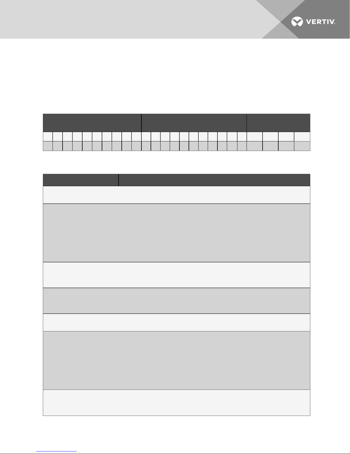
Table 2.2 below describes each digit of the model number.
Table 2.1 DSE Model Number Example
Model Number Digits 1 to 10 Model Details
1 2 3 4 5 6 7 8 9 10 11 12 13 14 15 16 17 18 19 20 21 22 23 24 25
D A 1 2 5 D P 1 A T H 2 0 8 1 1 D 0 B S P 1 2 3 S
Model Number Digits 11 to
14
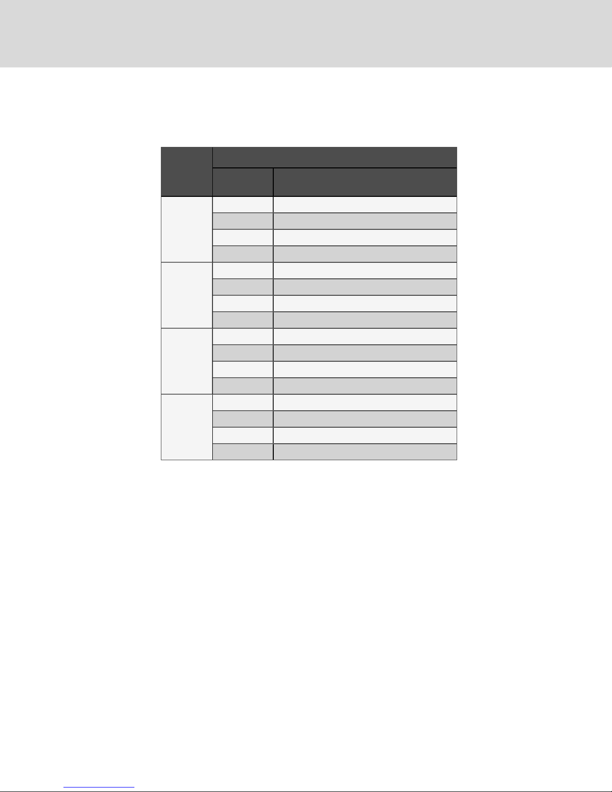
Table 2.2 DSE Model-number Digit Definitions
Digit Description
Digits 1and2 = Product Family
DA = Liebert® DSE
Digit 3, 4, 5 = NominalCoolingCapacity, kW
050 = 50 kW
080 = 80 kW
085 = 85 kW
125 = 125 kW
150 = 150 kW
165 = 165kW
Digit 6 = Air Discharge
D = Downflow
U = Upflow
Digit 7 = System Type
A = Air-cooled
P = Air-cooled, Econ-O-Phase ready
Digit 8 = Air-flow (FanType)
1 = EC plug fans
Digit 9 = Voltage
A = 460V - 3ph -60Hz
B = 575V - 3ph- 60Hz
C = 208V- 3ph -60Hz
D = 230V - 3ph- 60Hz
2 = 380 V- 3ph - 60Hz
M = 380-415 V- 3ph - 50Hz
Digit 10 = CoolingSystem
D = Digital scroll, R-410A
T = Tandem with digital scroll, R-410A
2 Nomenclature and Components 11
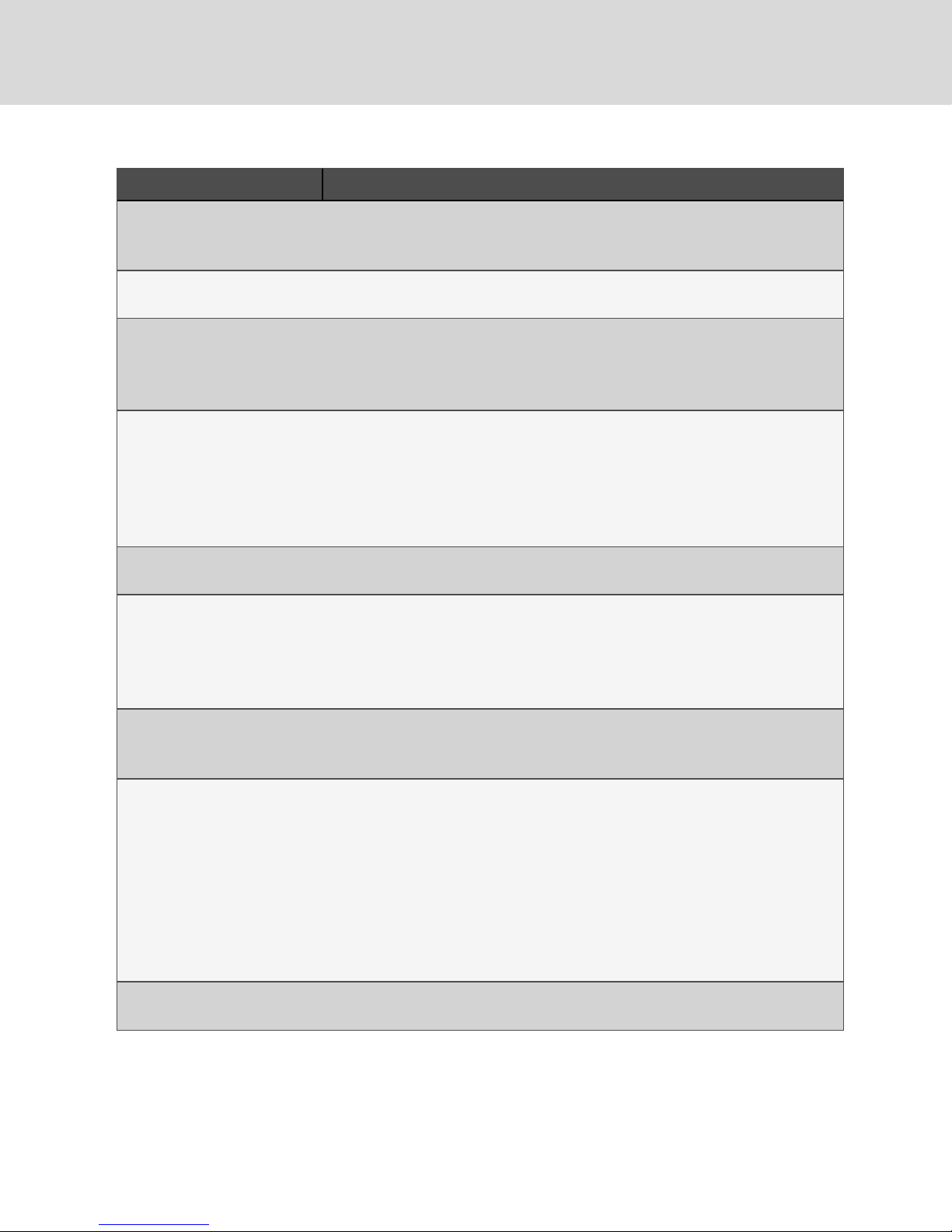
Table 2.2 DSE Model-number Digit Definitions (continued)
Digit Description
Digit 11 = Humidifier
0 = No humidifier
H = Infrared Humidifier
Digit 12 = Display
2 = iCOM (High Definition)
Digit 13 = Reheat
0 = None
1 = Electric reheat, standard capacity
R = Electric reheat, reduced capacity
Digit 14 = Air Filter
8 = MERV 8, 4-in.
9 = MERV 11, 4-in.
A = MERV 13, 4-in.
6 = MERV 11, 2-in. plus MERV 8 pre-filter, 2-in.
C = MERV 13, 2-in. plus MERV 8 pre-filter, 2-in.
Digit 15 = CoilOption
1 = Non-coated coil, indoor unit
Digit 16 = Enclosure Option
1 = Color standard
2 = Color optional
3 = Color standard and IBC/OSHPD bracing
4 = Color optional and IBC/OSHPD bracing
Digit 17 = High-voltage option
L = Locking disconnect
5 = Locking disconnect, with condensate pump
Digit 18 = Option packages
0 = None
L = Option package #1 - low-voltage terminalpackage
H = Reheat and Humidifier lockout
R = Remote humidity contact
C = Option package #1 plus reheat/humidifier lockout
D = Option package #1 plus remote humidifier lockout
E = Option package #1 plus reheat/humidifier lockout plusremote contact
F = Remote humidity contact plus reheat/humidifier lockout
Digit 19 = Monitoring
B = Base comms andconnectivity
12
Vertiv | Liebert® DSE™ Installer/UserGuide
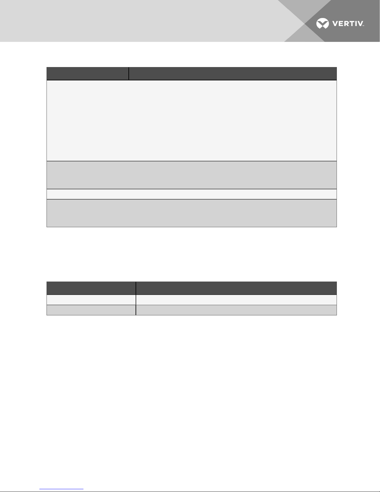
Table 2.2 DSE Model-number Digit Definitions (continued)
Digit Description
Digit 20 = Sensors
0 = None
S = Smoke sensor
H = High-temperature sensor
F = Smoke andHigh-temperature sensors
C = Compressor-overload sensors
A = Compressor, high-temperature sensors
D = Compressor, smoke sensors
K = Compressor, high-temperature, smoke sensors
Digit 21 = Packaging
P = Domestic
C = Export
Digit 22-24 = Factory Configuration Number
Digit 25 = Configuration Code
A = 1
S = SFA
2.2 Component Location
The unit component locations are described in the submittal documents included in the Submittal
Drawings on page93.
The following table lists the relevant documents by number and title.
Table 2.3 Component-location Drawings
Document Number Title
DPN003452 Component Location, Typical, Downflow Models, DA050–DA165
DPN003451 Component Location, Typical, Upflow Models, DA080–DA085
2.3 Cooling Configurations
NOTE: All field-installed piping must comply with applicable local, state and federal codes. Refer to
Piping, for detailed information.
2 Nomenclature and Components 13
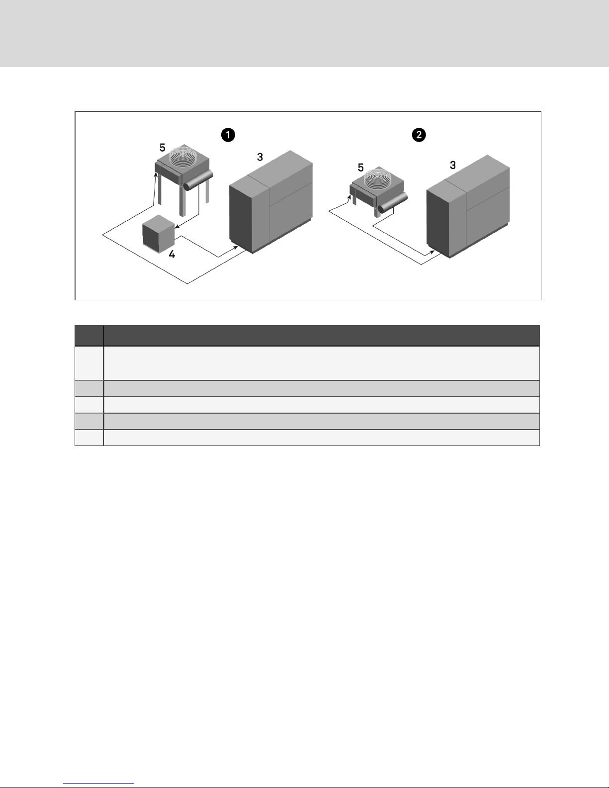
Figure 2.1 DSE with Liebert® MC Condenser
Table 2.4 DSE with MC Condenser Cooling Descriptions
Item D escription
Air-Cooled with EconoPhase Pumping Unit—Allthe features of a standard air-cooled system, with the added benefit of an
1
economizer mode that can be used when the outdoor temperature is cold enough to cool the refrigerant enough to
suspend use of the compressors.
2 Air-cooled— configured as aDX-only system (no economization).
3 Liebert® DSE™Thermal Management System
4 Liebert® EconoPhase™ Pumped-refrigerant Economizer
5 Liebert® MC™ Condenser with DSEreceivers.
14
Vertiv | Liebert® DSE™ Installer/UserGuide
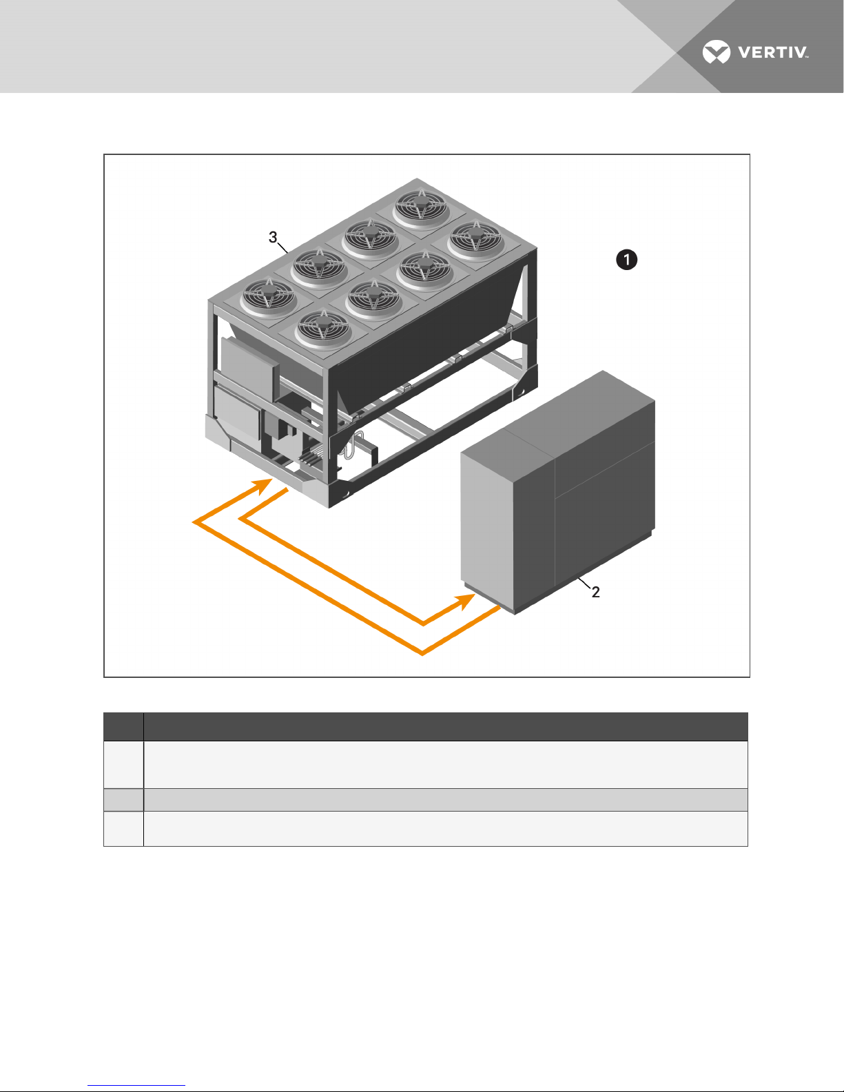
Figure 2.2 DSE with Liebert® MCV Condenser and EconoPhase Pumping Unit
Table 2.5 DSE Air-cooled with MCV Condenser and EconoPhase Pump Cooling Descriptions
Item D escription
Air-cooled with Liebert® MCV™ Condenser with Econo-Phase™ PumpingUnit—All the features ofa standard air-cooled
1
system, with the added benefit of an economizer mode that can be used when the outdoor temperature is cold enough to
cool the refrigerant enough to suspend use of the compressors.
2 Liebert® DSE™Thermal Management System
Liebert® MCV™ Condenser with EconoPhase Pumping unit and DSEreceivers mounted, wired, and piped on a common
3
heat-rejection skidfor ease of job-site deployment.
2 Nomenclature and Components 15

This page intentionally left blank
16
Vertiv | Liebert® DSE™ Installer/UserGuide
3 PRE-INSTALLATION PREPARATIONANDGUIDELINES
NOTE: Before installing unit, determine whether any building alterations are required to run piping,
wiring and ductwork. Follow all unit dimensional drawings and refer to the submittal engineering
dimensional drawings of individual units for proper clearances.
Refer to Table 2.2 on page11, and submittal drawings to determine the type of system being installed
and anticipate building alterations, piping and ductwork needed.
The unit dimensions, pipe-connection locations, and piping schematics are described in the submittal
documents included in the Submittal Drawings on page93.
• Verify that the floor is level, solid and sufficient to support the unit. See 3.6 on page22 for unit
weights.
• Confirm that the room is properly insulated and has a sealed vapor barrier.
• For proper humidity control, keep outside or fresh air to an absolute minimum (less than 5% of
total air circulated in the room).
• Do not install a Liebert® DSE in an alcove or at the end of a long, narrow room.
• Install the units as close as possible to the largest heat load.
• Allow at least the minimum recommended clearances for maintenance and service. See the
appropriate submittal drawings for dimensions.
We recommend installing an under-floor water detection system. Contact your Vertiv representative for
information.
3.1 Planning Dimensions
The unit, floor stand, and plenum dimensions are described in the submittal documents included in the
Submittal Drawings on page93.
The following table lists the relevant documents by number and title.
Table 3.1 Dimension Planning Drawings
Document Number Title
Downflow Units
DPN003533 Cabinet DimensionalData, DA050
DPN004083 Cabinet DimensionalData, DA080 and DA085
DPN003175 Cabinet andPlenum DimensionalData, DA125, DA150 and DA165
Upflow Units
DPN002950 Cabinet Dimensional Data, DA080U and DA085U
Floor Stands
DPN004079 Floorstand DimensionalData, Downflow, DA050
DPN004073 Floorstand DimensionalD ata, D ownflow and Upflow, DA080 and DA085
DPN003177 Floorstand DimensionalData, Downflow, DA125, DA150 and DA165
Plenums
DPN003514 Plenum DimensionalData, Downflow, DA050, DA080 and DA085
DPN004081 Plenum Dimensional Data, Upflow, DA080U andDA085U
3 Pre-installation PreparationandGuidelines 17
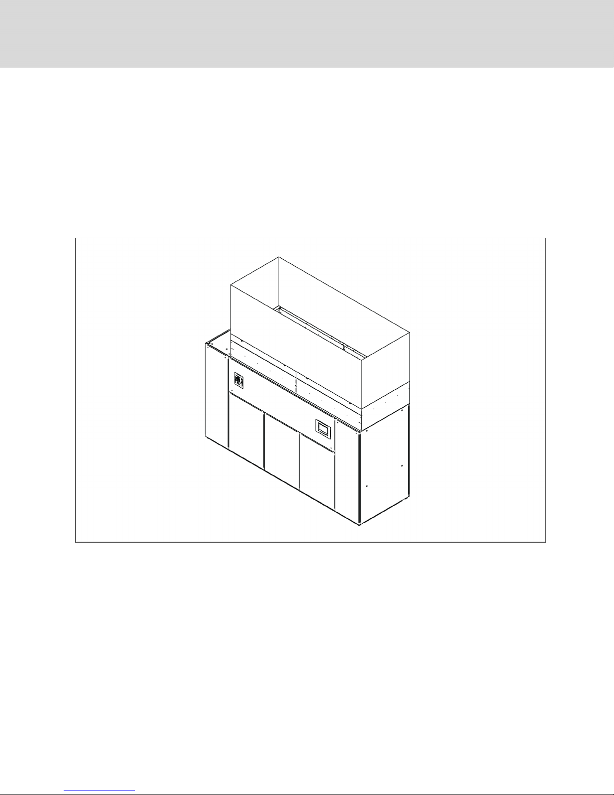
3.2 Air-distribution Considerations for Downflow Units
• Verify that the raised floor has been properly sized for the unit’s airflow and the room is free of
airflow restrictions.
• Perforated floor tiles in the raised floor should ensure minimal pressure loss.
• The raised floor must provide 7-1/2in. (191mm) of clearance.
• A minimum of 24in. (610mm) is required to operate the fans when they are lowered with the
factory-provided jacking mechanism.
• Ensure that there is adequate clearance above the unit for service, such as replacing filters.
• Optional plenums are available for downflow unit ducting.
Figure 3.1 Downflow unit field-installed ducting and plenum ducting for DA125, DA150 and DA165
18
Vertiv | Liebert® DSE™ Installer/UserGuide
3.3 Air-distribution Considerations for Upflow Units
For in-room applications with supply and return grilles, several feet of clearance must be maintained at
the intake and discharge of the unit.
NOTE: Drain traps are qualified to a return duct static of negative 1.5 i.w.g. (-1.5i.w.g).
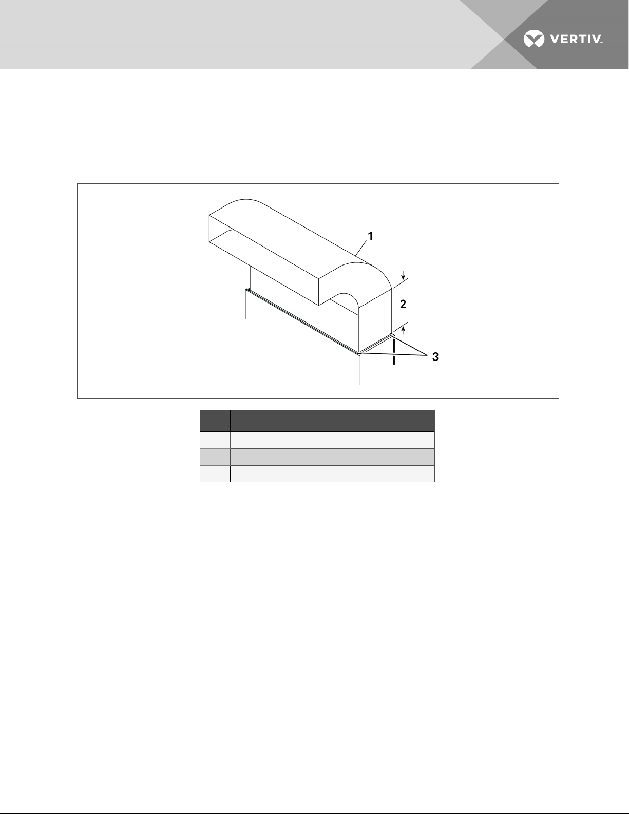
Figure 3.2 Upflow ducting configurations for EC fans for DA080 and DA085
Item D escription
1 Typical ducting. Mayrun to either side.
2 Straight sec tion muse be 2.5 times the depth of blower.
3 Ducting only attached to flanges onprovidedplenum.
NOTE: Follow standard practices in all ductwork.
3.4 Connections and System Setup
• The unit requires a drain, which must comply with all applicable codes. This drain line may
contain boiling water. See Field-installed, Gravity-fed Drain Line Requirements on page32, for
details.
• Three-phase electrical service is required for all models. Electrical service must conform to
national and local electrical codes. See equipment nameplate for details.
• Plan the routing of wiring, piping and ductwork to the unit. Refer to the appropriate piping
connection location drawings, piping schematics, and electrical-connection drawings for your
system in Submittal Drawings on page93.
• If seismic requirements apply, consult your Vertiv representative for information about a
seismic-rated floor stand.
NOTE: Seal openings around piping and electrical connection to prevent air leakage. Failure to do so
could reduce the unit’s cooling performance.
The DSE controls superheat with an electronic expansion valve (EEV). The EEV controller adjusts the
orifice based on suction pressure and temperature. The EEV control will drive the valve to maintain the
superheat setpoint, set in the Liebert® iCOM, using a Proportional, Integral, Derivative (PID) routine. The
PID control values are set at the factory for most applications. These default values PID will allow stable
superheat control of the unit.
3 Pre-installation PreparationandGuidelines 19
For DA080/085 the default PID values must be updated to special PID values when the condenser is
installed at the same level as the evaporator or +10 feet (3m) above the evaporator. The PID control values
(both default and special) are noted Table 3.2 below.
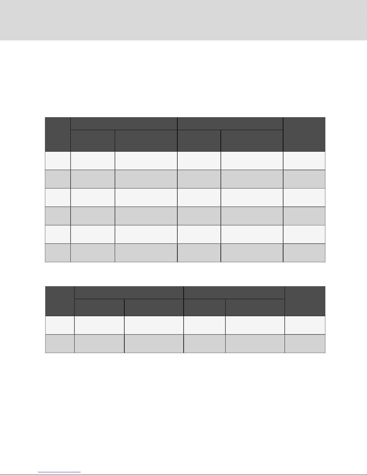
Table 3.2 EEV control values, default and special settings
EEV Settings
Model #
DA050
DA080/085
Downflow
Models
DA080/085
Upflow
Models
DA125/150
DA165
Default Values
E144= MAN E144= MAN
E160 = 0.7 E160 = 1.5
E161= 250 E161= 250
E162 = 4.2 E162 = 2.5
(condenser and evaporator at same level ±10ft[3m])
Special V alues
E144= MAN
E160 = 0.6
E161= 250
E162 = 1.0
E144= MAN
E160 = 2.5
E161= 250
E162 = 4.2
E144= MAN
E160 = 1.8
E161= 250
E162 = 2.5
20
3.5 Operating Conditions
The Liebert® DSE must be operated in a conditioned space within the operating envelope that ASHRAE
recommends for data centers. Operating the DSE outside of this envelope can decrease equipment
reliability. Refer to ASHRAE’s publication, “Thermal Guidelines for Data Processing Environments.”
3.5.1 Cooling, Dehumidification and Humidification
The ASHRAErecommended maximum for return-air temperature is 105°F (40°C) and maximum dew
point is 59°F (15°C). The recommended minimum return-air temperature setpoint for the DSE is 75°F
(24°C).
Operating outside this envelope can decrease equipment reliability.
NOTE: If running in supply-air control, the minimum supply-air setpoint is 64°F (18°C).
Vertiv | Liebert® DSE™ Installer/UserGuide

DA050 Dehumidification Control
The DA050 is designed to maximize sensible cooling not latent cooling loads.
The room load must be at least 37.6kW (74% of unit capacity) to prevent over cooling the room at 85°F
(29°C) return air temperature while in dehumidification mode. If the room load is too low to maintain the
setpoint, the compressor will cycle On and Off. For rooms with multiple units, we recommend performing
dehumidification via Teamwork mode to prevent compressor cycling in case of lightly loaded rooms.
Liebert® DSE units in dehumidification mode might not hold the temperature setpoint unless there is
sufficient room load. This will allow for better dehumidification of the room. The DSE will allow the return air
temperature to run down to 68°F (20°C) regardless of the temperature setpoint during dehumidification
mode of operation.
DA080 and DA085 Dehumidification Control
The DA080 and DA085 will run at lower evaporator temperatures than a DA125. This will result in a higher
percentage of latent cooling than with a DA125 at a given return air temperature. Dehumidification on
DA080 and DA085 is possible with only one circuit running. In dehumidification mode, with one circuit
running, a single stage 15-kW electric reheat (customer option) is available to help offset cooling for lightly
loaded rooms, but over-cooling will be allowed down to 68°F (20°C). If the unit is running in
dehumidification mode with both circuits (compressors) running, the electric reheat is not available to
offset cooling.All DSE units allow the indoor blower to run at a reduced speed during dehumidification
mode to increase the amount of dehumidification being performed.
DA125 Dehumidification Control
The DA125 is designed to maximize sensible cooling not latent cooling loads. With all four compressors
running, no reheat will be available at this dehumidification load point (Stage 4).
The room load must be 94.1kW (74% of unit capacity) to prevent over-cooling the room at 85°F (29°C)
return air temperature. If the room load is too low to maintain the setpoint, the compressors will cycle On
and Off. During Stage 3, with three of the four compressors running, 10 kW of reheat will be available to
offset cooling. During Stage 1 and 2, with one and two compressors running respectively, 30 kW of reheat
is available to offset cooling. For rooms with multiple units, We recommend performing dehumidification in
Teamwork mode to prevent compressor cycling in case of lightly loaded rooms or by having standard DSE
units available to perform dehumidification. DSE units in dehumidification mode might not hold the
temperature setpoint unless there is sufficient room load. This will allow for better dehumidification of the
room. The DSE will allow the return air temperature to run down to 68°F (20°C) regardless of the
temperature setpoint during dehumidification mode of operation.
DA150 and DA165 Dehumidification Control
The DA150 and DA165 are designed to maximize sensible cooling not latent cooling loads. With all four
compressors running, no reheat will be available at this dehumidification load point (Stage 4).
The room load must be 94.1kW (74% of unit capacity) to prevent over-cooling the room at 85°F (29°C)
return air temperature. If the room load is too low to maintain the setpoint, the compressors will cycle On
and Off. During Stage 3, with three of the four compressors running, 10 kW of reheat will be available to
offset cooling. During Stage 1 and 2, with one and two compressors running respectively, 30 kW of reheat
is available to offset cooling. For rooms with multiple units, We recommend performing dehumidification
via Teamwork mode to prevent compressor cycling in case of lightly loaded rooms. DSE units in
dehumidification mode might not hold the temperature setpoint unless there is sufficient room load. This
will allow for better dehumidification of the room. The DSE will allow the return air temperature to run
down to 68°F (20°C) regardless of the temperature setpoint during dehumidification mode of operation.
3.5.2 Heating
The Liebert® DSE is qualified for heating-only operation at temperatures not exceeding 80°F (27°C).
3 Pre-installation PreparationandGuidelines 21
3.5.3 Humidification Control
To prevent the humidifier from running when not required (especially when return air temperatures
exceed 75°F [24°C]), the default control for humidity and dehumidification is based on dew point
temperature, not relative humidity. If this default control is changed, adjust the relative humidity setpoint
based on return air temperature to prevent from over-humidifying the space.
3.6 Shipping Dimensions and Unit Weights
Table 3.3 Downflow unit domestic and export shipping dimensions and weights
Domestic Packaging Export Packaging
Model #
Unit
Ship Weight, lb
(kg)
Shipping D imensions, in.
(mm)
Ship Weight, lb
(kg)
Shipping D imensions, in.
(mm)
Dry Weight, lb
(kg)
DA050*A
DA050*P
DA080*A
DA080*P
DA085*A
DA085*P
DA125*A
DA125*P
DA150*A
DA150*P
DA165*A
DA165*P
2012 (913)
2250 (1021)
2350 (1066)
3450 (1565)
3570 (1619)
3754 (1703)
97 X45 X 82
(2464 X 1143 X 2083)
120 X 45 X 85
(3048 X1143 X2159)
120 X 45 X 85
(3048 X 1143 X 2159)
153 X 54X 85
(3886 X 1372 X 2159)
153 X 54X 85
(3886 X 1372 X 2159)
153 X 54X 85
(3886 X 1372 X 2159)
2182 (990)
2450(1111)
2550 (1157)
3650 (1656)
3770 (1710)
3954 (1794)
97 X 45 X 82
(2464 X 1143 X 2083)
120 X 45 X85.5
(3048 X 1143 X2172)
120 X 45 X85.5
(3048 X 1143 X2172)
153.5 X 54.5 X 85.5
(3899 X 1384 X 2172)
153.5 X 54.5 X 85.5
(3899 X 1384 X 2172)
153.5 X 54.5 X 83.5
(3899 X 1384 X 2121)
Table 3.4 Upflow unit domestic and export shipping dimensions and weights
Domestic Packaging Export Packaging
Model #
DA080U *A
DA080U *P
DA085U*A
DA085U*P
Unit S hip Weight, lb
(kg)
2270 (1030)
2370 (1075)
Shipping d imensions, in.
(mm)
120 X 45 X 85
(3048 X 1143 X 2159)
120 X 45 X 85
(3048 X 1143 X 2159)
Ship Weight, lb
(kg)
2470 (1120)
2570 (1166)
Shipping d imensions, in.
(mm)
120 X 45 X85.5
(3048 X 1143 X 2172)
120 X 45 X85.5
(3048 X 1143 X 2172)
1590( 721)
2200 (998)
2250 (1021)
3465 (1572)
3574 (1621)
3574 (1621)
Dry Weight, lb
(kg)
2150 (975)
2150 (975)
22
Vertiv | Liebert® DSE™ Installer/UserGuide
4 EQUIPMENT INSPECTION AND HANDLING
SAFETY INFORMATION
WARNING! Risk of top-heavy unit falling over. Improper handling can cause equipment
damage, injury or death. Read all of the following instructions and verify that all lifting and
moving equipment is rated for the weight of the unit before attempting to move, lift, remove
packaging from or prepare the unit for installation. Unit weights are specified in Shipping
Dimensions and Unit Weights on page22.
CAUTION: Risk of contact with sharp edges, splinters, and exposed fasteners. Can cause
injury. Only properly trained and qualified personnel wearing appropriate, OSHA-approved PPE
should attempt to move, lift, remove packaging from or prepare the unit for installation.
NOTICE
Risk of passageway interference. Can cause unit and/or structure damage. The unit may be
too large to fit through a passageway while on or off the skid. Measure the unit and passageway
dimensions, and refer to the installation plans prior to moving the unit to verify clearances.
NOTICE
Risk of damage from forklift. Can cause unit damage. Keep tines of the forklift level and at a
height suitable to fit below the skid and/or unit to prevent exterior and/or underside damage.
NOTICE
Risk of improper storage. Keep the unit upright, indoors and protected from dampness,
freezing temperatures and contact damage.
Upon arrival of the unit and before unpacking:
• Verify that the labeled equipment matches the bill of lading.
• Carefully inspect all items for visible or concealed damage.
• Report damage immediately to the carrier and file a damage claim with a copy sent to Vertiv or
to your sales representative.
Equipment Recommended for Handling the Unit:
• Forklift
• Pallet jack
• Piano jacks
• Lift beam
• Slings
• Spreader bars
4.1 Packaging Material
All material used to package this unit is recyclable. Please save for future use or dispose of the
material appropriately.
4 Equipment Inspection and Handling 23
4.2 Handling the Unit while Packaged
If possible, transport the unit with a forklift or pallet jack. If that is not possible, use a crane with slings and
spreader bars that are rated for the weight of the unit.
When using a forklift or pallet jack:
• Ensure that the fork length is suitable for the unit length and, if adjustable, spread to the
widest allowable distance that will fit under the skid.
• When moving the packaged unit, lift the unit from the "HEAVY SIDE" of the unit, and do not lift
the unit any higher than 6in.(152mm). All personnel except those moving the unit must be
kept or more from the unit while it is being moved.
• If the unit must be lifted higher than 6in.(152mm), all personnel not directly involved in
moving the unit must be 20ft (5m) or farther from the unit.
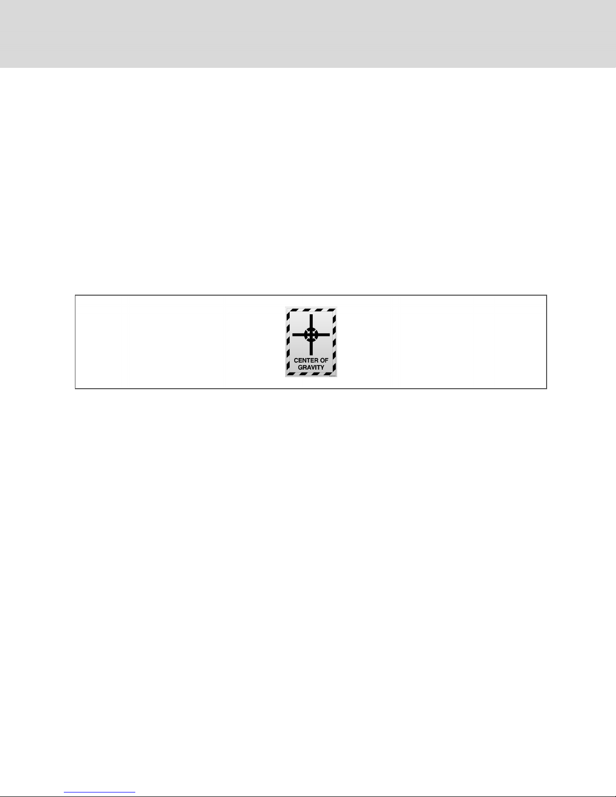
• Always refer to the location of the center-of-gravity indicators when lifting the unit, see Figure
4.1 below.
Figure 4.1 Center-of-gravity indicator
24
Vertiv | Liebert® DSE™ Installer/UserGuide
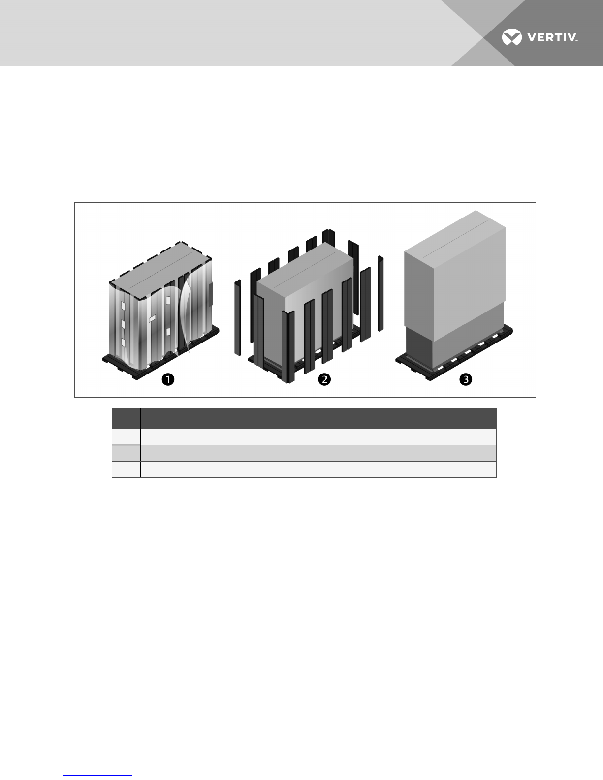
4.3 Unpacking the Unit
1. Remove the exterior stretch wrap packaging and two V-shaped boards from around the unit,
as shown in Figure 4.2 below.
NOTE: The bag may remain in place to protect from dust and to protect the unit panels, or it may be
removed for immediate installation.
2. Remove the bag from the unit when ready to remove the skid and install the unit.
Figure 4.2 Unpacking the Unit
Item D escription
1 Remove exterior wrap from unit
2 Remove corner and side packaging planks
3 Leave the bag onthe unit until readyto install.
4.3.1 Removing the Unit from the Skid with a Forklift
Refer to Figure 4.3 on the next page.
1. Align a forklift with either the front or rear side of the unit.
• Ensure that the tines of the fork lift are locked to the widest location.
• Use the center of gravity indicators on the unit panels when determining the entry points
for the tines. Center of gravity varies per unit size and selected options.
• The tines shall be equally spaced on either side of the center of gravity indicator.
2. Insert the tines of the forklift completely under the base of the unit.
• Ensure that the tines are level, not angled in an upward direction.
• The tines are to be at a height that will allow proper clearance under the unit.
• Ensure that the tines extend beyond the opposite side of the unit.
NOTE: If these steps are not followed, damage may occur to the panels and/or base of the unit.
4 Equipment Inspection and Handling 25
3. Remove the lag bolts from each bracket located around the base, and remove the brackets.
4. Lift the unit off the skid to an elevation point where the skid is not supporting the weight of the
unit and remove the skid from under the unit.
Figure 4.3 Removing from skid with a forklift
Item D escription
1 Align forklift with front or rear ofunit.
2 Insert tines completely under base of unit.
3 Remove lag bolts and brackets
4 Lift unit andremove skid.
4.3.2 Removing the Unit from theSkid Using Rigging
1. Use the center-of-gravity indicators on the unit panels to determine the position of the slings.
• The slings shall be equally-spaced on either side of the center-of-gravity indicator
2. Place the slings and between the bottom rails of the unit and the skid as shown in Figure 4.4
on the facing page.
NOTE: Unit is shown without packaging. These instructions may be followed with or without the outer
packaging in place.
26
Vertiv | Liebert® DSE™ Installer/UserGuide
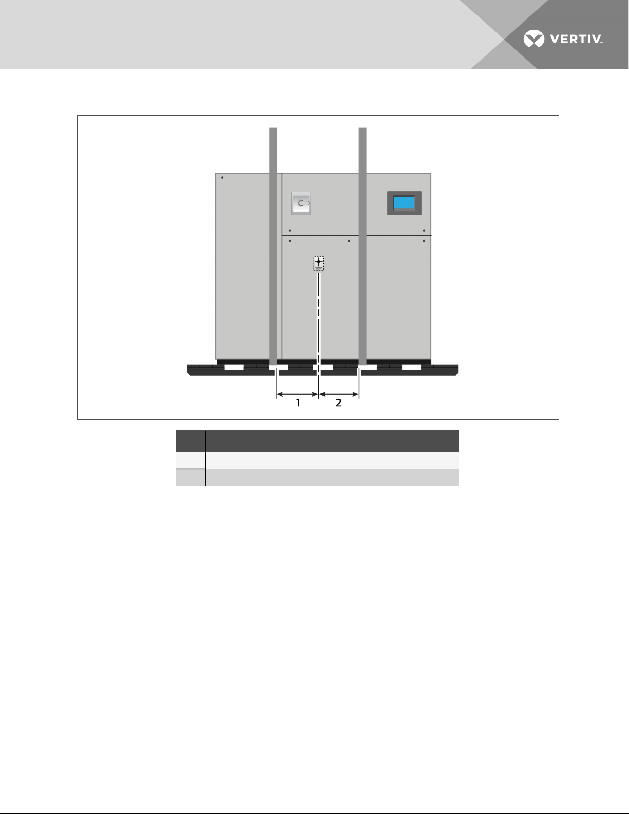
Figure 4.4 Example sling placement
Item D escription
1 Distance between sling and center-of-gravity marker equalto item2.
2 Distance between sling and center-of-gravity marker equalto item1.
4 Equipment Inspection and Handling 27
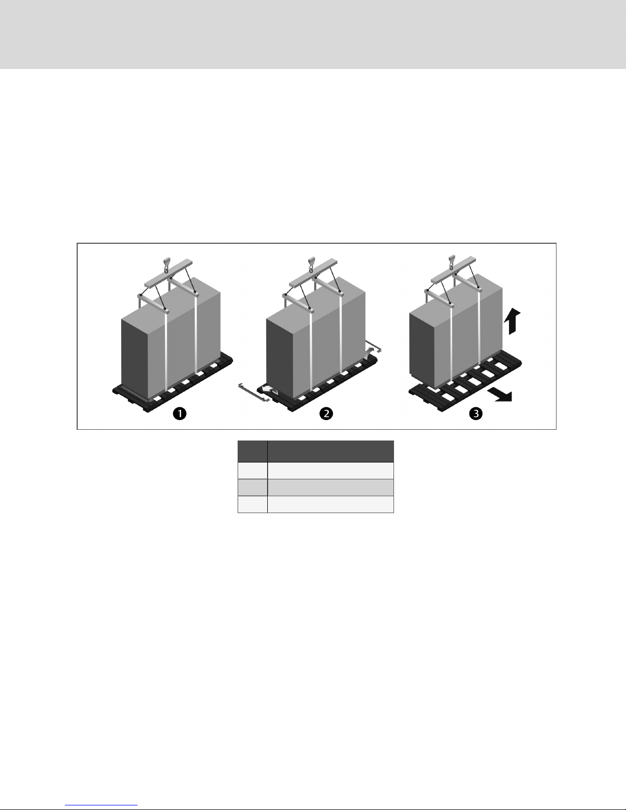
3. Referring to Figure 4.5 below:
• Align the slings as described previously.
• Use spreader bars or equivalent device to ensure proper protection of the unit (Item 1).
• Remove the lag bolts from each bracket located around the base, and remove the
brackets (Item 2).
NOTE: Depending on final installation location, the skid may need to remain under the unit. Therefore,
the lag bolts and brackets would not yet be removed.
• Lift the unit off the skid to an elevation point where the skid is not supporting the weight
of the unit and remove the skid from under the unit (Item 3).
Figure 4.5 Moving unit with rigging
Item D escription
1 Spreader bars and rigging onunit.
2 Remove lag bolts and brackets.
3 Lift the unit and remove the skid.
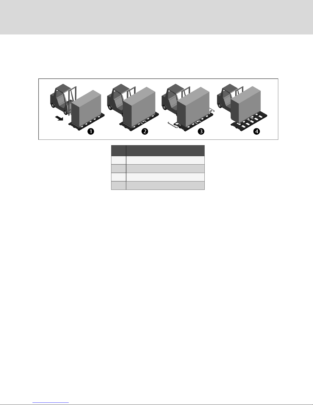
4.3.3 Moving the Unit to the Installation Location Using Piano Jacks
Refer to Figure 4.6 on the facing page.
1. With the unit elevated, position piano jacks at each end of the unit.
2. Lower the unit to a height suitable for the piano jacks, place protective material between the
unit and the piano jacks and straps.
28
Vertiv | Liebert® DSE™ Installer/UserGuide
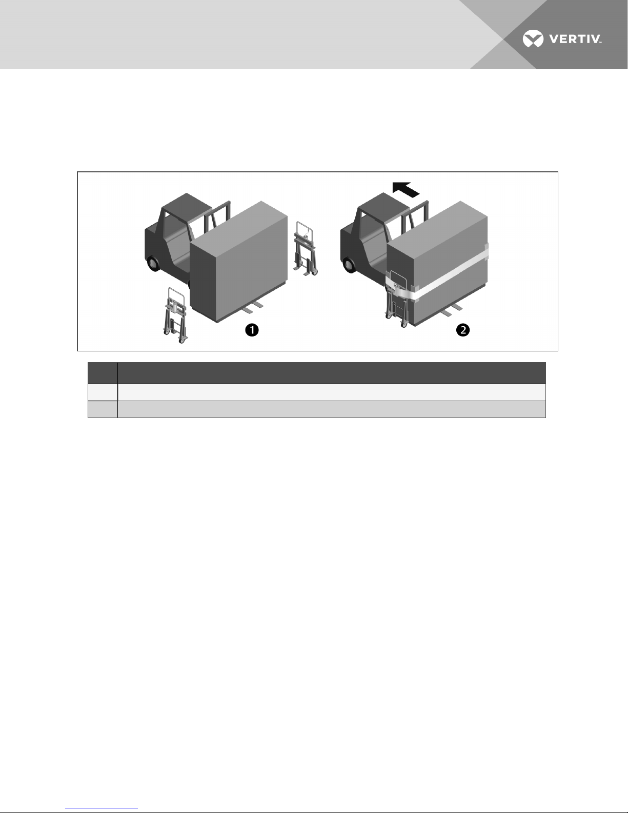
3. With the unit secured to the piano jacks, move the forklift away from the unit.
4. Using the piano jacks, at least two trained personnel can move the unit to the site for
installation.
• For location considerations, refer to Pre-installation PreparationandGuidelines.
Figure 4.6 Moving unit with piano jacks
Item D escription
1 Place piano jacks on each end of the unit.
2 Use padding between unit and straps and, with the unit secured to the piano jacks, move the forklift away from the unit.
4 Equipment Inspection and Handling 29
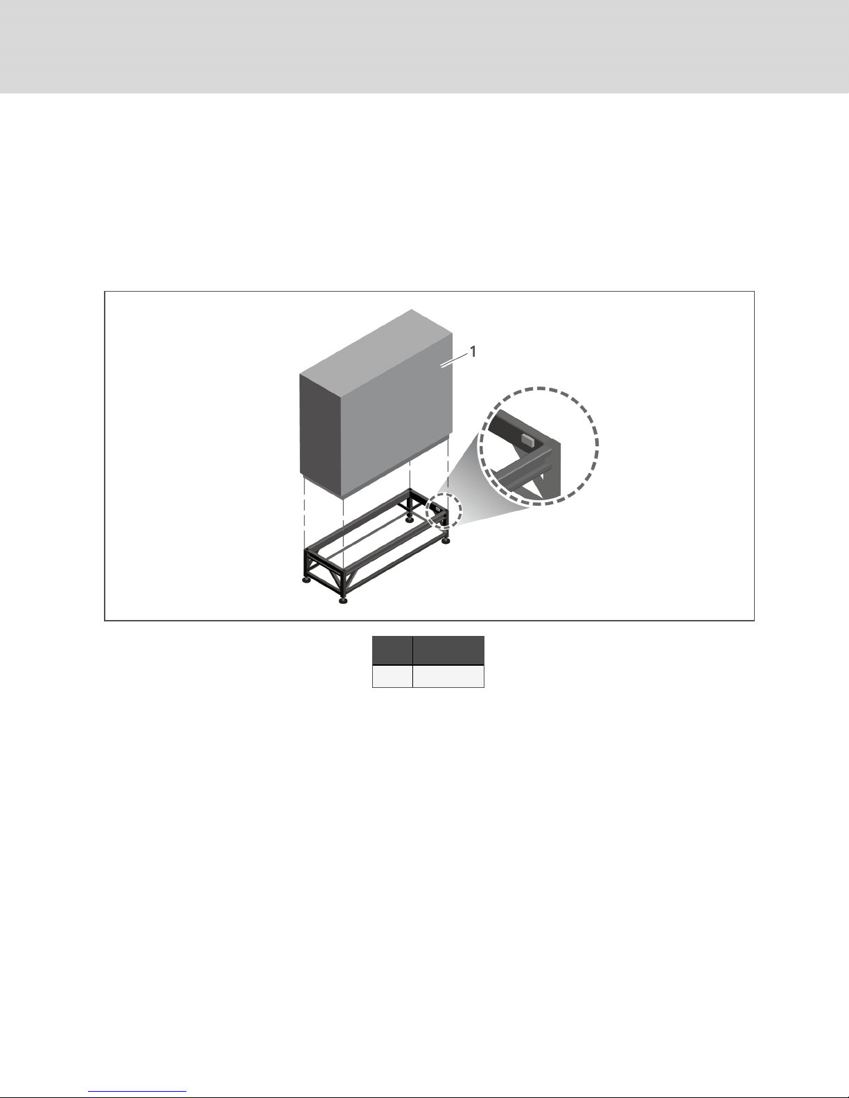
4.4 Placing the Unit on a Floor Stand
Refer to the floor-stand installation sheet, located inside the floor-stand package. Lower the unit onto the
floor stand. Refer to Figure 4.7 below. Be sure to align the welded tabs on top of the floor stand with the
inside of the unit frame base.
NOTE: The floor stand for the units equipped with EC fans is not symmetrical. Its orientation to the
unit is critical for lowering the EC fans. Unless the floor stand is installed in the correct position, the
fans will not lower into the floor stand.
Figure 4.7 Welded tabs on floor stand
30
Item D escription
1 Front of unit
Vertiv | Liebert® DSE™ Installer/UserGuide
 Loading...