

Page 1

Liebert®
DCD™
Installer/User Guide
Page 2

The information contained in this document is subject to change
without notice and may not be suitable for all applications. While
every precaution has been taken to ensure the accuracy and
completeness of this document, Vertiv assumes no responsibility
and disclaims all liability for damages resulting from use of this
information or for any errors or omissions. Refer to other local
practices or building codes as applicable for the correct methods,
tools, and materials to be used in performing procedures not
specifically described in this document.
The products covered by this instruction manual are manufactured
and/or sold by Vertiv. This document is the property of Vertiv and
contains confidential and proprietary information owned by Vertiv.
Any copying, use or disclosure of it without the written permission
of Vertiv is strictly prohibited.
Names of companies and products are trademarks or registered
trademarks of the respective companies. Any questions regarding
usage of trademark names should be directed to the original
manufacturer.
Technical Support Site
If you encounter any installation or operational issues with your product, check the pertinent
section of this manual to see if the issue can be resolved by following outlined procedures.
Visit https://www.VertivCo.com/en-us/support/ for additional assistance.
Vertiv | Liebert® DCD™Installer/UserGuide
Page 3

TABLE OF CONTENTS
1 Important Safety Instructions 5
2 Nomenclature and Components 9
2.1 Model Number Nomenclature 9
2.2 Component Locations 10
3 General Product Information 13
3.1 Product/System Description 13
3.1.1 Cooling Principle 14
3.2 DCD Active with Fan Module 16
4 Pre-installation Preparation and Guidelines 19
4.1 Planning Dimensions 19
4.2 UnitWeights 19
4.3 Room Preparation 19
4.4 Air-flow Considerations 20
4.5 Water-supply Considerations 20
4.5.1 Water Quality Requirements 21
4.5.2 Water Temperature Requirements 22
5 Equipment Inspection and Handling 23
5.1 Storing the Unit 24
5.2 Packaging Material 24
5.3 Handling the Unit while Packaged 24
5.4 Unpacking the Module 25
6 Installation 29
6.1 DCD Frame Preparation 29
6.2 Installing the DCD Frame on a DCM Rack 30
6.2.1 Required Tools 30
6.3 Installing the DCD Door 34
6.4 Installing the DCD Swivel-joint Covers 40
6.5 Reversing the Door Handle 44
6.6 Installing the Active Fan Module 44
6.6.1 Mounting the Active Fan Module on DCD 45
6.6.2 Connecting Supply Power and Sensors 47
7 Piping Considerations and Connections 49
7.1 System Connection Configuration 49
7.1.1 Using Chilled-water Distribution Units 51
7.1.2 Using Open-loop Chilled-water Systems 51
7.2 Connection Methods and Points 51
7.3 Floor Cut-out Dimensions for Units with Bottom Connections 52
7.4 Insulate Piping 52
7.5 Recommended Pipe Sizes 52
7.6 Chilled-water Connection Components 53
Vertiv | Liebert® DCD™Installer/User Guide | 3
Page 4

7.6.1 Strainer 53
7.6.2 Service Valves 53
7.6.3 Balancing Valves 53
7.6.4 Flexible Pipes 54
7.7 Leak Checking 55
7.8 Filling the Unit 55
7.8.1 Bleeding Air from the DCD 56
8 Installation Checklist andSystemFillforStart-up 57
9 Using the DCD Active TFT Display 61
9.1 Main Screen 61
9.1.1 Viewing Fan Status Detail 62
9.1.2 Viewing Exhaust-air Sensor Status 63
9.1.3 Viewing Cabinet Temperature-sensor Status 64
9.2 Settings Menu 65
9.2.1 Temperature Sensors Menu 66
9.2.2 Differential-pressure Regulation 66
9.2.3 Set-up Menu 67
10 Maintenance 69
10.1 General Maintenance 69
Appendices 71
Appendix A: Technical Support and Contacts 71
Appendix B: Specifications 73
Appendix C: Submittal Drawings 83
Vertiv | Liebert® DCD™Installer/User Guide | 4
Page 5

1 IMPORTANT SAFETY INSTRUCTIONS
SAVE THESE INSTRUCTIONS
This manual contains important safety instructions that should be followed during the installation and
maintenance of the Liebert®DCD. Read this manual thoroughly before attempting to install or operate
this unit.
Only qualified personnel should move, install or service this equipment.
Adhere to all warnings, cautions, notices and installation, operating and safety instructions on the unit
and in this manual. Follow all installation, operation and maintenance instructions and all applicable
national and local building, electrical and plumbing codes.
WARNING! Arc flash and electric shock hazard. Open all local and remote electric power
disconnect switches, verify with a voltmeter that power is Off and wear personal protective
equipment (PPE) per NFPA 70E before working with the module. Failure to comply can cause
serious injury or death. Follow all local codes.
WARNING! Risk of heavy module falling. Can cause equipment damage, injury and death. Two
properly-trained and qualified people are required to move and install the module. The DCD™
weighs in excess of 210lb(95kg). Do not leave a DCD™ standing unattended on its side or its
end without adequate support to prevent it from falling over. The module must be supported at
all times or laid flat on protective material until it is installed. Read all instructions before
attempting to move, lift, remove packaging from, or prepare the module for installation. See
Table 4.2 on page19, for unit weights based on model.
WARNING! Risk of improper operation and overpressurization. Can cause equipment or other
property damage, injury and death. Only personnel properly trained and qualified in HVAC
installation or service should installor service this equipment
WARNING! Risk of contact with high-speed, rotating fan impeller blades. Can cause injury or
death. Open all local and remote electric power-supply disconnect switches, verify with a
voltmeter that power is off, and verify that all fan impellers have stopped rotating before
working in the unit cabinet.
CAUTION: Risk of contact with sharp edges, splinters, and exposed fasteners. Can cause
injury. Only properly trained and qualified personnel wearing appropriate, OSHA-approved PPE
should attempt to move, lift, remove packaging from or prepare the unit for installation.
1 Important Safety Instructions
5
Page 6

NOTICE
NOTICE
NOTICE
CAUTION: Risk of improper repair and maintenance. Can cause reduced unit performance,
equipment damage and injury.
All maintenance and repair jobs must be performed by properly trained and qualified personnel.
All actions must be in accordance with regulations and the manufacturer’s instructions. Use
only Vertiv-approved tools and parts for maintenance and repair.
Risk of improper power-supply connection. Can cause equipment damage and loss of warranty
coverage.
Prior to connecting any equipment to a main or alternate power source (for example: back-up
generator systems) for start-up, commissioning, testing, or normal operation, ensure that these
sources are correctly adjusted to the nameplate voltage and frequency of all equipment to be
connected. In general, power-source voltages should be stabilized and regulated to within
±10% of the load nameplate nominal voltage. Also, ensure that no three-phase sources are
single-phased at any time.
Risk of passageway interference. Can cause unit and/or structure damage. The unit may be
too large to fit through a passageway while on or off the skid. Measure the unit and passageway
dimensions, and refer to the installation plans prior to moving the unit to verify clearances.
NOTICE
Risk of damage from forklift. Can cause unit damage. Keep tines of the forklift level and at a
height suitable to fit below the skid and/or unit to prevent exterior and/or underside damage.
Risk of improper storage. Keep the unit upright, indoors and protected from dampness,
freezing temperatures and contact damage.
6
Vertiv | Liebert® D CD™Installer/User G uide
Page 7

NOTICE
Risk of piping-system corrosion and freezing fluids. Can cause leaks resulting in equipment
and very expensive building damage. Cooling coils and piping systems are at high risk of
freezing and premature corrosion. Fluids in these systems must contain the proper antifreeze
and inhibitors to prevent freezing and premature coil and piping corrosion. The water or
water/glycol solution must be analyzed by a competent local water treatment specialist before
start up to establish the inhibitor and antifreeze solution requirement and at regularly
scheduled intervals throughout the life of the system to determine the pattern of inhibitor
depletion.
The complexity of water/glycol solution condition problems and the variations of required
treatment programs make it extremely important to obtain the advice of a competent and
experienced water treatment specialist and follow a regularly scheduled coolant fluid system
maintenance program.
Water chemistry varies greatly by location, as do the required additives, called inhibitors, that
reduce the corrosive effect of the fluids on the piping systems and components. The chemistry
of the water used must be considered, because water from some sources may contain corrosive
elements that reduce the effectiveness of the inhibited formulation. Sediment deposits prevent
the formation of a protective oxide layer on the inside of the coolant system components and
piping. The water/coolant fluid must be treated and circulating through the system
continuously to prevent the buildup of sediment deposits and or growth of sulfate reducing
bacteria.
Proper inhibitor maintenance must be performed in order to prevent corrosion of the system.
Consult glycol manufacturer for testing and maintenance of inhibitors.
Commercial ethylene glycol, when pure, is generally less corrosive to the common metals of
construction than water itself. It will, however, assume the corrosivity of the water from which it
is prepared and may become increasingly corrosive with use if not properly inhibited.
We recommend installing a monitored fluid-detection system that is wired to activate the
automatic-closure of field-installed coolant-fluid supply and return shut-off valves to reduce
the amount of coolant-fluid leakage and consequential equipment and building damage. The
shut-off valves must be sized to close-off against the maximum coolant-fluid system pressure
in case of a catastrophic fluid leak.
1 Important Safety Instructions
7
Page 8

NOTICE
NOTICE
Risk of clogged or leaking drain lines and leaking water-supply lines. Can cause equipment and
building damage.
This unit requires a water drain connection. Drain lines must be inspected at start-up and
periodically, and maintenance must be performed to ensure that drain water runs freely
through the drain system and that lines are clear and free of obstructions and in good
condition with no visible sign of damage or leaks. This unit may also require an external water
supply to operate.
Improper installation, application and service practices can result in water leakage from the
unit. Water leakage can result in catastrophic and expensive building and equipment damage
and loss of critical data center equipment.
Do not locate unit directly above any equipment that could sustain water damage.
We recommend installing a monitored fluid-detection system to immediately discover and
report coolant-fluid system and condensate drain-line leaks.
Risk coil and piping rupture. Can cause equipment damage and major fluid leaks resulting in
serious building damage, expensive repair costs and costly system down time.
Thermal expansion of the cooling fluid without means of expansion can cause the coil and
piping to rupture, spilling cooling fluid in the conditioned space. This can be caused, among
other ways, by closing the ball valves on both the supply and the return pipes. Always allow for
thermal expansion either by leaving at least one of the valves open or by opening the DCD™
bleed valve.
NOTE: This document is intended to be used together with site-specific documentation and
documentation for other parts of the system.
8
Vertiv | Liebert® D CD™Installer/User G uide
Page 9
2 NOMENCLATURE AND COMPONENTS
This section describes the model number for Liebert® DCD units and components.
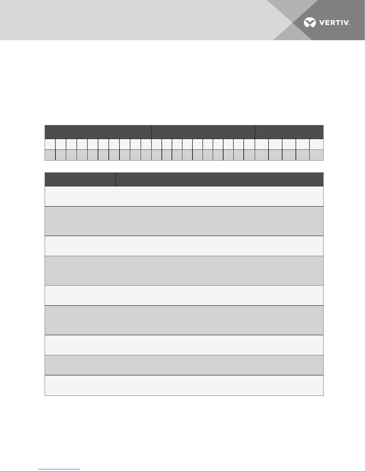
2.1 Model Number Nomenclature
Table 2.2 on the next page describes each digit of the model number.
Table 2.1 Liebert DCD Model-number Example
Model Number Digits 1 to 10 Model Det ails Model Number Digits 11 to 14
1 2 3 4 5 6 7 8 9 10 11 12 13 14 15 16 17 18 19 20 21 22 23 24 25
D C D 3 5 A 6 0 3 0 0 0 0 0 0 G 0 0 0 0 S A 0 0 2
Table 2.2 Model-number Digit Definitions for Liebert DCD
Digit Description
Digits 1, 2, 3 = the base unit
DCD = Data Center Door
Digit 4, 5 = Nominal Capacity
35 = 35kW
50 = 50kW
Digit 6 = Rack Height
A = 42U, 78-6/8 in. (2000mm)
Digit 7 = Rack Width
6 = 23-5/8 in. (600mm), onlyavailable on 35 models.
8 - 32-1/2 in. (800mm)
Digit 8 = Cabinet Type
0 = No aluminum frame
Digit 9 = Chilled-water Connection/Hinge Position
1 = Top connection/Hinges left
3 = Bottom connection/Hinges left
Digit 10 = Options
0 = None
Digits 11 to 15 = Not Used
0 = No options
Digit 16 = Color
G = RAL 7021 (dark gray)
2 Nomenclature and Components
9
Page 10
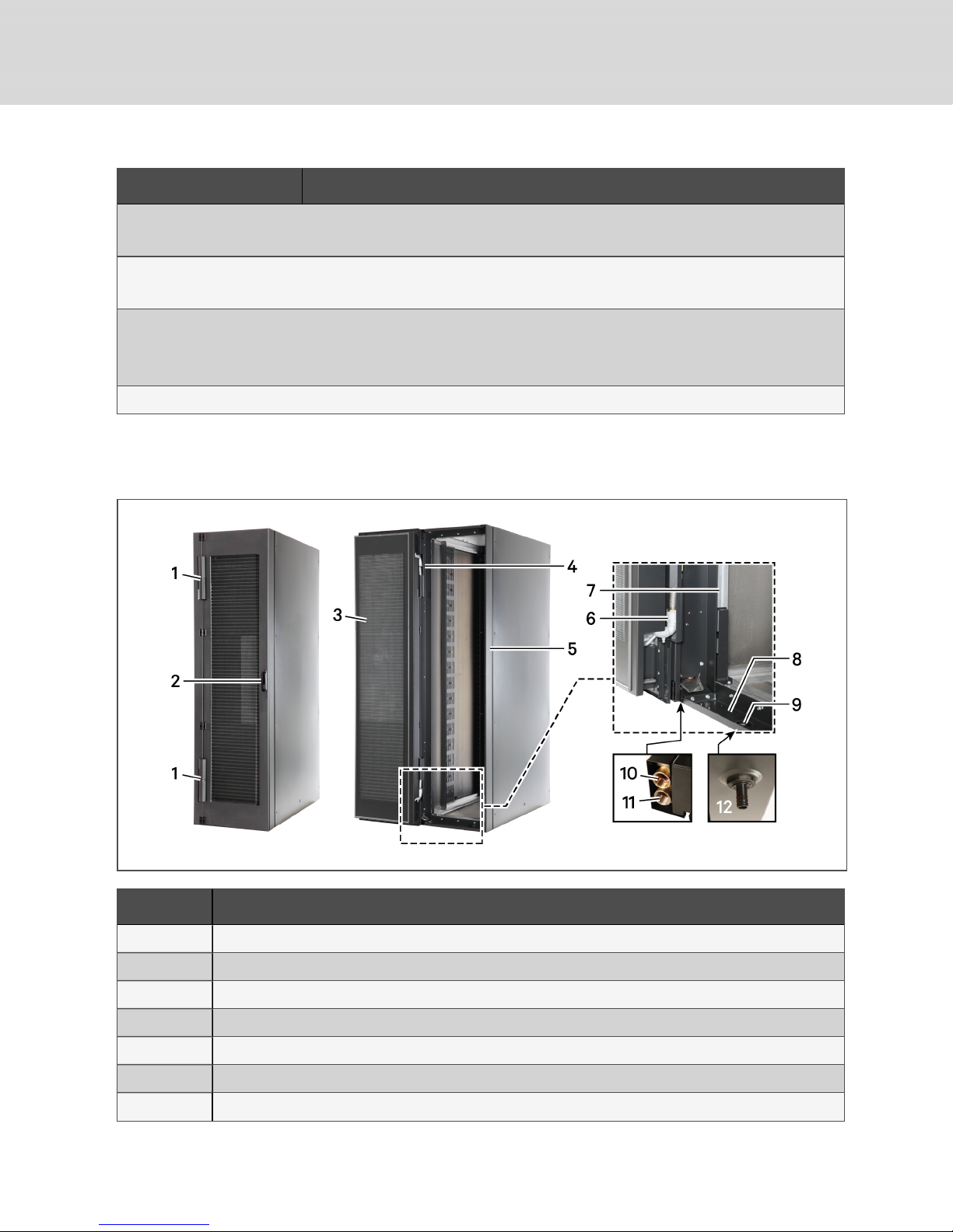
Table 2.2 Model-number Digit Definitions for Liebert DCD (continued)
Digit Description
Digits 17 to 20 = Not Used
0 = No options
Digit 21 = Packaging Type
S = Seaworthy (air freight), Long distance (wooden crate)
Digit 22 = SFA (SpecialFeatures)
A = Standard, no SFA
X = SFA(s) included
Digits 23 to 25 = Revision Identifier
2.2 Component Locations
Figure 2.1 Liebert DCD Component locations
Item Description
1 Upper and Lower swivel joints
2 Door handle
3 Door
4 Upper piping
5 DCD frame
6 Lower Piping
7 Aluminum profile
10
Vertiv | Liebert® D CD™Installer/User G uide
Page 11
Item Description
8 Condensate tray
9 Condensate drain plug
10 Chilled-water outlet
11 Chilled-water inlet
12 Condensate-hose adapter (on the bottom of the unit)
2 Nomenclature and Components
11
Page 12

This page intentionally left blank
12
Vertiv | Liebert® D CD™Installer/User G uide
Page 13
3 GENERAL PRODUCT INFORMATION
3.1 Product/System Description
The Liebert® DCD™ is an air-water heat exchanger that is integrated into the rear door of a server rack.
The DCD™ meets the requirements of the EN 60950 standard. The design allows installation on the back
of a server cabinet and maintains access to the back of the servers while the chilled water connections
remain stationary. The DCD35 is suitable for absorbing up to 35-kW heat loads from server racks 24in.
(600mm) x 42U. The DCD50 is suitable for absorbing up to 50-kW heat loads from server racks 31.5in.
(800mm) x 42U. It can be configured so that no heat is released in the installation area with proper
cabinet sealing.
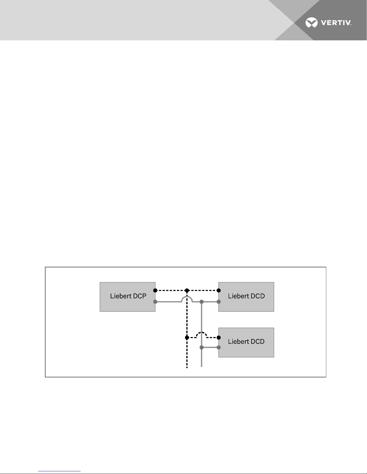
Heat produced by internal components (for example, servers), is reliably removed by the door with a builtin chilled water system or a chilled-water distribution unit, such as the Liebert® DCP™ (see Figure 3.1
below). A chilled-water distribution unit provides these benefits:
• Isolates the building’s chilled-water circuit from the chilled-water circuit in the data center. The
DCP circulates chilled water to DCD while preventing condensation by maintaining the water
temperature above the room dew point.
• Ensures the proper flow rate to the DCD. This is critical to achieve and maintaining the needed
capacity.
• Minimizes the possibility of a leak within the data center by separating the data center from
the building chilled-water circuit. Should a leak occur within the data center, the volume of
water is limited to the amount in the secondary piping system instead of the amount in the
entire-building chilled-water system.
Figure 3.1 Generic piping layout
Room air is drawn in through the front of the rack and picks up heat from the servers. Cooling occurs
when the server exhaust air passes through the DCD™ heat exchanger (see Figure 3.2 on the next
page). The air is moved through the heat exchanger by the server fans.
3 General Product Information
13
Page 14
The DCD™ is not expected to produce any condensation because of its location within the conditioned
space and connected to a Liebert® DCP or if the chilled-water temperature is maintained above the dew
point, A condensate pan is provided as a precaution. It has a drain fitting to allow any condensate to be
emptied.
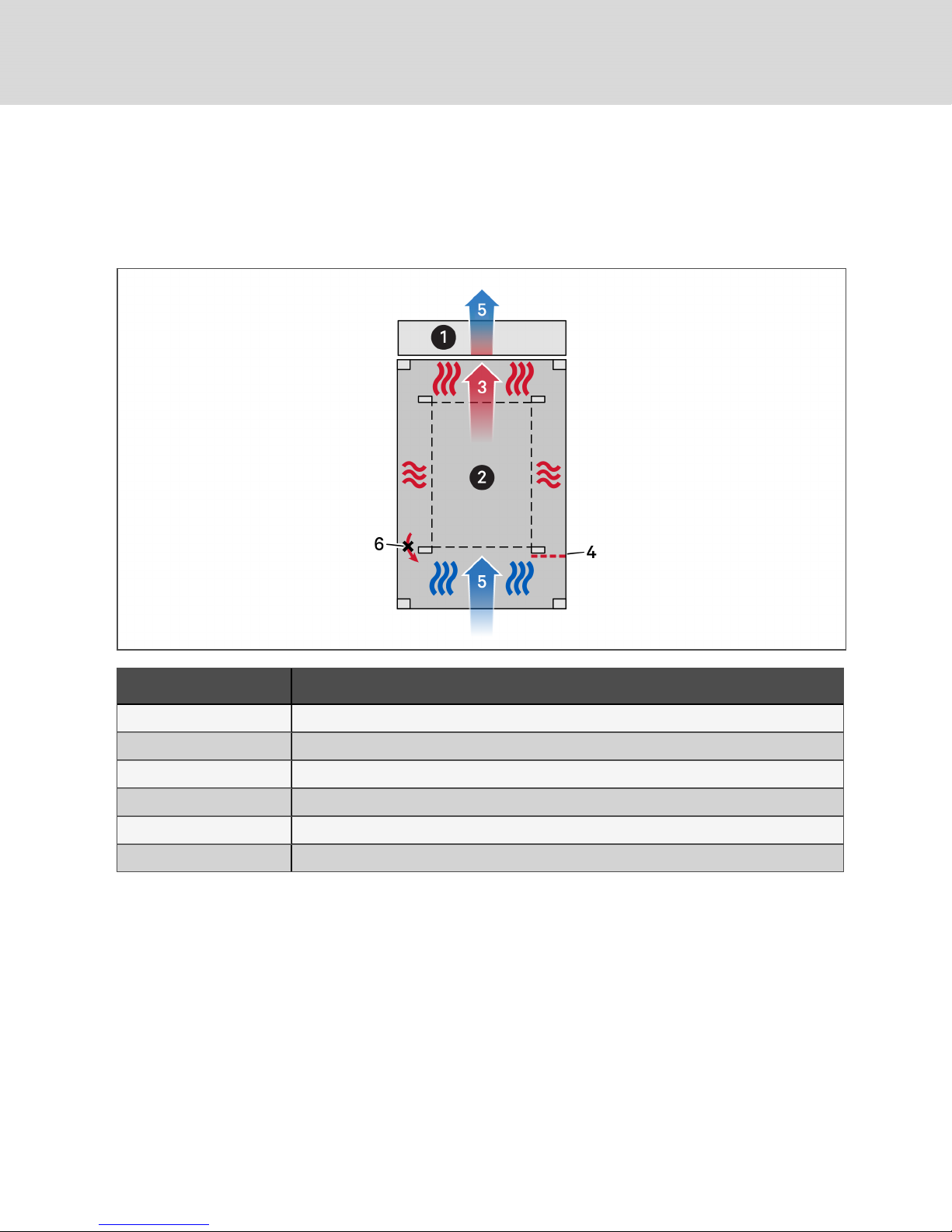
Figure 3.2 Top view of air flow and cooling of rack with Liebert DCD
Item Description
1 DCD unit
2 Server
3 Warm air
4 Air barrier
5 Coldair
6 Recirculation prevented
3.1.1 Cooling Principle
The server fans force air heated by the rack equipment through the unit’s air-water heat exchanger
where it is cooled. The air-side pressure-drop flow-rate dependency curve is shown in Figure B.7 on
page77.
14
Vertiv | Liebert® D CD™Installer/User G uide
Page 15
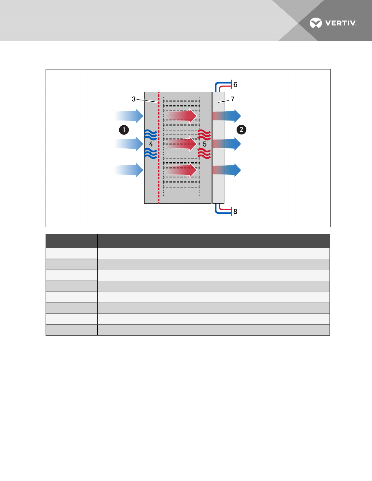
Figure 3.3 Cooling principle shown in side-view diagram of rack/DCD
Item Description
1 Air intake
2 Air outlet
3 Air barrier
4 Cold air
5 Warm air
6 Top cooling-water connections
7 DCD unit
8 Bottom cooling-water connections
NOTE: Before using the DCD™, check the system and rack equipment and make sure that they match
hydraulically. In particular, the server fans must be able to generate sufficient pressure to drive the air
through the DCD™.
NOTE: Cooling-water supply and return connections are supplied at each end of the DCD™, but
connections must be made at only one end, either the top or the bottom of the DCD™.
NOTE: In case of chilled-water supply-system failure, the cooling is provided either by adjacent DCD™
modules and/or the room cooling system. In this example, the equipment waste heat is released into
the room.
3 General Product Information
15
Page 16
3.2 DCD Active with Fan Module
The DCD Active is an option which includes a fan module to be attached to the DCD cooling coil. See
Table 3.1 on the facing page, for the physical and environmental data and requirements of the module.
The active-fan module operates by measuring pressure differential between ambient pressure and the
pressure inside the cabinet and modulating fan speed to reach a predefined pressure setpoint. The
default setpoint is 0-Pa pressure differential. There are two versions of active-fan module:
• Standard—actively maintains a 0-Pa pressure differential by modulating fan speed, and
indicates operating status via a green "operating"LED and a red "disturbance" LED.
• TFT—includes a touch-screen display and temperature sensors for precise control of the
pressure differential and fan speed based on pressure and temperature readings. See Using
the DCD Active TFT Display on page61, for details.
Table 3.1 DCD Active Specifications
Item Specification
Power Supply Single 110/230V A/B 230V A/B 110V
Operating voltage 95 - 264 V, 47 - 63 Hz 190 - 264 V, 47 - 63 Hz 95 - 264 V, 47 - 63 Hz
Rated current 5/11 A (110/230 V) 5A 11A
Fuses 10/12A T 10AT 12AT
ExternalTemperature Sensors
Output voltage 5 V
Output current maximum 5mA
Communication type OneWire
Usable types
IP Interface
Communication type RS-485, 3.3V
Data rate 9600 baud
PhysicalData
Dimensions (LxWxH)DCD35, in. (mm) 76.9 x16.5x4.9 (1954 x 420 x 125)
Dimensions (LxWxH)DCD50, in. (mm) 76.9x 22 .8X4.9 (1954 x 579 x 125)
Weight DCD35, lb(kg) 77(35)
Weight DCD50, lb(kg) 88.2 (40)
Degree of protection IP2 0
Degree of containment 2
Ambient Conditions
Operating temperature 50 to 104°F (10 to 40°C)
Liebert® SN-T
Maxim DS28EA00, DS18B20
Storage temperature –13 to 176°F (–25 to 80°C)
Relative humidity 0 to 95% non-c ondensing
16
Vertiv | Liebert® D CD™Installer/User G uide
Page 17
Table 3.1 DCD Active Specifications (continued)
Item Specification
Altitude above sea level, ft (m) maximum 6,562 (2000)
Pressure Connection
Operating pressure, –1.005 to 1.005 inAq(–250 to 250Pa)
Maximum pressure permitted ± 14.5psi (1bar)
Tolerance 3% of the measured value ± 0.0008 inAq (0.2Pa)
Working gases Air, Nitrogen
Hose—outer diameter, in. (mm) 0.24 (6)
3 General Product Information
17
Page 18

This page intentionally left blank
18
Vertiv | Liebert® D CD™Installer/User G uide
Page 19
4 PRE-INSTALLATION PREPARATION AND GUIDELINES
The Liebert DCD attaches to the rear of a computer cabinet with side panels. See the dimensional-data
drawings in the Submittal Drawings on page83.
NOTE: The cooling with Liebert DCD works only if a strict air separation exists between server cold air
intake and server warm air outlet. Unused rack spaces must be blocked with blanking plates. All
bushings (network cables, piping, etc.) must be sealed to prevent air leakage. Racks must have side
panels. The tops and bottoms of the racks must be sealed.
4.1 Planning Dimensions
Refer to site-specific drawings for exact placement. Efficient cooling depends on proper equipment
placement, proper use of plates in any voids in the rack and good cable management.
Ensure that there is 25.6-in.(649mm) clearance in the rear to allow the door to open fully.
The unit dimensions are described in the submittal documents included in the Submittal Drawings on
page83.
The following table lists the relevant documents by number and title.
Table 4.1 Dimension Planning Drawings
Document Number Title
DPN004112 Dimensional Data, DCD35
DPN004113 DimensionalData, DCD50
4.2 UnitWeights
Table 4.2 Liebert DCD unit weights
Model Number Weight, lb (kg)
DCD35 210 (95)
DCD50 230 (104)
4.3 Room Preparation
The room should be well-insulated and must have a sealed vapor barrier. The vapor barrier in the ceiling
and walls can be a polyethylene film. Paint on concrete walls and floors should contain either rubber or
plastic.
NOTE: The vapor barrier is the most important factor in maintaining environmental control in the
conditioned space.
Outside or fresh air should be kept to a minimum when temperature and humidity must be tightly
controlled. Outside air adds to the site’s cooling, heating, dehumidifying and humidifying loads. Doors
must be properly sealed to minimize leaks and must not contain ventilation grilles.
4 Pre-installation Preparation and Guidelines
19
Page 20
4.4 Air-flow Considerations
The server fans draw air into the rack where the equipment heats it. The server fans force the heated air
across the DCD™ coil. The DCD™ has a low air-side pressure drop, similar to a rack with perforated doors.
Figure 4.1 Generic airflow diagram—enclosure/rack shown from side
Item Description
1 Front of rack
2 Rear of rack
3 DCD
4 Cooling water connections
5 Criticalequipment
NOTE: To provide optimal cooling, strict separation between the hot and cold air must exist within the
rack and all the bushings (network cables, piping, etc.) must be sealed to prevent air leakage. Air
bypass and recirculation can severely reduce the cooling effectiveness of the DCD™. Install blanking
plates in any voids in the rack to prevent air bypass and air recirculation. Keep the coils clear of any
obstructions that may block the airflow. Contact the factory for further information. Refer to the user
manual supplied with the rack on which the DCD™ is mounted.
4.5 Water-supply Considerations
For reliable function of the DCD™, chilled water must be available in an appropriate amount, of the
required quality, and at the appropriate temperature and pressure.
20
Vertiv | Liebert® D CD™Installer/User G uide
Page 21
4.5.1 Water Quality Requirements
To safeguard the maximum lifetime of air/water heat exchangers, the water used for chilling purposes
must meet the VGB Chilled Water Guidelines (VGB-R 455 P). The chilled water used must be soft enough
to prevent deposits, but it must not be too soft because that would lead to corrosion of the heat
exchanger.
Table 4.3 below, lists the most important impurities and measures for their removal.
Table 4.3 Water Impurity
Water Impurity or Condition Corrective Method
Particles (dp < 0.3 mm) Filter the water
Excessive hardness Soften the water by ion exchange
Moderate level of particles and hardeners Add dispersion or stabilization agents
Moderate level of chemicalimpurities Add deadening agents and inhibitors
Biologicalimpurities (bacteria and algae) Add biocides
We recommend treating water to it get as closest as possible to the values in Table 4.4 on the next page.
Table 4.4 Hydrological data
HydrologicalData
Recommended
Purity Levels
pH values (7 - 10,5)
Carbonate hardness (3 - 8) °dH
Free carbon dioxide (8 - 15) mg/dm3
Combined carbon dioxide
Aggressive carbon dioxide
Sulfides
Oxygen
Chloride ions
Sulphate ions
Nitrates and nitrites
COB
Ammonia
Iron
Manganese
8 - 15mg/dm
0mg/dm
< 10mg/dm
< 50mg/dm
< 250mg/dm
< 10mg/dm
< 7mg/dm
< 5mg/dm
< 5mg/dm
< 0.2mg/dm
< 0.2mg/dm
3
3
3
3
3
3
3
3
3
3
3
Conductivity < 30S/cm
Solid residue from evaporation
4 Pre-installation Preparation and Guidelines
< 500mg/dm
3
21
Page 22
Table 4.4 Hydrological data (continued)
HydrologicalData
Potassium manganese consumption
Suspended matter
PartialFlow Cleaning Recommended
FullFlow Cleaning
Recommended
Purity Levels
< 25mg/dm
< 3mg/dm
3 -15 mg/dm
> 15mg/dm
3
3
3
3
4.5.2 Water Temperature Requirements
The cold water supply temperature must be higher than the dew point temperature of the cold space.
Failure to maintain the cold water supply temperature above the room dew point will result in
condensation. The DCD™ provides only for sensible cooling. You must avoid dehumidification of the room
by the DCD™. The built-in condensate tray with condensate drain is designed only for a short-term
condensation.
Table 4.5 Application conditions
Operating Ambient Temperature 50°F - 95°F (10°C - 35°C) (Other Temperatures on Request)
Maximum Absolute Air Humidity on Site 8g/kg
Chilled Water Temperature Intake 53.6°F (12°C) Other Temperatures on Request
Chilled Water Temperature Outlet 64.4°F (18°C) Other Temperatures on Request)
Water Temperature Difference 10.8°F (6°K)
Use of Glycol On Request (Not Rec ommended)
Chilled Water Connection Rack - Rear Side (Top or Bottom Connection)
Condensate TrayDrain Connection Rack - Rear Side; 5/8"
Maximum Operating Pressure 145psi (10bar)
22
Vertiv | Liebert® D CD™Installer/User G uide
Page 23

5 EQUIPMENT INSPECTION AND HANDLING
SAFETY INFORMATION
WARNING! Risk of top-heavy unit falling over. Improper handling can cause equipment
damage, injury or death. Read all of the following instructions and verify that all lifting and
moving equipment is rated for the weight of the unit before attempting to move, lift, remove
packaging from or prepare the unit for installation. Unit weights are specified in Table 4.2 on
page19.
CAUTION: Risk of contact with sharp edges, splinters, and exposed fasteners. Can cause
injury. Only properly trained and qualified personnel wearing appropriate, OSHA-approved PPE
should attempt to move, lift, remove packaging from or prepare the unit for installation.
NOTICE
Risk of passageway interference. Can cause unit and/or structure damage. The unit may be
too large to fit through a passageway while on or off the skid. Measure the unit and passageway
dimensions, and refer to the installation plans prior to moving the unit to verify clearances.
NOTICE
Risk of damage from forklift. Can cause unit damage. Keep tines of the forklift level and at a
height suitable to fit below the skid and/or unit to prevent exterior and/or underside damage.
NOTICE
Risk of improper storage. Keep the unit upright, indoors and protected from dampness,
freezing temperatures and contact damage.
NOTICE
Risk of a leaking coil due to freezing during improper storage. Can cause equipment and
serious building damage.
The heat exchanger and the supply pipes must be cleared of any water before the unit is
stored, either before storage or after removal from a cabinet. Compressed air can be used to
remove the water. Remove all the vents and the screws before storing.
Upon arrival of the unit and before unpacking:
• Verify that the labeled equipment matches the bill of lading.
• Carefully inspect all items for visible or concealed damage.
• Report damage immediately to the carrier and file a damage claim with a copy sent to Vertiv or
to your sales representative.
Equipment Recommended for Handling the Unit:
• Forklift
• Pallet jack
5 Equipment Inspection and Handling
23
Page 24

5.1 Storing the Unit
• Keep the unit in its original packaging, protected from the weather and in dry conditions.
• Protect the unit’s working parts from sand, rain, dust and other particles and contaminants.
• Store at temperatures between -22°F and +122°F (-30°C and +50°C). The chilled-water circuit
must be empty during storage.
• After storage for a year or longer, the water-bearing hinges must be inspected for functionality.
• Remove all packaging before starting the unit.
• Chilled-water connections are not load-bearing. Do not use the connections as handles.
• When transporting the unit, always make sure the device is properly fastened and secured
against slipping.
NOTICE
Risk of a leaking coil due to freezing during improper storage. Can cause equipment and
serious building damage.
The heat exchanger and the supply pipes must be cleared of any water before the unit is
stored, either before storage or after removal from a cabinet. Compressed air can be used to
remove the water. Remove all the vents and the screws before storing.
5.2 Packaging Material
All material used to package this unit is recyclable. Please save for future use or dispose of the
material appropriately.
5.3 Handling the Unit while Packaged
Transport the unit with a forklift or pallet jack.
When using a forklift or pallet jack:
• If multiple units are delivered, they ship on a pallet with up to 4 modules, and a pallet jack is
required to move these to the installation location.
• Make sure that the fork tine length is suitable to move the packaged module.
• When moving the packaged unit, do not lift the unit any higher than 6in.(152mm). All
personnel except those moving the unit must be kept 20ft(5m) or more from the unit while it
is being moved.
• If the unit must be lifted higher than 6in.(152mm), all personnel not directly involved in
moving the unit must be 20ft (5m) or farther from the unit.
• Do not use piping on the module to lift or move the unit.
24
Vertiv | Liebert® D CD™Installer/User G uide
Page 25

5.4 Unpacking the Module
The following equipment is required to unpack the module:
• Utility knife
• Flat-blade screwdriver, claw hammer, pliers or crowbar
• Forklift, pallet jack or similar device
Do not unpack the unit before moving it to the installation location. Once at the installation point, refer to
Figure 5.1 on the next page, and the following steps:
NOTE: Two properly-trained and qualified personnel must lift the unit.
1. For multiple-unit shipments, cut the bands and place all packaged modules on the floor for
unpacking.
2. On each module, slide the upper row of spring clips upward and remove them.
5 Equipment Inspection and Handling
25
Page 26
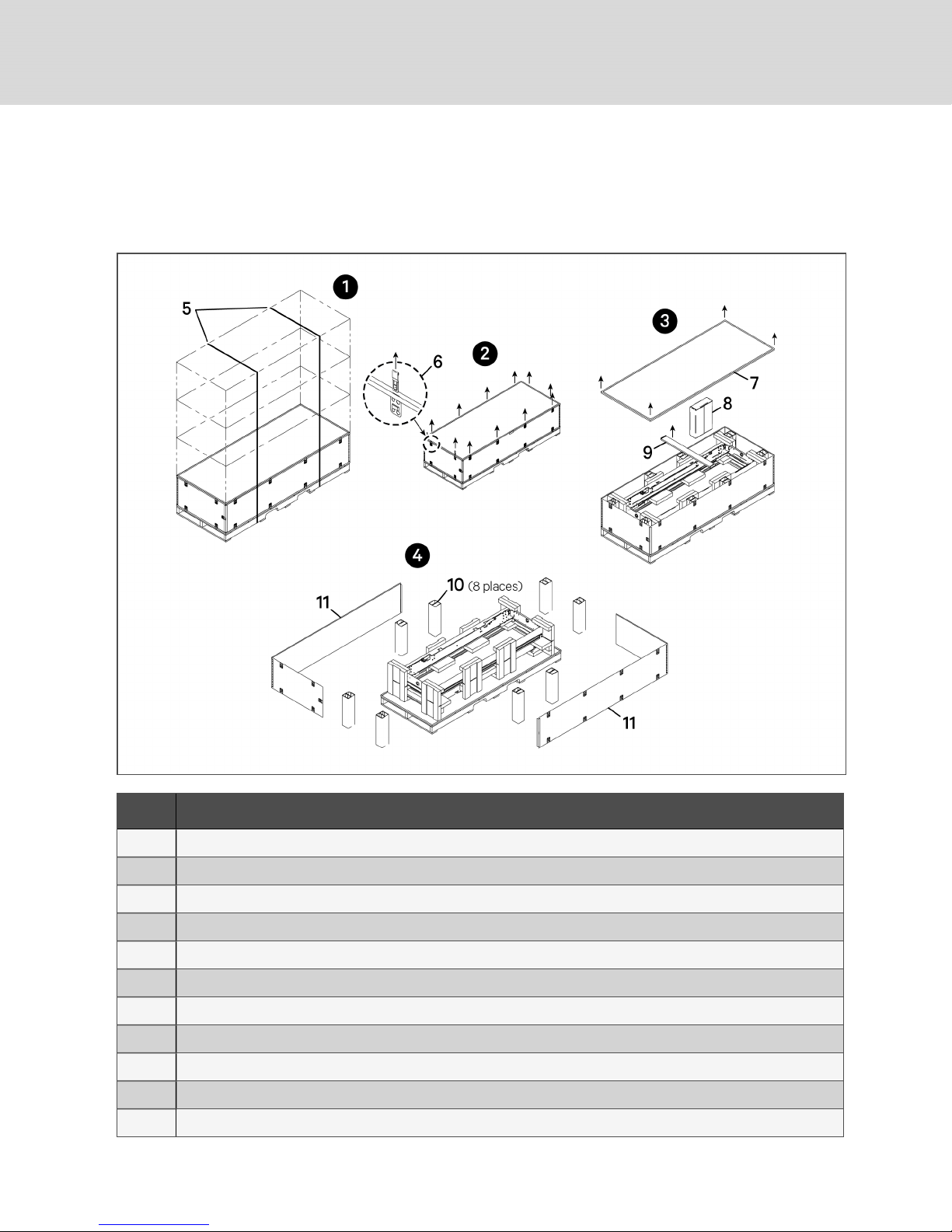
3. Remove the top cover and cross brace from the package, then remove and set aside the
hardware and key package.
4. Remove the remaining spring clips, side panels and any spacers from the package.
Figure 5.1 Removing packaging
Item Description
1 Cut and remove shipping bands if necessary, andlayeach module on the floor for unpacking.
2 Remove the top row of springclips from the packaging.
3 Remove the cover and cross brace, then remove the hardware/key kit package and set aside.
4 Remove the remainingspring clips, side panels, andanyspacers.
5 Shipping bands
6 Top spring clip
7 Top cover
8 Hardware/key kit
9 Cross brace
10 Spacer (8 places)
11 Side panel
26
Vertiv | Liebert® D CD™Installer/User G uide
Page 27

5. Lay two pieces of protective material, each longer and wider than the module frame, on the
floor.
6. Remove foam packaging from both sides of the unit.
7. Using two people, lift the module frame off the pallet and lay it on one piece of protective
material.
8. Compare the serial tag information on the module to the bill of lading. If the information does
not match the product specified, contact your Vertiv sales representative.
9. Using two people, lift the module and lay it on the second piece of protective material with the
door handle facing up.
5 Equipment Inspection and Handling
27
Page 28

This page intentionally left blank
28
Vertiv | Liebert® D CD™Installer/User G uide
Page 29

6 INSTALLATION
These instructions apply only to installing the Liebert® DCD™ on a DCM™ rack by Knurr®. For racks built
by other makers, refer to the instruction sheet shipped with the adapter kit to install the adapter and
DCD™ frame. The rack-adapter kit is described in the drawing DPN004114 included in the Submittal
Drawings on page83.
WARNING! Risk of top-heavy unit falling over. Improper handling can cause equipment
damage, injury or death. Read all of the following instructions and verify that all lifting and
moving equipment is rated for the weight of the unit before attempting to move, lift, remove
packaging from or prepare the unit for installation. Unit weights are specified in Table 4.2 on
page19.
NOTICE
Risk of improper installation and commissioning. Can cause equipment damage.
Installation and commissioning of the unit must be performed only by properly trained and
qualified personnel. All actions must be in accordance with regulations and the manufacturer’s
instructions.
NOTICE
Risk of improper assembly. Can cause unit to malfunction.
The unit must be properly aligned and plumb with the rack to for the unit to function properly
and without water leaks. Use a carpenter’s level to make sure this requirement is met when
commencing the installation.
The hot and cold air within the cabinet must be separated.
NOTICE
Risk of airflow obstructions. Can cause improper air circulation.
To ensure sufficient air circulation make sure there are no obstructions (for example:
packaging materials, tools etc.) left in the unit or cabinet. In particular, check the DCD™’s grids,
heat exchanger, air intake, and the air outlet.
6.1 DCD Frame Preparation
The DCD™ mounts on the rear of the rack.
• Before attaching the frame: remove the rear door from the rack. Refer to the rack’s installation
manual for details.
NOTE: If installing the DCD™ on any type of rack other than the DCM, an adapter kit is necessary.
Follow the installation instructions included with the rack adapter kit for the specific rack. Once the
adapter kit and frame are installed, continue the installation, following the steps in Installing the DCD
Door on page34.
6 Installation
29
Page 30

6.2 Installing the DCD Frame on a DCM Rack
6.2.1 Required Tools
• Phillips screwdriver, PH3
• Adhesive-backed foam (factory-supplied)
• Utility knife
• 8 mm socket and driver
• Scratch awl
• Marker
• Adjustable wrench with a maximum adjustment size of 2 inches (51 mm)
• Torque wrenches, 1-1/2 in. (38 mm) and 1-7/16 (36 mm)
Table 6.1 Required factory-supplied parts
Part Name Vertiv Part # Quantity
Spring Nuts 000782699 16
Diamond Nuts 000770869 7
Self-Adhesive Foam 309894P3 1
Bolts N/A N/A
Condensate Drain Kit N/A N/A
1. After removing the packaging, lift the DCD™ from the pallet or from the protective material.
2. Align the frame of the DCD™ with the rear of the equipment rack.
• Bottom Chilled Water Connections: ensure that the chilled-water connections are
pointing down (see Figure 2.1 on page10).
• Top Chilled Water Connections: ensure that the chilled-water connections are pointing
up.
3. Use a marker or scratch awl to mark the positions for the 17 bolts that will attach the frame to
the DCM. Bolts will be inserted in:
• Five frame holes on the aluminum frame member on the door handle side of the rack.
• Three spring nuts near the top of the hinge side of the rack
• Three spring nuts near the bottom of the rack
• Three diamond nuts in the face of the rack’s top frame member
• Three diamond nuts in the face of the rack’s bottom frame member
4. Lay the DCD™ frame on the protective material.
5. Insert the spring nuts into the groove of the vertical aluminum profile.
6. Move spring nuts to the marked positions using a scratch awl or similar tool.
30
Vertiv | Liebert® D CD™Installer/User G uide
Page 31

7. Install the condensate drain assembly (refer to Figure 6.1 below).
a. Get the condensate drain parts from the parts bag.
b. Press the condensate-hose adapter into the top half of the drain assembly until it snaps
into place. The top of the condensate-hose adapter will extend above the top half of the
drain assembly.
c. Put the O-ring seal on the insert.
d. Insert the assembly in the top of the condensate drain hole.
e. Screw the nut onto the top half of the assembly, tightening it firmly by hand.
Figure 6.1 Condensate drain assembly
Item Description
1 Condensate-hose adapter
2 Bottom nut
3 O-ring
4 Tophalfof assembly
5 The condensate-hose adapter extends above the top half of the assembly.
6 The o-ring fits against the bottom of the DCD.
6 Installation
31
Page 32

8. Connect the condensate-hose Adapter to the condensate tray.
9. Lift the DCD™ frame and align it with the server rack again.
Figure 6.2 Align the DCD frame with the rack
32
Vertiv | Liebert® D CD™Installer/User G uide
Page 33

10. Insert and partly tighten bolts to hold it in place.
NOTE: Performing this step may be easier if a board or similar object is placed under the DCD™ frame to
hold it in place.
11. Insert and lightly tighten the bolts, working all around the perimeter to prevent the frame from
twisting and to ensure the parts fit properly (see Figure 6.3 below).
12. Torque the screws all around the perimeter to 2 ft-lb (3 Nm).
13. Verify that the frame is not twisting.
Figure 6.3 Tighten screws on frame
6 Installation
33
Page 34

14. Thread the brass swivel fitting to the frame by hand to ensure the threads mate properly.
15. Hold the brass body so that it does not rotate and use a torque wrench to tighten to 64 ft-lb
(85 Nm).
Figure 6.4 Brass swivel fitting threaded onto Liebert DCD pipe
Item Description
1 Tighten with a torque wrench
2 Hold stationary (brass body)
6.3 Installing the DCD Door
Required Tools
• Socket hexagonal screw driver - (Allen) 8 mm for M5 screws (5/16")
• Torque wrench
• Phillips screw driver PH3
• Utility knife
WARNING! Risk of heavy module falling. Can cause equipment damage, injury and death. Two
properly-trained and qualified people are required to move and install the module. The DCD™
weighs in excess of 210lb(95kg). Do not leave a DCD™ standing unattended on its side or its
end without adequate support to prevent it from falling over. The module must be supported at
all times or laid flat on protective material until it is installed. Read all instructions before
attempting to move, lift, remove packaging from, or prepare the module for installation. See
Table 4.2 on page19, for unit weights based on model.
1. Attach the three door hinges to the DCD™ door with the supplied screws.
2. Turn the DCD™ face down (handle side down) and lay it on the protective material.
34
Vertiv | Liebert® D CD™Installer/User G uide
Page 35

3. Vent the low-pressure holding charge in the DCD™ by removing the cap on the Schrader valve
and depressing the valve pin.
4. Replace and secure the cap on the Schrader valve.
Figure 6.5 Schrader valve at the top of the door
6 Installation
35
Page 36

5. Loosen the coil plug. This requires two adjustable wrenches in the wrench arrangement shown
in Figure 6.6 below.
One wrench holds the Coil Inlet Fitting stationary and the other turns the plug to remove it.
NOTICE
Risk of improper coil plug removal. Can cause damage to the coil.
It imperative that the coil inlet fitting held stationary and the coil plug is is turned. Turning the
coil inlet fitting can damage the coil.
Figure 6.6 Loosen the coil plug
Item Description
1 Coil inlet plug
2 Coil inlet fitting. Hold fitting stationary while removing plug.
3 Wrench removes plug.
4 Wrench holds fitting stationary.
36
Vertiv | Liebert® D CD™Installer/User G uide
Page 37

6. Remove any debris and wipe the threaded surfaces clean.
7. Align the door to the frame (see Figure 6.7 below).
8. Set the door in the frame—Angle the bottom of the door toward the frame and insert the door
(see Figure 6.7 below).
NOTE: Performing this step may be easier if a board or similar object is placed under the DCD™ frame to
hold it in place.
Figure 6.7 Frame and door alignment
6 Installation
37
Page 38

9. Fasten the door hinges to the frame, starting with the top hinge and finishing with the bottom
hinge (see Figure 6.8 below).
NOTE: Tilting the door may ease installing the hinge bolts.
Figure 6.8 DCD door hinge location
Item Description
1 Hinges, 4 screws in each hinge.
2 Tilt the door to make installingbolts easier.
10. Check that the door moves freely.
If there are any irregularities or roughness in the movement of the door:
• Check for obstructions or loosen screws of the hinges and adjust alignment.
• Tighten any loose screws.
11. Apply pipe wrap or plumber’s dope to the coil connection.
12. Thread one of the short, flexible pipes onto the coil connection by hand to ensure that the
threads properly mate (see Figure 6.9 on the facing page).
13. Tighten to 350 in-lb (39.5 Nm).
NOTICE
Risk of improper tightening. Can cause equipment damage.
Turn only the nut on the flexible pipe when tightening this connection. Moving the coil
connection may damage the coil.
38
Vertiv | Liebert® D CD™Installer/User G uide
Page 39

14. Pull the flexible piping slightly to elongate it enough to connect the union nuts.
NOTICE
Risk of overextending the flexible pipe. Can cause equipment damage.
Pull the flexible piping slightly to elongate it. This makes the piping long enough to connect
the union nuts. Only a slight elongation is necessary. Pulling too hard will overextend the pipe,
making it hard to fit and possibly causing leaks.
15. Insert the sealing ring in the door’s lower piping (see Figure 6.9 below).
Figure 6.9 Aligning pipes and Inserting the sealing ring
6 Installation
Item Description
1 Flexible pipe threaded onto coil connection.
2 Flexible pipe connected to union nuts.
3 Upper pipe connection.
4 Insert sealing ringinto lower pipe connection.
5 Sealing ring
6 Pullslightly on the flexible pipe to elongate it, but do not over-extend the pipe.
39
Page 40

16. With the door fully open, use a torque wrench tighten the union nuts to 64 ft-lb (85 Nm). If a
torque wrench is not available, use two wrenches to reduce the stress on the pipes (see Figure
6.10 below).
• Open-end wrench 1-5/8-in.(41-mm) or an adjustable wrench with maximum size of 2-in.
(51-mm)
• Open-end wrench 1-7/16-in.(36-mm) or an adjustable wrench with maximum size of 2-in.
(51-mm)
17. Check to make sure the door swings freely.
Figure 6.10 Tightening piping
6.4 Installing the DCD Swivel-joint Covers
Tool Required
• Socket hexagonal screw driver - 5/16" Allen (8 mm) for M5 screws
The swivel-joint covers can be identified by the number of identification holes on each cover.
NOTE: The DCD™ is set up for left-side hinges. You can flip the door for right-side hinges.
40
Vertiv | Liebert® D CD™Installer/User G uide
Page 41

Figure 6.11 Swivel-joint cover identification and location bottom connections
Item Description
1 Swivel-joint cover 1
2 Swivel-joint cover 2
3 Swivel-joint cover 3
4 Swivel-joint cover 4
5 Identification holes
6 Left-side hinges
7 Right-side hinges
6 Installation
41
Page 42

To install the covers:
1. Open the DCD™ door. The door must be open to install the covers.
2. Install the outer, then inner swivel-joint covers on the door (see Figure 6.12 below)
Figure 6.12 Swivel-joint cover locations
Item Description
1 Inside cover location
2 Outside cover locations
3 Joint cover
4 Upper cover
5 Lower cover
42
Vertiv | Liebert® D CD™Installer/User G uide
Page 43

3. Fasten screws using the hexagonal screwdriver or socket wrench.
4. Connect the earth (ground) wire of the door to the frame of the Liebert DCD (see Figure 6.13
below).
Figure 6.13 Securing ground wire
Item Descr iption
1 Ground wire connected to bottom corner of DCD
5. Use a “diode” or multimeter to determine that the connection is properly grounded.
6. Check the function of the door lock. The DCD is equipped with a half-inch cylinder lock and
keys.
6 Installation
43
Page 44

6.5 Reversing the Door Handle
If you are modifying a bottom-connection DCD™ to top connections, the handle can be reversed so that it
will not be upside down.
To reverse the handle:
1. Open the door and remove all the bolts holding the door-handle and lock assembly, including
the four brackets. Studs and nuts secure the brackets to the door frame.
2. Flip the door-handle and lock assembly 180 degrees and reattach it with the bolts and nuts.
3. Check the handle and lock to ensure they operate properly.
Figure 6.14 Reverse door handle
Item Description
1 Bolt that secures door-lock assembly, 4 total:2 above the lock and 2 below.
2 Door lock, secured with 3 bolts.
6.6 Installing the Active Fan Module
These instructions apply only to installing DCD Active fan module on a Liebert® DCD™. All materials
required for installation come with the module.
Power-supply Connection Requirements
Standard DCDActive fan modules include a single, wide-range voltage-input port (110/230V). An optional
A/B power-supply transfer switch (110V or 230V) is available to provide back-up if one or the other
supply fails.
44
Vertiv | Liebert® D CD™Installer/User G uide
Page 45

NOTICE
WARNING! Arc flash and electric shock hazard. Open all local and remote electric power
disconnect switches, verify with a voltmeter that power is Off and wear personal protective
equipment (PPE) per NFPA 70E before working with the module. Failure to comply can cause
serious injury or death. Follow all local codes.
WARNING! Risk of contact with high-speed, rotating fan impeller blades. Can cause injury or
death. Open all local and remote electric power-supply disconnect switches, verify with a
voltmeter that power is off, and verify that all fan impellers have stopped rotating before
working in the unit cabinet.
Risk of improper power-supply connection. Can cause equipment damage and loss of warranty
coverage.
Prior to connecting any equipment to a main or alternate power source (for example: back-up
generator systems) for start-up, commissioning, testing, or normal operation, ensure that these
sources are correctly adjusted to the nameplate voltage and frequency of all equipment to be
connected. In general, power-source voltages should be stabilized and regulated to within
±10% of the load nameplate nominal voltage. Also, ensure that no three-phase sources are
single-phased at any time.
6.6.1 Mounting the Active Fan Module on DCD
1. Remove the module cover by lifting up then out, see Figure 6.15 on the next page.
2. Disconnect the Protective-earthing (PE) ground wire from the cover, see Figure 6.15 on the
next page.
6 Installation
45
Page 46

Figure 6.15 Removing cover and disconnecting PE wire
Item Description
1 Key-hole mounting locations.
2 PE connector locations
46
Vertiv | Liebert® D CD™Installer/User G uide
Page 47

3. On the fan module, locate and loosen the screws, but do not remove the screws, see Figure 6.16
below. Then, pull the lower mount downward until it stops.
4. Hang the upper mount of the module on the DCD, then secure the module but pushing the
lower mount upward and tightening the screws.
Figure 6.16 Upper and Lower mounts on the fan module
Item Des cription
1 DCD35 Active fan module
2 DCD50 Active fan module
6.6.2 Connecting Supply Power and Sensors
NOTE: Before connecting the power supply, verify the supply and wiring per local electrical codes.
1. On the top of the module, route the wires/pressure hose through the wiring bridges to the
connectors, see Figure 6.17 on the next page.
2. For modules with the optional TFT, route the temperature-sensor wires from inside the cabinet
through the wire bridges and connect to the RJ-45 port, see Figure 6.17 on the next page.
6 Installation
47
Page 48

The module begins operating immediately and begins controlling the pressure differential in a short time
on both standard and TFT models. The green "operating" LEDis lit on standard models during normal
operation. On TFT models, the display shows the main screen after a brief start-up screen. If you have a
TFT module, see Using the DCD Active TFT Display on page61, to adjust setpoints and configure sensors.
Figure 6.17 Connectors on the Active fan module
Item Description
1 DCD35 Active fan module, top view
2 DCD50 Active fan module, top view
3 Wire bridge
4 IP-interface bushing
5 RJ-45 connector
6 Pressure-hose connector
7 Power-supply A connectors
8 Power-supplyB connec tors
48
Vertiv | Liebert® D CD™Installer/User G uide
Page 49

7 PIPING CONSIDERATIONS AND CONNECTIONS
Refer to site-specific drawings for general locations of the piping connections. The drawings should
specify where the piping connects to the DCD™.
NOTICE
Risk of coil and piping rupture. Can cause equipment damage and major fluid leaks resulting in
serious building damage, expensive repair costs and costly system down time.
Thermal expansion of the cooling fluid without means of expansion can cause the coil and
piping to rupture, spilling cooling fluid in the conditioned space. This can be caused, among
other ways, by closing the ball valves on both the supply and the return pipes. Always allow for
thermal expansion either by leaving at least one of the valves open or by opening the DCD
bleed valve (see Figure 7.8 on page56).
7.1 System Connection Configuration
If possible, when using a chilled-water-distribution unit such as the Liebert® DCP™, connect the DCD™ in
an interlaced configuration (see Figure 7.1 below). In an interlaced configuration, half the cooling
modules in an aisle are connected to one chilled-water-distribution unit and the other half are connected
to another chilled-water-distribution unit. Interlacing the connection piping will keep half the DCD™ units
operating and maintain cooling in the conditioned space should one unit fail.
Figure 7.1 Typical DCD interlaced piping
When using a chilled-water-distribution unit such as the Liebert® DCP, you may employ a ring design (see
Figure 7.2 below) or Tichelmann ring (see Figure 7.3 below) design. In these designs, the pressure drop
for each of the units is approximately the same, which results in even cooling performance.
7 PipingConsiderations and Connections
49
Page 50

Figure 7.2 Ring piping
Figure 7.3 Tichelmann ring piping
50
Vertiv | Liebert® D CD™Installer/User G uide
Page 51

However, if a ring configuration is not possible, connect the DCD™ units in a non-interlaced configuration
as shown in Figure 7.4 below.
Figure 7.4 Typical DCD non-interlaced piping
7.1.1 Using Chilled-water Distribution Units
Using a chilled-water-distribution unit provides these benefits:
• Isolates of the building’s chilled-water circuit from the chilled-water circuit within the data
center. The Liebert® DCP™ circulates the chilled water to DCD while preventing condensation
by maintaining the water temperature above the room dew point.
• Ensures that the proper flow rate to the DCD, a critical factor in achieving and maintaining the
needed capacity.
• Separating the data center from the building chilled-water circuit also minimizes the impact of
a leak within the data center. If a leak occurs, the volume of water is limited to the amount
within secondary piping system instead of the entire building chilled-water system.
7.1.2 Using Open-loop Chilled-water Systems
Maintaining the proper chilled-water flow rate is critical in achieving the design capacity of the DCD. If you
are not using a chilled-water-distribution unit, you must take steps to ensure the proper flow at the unit is
maintained. You should incorporate an expansion tank or another method into the design to account for
fluid expansion.
7.2 Connection Methods and Points
Refer to site-specific drawings for general locations of the piping connections. For connection locations,
refer also to Figure 7.5 on the next page, and 7.3 on the next page.
The assembly and connection means used for piping the DCD system are the same as those used in
conventional chilled-water systems. Observe all standard practices during installation and start-up to
prevent damage and contamination. All piping must be ASTM Type L copper.
The DCD supply- and return-piping connections are described in the Submittal Drawings on page83.
7 PipingConsiderations and Connections
51
Page 52

7.3 Floor Cut-out Dimensions for Units with Bottom Connections
Figure 7.5 Floor cut-out dimensions
7.4 Insulate Piping
Insulate all piping for the DCD to minimize the possibility of condensation.
7.5 Recommended Pipe Sizes
Elbows and restrictions should be minimized to establish sufficient fluid flow.
Table 7.1 Recommended pipe sizes
Piping Run Nominal Pipe Size, in.
2-5/8
Supply or Return Mains
Supply or Return Branches >10 ft 1-3/8
Supply or Return Branches <10 ft 1-1/8
NOTE: When using the DCD with a Liebert® DCP,
refer to the pipe sizes in the Liebert® DCP™ Installer/User Guide.
52
Vertiv | Liebert® D CD™Installer/User G uide
Page 53

7.6 Chilled-water Connection Components
NOTICE
Risk of improper storage. Can cause frozen or damaged coil and piping, resulting in fluid leaks,
equipment damage and serious building damage.
The heat exchanger and the piping must be cleared of any water before the unit is stored.
Compressed air can be used to remove the water. Remove all the vents and the screws before
storing. We recommend storing of the module indoors protected from freezing, dampness, and
contact damage.
NOTE: Chilled-water connections are 1-in. Female BPT. A BPT to NPT adapter is required for
installation in the United States.
Figure 7.6 Chilled water connections
Item Description
1 Chilled-water outlet
2 Chilled-water inlet
3 Condensate drain
7.6.1 Strainer
Install a 20-40 mesh strainer on the chilled-water supply to the Liebert® DCP. The strainer is required to
prevent particles in the chilled water from entering the DCP’s heat exchanger. The strainer must be no
more than 10ft (3m) from the DCP.
7.6.2 Service Valves
Install 1-in. ball valves (field-supplied/field-installed) on the supply and return lines to the DCD to allow
service on the unit without shutting down the entire system.
7.6.3 Balancing Valves
Install balancing valves (circuit setters) in the supply line to the unit. Refer to Capacity Performance for
DCD35 Models on page74, and Capacity Performance for DCD50 Models on page78, for the proper flow
rate required to achieve the site-specific capacity
7 PipingConsiderations and Connections
53
Page 54

7.6.4 Flexible Pipes
DCD™ Flex Pipe kits are available in 59-ft(1500-mm) nominal lengths. The kit consists of two hoses,
manual commissioning valve, and shut off valve. The connections are described in DPN004233 included
in the Submittal Drawings on page83.
Figure 7.7 Acceptable and Unacceptable pipe-bend radius
Item Description
1 Acceptable radii
2 Unacceptable radii
54
Vertiv | Liebert® D CD™Installer/User G uide
Page 55

7.7 Leak Checking
NOTICE
Risk of leaking water. Can cause equipment damage and serious building damage.
Check the chilled water system for leaks before commissioning. Check the chilled water pipe
connection to the heat exchanger regularly. Tighten this connection if necessary.
When setting up the heat exchanger for the first time, inspect the mechanical condition of the
chilled water supply and connection thoroughly.
• Confirm that the flow directions of field-installed components are correct.
• Confirm that all isolating valves are open.
• Test the water quality when filling the system, see Water Quality Requirements on page21.
• Set the pressure at 145 psig (10 bars) maximum for at least 30 minutes or according to local
codes.
• Repair any leaks.
7.8 Filling the Unit
If using a chilled-water-distribution unit, such as the Liebert® DCP™, refer to its user manual for
instructions on filling the DCD and starting the system.
7 PipingConsiderations and Connections
55
Page 56

7.8.1 Bleeding Air from the DCD
The DCD has two Schrader valves, one at the top and one at the bottom. The two valves provide flexibility
for bottom or top chilled-water connections. Air trapped in the unit or piping must be bled from the valve
at the top. Opening the lower valve releases water.
NOTICE
Risk of water release. Can cause equipment and building damage.
The Schrader valve at the top of the DCD must be used when bleeding air from the unit.
Opening the lower Schrader valve will release water.
1. Find the Schrader valve at the top of the DCD, see Figure 7.8 below.
2. Depress the pin to open the valve.
3. Keep the Schrader valve open until the water coming out has no bubbles.
NOTE: When using a top connection, the commissioning valve in the hose kit is an additional bleed
point. Use a bleeding apparatus to prevent water from spilling (available as a ship-loose item).
Figure 7.8 Schrader valve to bleed air from unit
56
Vertiv | Liebert® D CD™Installer/User G uide
Page 57

8 INSTALLATION CHECKLIST
ANDSYSTEMFILLFORSTART-UP
Checks to be Performed
Check device for damage upon receipt
Install and alignto server cabinet
Flexible hoses connected (optional)
properly
Packaging removed from the Liebert
DCD
Allassemblytools removed
Bushings installed properly
Chilled water connections leak-proof /
pressure-tested
Air bled from coil
Chilled water flow adjusted to proper
flow rate
Condensate line connected (if
applicable) androuted to a suitable drain
Unused server space is blocked with
blanking panels
Done (to be signed upon
completion)
Remarks
Top and bottom of server cabinet are
blocked and any cable entries are sealed
to minimize air leakage.
Location Date Installer Signature
8 InstallationChecklistandSystemFillforStart-up
57
Page 58

Customer Site Name
Customer Site Address
Site Contact
Phone Number
Installer Name
Installer Address
Ambient Room
Temperature
Room Humidity at Site
of Commissioning
°F (°C)
% Relative Humidity
Liebert DCD Serial#
Comments
Check ofalignment Yes No
Shipping damage Yes No
If yes, has the shipper been notified Yes No
Residualpackagingremoved Yes No
Assemblytools removed Yes No
58
Vertiv | Liebert® D CD™Installer/User G uide
Page 59

Building chilled water system
Chilled Water
Liebert DCD
Connected to Building Chilled Water? Liebert DCP™
Chilled Water Temperature
(primary)
Chilled Water Pressure
Connection
With Glycol Glycol Type
Without Glycol
Supply °C °F
Return °C °F
Supply bar Supply psi
Return bar Return psi
Liebert DCD Flexible Hose
ExternalFlow Regulator
ExternalIsolation Valves
Mechanical Functions
Damage to Heat Exchanger/
Connections/ Fins/Tubes/Surface
Remarks
None Existing
Thermodynamic Checks
Pipe Duct Inlets/Cable Sealed Yes No
Remarks
Condensed Drain Connected Yes No
Remarks:
Thermodynamic Checks
Condensate on Coil Surface Yes No
Remarks
Chilled Water Entering Heat Exchanger °F °C
Chilled water leaving heat exchanger °F °C
Cabinet Temperature inFront of Heat Exchanger °F °C
Cabinet Temperature Behind of Heat Exchanger °F °C
Chilled Water System Bled Yes No
8 InstallationChecklistandSystemFillforStart-up
59
Page 60

Chilled Water System Pressure Tested Yes No
Proper Chilled Water Flow Rate Set to Liebert DCD Yes No
Volume Flow
GPM External
l/m External
Correctness of values above is hereby affirmed
Start-up Performed By Date Signature
Customer Date Signature
60
Vertiv | Liebert® D CD™Installer/User G uide
Page 61

9 USING THE DCD ACTIVE TFT DISPLAY
If the TFT model of the DCD Active fan module is installed on your DCD unit, the touch-screen provides
real-time operating status details and lets you adjust and configure operational settings.
NOTE: The Standard model DCD Active offers no operating adjustments. When supplied with power,
the Standard DCD Active automatically monitors differential pressure and adjusts fan speed to
maintain a 0-Pa pressure differential.
9.1 Main Screen
When the DCD Active is powered, the TFT touch-screen displays the main screen, which provides a highlevel status summary. Touch an area of the screen to display details of the summarized data.
Touch on any screen to return to the previous screen.
Figure 9.1 Main screen
Item Descript ion
Fan-operation summary. Current fan-speed percentage and color-coded operating status. See Viewing Fan Status Detailon
1
the next page.
Cabinet sensors summary. Average of temperature readingsfrom all sensors on the hot side. See Viewing Cabinet
2
Temperature-sensor Status on page64.
3 Opens the settings menu. See Settings Menu on page65
Exhaust-air sensors summary. Average of temperature readings from all sensors on the cold side. See Viewing Exhaust-air
4
Sensor Status on page63.
9 Usingthe DCD Active TFT Display
61
Page 62

9.1.1 Viewing Fan Status Detail
Touch the fan-summary area on the main screen to view the fan details.
Figure 9.2 Fan Detail
Item Description
1 Current fan-speed operating percentage. All fans operate at the same speed.
Color-coded icon represents the operating status of each fan:
2
Also lists the current rotations-per-minute (rpm) for each fan.
• Green = OK
• Red = Disturbance
62
Vertiv | Liebert® D CD™Installer/User G uide
Page 63

9.1.2 Viewing Exhaust-air Sensor Status
Touch the exhaust-air-sensor summary area on the main screen to view the temperature-sensor details.
Figure 9.3 Exhaust Air Sensors detail
Item Description
1 Average of allexhaust-air (cold side) temperature-sensor readings.
2 Current reading of each temperature sensor.
9 Usingthe DCD Active TFT Display
63
Page 64

9.1.3 Viewing Cabinet Temperature-sensor Status
Touch the cabinet-sensor summary area on the main screen to view the temperature-sensor details.
Figure 9.4 Cabinet Sensors detail
Item Description
1 Average of allcabinet (hot side) temperature-sensor readings.
2 Current reading of each temperature sensor.
64
Vertiv | Liebert® D CD™Installer/User G uide
Page 65

9.2 Settings Menu
The settings menu offers unit and system information and lets you configure operating parameters.
Touch an icon to open the screen or sub-menu.
Figure 9.5 Settings menu
Item Descript ion
1 Info displays read-onlysystem information.
2 Messages displays read-onlysystem messages.
3 Opens the Temperature Sensors menu, see Temperature Sensors Menu on the next page
Opens the Regulation screen, which adjusts the differential-pressure setpoint, see Differential-pressure Regulation on the
4
next page.
5 Opens the Set-up menu, see Set-up Menu on page67.
9 Usingthe DCD Active TFT Display
65
Page 66

9.2.1 Temperature Sensors Menu
The temperature-sensors menu lets you choose the units used for readings, and it lets you "teach" the
DCD Active up to 4 cabinet temperature sensors to monitor and average, see Teaching Sensors to the
DCD Active on the facing page.
NOTE: Exhaust-air temperature sensors in the DCD Active can also be "taught," but are accessed via
the set-up menu. The teaching procedure is identical.
Figure 9.6 Temperature Sensors menu
Item Description
1 Opens the Choose Units screen, see Choosing Temperature Units below.
2 Opens the Teach Cabinets Sensors screen, Teaching Sensors to the DCD Active on the facing page.
Choosing Temperature Units
To choose Celsius or Fahrenheit for the temperatures readings, open the Choose Units screen, and touch
to check the box of the temperature unit to use.
9.2.2 Differential-pressure Regulation
Regulation lets you choose the way DCD Active manages the differential pressure by selecting a
differential-pressure setpoint.
Touch the –/+ buttons to select one of the following pressure setpoints:
• Slight excess pressure
• Neutral
• Slight under pressure
66
Vertiv | Liebert® D CD™Installer/User G uide
Page 67

9.2.3 Set-up Menu
The password-protected set-up menu lets you set the pressure level maintained by the selection for
differential-pressure setpoint, see Differential-pressure Regulation on the previous page, and it lets you
"teach" the DCD Active up to 4 exhaust-air temperature sensors to monitor and average, see Teaching
Sensors to the DCD Active below.
Default password = 94424
Figure 9.7 Set-up menu
Item Description
1 Opens Pressure Levels screen, see Setting Levels for the DifferentialPressure Setpoint below.
2 Opens Teach Exhaust Air Sensors screen, see Teaching Sensors to the DCD Active below.
Setting Levels for the Differential Pressure Setpoint
Touch the –/+ buttons to select the pressure (Pa) that DCD Active maintains for the differential-pressure
setpoint chosen in the Regulation screen, see Differential-pressure Regulation on the previous page:
• Low positive = Slight excess pressure
• Neutral = Neutral
• Low negative = Slight under pressure
Teaching Sensors to the DCD Active
The DCD Active can communicate with up-to 4(optional) temperature sensors in the cabinet and up-to 4
(optional) exhaust-air temperature sensors inside the DCD Active. When taught, each sensor is assigned
a number, 1to4, and DCD Active "learns" or "remembers" that sensor and uses it for averages and status
readings.
Though accessed through separate menus, the teaching procedure is identical.
9 Usingthe DCD Active TFT Display
67
Page 68

NOTE: Only the sensor being configured may be connected during the teaching procedure. Once
taught, the may be disconnected, and will be recognized.
Figure 9.8 Teach-sensor screens
teach_sensor_screens
To teach a sensor to the DCDActive:
1. Disconnect all sensors, except the sensor to configure.
2. For a cabinet sensor, open the teach-sensor screen via the Settings > Temperature Sensors
menu.
– or –
For an exhaust-air sensor, open the teach-sensor screen via the Settings > Set-up menu.
3. Use –/+ to assign a number, 1to4, to the sensor, the touch the magnifying-glass to begin
teaching.
4. Touch OK after confirming that a single sensor is connected.
The DCD Active takes a few seconds to locate the sensor, and the temperature reading from
the sensor displays when the connection is complete.
• To delete a learned sensor, disconnect the sensor, select its number, and complete the
teaching procedure. The number is no longer associated with the sensor.
• To re-assign a number, connect a new/different sensor, select the number, and complete
the teaching procedure. The number is assigned to the connected sensor.
5. Reconnect all the configured sensors, which begin communicating temperature data because
the DCDactive "remembers" them.
68
Vertiv | Liebert® D CD™Installer/User G uide
Page 69

10 MAINTENANCE
CAUTION: Risk of improper repair and maintenance. Can cause reduced unit performance,
equipment damage and injury.
All maintenance and repair jobs must be performed by properly trained and qualified personnel.
All actions must be in accordance with regulations and the manufacturer’s instructions. Use
only Vertiv-approved tools and parts for maintenance and repair.
NOTICE
Risk of dirty heat exchanger. Can cause reduced unit performance (increased pressure drop or
poor heat transfer).
Clean the heat exchanger fins with a vacuum cleaner, soft brush or compressed air.
10.1 General Maintenance
1. Check the heat exchanger for dirt and debris.
2. Check function of the isolation valves.
3. Check the chilled-water system for leaks.
10 Maintenance
69
Page 70

This page intentionally left blank
70
Vertiv | Liebert® D CD™Installer/User G uide
Page 71

APPENDICES
Appendix A: Technical Support and Contacts
A.1 Technical Support/Service in the United States
Vertiv™ Corporation
24x7 dispatch of technicians for all products.
1-800-543-2378
Liebert® Thermal Management Products
1-800-543-2778
Liebert® Channel Products
1-800-222-5877
Liebert® AC and DC Power Products
1-800-543-2378
A.2 Locations
United States
Vertiv Headquarters
1050 Dearborn Drive
Columbus, OH, 43085, USA
Europe
Via Leonardo Da Vinci 8 Zona Industriale Tognana
35028 Piove Di Sacco (PD) Italy
Asia
7/F, Dah Sing Financial Centre
3108 Gloucester Road
Wanchai, Hong Kong
71
Page 72

This page intentionally left blank
72
Vertiv | Liebert® D CD™Installer/User G uide
Page 73

Appendix B: Specifications
Table B.1 Liebert DCD Specifications
Model: 35 50
Housing Material Steel Plate
CoilMaterial Copper Tubes and Aluminum Fins
Ambient Operating
Temperature °F (°C)
Maximum Capacity 35kw 50kw
Maximum Absolute Humidity 8 g/kg
Dimensions, Door Only
Height, in. (mm) 78-3/4 (2000)
Width, in. (mm) 23-5/8 (600) 31.5 (800)
Depth, in. (mm) 6 (151)
Shipping Dimensions
Height, in. (mm) 24" (610)
Width, in. (mm) 36" (914)
Depth, in. (mm) 91 (2311)
Weight, lb (kg)
Unit Only 210 (95.2) 230 (104.3)
Shipping 325 (147.4) 355 (161.0)
Chilled Water Connections
Chilled Water Supply
*Connections at the door are 1" BPT. Connections to field-installed header are 1" NPTwith
50 - 95 (10 - 35)
1” NPT
required BPT/NPT adapter.
Chilled Water Return 1” NPT
Maximum Operating Pressure
bar (psi)
Exterior Finish Black Matte, Heat-Fused Powder Coat
Safety CSA Approved
145 (10)
73
Page 74

Table B.2 Replacement parts
Quantity
Part Name Part #
Replacement Parts
Swivel cover with slotted hole labeled "1" 080142908000001 1
Swivel cover with slotted hole labeled "2" 08042908000001 1
Swivel cover with slotted hole labeled "3" 080142928000001 1
Swivel cover with slotted hole labeled "4" 08014292800002 1
Self-Adhesive Foam 080144909 1
Condensate Hose Adapter 080090620 1
Spring Nuts 000782699 16
Diamond Nuts 000770869 7
Required
per Unit
GroundingWire
B.1 Capacity Performance for DCD35 Models
Figure B.1 DCD35 Performance @ 5.2 m3/h
000797999 1
000798169 1
74
Vertiv | Liebert® D CD™Installer/User G uide
Page 75

Figure B.2 DCD35 Performance @ 22.9 US GPM
Figure B.3 DCD35 Performance @ 3.5 m3/h
75
Page 76

Figure B.4 DCD35 Performance @ 15.4 US GPM
Figure B.5 DCD35 Performance @ 1.8 m3/h
76
Vertiv | Liebert® D CD™Installer/User G uide
Page 77

Figure B.6 DCD35 Performance @ 7.9 US GPM
Figure B.7 DCD35 Air-side pressure drop
77
Page 78

Figure B.8 DCD35 Water-side pressure drop
B.2 Capacity Performance for DCD50 Models
Figure B.9 DCD50 Performance @ 31.7 US GPM
78
Vertiv | Liebert® D CD™Installer/User G uide
Page 79

Figure B.10 DCD50 Performance @ 22.0 US GPM
Figure B.11 DCD50 Performance @ 12.9 US GPM
79
Page 80

Figure B.12 DCD50 Air-side pressure drop (H2O)
Figure B.13 DCD50 Air-side pressure drop (Pa)
80
Vertiv | Liebert® D CD™Installer/User G uide
Page 81

Figure B.14 DCD50 Water-side pressure drop (psi)
Figure B.15 DCD50 Water-side pressure drop (kPa)
81
Page 82

This page intentionally left blank
82
Vertiv | Liebert® D CD™Installer/User G uide
Page 83

Appendix C: Submittal Drawings
The submittal drawings are in the order of document part number (DPN). Table C.1 below, groups the
drawings by topic/application.
Table C.1 Submittal-drawings Contents
Document Number Title
Planning Dimensions
DPN004112 Dimensional Data, DCD35
DPN004113 DimensionalData, DCD50
DPN004114 Rack-adapter kit components
Piping Connections
DPN004233 Supply-/Return-hose kit
83
Page 84

This page intentionally left blank
84
Vertiv | Liebert® D CD™Installer/User G uide
Page 85

LIEBERT DCD
DIMENSIONAL DATA
REAR RACK COOLER DCD35 PASSIVE
19 3/8"
7/8"
24mm
492mm
Rear
Top View
Front
1 3/4"
45mm
1 3/4"
45mm
4 3/4"
120mm
6"
151mm
76 7/8"
1954mm
2 7/8"
73mm
23 5/8"
600mm
12 5/8"
322mm
Front
1 1/8"
O
29mm
Bottom View
Rear
2"
52mm
DPN004112
Page :1 /1
Form No.: DPN001040_REV4
REV : 1
REV DATE : 3/17
Page 86

LIEBERT DCD
FRAME DIMENSIONAL DATA
REAR RACK COOLER DCD50 PASSIVE
29 3/8"
1 3/4"
45mm
745mm
Rear
7/8"
24mm
76 7/8"
1954mm
1 3/4"
45mm
7/8"
23mm
Top View
Front
4 3/4"
120mm
6"
151mm
2 3/4"
71mm
DPN004113
Page :1 /1
Form No.: DPN001040_REV4
31 1/2"
800mm
O
1 1/8"
29mm
16 5/8"
422mm
Front
Bottom View
Rear
2"
52mm
REV : 3
REV DATE : 6/18
Page 87

LIEBERT DCD
CUSTOMER RACK ADAPTER KIT
REAR RACK COOLER
Rack Adapter (Connecting Kit)
(Dimensions vary based on customer rack;
required for 3rd party racks)
Liebert DCD
Front of Customer Rack
DPN004114
Page :1 /1
Form No.: DPN001040_REV4
Customer Rack
(Rear door removed)
REV : 0
REV DATE : 3/17
Page 88

LIEBERT DCD
COMPONENT LOCATION
SUPPLY AND RETURN HOSE KIT BOTTOM PIPING CONNECTIONS
(LEFT HINGE)
1
6
4
3
2
4
INCLUDED IN SHIP LOOSE HOSE KIT
1. DCD Supply Water Connection
2. DCD Return Water Connection
3. Flex Metal Hose (Available in 59"(1500mm))
4. Male to Male Nipple (Loctite 5776 is required to seal adapter [items 4 & 5, and 4 & 6])
5. Manual Valve Assembly (Return Side)
6. Shut Off Valve Assembly (Supply Side)
7
5
ADDITIONAL SHIP LOOSE ITEM
7. BPT to 1" NPT nipple adapter or optional 300mm (12") hose adapter (Connect to field installed supply and return header)
DPN004233
Page :1 /2
Form No.: DPN001040_REV4
REV : 1
REV DATE : 4/18
Page 89

LIEBERT DCD
COMPONENT LOCATION
SUPPLY AND RETURN HOSE KIT TOP PIPING CONNECTIONS (LEFT HINGE)
7
5
6
4
4
1
INCLUDED IN SHIP LOOSE HOSE KIT
1. DCD Supply Water Connection
2. DCD Return Water Connection
3. Flex Metal Hose (Available in 59"(1500mm))
4. Male to Male Nipple (Loctite 5776 is required to seal adapter into [items 4 & 5, and 4 & 6])
5. Manual Valve Assembly (Return Side)
6. Shut Off Valve Assembly (Supply Side)
3
2
ADDITIONAL SHIP LOOSE ITEM
7. BPT to 1" NPT nipple adapter or optional 300mm (12") hose adapter (Connect to field installed supply and return header)
DPN004233
Page :2 /2
Form No.: DPN001040_REV4
REV : 1
REV DATE : 4/18
Page 90

Vertiv | Liebert® D CD™Installer/User G uide
Page 91

VertivCo.com | Vertiv Headquarters, 1050 Dearborn Drive, Columbus, OH, 43085, USA
© 2018 Vertiv Co. Allrights reserved. Vertiv and the Vertiv logo are trademarks or registered trademarks of Vertiv Co. Allother names and logos referred to
are trade names, trademarks or registered trademarks of their respective owners. While every precaution hasbeen taken to ensure accuracy and
completeness herein, Vertiv Co. assumes no responsibility, and disclaims allliability, for damages resulting from use of this information or for anyerrors or
omissions. Specifications are subject to change without notice.
SL-17307_REV6/590-1699-501C
 Loading...