

Page 1

Liebert CRV+
Precision Air Conditioner
User Manual
Page 2

Page 3

Copyright by Vertiv Co. Ltd.
The content in this document is subject to change without notice. All rights, including rights of
translation, reproduced by printing, copying or similar methods, and even of parts, are reserved. Violators
will be liable for damages. All rights, including rights deriving from patent license or registration of a
utility model or design, are reserved. No part of this document may be reproduced or transmitted in any
form or by any means without the prior written consent of Vertiv Co. Ltd.
Notice
The purchased products, services, and features are stipulated by the contract made between Vertiv Co.,
and the customer. All or part of the products, services, and features described in this document may not
be within the purchasing scope or the usage scope. Unless otherwise specified in the contract, all
statements, information, and recommendations in this document are provided "AS IS" without warranties,
guarantees or representations of any kind, either express or implied. The information in this document is
subject to change without notice. Every effort has been made in the preparation of this document to
ensure the accuracy of the contents, but all statements, information, and recommendations in this
document do not constitute a warranty of any kind, express or implied.
Vertiv Co., Ltd.
• China
Website: www.vertivco.com
E-mail: support@Vertivco.com
mer service hotline: 4008876510
Custo
• Asia Pacific
Homepage: www.vertivco.com.
E-mail: overseas.support@Vertivco.com
For Technical Support, users may contact the nearest Vertiv Co. local sales office or service center.
Page 4
Purpose of the Document
Warning/Danger/Caution
potentially harmful situation that can result in death or injury. It
which may result in danger and safety issues thereby having an
The Note section indicates additional and useful information,
help make maximum utilization of the resources at hand. Helpful
information related to the mainstream stuff also comes under
This doc
ument applies to the Liebert CRV+ series of precision air conditioners and cooling solutions
which maintain an optimal environmental control mainly for testing laboratories, data center rooms and
similar technological ecosystems at minimal operating costs. This document explains the product
description, installation measures, operational workflow, maintenance, and detailed aspects from the user
perspective. The figures used in this document are for reference only.
Please read this manual carefully before installing, maintaining, and troubleshooting, especially the
warning information in the manual
Styling used in this Guide
The styles used in the manual will be defined as mentioned in the following table:
Situation Description
Warning/Danger/Caution
The
also indicates instructions that need to be adhered to, failing
adverse effect on the reliability of the device and security. Even
for practices not related to physical injury, the content under
the Warning heading is used for precautions which need to be
taken which, otherwise, could result in equipment damage,
performance degradation, or interruption in service.
note indicates a hazardous or
Note
Version History
Issue
1 V1.0 ---
including tips and tweaks. It also calls attention to best
practices and industry-best protocols that are standardized and
the Note heading helping the users get to grips with the
definitions, concepts, and terminologies used in the manual.
Revision
Changes
Page 5

Safety Precautions & Measures
The important safety precautions and measures that should be followed during the installation and
maintenance of the Liebert CRV+ models are described in the following sections.
Read the manual prior to installation and operation of the unit. Only qualified personnel should move,
install, or service this equipment.
The user reads and takes into account all the precautions, compliance, and safety measures before
working on the equipment. The unit control must be used exclusively for the purpose which it is
intended for; the manufacturer takes no liability for incorrect use or a modification to the unit control.
Adhere to all the Warnings and Cautionary measures included in the manual.
Please read this manual carefully before installing, maintaining and troubleshooting; especially
the Warni
pay attention to the warning labels on the unit and its components.
This manual is retained for the entire service life of the machine. The user must read all the precautions,
danger, warnings, and cautionary measures mentioned in the manual prior to carrying out any operations
on the machine. Each machine is equipped with an electrical insulation, which allows the users to work in
safe conditions. The main switch is positioned on the electrical panel cover; Open the right door to access
it. Before any maintenance operation, switch off the machine with this electronic insulation device in order
to eliminate risks such as electrical shocks, burns, automatic restarting, moving parts, and remote
control. The panel key, supplied along with the unit, must be kept by the personnel responsible for the
maintenance. The protective covers can be removed after the electric power has been cut off by opening
the main switch.
ng/ Danger/ Caution information in the User Guide. Apart from the User Guide, also
In the following section, take a look at the various cautionary measures and warnings that need to be read
carefully prior to installing or operating the system.
Disconnect the local and remote power supplies prior to working with the unit.
Prior to the installation process, read all the instructions, verify if all the parts are in place, and check the
nameplate to ensure that the voltage matches the utility power that is available for that unit.
The controller doesn’t isolate power from the unit even in the Off mode. Moreover, some internal
components require and receive power even during the Off mode.
If the unit door is open while the fans are operating, the airflow may result in abrupt slamming of the door
resulting in injury. Another aspect is the presence of small objects in the fans bay which may result in
object ejection during the fan start-up and there is a probable risk of being hit by these objects leading to
grievous injury as well as causing equipment damage.
Page 6

The CRV+ unit isolation switch is inside the unit. The line side of this switch contains live high voltage.
In order to ensure there is no voltage inside the unit, install and open a remote isolation switch.
The unit contains fluids and gases under high pressure. Therefore, the pressure should be relieved
before working with the piping.
Various components such as compressors, refrigerant discharge lines, and humidifiers are extremely hot
during the unit operation. Therefore, allow sufficient time for the unit to cool down before working with
the unit cabinet. Handle the unit with extreme caution and wear safety equipment such as protective
gloves, safety shoes, and arm protection while working with the hot compressors, discharge lines, and
reheats.
There is a risk of leaking water that can cause damage to the equipment as well as the building. There
should be an effective water drain connection and facilities. Installation should be precise.
Implementation of the application and service practices should be suitable and fault-free. Not complying
with these norms will result in water leakage from the unit. Water leakage can result in massive damage
and loss of critical equipment in the hosting ecosystem. Therefore, care should be taken to ensure that
the unit must not be located directly above any equipment that could sustain damage due to water and
excessive moisture. Using a leak detection system for unit and system supply lines are recommended by
Vertiv Co.
Page 7

TABLE OF CONTENTS
Chapter 1 Introduction ........................................................................................................... 1
1.1 Model Nomenclature .................................................................................................................... 2
1.2 Basic Performance Parameters................................................................................................. 2
1.3 Product Description .................................................................................................................... 3
1.3.1 DC Brushless Compressor................................................................................................................. 4
1.3.2 Fan ....................................................................................................................................................... 5
1.3.3 Evaporator .......................................................................................................................................... 5
1.3.4 Electronic Expansion Valve (EEV) ................................................................................................... 6
1.3.5 Electrode Humidifier ......................................................................................................................... 6
1.3.6 Electric Heater ................................................................................................................................... 7
1.3.7 Sight Glass .......................................................................................................................................... 7
1.3.8 Filter Drier........................................................................................................................................... 7
1.3.9 Micro-Controller ................................................................................................................................ 7
1.3.10 Condenser ......................................................................................................................................... 8
1.4 Optional Equipment .....................................................................................................................8
1.5 Working Conditions .....................................................................................................................9
1.5.1 Operating Environment ..................................................................................................................... 9
1.5.2 Storage Environment ........................................................................................................................ 9
1.5.3 Refrigerant Charging Requirement ............................................................................................... 10
Chapter 2 Installation ........................................................................................................... 12
2.1 Pre-installation ........................................................................................................................... 12
2.1.1 Transportation & Movement........................................................................................................... 12
2.1.2 Unpacking ......................................................................................................................................... 13
2.1.3 Inspection ......................................................................................................................................... 14
2.2 Installation Preparation (Site Preparation) ......................................................................... 14
2.2.1 Equipment Room Requirement ...................................................................................................... 14
2.2.2 Installation Space requirements ................................................................................................... 15
2.2.3 Installation Tools ............................................................................................................................. 16
2.3 Mechanical Installation ............................................................................................................ 17
2.3.1 System arrangement during installation ...................................................................................... 18
2.3.2 System Installation Mode ............................................................................................................... 19
2.3.3 Product Dimensions ........................................................................................................................ 20
2.3.4 Installation Procedures .................................................................................................................. 23
2.3.5 Piping ................................................................................................................................................ 26
2.3.6 Removing Transportation Fastener and Vibration Absorber ................................................... 34
2.3.7 Checklist for completed mechanical installation ........................................................................ 36
Page 8

2.4 Electrical Installation................................................................................................................37
2.4.1 On-site Wire connections ............................................................................................................... 37
2.4.2 Installation Notes ............................................................................................................................ 37
2.4.3 Connecting cables of the Indoor unit ........................................................................................... 38
2.5 Commissioning Overview ....................................................................................................... 43
2.5.1 Self Check ......................................................................................................................................... 43
2.5.2 Preparations for Startup ................................................................................................................ 44
2.5.3 Startup Inspection .......................................................................................................................... 46
Chapter 3 System Operation & General Maintenance .................................... 50
3
.1
System Operation
3.1.1 Micro-Controller ............................................................................................................................... 50
3.1.2 Control buttons ................................................................................................................................ 50
3.1.3 Common Operational function examples ..................................................................................... 51
3.1.4 Main Screen ...................................................................................................................................... 52
3.1.5 Password interface .......................................................................................................................... 53
3.1.6 Menu Structure ................................................................................................................................ 53
3.2 General Maintenance ............................................................................................................... 69
3.2.1 Routine Maintenance & Inspection (Monthly) ............................................................................. 69
3.2.2 Routine Maintenance and Inspection (Half -Yearly) .................................................................. 70
3.2.3 Self-Diagnosing Functions ............................................................................................................. 71
3.2.4 Maintenance of Electrical Control utilities .................................................................................. 71
3.2.5 Air Filter Maintenance .................................................................................................................... 73
3.2.6 Fan Kit Maintenance ....................................................................................................................... 74
3.2.7 Electrical Heater Maintenance ...................................................................................................... 74
3.2.8 Refrigerating System Maintenance .............................................................................................. 74
3.2.9 Drainage system maintenance ...................................................................................................... 74
3.2.10 Troubleshooting ............................................................................................................................ 75
....................................................................................................................
..
50
APPENDIX 1 - Circuit Diagrams ............................................................................................................ 79
APPENDIX 2 - Micro-processing Controller Menu Structure................................................................ 82
APPENDIX 3 - Alarm Control Menu Table ............................................................................................ 84
APPENDIX 4 - Hazardous Substances or Elements Declaration .......................................................... 85
APPENDIX 5 - Troubleshooting of Common Startup Faults ................................................................. 86
Page 9

PART I
GENERAL INFORMATION
Page 10

Page 11
Chapter 1 Introduction
The Liebert CRV+ series is the next generation series of air conditioners that provide precise
environmental control. The Liebert CRV+ models are the latest in the long line of modern enterprisegrade products from the Liebert family. Incorporating the high standards associated with the Liebert
name, the CRV+ series utilizes the latest technology, system components, and streamlined
manufacturing process.
Liebert CRV+ air conditioners are products that are specifically created and designed for the small-andmedium data centers, computer rooms, and similar ecosystems which call for a high degree of accuracy
and precision. It addresses the needs and challenges associated with such applications and setups. It
caters to sensitive applications which need a suitable environment for optimal performance. Therefore,
care should be taken while testing these sensitive products or maintaining a favorable environment for
mission critical equipment, as even a slight deviation may lead to inaccurate results. Precision Air
Conditioning must not only keep room conditions within a specific range but also must have the
precision to react quickly to a drastic change in heat load and prevent wide temperature fluctuations.
The CRV+ air cooled AC unit is packed with features such as high reliability, high sensible heat ratio, and
large airflow. The unit is an air-cooled single cooling system and configured with DC Speed Regulation
back- inclined centrifugal fan.
Packed with a host of features, it lowers the sound emissions significantly and thereby reduces the noise
pollution. It is a top-notch system that adheres to the standard in Precision Air Cooling in terms of
energy-efficiency, space requirements, and reliability.
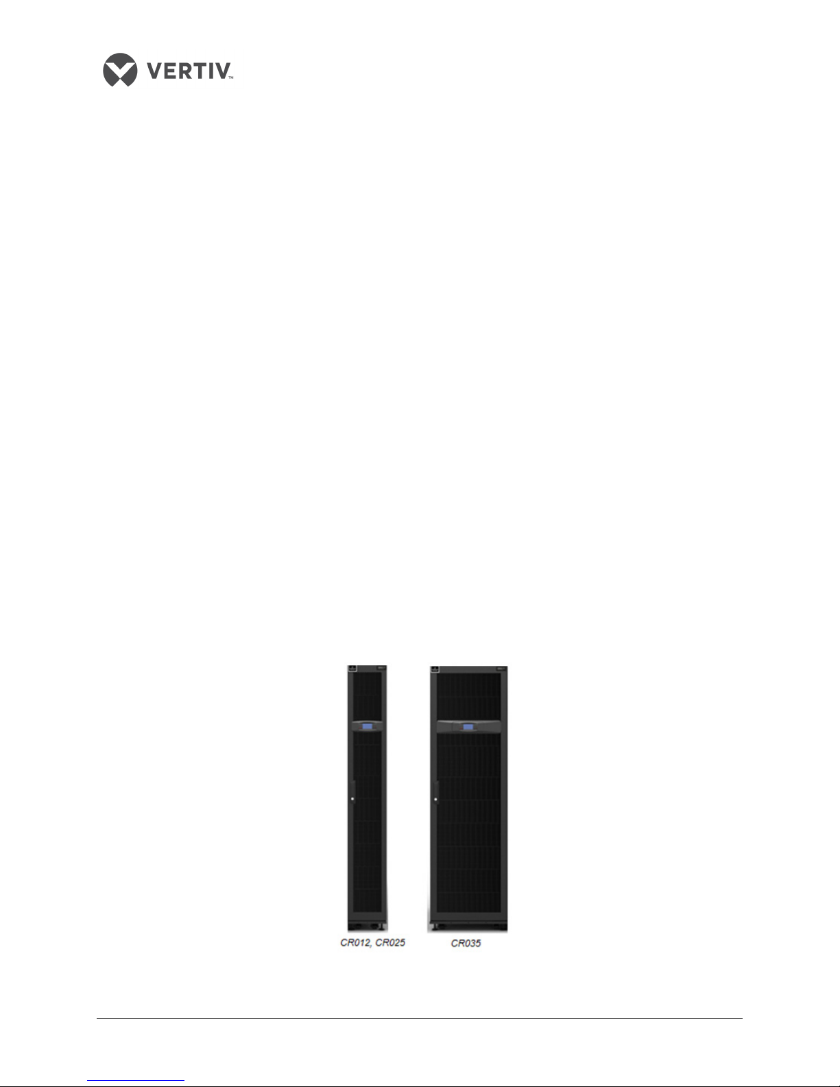
Figure 1-1 shows the appearance of various models in the Liebert CRV+ series:
Vertiv | Liebert CRV+ | User Manual 1
1-1 Models in the CRV+ series
Figure
Page 12
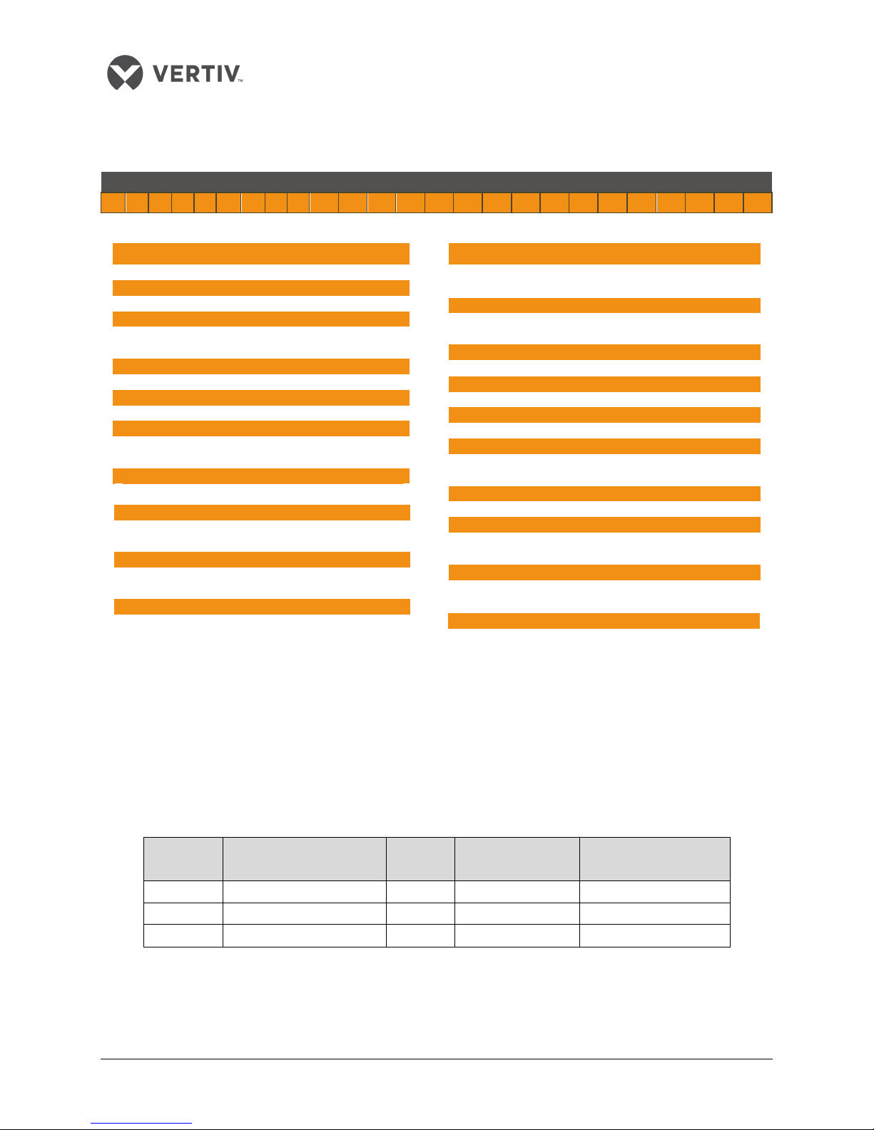
1.1 Model Nomenclature
1 2 3 4 5 6 7 8 9
10
11
12
13
14
15
16
17
18
19
20
21
22
23
24
25
C R 0 2 5 H A 1 3 8 O S 0
2 E 1 0 0 0 0 C V 0 0
0
CR Liebert CRV+
Bit 3 ~ Bit 5 Series Name Description
Bit 6 Air Discharge
R Horizontal supply with guide grill
Horizontal supply without guide grill
Bit 7 System Type
A
Bit 8Airflow
1 EC Fan
Bit 9 Power Supply
3 380-415V/3 ph/50Hz +N
T 380/3 ph/60Hz +N
CR025
20.8
6.1 3 1.5
The model nomenclature of the CRV+ air cooled unit is shown in Figure 1-2:
Bit 1 and Bit 2 Product Model Bit 14 Filter
G4 with filter clogged switch
G4
Standard DX Air Cooled Coiled &
Electronic Expansion Valve (EEV)
With condensate drain pump
None
025 Nominal Capacity
H
Air cooled
Bit 10 System Configuration
8 R-410A brushless scroll compressor
Bit 11 Humidifier
0 None
S Electrode humidifier
Bit 12 Display
L Large Display
S Standard display panel
Bit 13 Heating
0
1
None
Electrical heater
0
2
Bit 15 Coil and value
E
Bit 16 Cabinet Color
1 Standard color ( Z-7021 black-grey)
Bit 17 High Pressure Option
0 None
Bit 18 Low Voltage Locking Option
0 None
Bit 19 Monitor
0 None
S SIC Card
Bit 20 Detector
0 None
Bit 21 Package
P Domestic
C Overseas (sea worthy)
Bit 22 Special Function
A None
V
Bit 23~25 Special Identifier for order
0
Figure 1-2 Model Nomenclature
1.2 Basic Performance Parameters
The basic performance parameters of the Liebert CRV+ AC series are given in Table within Listing 1.1.
Listing 1.1
Model
Nominal cooling
capacity (kW)
CR012 13.6 3.3 2 /
CR035 38.1 10.1 5.5 1.5
Condition: Return air 37˚C, 24%RH & 45˚C condensing temperature
Vertiv | Liebert CRV+ | User Manual 2
Power
(kW)
Heating capacity
(kW)
Humidification
capacity (kg/h)
Page 13
1.3 Product Description
The Liebert CRV+ cooling unit is a comprehensive system that includes all the main functions
fundamental to precision cooling units such as cooling, humidification, dehumidification, re-heating, air
filtration, condensation management, temperature and humidity control, alarm functions and
compatibility with data communications. Liebert CRV+ is designed to comply with mission-critical
requirements and ensure that servers are maintained at the correct temperature and humidity levels.
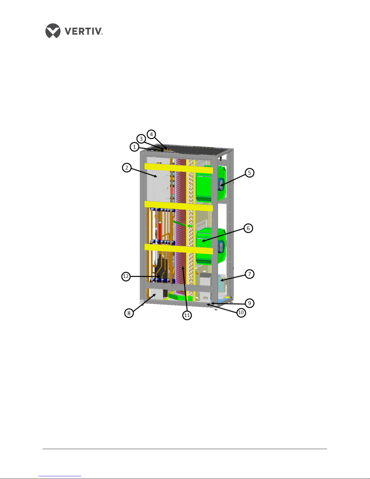
Figure 1-3 shows the various components and their respective locations:
Vertiv | Liebert CRV+ | User Manual 3
Figure 1-3 Components and their locations
Page 14
Listing 1.2
2
Electric box
Top humidifier water supply
5
EC plug fans
Item Description Item Description
1 Top electrical entrance 7
8
3
condesate-pump drain
4 Supply and Return 10
6 Electric heaters
Model Dimensions (W x D x H)(mm)
CR012HA1380S02E10000PV000
CR012RA1380S12E10000PV000
CR025HA1380S02E10000PV000
CR025RA138SS12E10000PV000
CR035HA1380S02E10000PV000
CR035RA138SS12E10000PV000
9 Bottom electrical entrance
11
12
Humidifier
Condensate pump
Bottom condensate-pump drain
Evaporator Coil
Compressor
300 x 1100 x 2000
300 x 1100 x 2000
600 x 1100 x 2000
In the following sections, take a look at the list of components used in the Liebert CRV+ Precision Air
conditioning series.
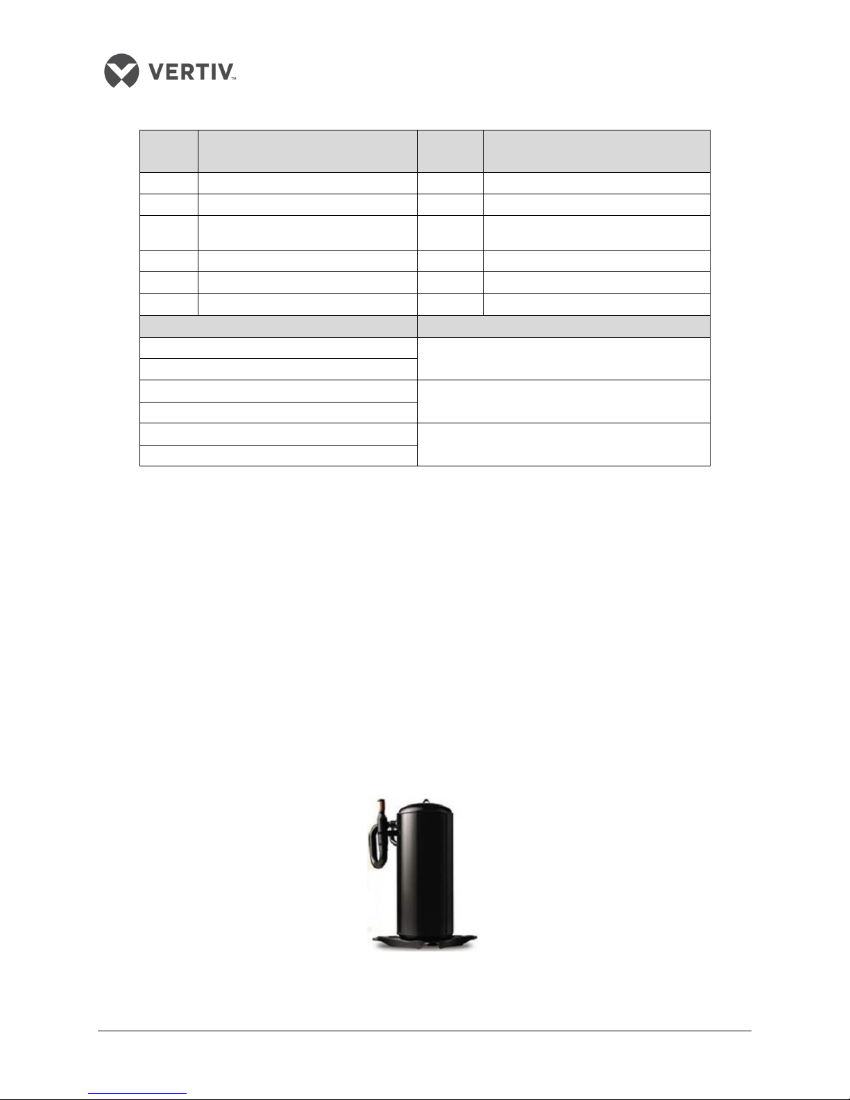
1.3.1 DC Brushless Compressor
The Liebert CRV+ series models comprise of a DC Brushless compressor which has a host of
promising features as mentioned in the following list:
Low operational noise
Rapid Cooling
Less Vibration
Moreover, there are no brushes compared to typical DC motors. Its compactness, reliability, longer life
time, and better capacity control combined with streamlined energy-efficiency make it an ideal
compressor to bank on for the CRV+ series.
Figure 1-4 shows the image of a DC brushless compressor:
Vertiv | Liebert CRV+ | User Manual
Figure 1-4 DC Brushless compressor
4
Page 15
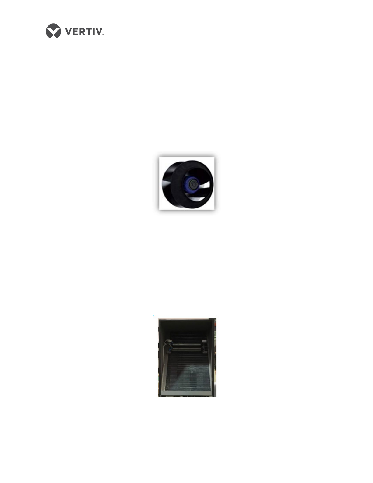
1.3.2 Fan
The EC Fans used in the Liebert CRV+ models are energy-efficient and innovative with integrated
electronics and a maintenance-free design.
Ability to regulate the airflow and reduce the fan input power leading to high energy-efficiency
Easy-to-connect facility with minimum wiring leading to high performance with a great variety of
possible air flow rates
Figure 1-5 shows the EC Fans used in the models belonging to the CRV+ series:
Figure 1-5 EC Fans
1.3.3 Evaporator
The sophisticated design of the distributor ensures that the refrigerant is distributed evenly in each loop,
thereby improving the effectiveness of the heat exchanger.
Streamlined Heat exchanger design and air distribution for optimum performance
Fin-tube heat exchanger for higher efficiency
Figure 1-6 shows the image of an Evaporator:
Figure 1-6 Evaporator
Vertiv | Liebert CRV+ | User Manual 5
Page 16
1.3.4 Electronic Expansion Valve (EEV)
The EEV is designed for modulating control of the refrigerant mass flow with precision. The EEV collects
temperature and pressure signals at the same time to accurately regulate the refrigerant flow. The EEV's
wide operating envelope also lowers down the condensing pressure, thereby resulting in significant
energy savings.
Designed for modulating control of the refrigerant mass flow with precision
Ensures effective control on super-heating at t
Better low load capacity
Designed for easy Installation-and-Service
Figure 1-7 depicts the image for the EEV used in the CRV+ Series:
he end of the evaporator
Figure 1-7 EEV
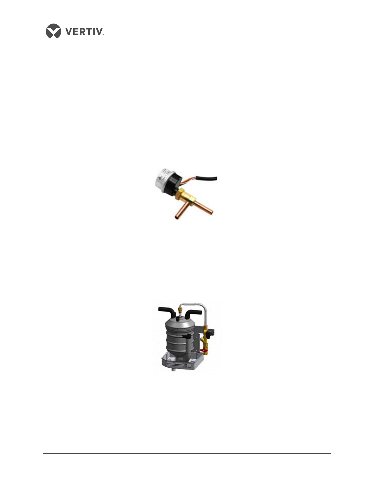
.3.5 Electrode Humidifier
1
The Electrode humidifier helps to maintain constant humidity in test chambers and is quite efficient
in small-and medium-load applications.
Figure 1-8 depicts the image of an Electrode Humidifier:
Figure 1-8 Electrode Humidifier
Vertiv | Liebert CRV+ | User Manual 6
Page 17
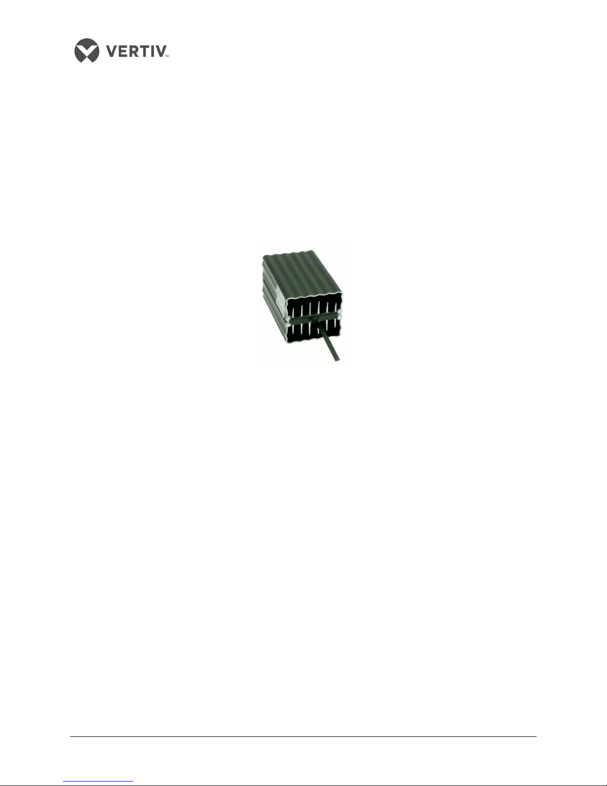
1.3.6 Electric Heater
In the CRV+ models, the PTC heaters are used as they have lower running temperatures, thereby
ensuring operational safety.
Less susceptible to overheating and long lasting due to less wear
Lower Maintenance and Smooth operation
Figure 1-9 shows an image of the Electric Heater:
Figure 1-9 PTC heater
1.3.7 Sight Glass
The sight glass is a utility for observing the refrigerant state; specifically the moisture content of the
system. If the moisture content exceeds the levels of defined standards, the color changes, thereby,
indicating irregularity in the moisture content.
1.3.8 Filter Drier
Moisture can adversely affect the operations and service life of a system in the refrigeration lifecycle. In
order to rectify that condition, filter driers are used to filter out particles, remove, and hold moisture to
prevent it from circulating through the system.
1.3.9 Micro-Controller
The Micro-Controller used in CRV+ provides a simple operational user-interface and is developed using
the latest and highly advanced PID regulation technology.
Multilevel Password protection
Self-recovery upon power failure, high-voltage & low-voltage protection
Phase loss protection
Automatic phase-sequence switching upon the anti - phase and rotate speed control of the
outdoor fan
High-end Fault diagnostic system to facilitate easy equipment maintenance
Vertiv | Liebert CRV+ | User Manual 7
Page 18
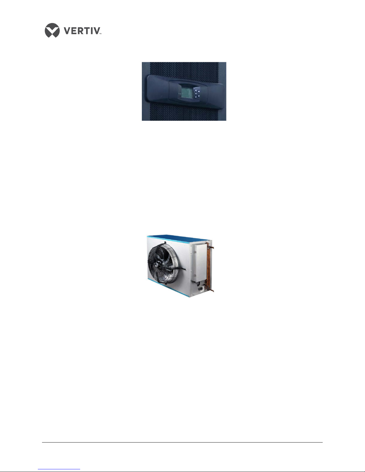
Figure 1-10 shows the image of the micro-controller:
Figure 1-10 Display panel of the Controller
1.3.10 C
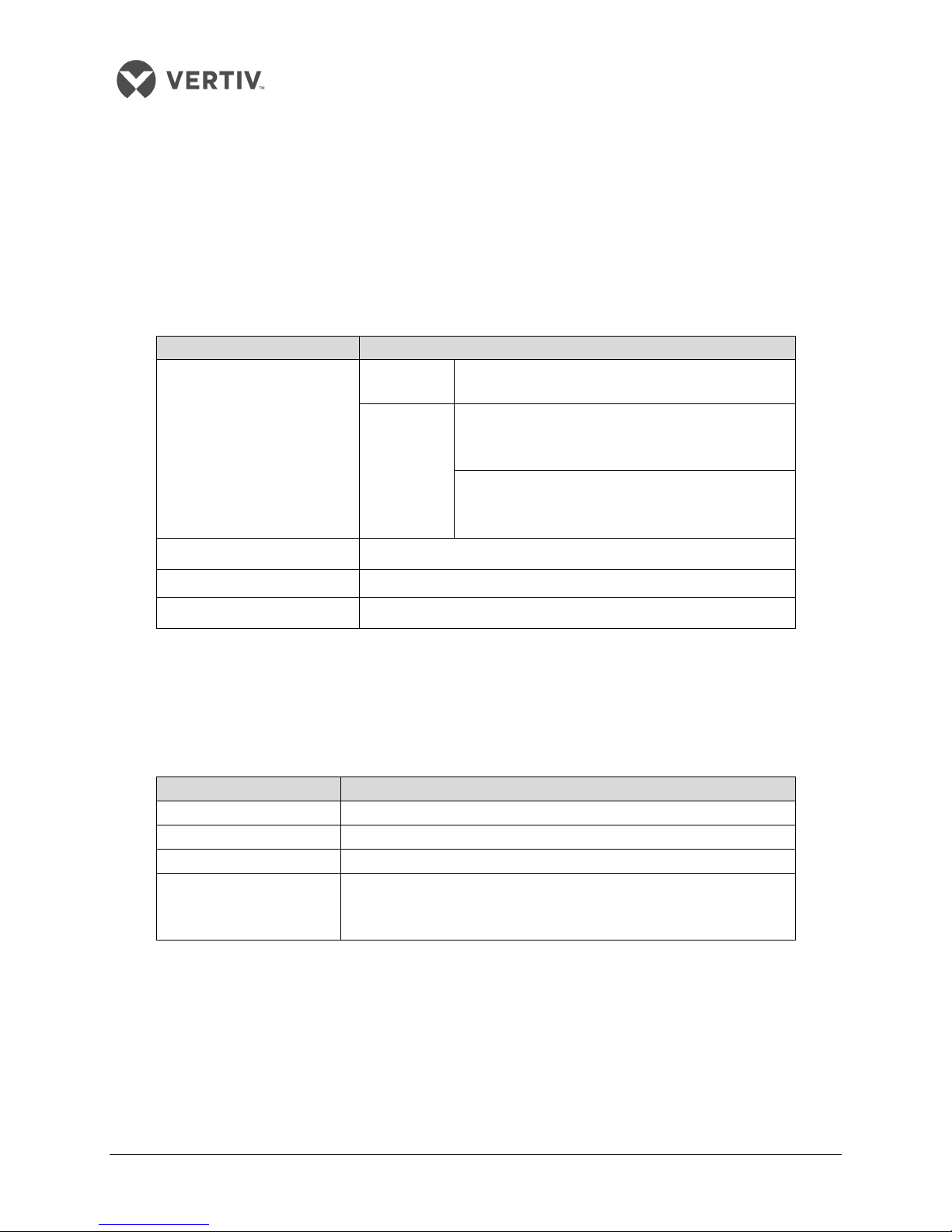
The Liebert range of air condensers offers many advantages, some of which are listed below:
Figure 1-11 shows the image of the condenser used in the CRV+ series:
ondenser
arp and Powerful design
Sh
Antirust aluminum cabinets
Low sound levels
High reliability over a wide range of ambient conditions
Figure 1-11 Condenser
For more information on the condenser, refer to the separate condenser manual which explains the
entire condenser ecosystem in detail.
1.4 Optional Equipment
The Liebert CRV+ series is compatible with multiple temperature/humidity sensors based on the
requirement.
An interesting development is the compatibility with the Liebert CRV+ series models with the Modbus
protocol. Through the configured RS 485 port or TCP/IP port, the CRV+ systems can communicate with
the host computer in addition to remotely taking charge of the host software.
Vertiv | Liebert CRV+ | User Manual 8
Page 19
1.5 Working Conditions
Item
Requirement
Item
Requirement
Storage environment
Indoor, clean (without dust)
Ambient temperature
-33°C ~ +70°C
In this section, take a look at the environmental conditions including the Operating and Storage
environment.
1.5.1 Operating Environment
The table in Listing 1.3 defines the Operating environment parameters including the Ambient
Temperature, Protection level, Altitude, and Voltage range.
Listing 1.3
Indoor 18°C ~ 40°C
CR012: -15°C ~ +45°C, if a low temperature kit is
Ambient temperature
Outdoor
Protection level (indoor unit) IP20
Altitude < 1000m. Above that, please contact Vertiv Co.
configured, the lowest outdoor operation
temperature is -34°C
CR025 and CR035: -20°C ~ +45°C, if a low
temperature kit is configured, the lowest outdoor
operation temperature is -34°C
Operation voltage range (380 ~ 415)V ± 10%, 3N ~ 50Hz / 60Hz
1.5.2 Storage Environment
The following table in Listing 1.4 defines the Storage Environment parameters including the ambient
humidity, ambient temperature, and storage time conditions.
Listing 1.4
Ambient humidity < 95%RH
Storage time
Total transportation and storage time should not exceed six months.
Otherwise, the performance needs to be re-calibrated
Vertiv | Liebert CRV+ | User Manual 9
Page 20
1.5.3 Refrigerant Charging Requirement
Brand
Logo
Note
Another essential aspect is the quality and make of the refrigerant oil. Adding poor quality oil,
counterfeit oil, or oil for a different model will damage the system. The quality issue due to
the wrong refrigerant oil will result in voiding of the warranty.
Low quality or counterfeit refr
igerant will damage the system drastically. Use the refrigerant approved by
Vertiv Co., Ltd. to avoid the system abnormality or damage caused by using other brands of refrigerant.
Listing 1.5 depicts the refrigerant brands, which are approved by Vertiv Co. Ltd.
Listing 1.5
DU PONT The DU PONT refrigerant adapts a custom made package
JUHUA
Vertiv | Liebert CRV+ | User Manual 10
Page 21

Part II
INSTALLATION
Vertiv | Liebert CRV+ | User Manual 11
Page 22
Chapter 2 Installation
The Installation process consists of the following procedures, namely-
Pre-installation
Installation Preparation
Mechanical Installation
Electrical Installation
2.1 Pre-installation
Pre-installation contains the following 3 sub sections, namely-
Transportation & Movement
Unpacking
Inspection
2.1.1 Transportation & Movement
When it comes to transporting the system, Railroad is the most preferable choice. However, if railroad
transportation is not possible, then the truck transport option is an optimal choice. One precaution is to
choose roads that do not have too many bumps and if any, avoid it as much as possible.
Liebert CRV+ systems are on the heavier side and therefore, it is recommended that equipment
like an electric forklift is utilized for these heavy duty systems.
Move the equipment to a location which is in the vicinity of the installation site.
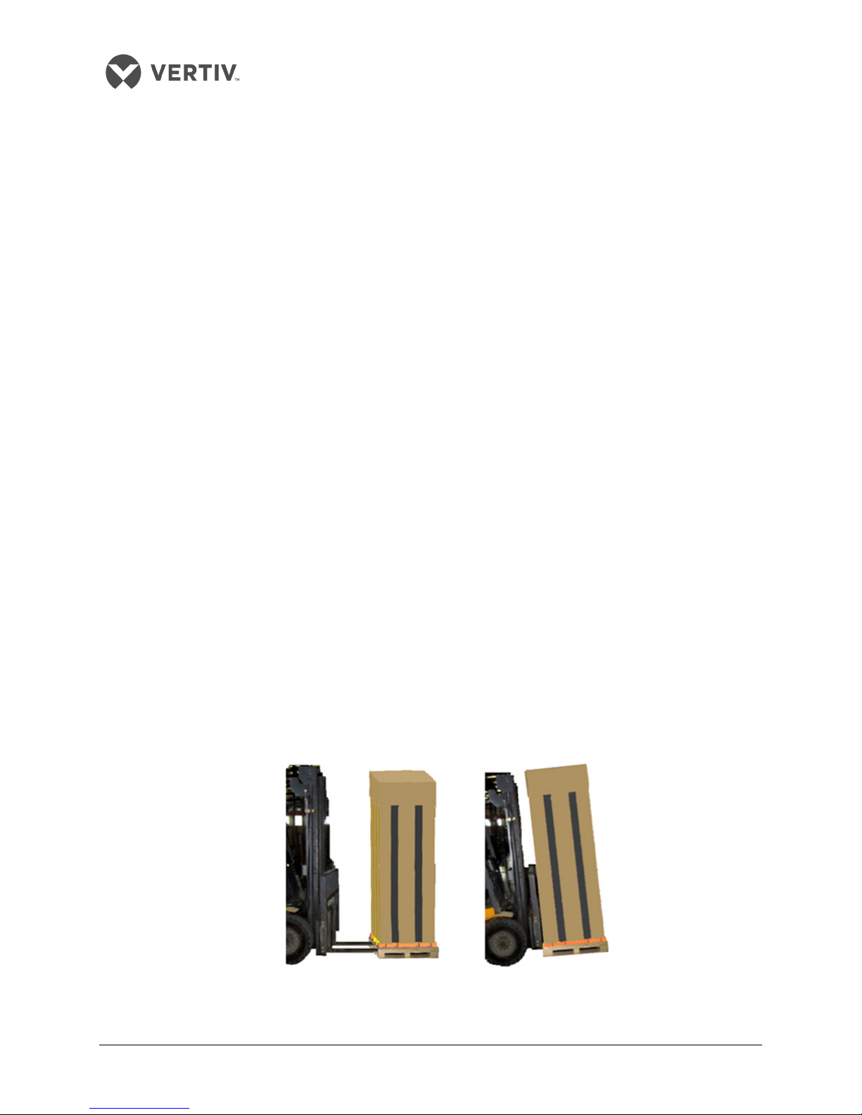
If an electric forklift is used, insert the tines of the forklift below the pallet as displayed in
Figure 2-1. Align the tines with the center of gravity to prevent the equipment from falling over.
Figure 2-1 depicts the way the tines of the forklift are inserted below the pallet and in the same
image, the graphic to the right indicates that the tines are aligned with the center of gravity to
prevent the equipment from falling over:
Figure 2-1 Moving the equipment using a Forklift truck
Vertiv | Liebert CRV+ | User Manual 12
Page 23
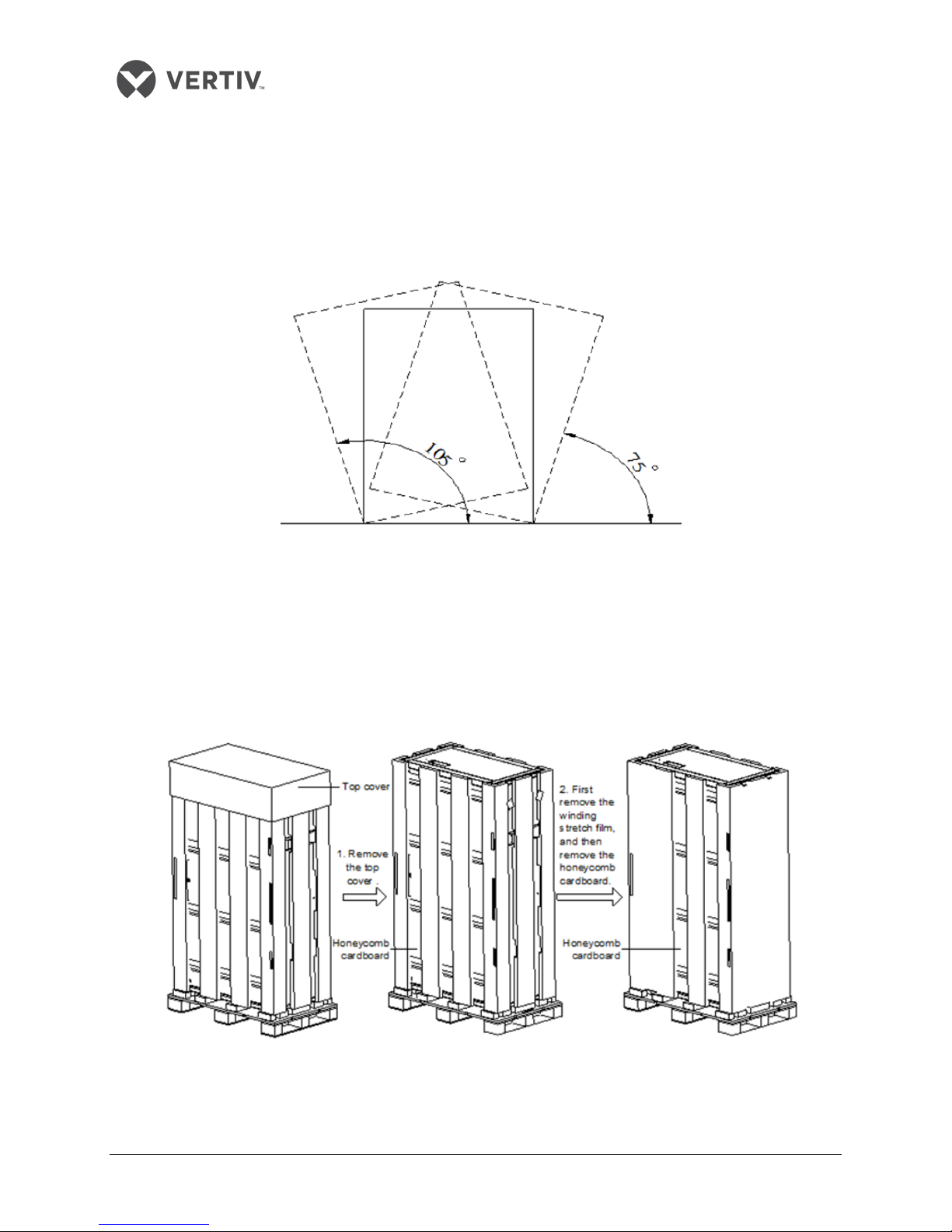
In the previous figure (Figure 2-1), the air conditioner is lifted using the forklift truck and is aligned with
the center of gravity. While moving the indoor unit, the obliquity has to be maintained with an angle of 75°
to 105°.
Figure 2-2 depicts the 75° to 105° obliquity that is suitable to move the air conditioning package to the
vicinity of the desired location:
Figure 2-2 Obliquity of the system
2.1.2 Unpacking
The cabinet uses a honeycomb cardboard and winding stretch film for packaging purposes. Shift the
product to a location closer to the final installation site prior to unpacking the unit.
Initially, remove the top cover and winding stretch film. Next, remove the honeycomb cardboard as
depicted in Figure 2-3.
Figure 2-3 Unpacking the outer package
Vertiv | Liebert CRV+ | User Manual 13
Page 24
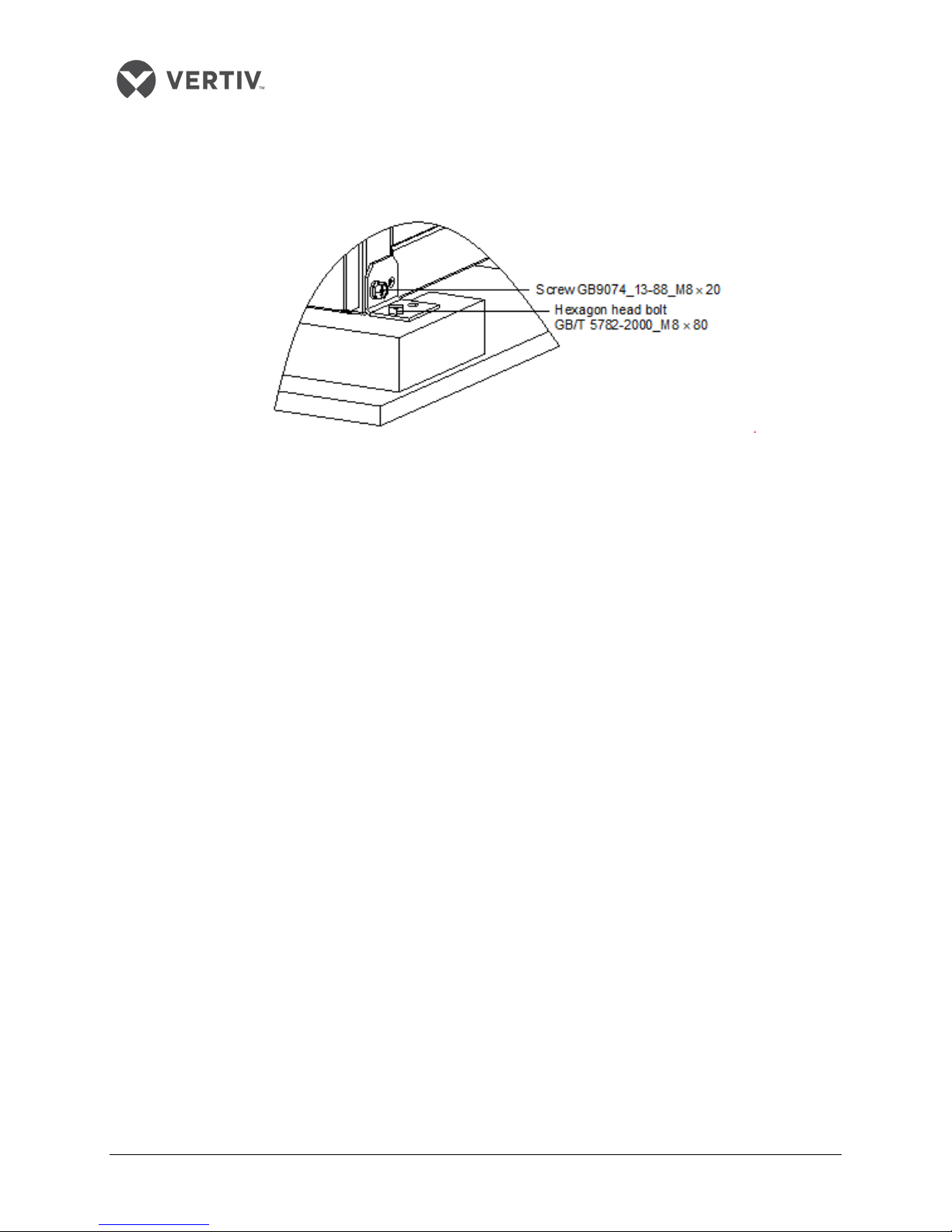
The unit is fixed on the packing pallet with M8*20 and M8*80 screws. Use a 17mm open-end spanner,
ratchet spanner, or sleeve to remove the screws.
Refer to Figure 2-4 to see the schematic diagram for the same.
Figure 2-4 Screws on the pallet
2.1.3 Inspection
Moving forward, check the system fittings and its components against the packing list to ensure that
everything is in place and the assembly is intact.
If any parts or components are missing or damaged, immediately report to the carrier about the same. If
hidden damages are observed, then contact the local offices of that carrier as well as Vertiv Co. at the
earliest.
2.2 Installation Preparation (Site Preparation)
The CRV+ series of air conditioners is streamlined for maintaining a favorable environment for data
centers, computer rooms, and similar ecosystems. Strict adherence to the installation procedures is
mandatory in order to ascertain proper installation of the air conditioner.
2.2.1 Equipment Room Requirement
The equipment room must be prepared to ensure a smooth operation flow and obtain accurate results.
The equipment room must meet the standards for appropriate ventilation and heating. The design
specifications for the air conditioners must be ideal and should match the energy-efficient design
standards.
Following are the requirements for maintaining a favorable room environment prior to installation:
The equi
The outdoor air entering in should be kept at a minimum. The outside air will add the loads of
heating, cooling, humidifying, and dehumidifying of the system. It is recommended that the
inhalation of outside air be kept below 5% of the total indoor airflow.
All the doors and windows should be properly sealed to minimize the leakage. The seams should
be as narrow as possible.
pment room should be well insulated and have a sealed damp-proof layer.
Vertiv | Liebert CRV+ | User Manual 14
Page 25
Vertiv Co.
However, if these requirements are not met, rectifications must be made on the site so that
it complies with the specified requirements and conditions. However, if the recommended
rectifications or modifications are not implemented, then
accuracy and precision of the temperature and humidity provided by the
models. One important aspect to be considered is that the indoor unit must not be used for
the outdoor environment.
recommends that the site preparation is defined as per the requirements.
Vertiv Co.
does not guarantee the
Liebert CRV+
2.2.2 Installation Space requirements
Air conditioners in the Liebert CRV+ series are advanced precision air cooling units and therefore, these
air conditioners must be installed, preferably in a row of cabinets with high heat density and in a hot aisle
and cold aisle arrangement.
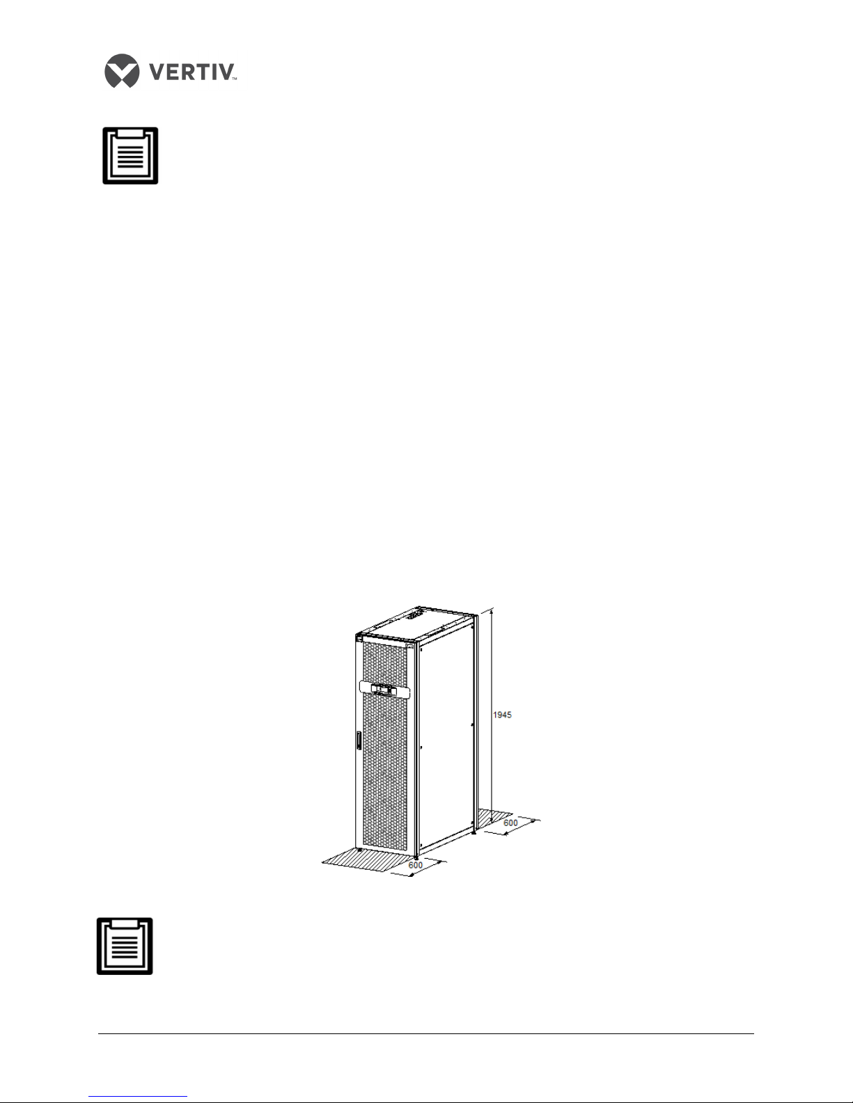
Allocate space so that it is accessible for the qualified service personnel for repairs, servicing, and
maintenance. For the CRV+ range, maintenance space must be allocated at the front and rear of the
equipment.
At the least, a space of 600 mm must be assigned for maintenance purposes in front of the system. A
minimum space of 600mm must be assigned for maintenance on the rear of the system.
The allocated space is to facilitate regular maintenance tasks such as replacement of the filter, blower,
and humidifier among others.
Figure 2-5 depicts the space allocated for servicing and maintenance.
Figure 2-5 CRV+ maintenance space
Contact the
work at an optimal level.
Vertiv Co
. team for special applications, which would need some modifications to
Vertiv | Liebert CRV+ | User Manual 15
Page 26
2.2.3 Installation Tools
Name
Drawing
Name
Drawing
Cross head
Insulated torque
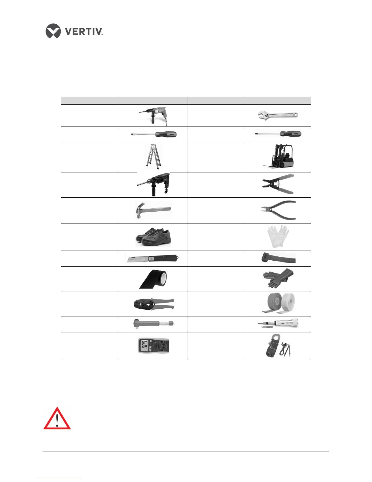
Listing 2.1 shows the generic toolsets and utilities used in the installation and maintenance process:
Listing 2.1
Electric hand drill Adjustable wrench
Slotted screwdriver
Stepladder Forklift
Drill Wire cutting pliers
Claw hammer
Insulating shoes Antistatic gloves
Electrician knife Cable ties
Insulating tape Insulating gloves
Crimping pliers Heat shrinkable tube
screwdriver
Diagonal cutting
pliers
wrench
Multimeter Clip-on ammeter
The tools mentioned in Listing 2.1 are generic and commonplace; however, depending on various factors
such as site environment, cables, installation equipment, and on-site electrical connections these tools
may vary in a real-time scenario.
Ensure that the tools used in the installation, operation, and maintenance processes are
insulated. This safety measure is important for professionals and service personnel who
work with this CRV+ range air conditioner.
Vertiv | Liebert CRV+ | User Manual 16
rque screwdriver
To
Page 27

2.3 Mechanical Installation
Proper installation is important to achieve optimal performance and prolong the product life. In
this section, the mechanical installation will be discussed in detail to help the personnel get to
grips with the installation process.
fore proceeding with the mechanical installation, the following safety precautions need to be
Be
taken into account.
Prior to installation, ensure that the installation procedures have been read and implemented as
per the requirement. (Refer to section 2.2 on Installation Preparation for the details). Check if any
modifications are made to the plumbing, wiring, or ventilation facility before mounting the
equipment. Once the installation preparations are taken into consideration, move on to the next
step in the installation process, and eventually set up the system.
The CRV+ cooling units are designed for split-floor installation. The indoor unit must be installed
on the floor of the equipment room or computer room. The outdoor unit must be installed
outdoors or on the floor of the other rooms as per the building architecture.
Industry-wide standards are followed for the selection, layout, and fixing of pipes.
Several factors such as pressure drop, compressor oil return, noise reduction, and vibration are
considered during the design and installation process.
Follow the design drawings strictly when installing the equipment. Reserve space as per the
maintenance and serviceability instructions in the previous chapter on Installation Preparation.
The manufacturer’s engineering dimension drawings must be taken as a reference while installing
the equipment.
Vertiv | Liebert CRV+ | User Manual 17
Page 28
2.3.1 System arrangement during installation
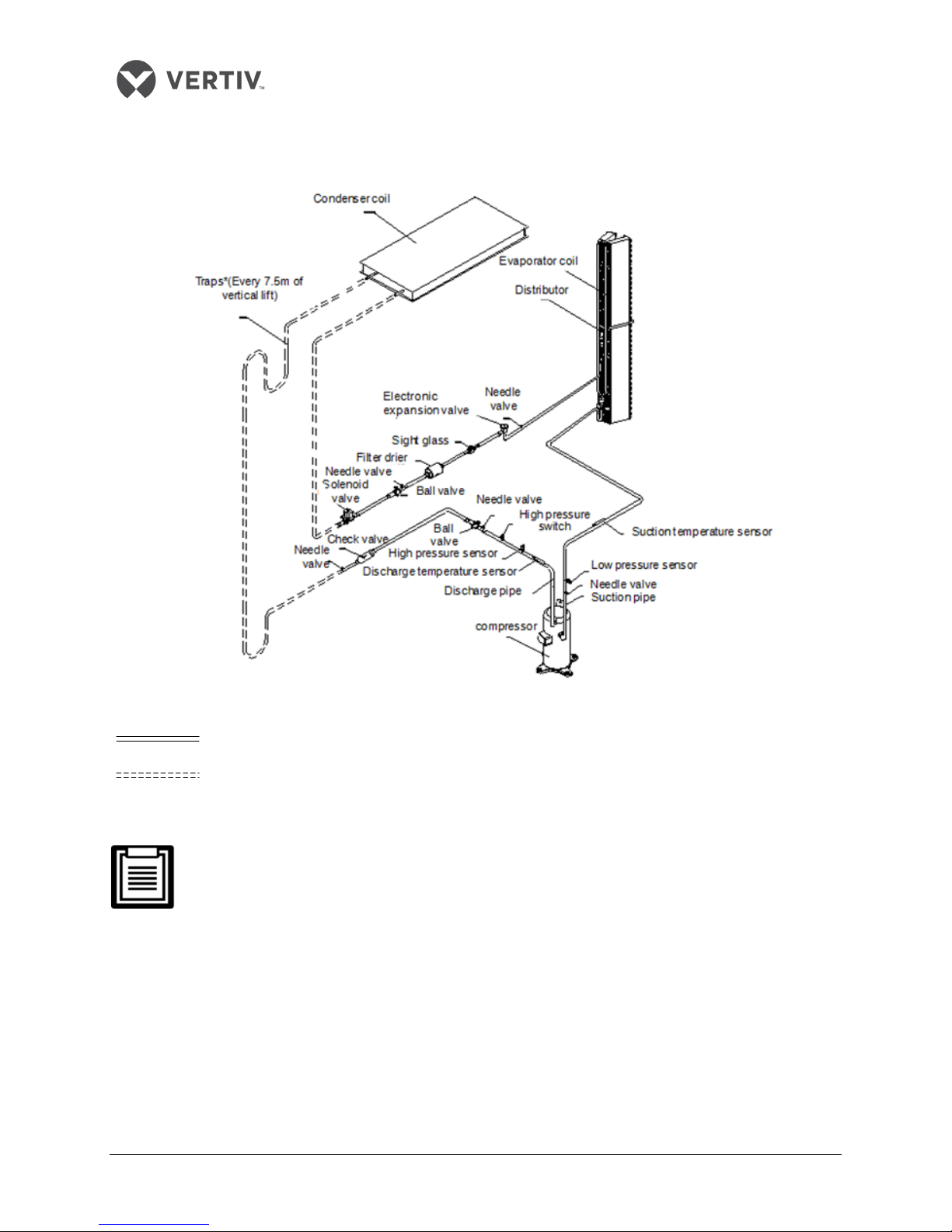
The general arrangement of the CRV+ air cooled AC unit is depicted in Figure 2-6.
Figure 2-6 System Arrangement
: Factory piping.
: Field piping (by technical personnel).
The following points should be considered before checking out the overall layout diagram:
single system is used as an example to describe the entire system.
The
Vertiv staff and qualified professionals lay out the piping in the laboratory.
Piping is done by technicians.
Components (marked with *) are not supplied by Vertiv Co. but are recommended for
proper circuit operation and maintenance.
Additional components (marked with +) are required when the equivalent length exceeds
30m.
Vertiv | Liebert CRV+ | User Manual 18
Page 29
2.3.2 System Installation Mode
Back bend (must be higher than the
highest copper pipe of the condenser)
Heat insulation floor Floor
Sealed
Raised floor
Humidifier
water in
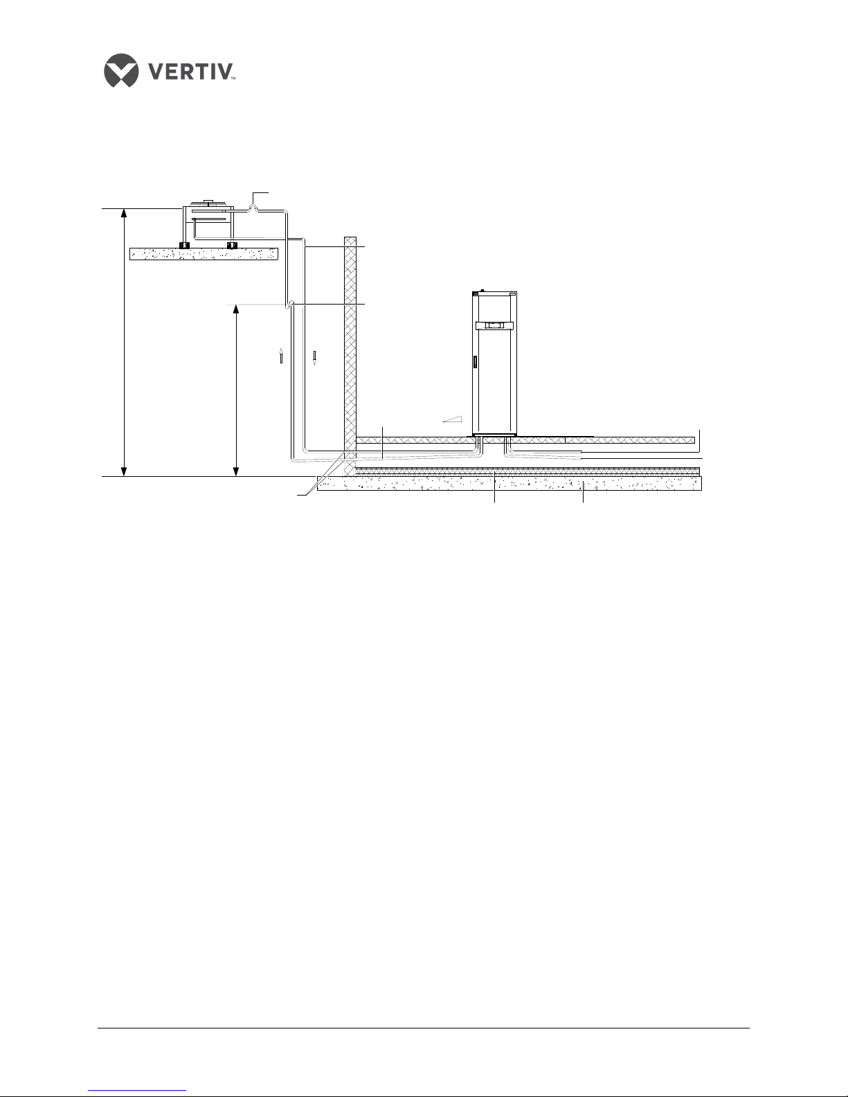
The system installation schematic diagram explains the process of installation for the Condenser:
Outdoor unit
Liquid line (avoid exposure to direct sunlight)
Indoor unit
Trap
Max. 30m
Max. 7.5m
Slope discharge
Condensed
water
Figure 2-7 Condenser is placed higher than the Compressors during installation
In Figure 2-7, the condenser is installed higher than the compressor. Therefore, an inverted back bend is
fitted to the discharge line and the liquid line of the condenser. The modification is essential as it helps
prevent the liquid refrigerant from flowing back once the condenser stops. The top end of the inverted
backbend must be installed higher than the ultimate level of the copper pipe of the condenser.
However, if the condenser is installed lower than the compressor, then there is no modification required
as it fits the bill perfectly.
Vertiv | Liebert CRV+ | User Manual 19
Page 30
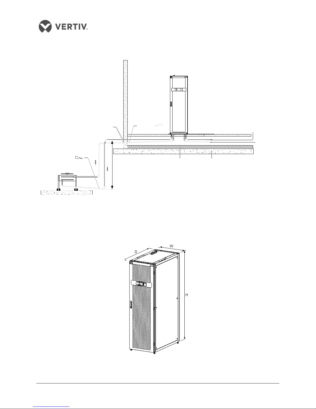
Figure 2-8 depicts the schematic diagram of system installation when the condenser is installed at a
Heat insulation floor
Floor
Sealed
Raised floor
Humidifier
water in
water out
Indoor unit
Slope liquid
Min. 8m
Slope
discharge
Outdoor unit
lower level than the compressor.
Condensed
Figure 2-8 The Condenser is lower than the Compressor during installation
2.3.3 Product Dimensions
The dimensions and weight of the indoor unit are displayed in Figure 2-9 and in the table within Listing
2.2.
Vertiv | Liebert CRV+ | User Manual 20
Figure 2-9 Dimensions of an indoor unit
Page 31

Listing 2.2
Model
Dimensions (W × D × H) (mm)
Net weight (kg)
CR012HA1380S02E10000PV000
210
CR012RA1380S12E10000PV000
215
CR025HA1380S02E10000PV000
250
CR025RA138SS12E10000PV000
260
CR035RA138SS12E10000PV000
335
Model a b c d e f g h
I
CR012
/
43
44
130
44 / /
130
205
CR025
72
88
64
131
45
161
135
131
205
CR035
48
62
45
127
49
267
360
171
120
300×1100×2000
300 × 1100 × 2000
CR035HA1380S02E10000PV000
600 × 1100 × 2000
Base Plate pipe outlet Location & Dimensions
The locations of the pipe inlets and outlets on the unit base plate are shown in Figure 2-10:
315
The following table in Listing 2.3 depicts the dimensions of the base plate pipe outlet:
Vertiv | Liebert CRV+ | User Manual 21
Figure 2-10 Base Plate Location for pipe outlets
Listing 2.3
Page 32

Top plate pipe outlet Locations & Dimensions
CR012
/
80
39
125
100
40
106
110
CR035
47
38
71
233
137
50
155
118
The locations of the pipe inlets and outlets on the unit top plate are shown in Figure 2-11:
Figure 2-11 Top plate locations for pipe outlets
The following table in Listing 2.4 depicts the dimensions of the top plate pipe outlet:
Listing 2.4
Model a b c d e f g h
CR025 55 80 39 125 100 40 106 110
Front air outlet Locations and Dimensions
The location and dimensions of the air outlet at the front are shown in Figure 2-12:
Figure 2-12 Front air outlet locations & dimensions (unit: mm)
To prevent damage of the power cable, the cable entry hole is fitted with brushing for protection.
Vertiv | Liebert CRV+ | User Manual 22
Page 33

2.3.4 Installation Procedures
Closkwise
Hexagon bolt
Fixing nut
Counter closewise
or clockwise
The feet rise or drop
The CRV+ series of air conditioners is used between racks and one side of it is adjacent to the server
cabinet. The CRV+ series of Air Conditioners is especially used in small-and medium-range data centers,
computer rooms, and similar ecosystems.
Leveling the cabinet
Once all the components of the cabinet have been installed, level the cabinet. The following section is a
step-by-step illustration of the process of leveling the cabinet:
Place the cabinet in the desired location (preferably an open ground). Use a movable wrench to
loosen the fixing nuts on the four foot bolts in a clockwise sequence.
Rotate the hexagon bolts on the bottom of the feet clockwise or counter-clockwise till the feet
rises or drops to an appropriate position. Use a gradienter to ensure that the cabinet is in a
uniform level state.
Refer to the Figure 2-13
to understand the process better:
Figure 2-13 Leveling the cabinet
Screw down the fixing nuts on the feet bolts counter-clockwise and the leveling gets completed. If
the machine room has a mounting bracket, and its width does not exceed 30mm, remove the feet
and fix the cabinet onto the mounting bracket.
Vertiv | Liebert CRV+ | User Manual 23
Page 34

Removing the Feet and Fixing cabinet
Top fixing hole
Top fixing hole
Bottom fixing hole
Bottom fixing hole
Before explaining the task of removing the feet and eventually fixing the cabinet, it is vital that
2 persons will be required for this operation to avoid personal injury and cabinet damage.
Following are the instructions to be followed for removing the feet and fixing the cabinet:
Removing the feet
Use a moveable wrench to loosen the fixing nuts on the four fleet bolts in a clockwise sequence.
Rotate the hexagon bolts on the bottom of the feet clockwise till the feet drops from the cabinet
frames.
Fixing the cabinet
The cabinet provides two holes (diameter: 13.5 mm) respectively on its top, bottom, front, and rear as
depicted in Figure 2-14.
Install bolts in the four holes at the bottom to fix the cabinet onto the floor bracket of the machine
room.
Install bolts in the four holes at the top to fix the cabinet to connect the cabinet with the top
bracket of the machine room.
Vertiv | Liebert CRV+ | User Manual 24
Figure 2-14 Fixing holes of the cabinet
Page 35

Cabinet Connection
Cabinet
connector
Cabinet
connector
A
A amplified
Mounting screw
GB819_1_2000_M5x12
Cabinet connector
416 1100
The cabinet connectors come along with the accessories. Connect the unit with adjacent cabinets using
the cabinet connectors. The following section depicts the procedures for connecting the cabinet:
Before connecting the cabinet, level the cabinet as mentioned in the earlier section (Refer to
section Leveling the cabinet for in-depth information).
Loosen the fixing screw of the cabinet connector on the frame of the cabinet.
Rotate the cabinet connector 90 ° to the horizontal position. Use M5 countersunk head screws to
fix it on the cabinet frame. (Side of the door lock) as depicted in Figure 2-15.
Figure 2-15 Rotating the Cabinet connector
Use the M5 countersunk head screws to fix the cabinet connector (L-shaped) in the installation
holes of the cabinet frame (side of the hinge) and rack frame adjacent to the cabinet as depicted
in Figure 2-16.
Figure 2-16 Schematic diagram for connecting the cabinet
Install the other 6 cabinet connectors based on the same method.
Vertiv | Liebert CRV+ | User Manual 25
Page 36

2.3.5 Piping
A
A amplified
Fixing flake of the filter
Mounting screw
GB9074_4_88_M4x12
The pipes to be included in the Piping process of the AC are listed below:
Condensed water drainage pipe of the indoor unit;
Water inlet pipe of the electrode humidifier;
Connection of the copper pipe (discharge pipe and liquid pipe) between the indoor unit and
outdoor unit;
Pipe extension kit (optional).
The following points need to be taken into consideration during the Piping process:
All the joints of the refrigerating pipes must be silver-brazed.
The selection, layout, and fixing of the pipes will conform to the industry standards and
norms.
Vacuum pumping and refrigerant charging operations, and procedures must conform to the
industry standards.
Pressure drop, compressor oil return, noise return, and vibration must be considered during
the designing and installation process.
Removing Filters
Before the connection of the pipes in the indoor unit, the filters need to be removed.
Open the rear door of the cabinet to reveal the 2 filters, namely- the top and bottom filters.
Next, proceed to remove the fixing flake of the top filter. Prior to the removal of the fixing flake,
the screws of the flake need to be loosened. Then, the fixing flak will be removed, followed by
removing the top filter.
Use the same method to remove the bottom filter.
Figure 2-17 depicts the process of removing the filters:
Vertiv | Liebert CRV+ | User Manual 26
Figure 2-17 Removing the Filters
Page 37

Connecting the condenser water drainage pipe of the indoor unit
The Condensed water of the electrode humidifier and the evaporator converge to a common water tray
following which it is drained through the drainage pipe of the drain pump.
The unit is configured to adopt the top drain mode by default; therefore, connect the drainage
pipe of the pump upwards to the top drainage copper pipe.
Fix the drainage pipe to the drainage pipe connector with the hose clamps available in the
shipped accessories. The torque of the hose clamp is 15 kg cm.
Connect the drainage pipe to the drainage hole on the top of the cabinet.
To drain water from the bottom, direct the soft drainage pipe through the drainage hole of the
pump.
Fix the pipe to the copper pipe connector with the hose clamp. Moving forward, connect it to the
outer drainage pipe.
The outer diameter of the copper pipe is 12.7 mm and internal diameter of the soft pipe is 9 mm.
However, if the unit is not configured with a pump, the drainage pipe of the water tray should go through
the drainage hole of the tray and connect to the outer drainage pipe. The Trap is essential to drain the
condensate water.
The following points are to be taken into consideration about the trap:
Adopt a galvanized steel, PVC, or polyethylene pipe with a fair amount of flexibility
Allow a tilt of 2% towards the direction of the drainage flow.
The trap is mandatory and should be located 30 cm below the water tray. The tray must be kept under
the
movable floor.
Figure 2-18 Process of draining the Condensate water
Vertiv | Liebert CRV+ | User Manual 27
Page 38

Don’t cut off the brackets of the trap lest the smooth draining gets destroyed
Filling water to the trap before the unit is powered on
Use a Teflon belt between the flexible pipes and connector to avoid water leakage
The electrode humidifier contains flowing hot water, thus the plastic pipe must be resistant
to heat higher than 90° C
Figure 2-19 Connection of drainage pipes
Connecting the Water Inlet Pipe of an Electrode Humidifier
Water pipes should be connected for the electrode humidifier.
By default, the unit adheres to a top water inlet mode. If the water has to be filled from the top,
there is no need to change the water inlet pipe in the unit. In this case, connect a water inlet pipe
to the water inlet hole on the top of the cabinet.
However, if the water has to be filled from the bottom, unscrew the connector of the water inlet
soft pipe of the humidifier. The water inlet soft pipe needs to be routed through the rubber plug
hole close to the humidifier and connected to the outer water inlet pipe. Screw down a threaded
connector onto the water inlet pipe to complete the fixing process. Other connecting modes can
also be selected by the engineering methodologies, but the connections must be sealed to avoid
water leakage. The pressure range of the main pipe should be in the range of 100kPa – 700kPa.
In some cases, the process needs to be in compliance with the local laws and regulations
resulting in the introduction of some other components.
Vertiv | Liebert CRV+ | User Manual 28
Page 39

Figure 2-20 depicts the connection of the bottom water inlet pipe of the electrode humidifier:
Model
CR012
CR025
CR035
10m
16
12.7
16
12.7
19
16
30m
19
12.7
22
16
25
19
50m*
19
16
22
19
25
22
Water inlet
soft pipe
Water inlet
hole
Top water inlet
copper pipe
Figure 2-20 Connection of bottom water inlet pipe of electrode humidifier
Connecting the Copper pipes between the Indoor and Outdoor unit
The indoor and outdoor units are connected through welded copper pipes. Considering the effect of the
pipe diameter on the system pressure drop, the pipe diameter of the indoor unit and outdoor unit should
be determined by the specifications mentioned in the table under Listing 2.5. Alternatively, contact the
Vertiv support office to seek the help of the technician for gauging the length and diameter.
Listing 2.5
Pipe length D L D L D L
20m 16 12.7 19 16 22 19
40m* 19 16 22 16 25 19
A pipe extension kit is required for Equivalent Length marked with *.
D: Discharge line; L: Liquid Line
Consult Vertiv Co.If the pipe length exceeds 50m or 30m.
If the outdoor environment is lower than -20 °C, a low temperature kit is required. Therefore,
consult Vertiv Co. for the same.
Vertiv | Liebert CRV+ | User Manual 29
Page 40

The unit has refrigerating pipe connectors and labels on its top and bottom as shown in Figure 2-21 and
进水孔
排水孔
液管孔
排气管孔
进线孔
进线孔
Cable entry hole
Discharge pipe hole
Cable entry hole
Liquid pipe hole
Drainage hole
Water inlet hole
Drain hole
Cable entry hole
Liquid pipe hole
Discharge pipe hole
Figure 2-22.
During welding, do not burn the labels. The labels assist and point out the connections to the discharge
pipe and liquid pipe of the indoor unit. The horizontal sections of the discharge pipes must be tilted
downwards from the compressor with a slope of at least 1:200 (5mm down for every 1m run). The
discharge pipes must be insulated from heat at the location they are routed in the conditioned space
(including the raised floor).
Figure 2-21 Top pipe connectors
For bottom piping, before welding the compressor discharge pipe and liquid pipe, follow the
requirement labeled on the copper pipe; Cut the copper pipe using a cutter (a little bit of
the compressor lubricating oil may leak); however, do not weld the copper cap on the seal
directly as it may result in heating of the oil following which it may catch fire.
The exposure time of the system pipes should not exceed 15 minutes. If exposed for too
long, it will lead to the POE refrigeration oil being affected with damp. It may result in an
adverse effect on the life of the key components and the stability of the system operation.
Vertiv | Liebert CRV+ | User Manual 30
Figure 2-22 Bottom Pipe connectors
Page 41

Installing Pipe Extension Kit (for site installation)
There are instances where the one-way equivalent length of the pipe exceeds 30m. Or suppose the
vertical distance between the condenser and the indoor unit exceeds the value in the first table in the
following Listing 2.6.
Listing 2.6
Vertical distance between the Indoor and Outdoor unit
Positioning of the Outdoor Unit Height
Outdoor unit is higher than the Indoor unit Maximum : + 30m
Outdoor unit is lower than the indoor unit Minimum : - 8m
Equivalent length of the partial components
Outer diameter (OD) of the liquid pipe
(inches)
3/8 0.21 0.10 0.76
1/2 0.24 0.12 0.76
5/8 0.27 0.15 0.76
3/4 0.3 0.18 0.76
7/8 0.44 0.24 1.1
1-1/8 0.56 0.3 1.4
90° bend 45° bend T Type 3-way
Equivalent length (meters)
A trap must be installed every 7.5m of the vertical distance. Please consult Vertiv for such
specific inquiry and installation.
There is no necessity of cutting the indoor unit pipes while installing the solenoid valve.
After t
he entire system is installed, open the ball valve to keep the pressure and carry out the vacuum
operation, thereby avoiding the moisture absorption of the compressor refrigeration oil, Thus, it accounts
for operational safety and also extends the service life of the compressor (For electrical connections
related to the pipe extension kit, refer to the Electrical Installation section).
Take a look at the procedure for installing the Solenoid valve in the liquid pipe:
The solenoid valve must be as close to the indoor unit as possible. The valve body and coil of the
solenoid valve are separated when the valve is shipped out.
1) Mount the valve body horizontally in the refrigerant pipe as shown in Figure 2-23. Pay attention to
the arrow on the valve body as the arrow indicates the flow direction of the refrigerant in the valve.
Ensure that the arrow points towards the indoor unit.
Vertiv | Liebert CRV+ | User Manual 31
Page 42

Figure 2-23 Installing the Solenoid valve horizontally
2) After welding, install the coil and remove the cover of the wiring terminals. Direct the cable through
the cable hole in the cover and plug the two terminals and reinstall the cover.
Figure 2-24 shows the process of connecting the cables of the solenoid valve in a liquid pipe:
Figure 2-24 Connecting the cables of the Solenoid valve
3) Finally, clip the coil of the valve body, press the coil tightly to ensure complete contact between the
coil and valve body as displayed in Figure 2-25.
Charging Refrigerant and Adding Refrigeration Oil
The Liebert CRV+ air conditioners come pre-charged in the factory with 2Bar Nitrogen. The table in
Listing 2.7 indicates the standard charged amount. The users can determine the charging amount of the
Vertiv | Liebert CRV+ | User Manual 32
Figure 2-25 Fixing the coil
Page 43

refrigerant according to the system configuration and the length of the connection pipes between the
Outdoor unit model
LSF 12
LSF32
LSF38
LSF42
LSF52
LSF76
Recommended charging amount
2.44
3.24
3.93
4.4
5.73
6.39
Indoor unit model
CR012
CR025
CR035
Standard charging amount
2.41
4.52
5.24
16
0.174
22
0.321
25
0.431
28
/
indoor and outdoor unit.
The tables in Listing 2.7 depict the recommended charging amount of the outdoor unit and the
recommended charging amount for the indoor unit.
Listing 2.7
Recommended refrigerant charging amount of the outdoor unit
Recommended refrigerant charging amount of the indoor unit
The refilling amount of the refrigerant is calculated using the following formula:
Refrigerant refilling amount (kg) = Recommended refrigerant charging amount of outdoor unit+
recommended refrigerant charging amount of indoor unit+ refrigerant refilling amount of per meter
liquid pipe (kg/m) × total length of liquid pipe (m)
Refer to the table in Listing 2.8 for the refrigerant refilling amount of per meter liquid pipe for different
ODs:
Listing 2.8
Liquid pipe OD (mm) Refrigerant refilling amount of per meter liquid pipe (kg/m)
12.7 0.107
19 0.245
The refilled refrigerant will dilute the POE oil in the system and plays a major role in the lubrication and
cooling effects of the POE oil. Thus, it is for this purpose that the refrigerant oil must be added.
Vertiv | Liebert CRV+ | User Manual 33
Page 44

The refrigeration oil used in the Liebert CRV+ air conditioner is depicted in the table in Listing 2.9:
Unit model
Types of refrigeration oil
CR035
PVE (FVC68D)
Refrigeration oil adding amount with different pipe length
Liquid
CR012
Refrigeration oil
16
15
30
45
60
Liquid
CR025
Refrigeration oil charging is not
16
11
19
28
37
19
35
48
60
72
Liquid
CR035
Refrigeration oil charging is not
19
12
24
37
49
Listing 2.9
CR 012 PVE (FV505)
CR025 POE (RL32H)
Table depicting the amount of refrigeration oil to be added
(length unit: mm, refrigeration oil unit: ml)
pipe OD
(mm)
12.7
pipe OD
(mm)
12.7
pipe OD
(mm)
16
22 39 55 71 87
10 20 30 35 40 45 50
Refrigeration oil charging is not
needed
10 20 30 35 40 45 50
Refrigeration oil charging is not
needed
10 20 30 35 40 45 50
Refrigeration oil charging is not
needed
charging is not needed
needed
needed
15 30
Consult Vertiv Co. for adding the refrigeration oil
32
13
Do not use poor quality refrigeration oil as it can damage the system
Select the right make and type of refrigeration oil depending on the model.
If any error or damage occurs due to adding the incorrect make and type of oil, the warranty
will be void.
2.3.6 Removing Transportation Fastener and Vibration Absorber
Certain fasteners and vibration absorbers are mounted on the equipment to protect partial components
from getting damaged and distorted due to bumping, impact, and resonance.
Vertiv | Liebert CRV+ | User Manual 34
Page 45

Removal of these fasteners and absorbers is necessary before installation and commissioning.
M4 screw
(6 pcs)
Removing Pipe fixity
If the copper pipe gets close to the metal plate, it may result in wear and tear of the copper pipe. To
prevent this from occurring, vibration absorbers are fitted between them. However, these objects need
to be removed and then the area must be cleaned prior to installing and commissioning.
Removing limiting piece of the electrical control box
The electric control box may move during transportation. To prevent this abrupt movement, a limiting
piece of the electric control box is installed before delivery. The limiting piece has to be removed before
operating the unit so that the maintenance personnel can slide out the electrical control box during
maintenance.
Adjusting the wind-leading grill
Adjust the installation direction of the wind-leading grill to lead wind to the left or right depending on the
installation location of the Liebert CRV+ series air conditioners. The wind-leading grill is composed of
several pieces. Remove the screws on both sides of the single piece of the wind-leading grill, rotate it by
180°. Install it back to change the wind direction.
Figure 2-26 shows the mounting screws of a single piece of the wind-leading grill:
Sealing the holes of the top plate of the cabinet
Holes are reserved at the top of the cabinet to facilitate smooth on-site installation as well as the
connection of the rack on the top of the machine room. After the cabinet is installed on the site, seal the
remaining holes using rubber plugs and bolts. Use M13.5 rubber plugs to seal four holes at the top of the
cabinet and M12*30 bolts to seal 8 holes at the top plate of the cabinet. This prevents water from
entering the cabinet.
Vertiv | Liebert CRV+ | User Manual 35
Figure 2-26 Fixed mode of the wind leading grill
Page 46

Figure 2-27 depicts the schematic diagram of sealing the holes on the top plate of the cabinet.
Use the provided four M13.5 rubber plugs to seal the holes
Use the provided eight M12 × 30 bolts to seal the holes
Item
Result
Drainage pipe is connected
All pipe connectors are tight
F
igure 2-27 Sealing the top holes of the cabinet
2.3.7 Checklist for completed mechanical installation
Following are the points in the checklist (Refer Listing 2.10) that need to be verified and confirmed to
ensure that the mechanical installation was implemented successfully:
Sufficient space is kept for maintenance, according to the user manual.
The equipment is placed vertically and mounting fasteners are fastened
The pipes between the indoor unit and outdoor unit are completed. The ball valves
of the indoor unit and outdoor unit are fully opened
The wind direction of the wind-leading grill has been adjusted (if required)
Water supply pipe is connected to the electrode humidifier
The fasteners used for transportation have been removed
After installation, foreign materials in and around the equipment are removed
(such as shipping materials, construction materials, tools, and so on)
Listing 2.10
Vertiv | Liebert CRV+ | User Manual 36
Page 47

As soon as the mechanical installation has been implemented and completed accurately, then
the electrical installation of the product and its components can be carried out.
2.4 Electrical Installation
In this chapter, the electrical installation of the CRV+ air cooled units is explained in-depth to
help users get to grips with the various tasks which include the task introduction, notes, and
cable connections of the indoor unit apart from the checklist.
The air conditioners in the Liebert CRV+ series are professional devices used in industrial,
commercial, or other professional occasions. It is not tailored for the general public. The total
rating power is larger than 1 kW and is in with the IEC61000-3-12 standard. A port of less
than a 350 short circuit requires is required between the user power and the grid.
Permission is required from the power supply department to ensure that the air conditioner
is connected to a power no less than 350 circuit ratio.
2.4.1 On-site Wire connections
Following are the wires to have to be connected in/on the site:
Power cable and control cabinet of the indoor unit
Solenoid valve cable of the pipe extension kit (an optional requirement)
Outdoor unit (air-cooled), control Signal and Power cable
Input and Output control the cable of the unit
2.4.2 Installation Notes
The connections of all the power cables, control cab
compliance with the local and national electrical regulations.
Observe the unit nameplate for the full load current. The cables sizes must meet the conditions as
specified in the local wiring protocols and rules.
Mains supply requirement: (380 to 415) V ± 10%; 50 Hz/60-Hz, 3N-
The power soft cable is a Y-type connection. If damaged, it has to be replaced immediately to
eliminate the dangers. The replacement procedure must be carried out by an authorized
professional or experienced service personnel.
The electrical installation and maintenance must be carried out by an authorized personnel or a
trained engineer well-versed with the inner workings of the electrical connection (For example,
service engineer from the manufacturer’s side).
Prior to the wiring, a voltmeter must be used to measure the power supply voltage and ensure that
the power supply has been switched off.
Use screws, guide rails, or other modes to fix the device firmly during the installation process to avoid
movement or shaking during the start-up or operation mode.
For the air conditioner configured with EC fans, the unit power grid adheres to the TN or TT star
connection power distribution system. However, if there is a need to configure another type of
power grid, contact the Vertivsupport team for the same.
les, and ground cables should be in
Vertiv | Liebert CRV+ | User Manual 37
Page 48

An appropriate all –pole disconnection device must be supplied.
SCCR of the CRV+ air cooled unit - 5 kA
The power soft cable should not be lighter than an ordinary PVC-sheathed according to the 53
line according to GB5023.1(idt IEC60277)
For appliance of outdoor, the power cable should be not lighter than Chloroprene rubber
sheathed flexible cord which is 57 line according to IEC 60245.
2.4.3 Connecting cables of the Indoor unit
This section deals with the different types of connections related to the indoor unit, namely–
Electrical port location of the indoor unit
Connecting the Power cables of the indoor unit
Connecting the Control cables
Connecting the Solenoid valve of the Pipe extension kit (Optional)
Electrical Port location of the indoor unit
For any model in the CRV+ series, open the back door of the indoor unit following which the
specific layout and locations of the low voltage components can be viewed as depicted in Figure
2-28. For detailed layout information on low voltage components, refer to the labels pasted on
the cabinets and units.
Figure 2-28 Unit electrical control box and cable connection (open the back door 120°)
MCB current
Model MCB Current(A)
CR012 NDM1-63C32/3 32
CR025 NDM1-63C40/3 40
CR035 NDM1-63C50/3 50
Vertiv | Liebert CRV+ | User Manual 38
Listing 2.11
Page 49

Connecting the Power cable of the Indoor unit
Standard
The specific location of the power port of the indoor unit is depicted in Figure 2-28. Connect the
supply terminals L1-L3,N and PE to their respective counterparts of the external power supply
res
pectively.
Fix the input cables to the cable clamp, located on the inner side panel of the unit. The top cable
entry hole and bottom cable entry hole as depicted in Figure 2-29.
For the cable specifications, refer to the full-load current (FLA) described in the table within
Listing 2.12.
The cable sizes must strictly meet and adhere to the local wiring regulations and protocols as
it supersedes every type of connection.
Full Load current (unit A)
Model
CR012HA1380S02E10000PV000 19.1 19.1 / /
CR012RA1380S12E10000PV000 19.1 / / /
CR025HA1380S02E10000PV000 24.9 24.9 26 26
CR025RA138SS12E10000PV000 26 / / /
CR035HA1380S02E10000PV000 31.6 46.6 42.3 46.6
CR035RA138SS12E10000PV000 46.6 / / /
Figure 2-29 Top and bottom cable entry holes
Listing 2.12
Standard
model
Standard
model with
electric
heater
Standard
model with
humidifier
model with
electric
heater &
humidifier
Vertiv | Liebert CRV+ | User Manual 39
Page 50

The location of the terminal block for cable connections in the site is depicted in Figure 2-28. The
amplified view of the terminals is shown in Figure 2-30.
Figure 2-30 Terminal Block for cable connection in the site
The connection personnel must take anti-static measures before connecting the control
cables
Water-under-floor sensor
If a water-under-floor sensor is equipped, connect one end of the sensor to terminal 51# and the other
end to common terminal 24#.
Each unit can be connected with multiple sensors in parallel, but there would be only one water-underfloor alarm.
SIC card
If a SIC card is equipped, connect A#, B#, GND#, and 12# on the SIC card to the respective counterparts
on the terminal block. Refer to Appendix 1 Circuit Diagram fo
r in-depth information.
Vertiv | Liebert CRV+ | User Manual 40
Page 51

Rack sensor
Sensor
1 2 3 4 5 6 ID
传感器
Sensor
1.5m
1.5m
Each unit can be connected with a maximum of 10 temperature sensors. It is recommended that the
sensors be located in front of the heat loads to achieve the most precise temperature. If the sensors are
connected in series (see Figure 2-31), each temperature sensor monitors the temperature of air entering
each rack, and the read temperature value is used to control unit operation. The standard location of the
sensor is 1.5m height. Therefore, the sensors should be placed in positions as depicted in Figure 2-31, or
the devices cannot operate appropriately.
Figure 2-31 Layout figure of rack sensors
Following is the procedure to connect sensors for Liebert CRV+ models:
Insert the connector of the rack temperature sensor in the TB3 point. On connecting the cable,
route the cable through the top or bottom of the unit following which it should be connected to
the first sensor. Connect the first sensor to the second sensor. Thus, the sensors are connected in
a chain.
Fix the temperature in front of the hottest source inside the rack. Do not fix it in front of the
empty sub-rack. Affix the sensor on the rack surface using the magnets provided in the kit. Th
ensor must be fixed in a position that is mostly short of cool air.
s
Rack temperature sensor IRM-S0
Rack temperature 1 0 0 0 0 0 1 1
Rack temperature 2 0 0 0 0 1 0 2
Rack temperature 3 0 0 0 0 1 1 3
1 address settings are depicted in the table in Listing 2.13.
Listing 2.13
ON — “1”;
OFF — “0”
e
Rack temperature 4 0 0 0 1 0 0 10
Vertiv | Liebert CRV+ | User Manual 41
Page 52

Sensor
1 2 3 4 5 6 ID
Rack temperature 5 0 0 0 1 0 1 11
Rack temperature 6 0 0 0 1 1 0 12
Rack temperature 7 0 0 0 1 1 1 13
Rack temperature 8 0 0 1 0 0 0 20
Rack temperature 9 0 0 1 0 0 1 21
Rack temperature 10 0 0 1 0 1 0 22
ON — “1”;
OFF — “0”
Remote Shutdown
As depicted in Figure 2-30, terminals 37# and 38# can be connected to the remote shutdown switch.
The terminals must be shorted before delivery. If a remote shutdown signal is to be connected, remove
the short-connect cable.
Closing the terminals 37# and 38# will shut down the unit.
Control signals of the outdoor unit
Terminals 70# & 71# are the control signal input terminals of the outdoor unit. Their On and Off state is
the same as that of the compressor 2#. They can be connected to the compression rotation speedcontrol terminals on the control board of the outdoor unit. However, connecting them is an option
depending on the requirement.
External Common Alarm
Terminals 75# and 76# can be connected to the external common alarms. They generate signals to
external alarm devices such as an alarm indicator. When the critical alarm occurs, the contact will be
closed to trigger remote alarms, send signals to the building management system, or dial the paging
system automatically.
The users have to obtain the power supply of external common alarm system. For an in-depth definition
of the other terminals, refer to the Circuit Diagram
the Appendix-1.
in
Connecting the Solenoid valve of the Pipe Extension kit - (Optional for Site Installation)
The solenoid valve of the pipe extension kit consists of 2 control cables which are connected to their
respective terminals of the control board. For more specific connecting points on the interface board,
refer to the connecting terminal number of the liquid route solenoid valve depicted in the Circuit
Diagram in the Appendix-1 section.
Vertiv | Liebert CRV+ | User Manual 42
Page 53

Checklist for the Completed Installation
Items to be inspected
Results
No open-circuit or short-circuit exists in the electrical connection
The control connections are configured and subsequently, fixed properly
All the wiring and connector connections, including the fixing blocks are
Confirm the items listed in the table under Listing 2.14 on completion of the electrical installation:
Listing 2.14
The power voltage is the same as the rated voltage on the unit nameplate
Confirm if the power cables and earth cables connected to the disconnect
switch, indoor unit, and outdoor unit are correct as per the norms.
The circuit breakers or fuses have correct ratings for the installed
equipment (Take the current listed in the table under Listing 6.1 into
consideration before selecting the respective circuit breakers or fuses)
fixed firmly and appropriately.
Do not power on or operate the installed unit as Vertiv's authorized professional technicians
have to perform a check and confirm whether it is good to go. Starting up and Operating the
unit should only commence if the commissioning process is successful, following which
Vertiv’s engineers give the go-ahead
2.5 Commissioning Overview
In Commissioning, there are 4 different sections starting with a Self Check, Preparation, Inspection of
Auxiliary parts and Cables, Start-up Inspection, Operating instructions, and Refrigerant Oil re-filling and
Troubleshooting.
R
emember that the Commissioning process can be performed only by Vertiv’s authorized
personnel and engineers. This section is for informational purposes only.
2.5.1 Self Check
In self check, verify whether the construction and installation meet the standard requirements to ensure
normal operation and enhanced service life of the unit.
Vertiv | Liebert CRV+ | User Manual 43
Page 54

Vertiv's engineers and personnel need to perform the check-up as per the table in Listing 2.15.
Items
Inspection contents
Results
Room
Thermal isolation, moisture proof and sealing performances of
Whether the fixing is reliable and whether the vibration proof pad
Display panel
Not damaged, good insulation and clean surface
The fixing metal plate at the bottom has been removed and the
All the filter nets have been installed in the right positions. Not
The outdoor unit has been installed in the right position. Pipes are
supported properly with suitable inclination; The oil trap has been
The air inlet and outlet areas are not blocked; When rotating the
Heater (if
The heating component has been firmly fixed and the heating
Check whether the voltage, phase rotation and frequencies of the
The SPD module should not be loosened, and the alarm terminals
Controller
All the control wirings are reliable.
The pipes are connected and supported reliably; The extension
Listing 2.15
environment
Mounting base
Compressor
Filter net
Outdoor unit
Fan
installed)
Power supply
SPD (if installed)
protective structure
between the base and the unit is well installed
compressor has been fixed as well.
damaged and clean surface.
installed in the right position.
blades, the blades shall not be stuck or have abnormal noises.
cables are reliably connected.
front end power supplies for the indoor and outdoor units are
normal, and whether the power supply cables are well connected
and whether each functional circuit breaker and contactor are
reliably connected.
should be correctly connected.
Pipes
kit (single direction valve and solenoid valve) is installed in the
right positions and directions; There is no exposed copper pipe
and the thermal insulation cotton is well attached.
2.5.2 Preparations for Startup
In this section, the following sections would be explained in brief to help users understand
the basics of the Commissioning process, but do remember that the commissioning will be
done by authorized engineers or trained personnel of Vertiv Co. only.
Inspection of Pipes
1. Checking the nitrogen pressure dwelling of the cooling pipes of the air cooled unit:
Requirements: Use high pressure nitrogen to dwell pressure. Dwell pressure is 40 bar, the dwell time ≥
24h and the pressure values before and after the dwell will be the same.
Vertiv | Liebert CRV+ | User Manual 44
Page 55

Since the single direction valve is a standard configuration of the unit, the vacuuming mode should be
enabled (open the solenoid valve in liquid pipe), when performing nitrogen pressure dwelling or
discharging the nitrogen after the pressure dwelling.
2. Installing the connection pipes
Check if the equivalent length of the single-way pipe of the air cooled unit exceeds 30m
Check whether the extension kit and oil trap are installed
Confirm if the corresponding refrigerant oil needs to be re-filled
Refill the
oil from the needle valve that is behind the expansion valve.
Check if the rated voltage of the solenoid valve on the liquid pipe meets the requirements
Check the relative positions between the condenser and the outdoor unit. If the condenser is
higher than the outdoor unit, the liquid pipe should be at a greater height than the “U” bend of the
condenser coil.
3. Vacuuming
Open all the ball valves and solenoid valves in the refrigerant pipes of the air cooled unit;
Enable t
he vacuuming mode, and open the solenoid valve in liquid pipes.
Vacuum from both the high and low pressure locations according to the indications of the labels;
Requirements: The vacuum rate of the system should be below 20Pa (absolute pressure); Vacuum
pressure dwell time is 4h, while the pressure should not be increased, and the sight glass indicates the
dry status.
Inspection of Auxiliary Parts and Cables
1. Check if the drainage is normal
2. Check the electric circuits:
Fasten all the electrical connections, and make sure that there is no short circuit and open circuit
and the insulation is good;
Check the main power supply voltage of the unit.
Vertiv | Liebert CRV+ | User Manual 45
Page 56

2.5.3 Startup Inspection
1. Open the corresponding circuit breaker of each component of the unit, close the general circuit
breaker and the transformer circuit breaker, and check the control voltage;
2. Check the indoor fan:
Close the fan circuit breaker; manually set the 75% output to check the fan running current.
3. Check the Electric Heating kit:
Close the Electric Heating circuit breaker, manually start the Electric Heating device, check the
Electric Heating running current, and close the Electric Heating device after the operations are
done.
4. Check the air cooled condenser:
Check if the condenser is installed correctly, including whether the wiring is correct, whether the
fan is reliably fixed, and whether the fan blades scratch the fan frame, and whether the alien
objects near the condenser have been cleared away.
Run the fan to check if the fan rotates normally and check the input voltage.
5. Charge refrigerant and startup:
The air cooled unit needs to be charged with refrigerant on site, charge the suitable amount of
liquid refrigerants according to the indications on the label;
After charging the refrigerants, do not turn on the compressor and charge the refrigerant dynamically
until the crank case heating device has been pre-heated for longer than 12h. For dynamic filling of the
refrigerants, the charging speed should not be high in order to avoid the compressor damage;
There is a standard charging amount (see User Manual) for each air cooled unit according to
the different connecting conditions, so be sure to refer to the calculated charging amount to
avoid over charge.
Manually set the 75% output for the fan, start the compressor after 5min -> adj
output -> slowly charge the refrigerant to the location indicated by the label on the low pressure
side.
In the meantime, check the operating current and voltage of the condenser.
Requirements: When the compressor runs at 100%, ensure the 25-40℃ discharge superh
should be no bubbles in the sight glass, and the reference condensate depression is 3-5
pressure is 8-10kg, discharge pressure is 21-23kg, and the superheat is more than 12
temperature liquid storage system, be sure to operate according to relevant instruction files.
ust the compressor
℃. The
℃. For the low
suction
Vertiv | Liebert CRV+ | User Manual 46
Page 57

The unit should first be dynamically charged from the needle valve. If some units cannot be
charged during the later charging stage, it can be charged from the suction port, but monitor
the charging speed. The unit uses the high pressure chamber compressor that can be easily
damaged if the charging is made through the suction port;
Charge the unit respectively at 50%, 70% and 100% compressor outputs until there is no
bubble;
The unit may be stopped due to “low superheat” if the charging speed is high and the
superheat is below 10℃(auto reset after 3min), and after the alarm reset, manually start
the compressor;
In manual control mode, the pump will not be opened automatically, so for the unit with pump,
open the pump according to the condensation conditions.
Record the running parameters of the cooling system according to the requirements of CRV+ Air Cooled
Air Conditioner Startup and Commissioning Report.
Record the parameters Operating Instructions
1. Start the manual mode
Start up from the panel – Enter level 2 password – Set the system – Manual Mode – Manual Mode
Enabled – Set to “Y”
2. Start vacuum mode
Enable Manual Mode-Vacuum mode-Set to “Y”
1) Close the transformer circuit breaker;
2) Ignore the “Fan/Power Failure” alarm after startup;
3) If the vacuuming starts before the vacuuming mode is started, “low pressure sensor fault” alarm will
occur after startup, and then ignore this alarm.
3. Manually start / stop each component
Enable Manual Mode-Start / stop the output of corresponding component-The output percentage
value of the compressor and fan can be adjusted after they are started up
1) Output percentage value of the compressor cannot be adjusted until the compressor has started up
for about 5min (i.e., the soft start is over);
2) After the compressor is off (includes manual turn-off and unit shutdown), the compressor will be in
soft shutdown status (in manual mode - the soft shutdown status is displayed as “Y”), but still keeps
derated speed output. After the soft shutdown phase is ended (about 5-10min), the compressor is off.
In order to ensure the reliability of the compressor, avoid directly turning off the circuit breaker of the
compressor.
Refer to the Refrigerant refill and charging section in the user manual for the calculations.
Vertiv | Liebert CRV+ | User Manual 47
Page 58

Once the commissioning is completed, the Vertiv engineers will confirm the same using the checklist in
Check item
Result
Make sure all the other functions are configured and set correctly
Listing 2.16
Listing 2.16
Check and confirm that all the output functions are automatic
Check that the Temperature & Humidity settings as well as the control
precisions are configured correctly
Vertiv | Liebert CRV+ | User Manual 48
Page 59

PART III
SYSTEM OPERATION & GENERAL
MAINTENANCE
Vertiv | Liebert CRV+ | User Manual 49
Page 60

Chapter 3 System Operation & General Maintenance
Control button
Function descriptions
Run indicator
Alarm indicator ESC button
ENT button
ON/OFF buttonLCD screen
UP button
DOWN button
This section contains content related to the Controller, basic System maintenance, and Routine
Troubleshooting which enables the customer to get to grips with the functioning of the equipment. It
helps customers gain insight into the inner workings of the product comprising of information such as
System Setup, Alarm menus, and basic Maintenance.
3.1.1 Micro-Controller
The Micro-controller for CRV+ air conditioners comes packed with potential features that help monitor
and manage the AC unit.
Figure 3-1 depicts the appearance of the micro-processing controller:
Figure 3-1 Appearance of the micro controller
3.1.2 Control buttons
The micro-controller provides 5 control buttons as depicted in Figure 3-2:
Figure 3-2 Control Buttons
The table in Listing 3.1 includes the detailed functions of the control buttons:
Listing 3.1
ON/OFF button Press this button for 3s to turn on or turn off the AC unit
Enter button (ENT) Enter the selected menu screen. Validate the parameter setting value
Vertiv | Liebert CRV+ | User Manual 50
Page 61

Control button
Function descriptions
Esc button (ESC)
Exit the current menu and return to the Normal screen or previous menu
screen. Abort parameter change; silence the audible alarm
Up button
Down button
Move the cursor up or increase the parameter value. For a toggle selection:
scroll through the options. For a multi-screen menu: scroll up the screen
Move the cursor down or decrease the parameter value. For a toggle
selection: scroll through the options. For a multi-screen menu: scroll down
the screen
3.1.3 Common Operational function examples
Following are the examples that depict the way the micro-controller works in almost all the options.
Example 1
This section depicts the process where the password is entered to access the Main Menu. After the unit is
powered on, the unit starts up.
Following are the step-by-step instructions that can need to be adhered and implemented to enter the
Main menu.
Press the Enter button to enter the Password screen.
Next, press the Enter button again to highlight the input data field in the Password screen.
Press the Up and Down button to change the current password number.
Press the Enter button to confirm the password following which the Main Menu screen is populated
on the controller screen.
Example 2
This section depicts the process of changing parameters. The procedure is the same for almost all
parameters. In this example, the Hi Sup Temp in Alarm Stpt screen is used for illustration purposes:
Following are the step-by-step instructions of changing parameters for the Hi Sup Temp option:
Press the Up and Down button to move the cursor to the Alarm menu option in the Main Menu
section.
To enter the Alarm Menu, press the Enter button.
Press the Up and Down button to move the cursor to the Alarm Set option on the Alarm Menu screen.
Press the Enter button to access the Alarm Set screen.
Press the Up and Down button to move the cursor to the Alarm Stpt in the Alarm Set Screen.
Press the Enter button to enter the Alarm Stpt screen.
Press the Enter button to highlight the parameter field of Hi Sup Temp.
In order to select the parameter option, scroll using the UP and Down buttons. Select/change the
specific Parameter.
Vertiv | Liebert CRV+ | User Manual 51
Page 62

Press the Enter button to confirm it following which the changes will take effect.
Icons
Definitions
Compressor capacity. Displaying the percentage of actual compressor
capacity
Humidifying state. Displaying 100% in humidifying mode, otherwise,
displaying 0%
Dehumidifying state. Displaying 100% in dehumidifying mode, otherwise,
displaying 0%
Unit property/operation status. S: single; T: teamwork; ON: running; R-OFF:
MANU: manual mode; BKUP: backup; Lock: lock
SUP 20℃ SUP 50% RET 32℃
21℃ 44% 31℃
75% 100%
63% 0%
0%
S/ON
Press the Esc button to return to the previous menu screen.
On changing the parameters, the Enter button needs to be pressed in order to confirm it. If
the Enter button is not pressed, it means that the confirmation of the parameter change has
not taken place. Therefore, on non-confirmation, the original value of the Hi Sup Temp will be
retained.
3.1.4 Main Screen
Once the air conditioner is powered on, the main page screen is displayed after 10 seconds of the startup
delay as depicted in Figure 3-3:
Figure 3-3 Normal Screen
It displays the settings and actual values of the current air supply temperature in the first queue, humidity
in the second queue, and air return temperature in the third queue. When the compressor mode or fan
mode is set to Remote, the queue displays the remote temperature. In the lower part of the screen, it
displays the unit output status (fan, cooling, heating, dehumidifying, and humidifying) and unit operation
status (off, running, standby, and locked).
The icons on the main screen indicate the unit output status, unit property, and unit operating status. The
icons and their definitions are displayed in the table in Listing 3.2.
Listing 3.2
F
an rotating speed. Displaying the percentage of actual fan rotating speed
Heating state. Displaying 100% in heating mode, otherwise, displaying 0%
remote shutdown; L-OFF: local shutdown; M-OFF: monitoring shutdown;
Vertiv | Liebert CRV+ | User Manual 52
Page 63

3.1.5 Password interface
Password
level
Initial
password
Browse all menu information. Only set
5-19) and cannot change any values and settings
Password:1***
Press the Enter button on the Normal screen following which the Password screen appears as depicted in
Figure 3-4.
Figure 3-4 Password Interface
The table in Listing 3.3 depicts the 3 levels of passwords for accessing the menu. The detailed explanation
is provided in the same table:
Listing 3.3
User
Level 1 General operator 1490
Level 2
Level 3 Factory technician / /
Maintenance
personnel
/ Browse all menu information. Set all parameters
temperature and humidity Setpoints (see Figure
Remark
On entering an incorrect password, the users cannot change the settings; however, they can
view the menu. To go back to the Normal screen, press the Esc button and then click on the
Enter button to get access to the Password interface again. If the users do not enter a
password and press the Enter button, then similar to the incorrect password example, the
users can view the menu settings but cannot change any parameters.
3.1.6 Menu Structure
In this section, the different kinds of menu and sub-menu options will be discussed to help users get a grip
on the Controller functions.
Vertiv | Liebert CRV+ | User Manual 53
Page 64

Main Menu
By entering the correct credentials for the password and confirming it, the Main Menu screen will be
accessible. For more information, refer to the Appendix 2 Menu Structure which defines the menu
structure of the Micro-processing controller.
On selecting a menu item, that item will be highlighted. Figure 7-5 depicts the Main Menu screen:
Figure 3-5 Main Menu Screen
Remember that the users can change the settings of most of the parameters; however, there are some
parameters that cannot be modified or altered (basically cannot be set).
The table in Listing 3.4 describes the different menu items on the Main Menu screen:
Listing 3.4
Menu item Descriptions
The users can perform various tasks such as viewing the alarm status,
Alarm Menu
Temp & Hum Set
System State
System Set
Help Menu
Display Set The users can adjust the screen contrast and alter the language
historical records, abnormal high pressure records and, resetting and modifying
the alarm parameters to mention a few
The users can perform tasks such as setting the Compressor or Fan mode,
defining the temperature and humidity Setpoints, and other relevant
parameters among other tasks
The users can perform various tasks ranging from viewing the system
operating state, ambient temperature and humidity, system input and output,
system operating time, and calibrating the analog signals among others
The users can set the basic parameters of the system and operating
parameters of the compressor, fan, and the EEV, configure optional functions
and set the manual mode in addition to several other tasks
The users can define the Time, change the password and view important
version information.`Set the time; change password; view version information
Alarm Menu
On the Main Menu screen, click on the Alarm Menu to gain access to the Alarm Menu interface.
Press the Up and Down button to scroll up or down the menu items.
Vertiv | Liebert CRV+ | User Manual 54
Page 65

Figure 3-6 shows the Alarm Menu screen:
<Alarm History>
<HP Abnormal>
<Alarm Set>
<Active Alarm>
HP Alarm
Actv Alm 1/8
2012/01/01 00:00
HP Alarm
Alm Hist 1/4
2012/01/01 00:00
2012/01/01 00:02
Figure 3-6 Alarm Menu
Active Alarm
The Active Alarm menu is used to monitor the present alarm status of the AC unit. It prompts with No
alarm and detailed alarm status information.
Figure 3-7 shows the Active Alarm menu:
The latest Alarm SN is the biggest number.
Press the UP or Down button to scroll through the Alarm status records if more than one
alarm is activated. The Alarm status records will be automatically cleared when the system
is powered off.
Alarm History
The Alarm History menu is used to view the historical alarm records of the AC unit. It also displays the
Alarm type, Alarm Start time and Alarm End time.
Figure 3-8 depicts the Alarm History screen:
Vertiv | Liebert CRV+ | User Manual 55
Figure 3-7 Active Alarm
Figure 3-8 Alarm History menu
Page 66

Press the Up or Down button in order to scroll through the historical alarm records if there is
more than one activated alarm.
The Alarm History function can store up to 200 Historical Alarm records; however, unlike the
Active Alarm mode, the historical records will not be cleared despite the system being powered
off.
HP Abnormal
The HP Abnormal menu is used to view the abnormal records related to high pressure. It is depicted in
XX/YY format where XX is the serial number of the high pressure abnormal record and YY is the total
number of the high pressure abnormal records. It also includes the start time and end time of the
abnormal record.
Figure 3-9 shows the HP Abnormal screen:
Figure 3-9 HP Abnormal menu
At times, there is more than 1 abnormal record. In such scenarios, press the Up and Down button to scroll
through the several abnormal records.
There is a provision of storing up to 50 records which will not get erased even when the
system is powered off.
Alarm Set
On selecting the Alarm Set option on the Alarm Menu screen, the users will be directed to the Alarm
Settings menu as depicted in Figure 3-10.
Figure 3-10 Alarm Setting menu
Press the UP and Down to scroll through the menu. The Alarm Set settings will not be lost despite a power
failure.
Vertiv | Liebert CRV+ | User Manual 56
Page 67

anging the default value of the Alarm settings is not recommended. However, if a change is
Ch
necessary, change the settings under the guidance of trained professionals.
Alarm Set point (Alarm Stpt)
Select the Alarm Setpoint (displayed as Alarm Stpt) to view the Alarm Setpoint menu. Press the Up and
Down buttons to scroll through the menu.
Figure 3-11 depicts the Alarm Setpoint menu:
Figure 3-11 Alarm Setpoint menu
System Alarm
Select the System Alarm item on the Alarm Set screen to enter the screen as depicted in Figure 3-12.
Press the Up or Down button to scroll through the menus.
Vertiv | Liebert CRV+ | User Manual 57
Figure 3-12 System Alarm Menu
Page 68

Listing 3.5
Settings
Alarm history record
Alarm status record
Audible alarm
Alarm prompt
ENA Yes Yes Yes Yes
DISA Yes Yes No No
OFF No No No No
The following alarms are crucial fault alarms and hence, cannot be set to OFF. However, they
can be set to ENA and DISA.
Air Lost
Hi Exh Temp
Hi Exh Lock
Lo Exh SH
Lo Exh Lock
HP Abnor
HP Alm
HP Lock
LP Alm
LP Lock
LP Sen Lock
Water Alm
Water UF
Fan Alm
Heat Alarm
Remote Alm
Sensor Alarm
Select the Sensor Alarm item on the Alarm Set screen to access the menu. Press the Up and Down button
to scroll through the menu items in the Sensor Alarm menu.
Figure 3-13 depicts the Sensor Alarm menu items.
Vertiv | Liebert CRV+ | User Manual 58
Figure 3-13 Sensor Alarm
Page 69

The following alarms are crucial fault alarms and cannot be set to OFF. However, they can be
set to ENA and DISA.
Ext Temp
Suc Temp
Exh Press
CP Driver Alarm
Select the CP Driver Alarm on the Alarm Set screen to access the items. Press the Up or Down button to
scroll through the menus.
Figure 3-14 depicts the CP Driver Alarm menu:
Figure 3-14 CP Driver alarm menu
The CP Driver Alarms are crucial fault alarms, which cannot be set to OFF; however, they can
be set to ENA and DISA.
EEV Alarm
Select the EEV Alarm on the Alarm Set screen to access its menu.
Press the Up or Down button to scroll through the menus.
Figure 3-15 depicts the EEV Alarm menu:
Figure 3-15 EEV Alarm
The EEV Alarms are crucial fault alarms, which cannot be set to OFF; however, they can be set to ENA and
DISA.
Vertiv | Liebert CRV+ | User Manual 59
Page 70

Alarm Process
On clicking the Alarm Process item in the Alarm Settings menu, the following screen as depicted in Figure
3-16, will be displayed:
Figure 3-16 Alarm Process
The users can configure settings related to the maintenance and upkeep of the Filter. This facilitates the
periodic check-up. Records related to HP abnormality (HP Abnormal is used to view the high pressure
abnormal records of the AC unit) can be cleared in the Alarm Process function. Another statistic that can
be cleared is the Alarm History.
Temperature and Humidity Settings
On selecting the Temp & Hum Set menu item in the Main Menu, the users will gain access to the following
screen (Refer Figure 3-17):
The Temperature and Humidity settings will not be cleared despite system power-off.
The temperature setting is the target temperature of compressor operation which should
ideally be the same as Comp Mode. The temperature settings are set through the Sup Stpt
when SUP is selected for Comp mode. When REM is selected as the Comp mode, the
temperature is set through Ret Stpt; When REM is selected as the Comp Mode, the
temperature settings are set through the REM Stpt.
Vertiv | Liebert CRV+ | User Manual 60
Figure 3-17 Temperature & Humidity screen
Page 71

When the same mode is selected for Comp Mode and Fan Mode, the temperature settings are also the
same; when different modes are
selected, an extra item of Fan ∆T temperature settings plus Fan will
appear in the menu, the temperature setting plus Fan ∆T is the target temperature of fan operation.
System State
Select the cursor to System State on the Main Menu screen to enter the system state screen. On choosing
System State, the users will be directed to the following figure (Refer 3-18)
Figure 3-18 System State screen
Run State
The Run State item, on being selected in the System State menu, displays the important operating
parameters of devices, including ambient temperature/humidity, and the prevalent states of the
compressor, fan, and EEV.
Figure 3-19 depicts the Run State displaying the running state of the compressor, fan and EEV:
Figure 3-19 Run State
Vertiv | Liebert CRV+ | User Manual 61
Page 72

Analog Signal
The Analog Signal displays the Temperature and Humidity of the device environment, pressure,
temperature, 3-ph voltage, and frequency relevant to the compressor in addition to adjustments of these
analog signals as depicted in Figure 3-20.
Figure 3-20 Analog Signals
Switch Signals
After going through the menu, the current input and output states of the devices can be viewed using the
Switch Signals utility.
Figure 3-21 shows the screen for the Switch Signals function:
Figure 3-21 Switch Signals
Vertiv | Liebert CRV+ | User Manual 62
Page 73

Run Time
The Run Time menu is depicted in Figure 3-22. The data on this screen will not be lost or cleared during a
power failure or when set the system to the OFF state. It indicates the running time of the components
through this menu.
Figure 3-22 Run Time menu
On/Off Record
Select the On/Off Record item on the System State screen following to access its menu. Users can view
the start and stop records of important components using this facility. The data will not be lost during the
power-off state or power failure.
Figure 3-23 depicts the On/Off Record screen:
Figure 3-23 On/Off Record menu
For example, select the Fan item on the On/Off Record screen. It will display the data in XX/YY format
where XX is the serial number of the start and stop record while YY is the total number of start and stop
records.
Figure 3-24 depicts the records of the fan component.
Figure 3-24 Fan records
Vertiv | Liebert CRV+ | User Manual 63
Page 74

System Set
Choose the System Set item from the Main Menu screen to access the System settings menu. The
parameters of System Settings will not be cleared or lost due to the power-off state or power failure.
Figure 3-25 depicts the menu items of the System Settings menu:
Figure 3-25 System Settings menu
Common Settings
Common Settings is a menu item in the System Settings menu. It displays the basic System settings of
various attributes.
Figure 3-26 depicts the Common Settings menu:
In the Common Set menu, there is a Restore Factory (RstFacty)function. Move the cursor using the Up or
Down button to scroll to this function. Press Enter followed by selecting Yes or No using the Up and Down
button. Press Enter to confirm.
On selecting Yes, all the system settings will be reset to the original factory values. However,
the Run Time or Historical Alarm data will not be cleared.
Use the Reset Factory option with caution as it can clear all user settings and shut down the unit.
Vertiv | Liebert CRV+ | User Manual 64
Figure 3-26 Common Settings
Page 75

Fan Set
The Fan Set screen is depicted in Figure 3-27:
Figure 3-27 Fan Settings
Fan 1 State – Fan 4 State are read-only values. On selecting 35 kW, only the Fan 1 State and
Fan 2 State will be displayed.
Comp Set
The Comp Set screen is depicted in Figure 3-28.
Figure 3-28 Comp Set items
Vertiv | Liebert CRV+ | User Manual 65
Page 76

EEV Set
The EEV Set screen is depicted in Figure 3-29.
Figure 3-29 EEV Settings
Manual Mode
The Manual Mode helps set the parameters of certain components while a few settings cannot be altered
as they are only read-only attributes.
Figure 3-30 Manual Mode
If the manual mode for a component is selected, the output can be manually controlled. For example, if
Yes is selected for Manual Ena, then the Fan Speed can be set at 75% and the Output can be changed to
the ON state.
Some components have dependencies and that should be taken into consideration, prior to configuring
the settings for those utilities. For example, the fan has to be started, prior to setting the Comp Output,
Heat Output, and Humd Output values.
Some parameters such as Soft Off and Lquid Valve cannot be set as they are read—only attributes.
Exiting the manual mode has to be done manually.
Preferably, only qualified personnel or trained professionals should be allowed to use the
system in Manual Mode.
Vertiv | Liebert CRV+ | User Manual 66
Page 77

Sel Option
The Sel Option (Selected Option) can be viewed using this facility. In this menu, the parameters of remote
temperature adjustment will not be cleared on powering off the system or in case of a power failure.
Figure 3-31 depicts the Selected Option screen:
Figure 3-31 Sel Option menu items
Help Menu
Figure 3-32 depicts the Help Menu screen:
In Figure 3-32, all the options are functional, except for the Enab 1st Run which cannot be even viewed by
the users.
Vertiv | Liebert CRV+ | User Manual 67
Figure 3-32 Help Menu
Page 78

Date & Time
This facility displays the current date and time of the system in the Year/Month/Date and
Hour/Minute/Second format:
Figure 3-33 depicts the Date and Time screen:
Figure 3-33 Date & Time screen
Password
The Password settings will not be lost in case of a power failure.
Figure 3-34 depicts the Password menu:
Figure 3-34 Password Menu screen
Version Info
This facility is used to view the software version as depicted in Figure 3-35:
Figure 3-35 Version Info
Vertiv | Liebert CRV+ | User Manual 68
Page 79

Display Set
Finally, select Display Set on the Main menu screen to see the menu items as depicted in Figure 3-36:
Figure 3-36 Display Set
3.2 General Maintenance
This chapter deals with the system operation and maintenance of the Liebert CRV+ range of air
conditioners. In this chapter, the following points or items will be discussed to help users get to grips with
the routine inspections and checks from a user-perspective. It includes the maintenance of electrical
parts and connections, refrigerant system maintenance guidelines, routine monthly and bi-annual
checklists, and drainage system maintenance among others. It also discusses the basic troubleshooting
which can be understood from a user perspective.
Prior to operation and maintenance, lethal voltage may be present in the equipment
which can be fatal. All notes, warnings, and cautionary warnings marked on the
equipment as well as the ones mentioned in the manual must be considered, otherwise, it
m
ay lead to injury and fatality.
Disconnect local and remote power supplies before operating or working with the
equipment.
Qualified and Professional Maintenance personnel are the ones supposed to operate
and handle the equipment. Careful and cautionary measures are conveyed to the
professional personnel and therefore, only those personnel may perform maintenance on
these machines.
Check the label of the components of the unit as well as the manual to ensure all
aspects are taken into account before operation and maintenance.
Follow all the local codes, protocols, and regulations prior to maintenance.
Read all the instructions to verify that all the parts are included and check the nameplate to
ensure that the voltage matches the available utility power.
3.2.1 Routine Maintenance & Inspection (Monthly)
Following is a checklist which contains parts and components that are to be checked to ensure proper
and accurate functionality. In addition to that, there may be wear and tear of the equipment.
Vertiv | Liebert CRV+ | User Manual 69
Page 80

Therefore, it is essential that all the checks are performed to ensure a smooth flow in operations. The table
Components
Item
Remark
Check for clogging or damage
Check the filter clogging switch
Clean the filter
The Fan blades are not distorted
The bearings are not worn out
Check for leakage
Listen to the operation sound, observe the operation vibration
Make sure that the condenser coil is clear from dirt and debris.
Clean if required.
The fan base should be firm
The fan vibration absorber is not deteriorated or damaged
The SPD board should be effective (in the seasons when there
are storms, the SPD board should be checked once a week)
The refrigerant pipes are properly supported
Check the suction pressure
Check the discharge pressure
Check the refrigerant pipes for signs of leaks
Check the moisture condition in the system through the sight
glass
Check the electronic expansion valve
Heating
system
Check the re-heater operation
Check the erosion situation of the components
Components
Item
Remark
Check for clogging or damage
Check the filter clogging switch
Clean the filter
The Fan blades are not distorted
The bearings are not worn out
Check and fasten the circuit connections
Check for leakage
Listen to the operation sound, observe the operation
vibration
Check and fasten the circuit connections
Check the fins cleanness
The fan base should be firm
The fan vibration absorber is not deteriorated or damaged
The SPD board should be effective (in the seasons, when
the storms are common, the SPD board should be checked
under Listing 3.6 depicts the inspection tasks and actions that need to be implemented and carried out
every month during maintenance of the various components in the CRV+ series of air conditioners.
Listing 3.6
Filter
Fan
Compressor
Air cooled
condenser
Refrigeration
system
3.2.2 Routine Maintenance and Inspection (Half -Yearly)
Following is a checklist (Refer Listing 3.7) of the items and functions that need to be checked bi-annually
to ensure a smooth operational flow and check the functionality as well as the wear-and-tear of the
components in the Liebert CRV+ range of air conditioners.
Listing 3.7
Air Filter
Fan
Compressor
Air-cooled
condenser (if used)
Vertiv | Liebert CRV+ | User Manual 70
Page 81

Components
Item
Remark
once a week)
Check the voltage regulating function of the rotation speed
controller
The temperature switch is set at the required position
The refrigerant pipes are properly supported
Check and fasten the circuit connections
Refrigeration system
Check the suction pressure
Check the discharge pressure
Check the refrigerant pipes
Check the moisture condition in the system through the
sight glass
Check the re-heater operation
Check the erosion situation of the components
Check and fasten the circuit connection
Check the fuse and the MCB
Check and fasten the circuit connections
Check the control program
Check the contactor action
Heating system
Electric control part
3.2.3 Self-Diagnosing Functions
The micro controller has a built-in diagnostic function that helps to turn on/off the components and check
their functionality.
3.2.4 Maintenance of Electrical Control utilities
In this section, the following processes will be discussed in brief, namely-
Maintenance of Electric parts
Maintenance of Control System
Water Leak detector
Maintenance of Electric Parts
Visual checks and handling needs to be carried out to check the correctness of electrical connections for
the following items:
Conduct the electrical insulation test on the system to find out bad electrical connections and
contacts. Disconnect all the fuses and MCBs of the control part during the test as high voltage
from the insulation test could damage the components.
Check the contactors prior to powering on the unit to ensure that the contactors can hold and
un-hold freely.
Clean the electrical and control components off dust with brush or dry compressed air.
Check the closing of contactors for arcs or signs of burning. Replace the contactors, if required.
Fasten all the electrical connection terminals
Check that the sockets and plugs are in good condition. Replace the contactors, if required.
If the power cables are damaged, get them replaced by a qualified/certified electrician.
Vertiv | Liebert CRV+ | User Manual 71
Page 82

Maintenance of Control System
Appearance checks and simple, functionaltests, coupled with handling of control parts needs to be carried
out on the following items:
Carry out visual checks on the power transformers and isolation transformers for any burn marks
followed by testing the output voltage (of the indoor unit and outdoor condensers).
Check for signs of ageing on the control interface board, control board, temperature and humidity
sensor boards, and fuse boards.
Clean the electrical control components and control board to remove dust. Debris, dust, and dirt
must be removed, preferably by a dust removing agent.
Check and fasten the Input/Output ports on the control interface board. It should also include the
connections between the control board and control interface boards as well as between the
Temperature/Humidity sensor boards and the control interface board.
Check the connection between the user terminals (70#, 71#, 37#, and 38#) and the control
interface board.
Check the output connections between the control interface board and various components
including contactors and solenoid valves for liquid pipes. Inspect the input connection between
the control interface board and various components, including high pressure switches, heating
over-temperature protection switches, discharging temperature and high pressure sensors.
Specifically, check the inserting terminals such as high pressure switches and heating overtemperature switch followed by replacing the component if it is loosened or in poor condition.
Replace the faulty electric components such as faulty control fuses (or MCBS) and control boards.
Check the trunking or insulation condition of the control and power cable connected to the
condenser from the indoor unit. Replace the cable, if required.
Use a temperature /humidity measuring meter with high precision to proofread and calibrate
temperature/humidity sensor.
Regulate the setting point. Meanwhile, check the action of the various function components
according to the control logic
Simulate and inspect the operation-and-working states of protecting units such as high/low
pressure alarm, high/low temperature alarm, high water level alarm, and over-temperature alarm
and over-temperature protection.
Check the sensors.
Vertiv | Liebert CRV+ | User Manual 72
Page 83

Water leak Detector
Liebert unit
Drain pipes on the ground
Location of water
leak detector
Location of water
leak detector
Lay water leak detectors and confirm the alarm information through the controller. The detector should be
located away from any water pool or drainage trench on the floor, 2 to 2.5 meters away from the unit. Do
not place it directly under the machine.
Figure 3-37 shows the recommended location for the water leak detector:
Figure 3-37 Recommended location for the water leak detector
Ensure that the power supply of the control unit has been disconnected before connecting
any mechanical parts or cables.
Do not use the water leak detector in the vicinity of flammable liquids; do not use it to
detect any flammable liquids.
3.2.5 Air Filter Maintenance
The efficiency of the configured filter is 30%, in compliance with industry standards such as the America
ASHRAE52-76 and Eurovent 4/5 standard; the dust resistance value is 90% (EU4 standard).
Set the filter maintenance and alarm logic to ensure efficient operation. The fan operating time is
2160 hours by default (though the time is set and customized based on the local operating
environment); the filter maintenance alarm is triggered based on the configuration and settable
operation time.
Check and replace the filter according to its dust and clogging condition. During normal
operations, the filter needs to be checked once a month and replaced as per the requirement.
Cut off the power before replacing the filter. Clear the fan operating time after replacing the
filter.
Vertiv | Liebert CRV+ | User Manual 73
Page 84

3.2.6 Fan Kit Maintenance
Regular checking of the EC fans includes inspection of the motor operating status, fan impeller state, and
co-operative clearance between the fan and wind-leading ring.
Check whether the fan or the wind-leading ring has been installed properly and firmly. Ensure that the fan
blades do not hit the adjacent metal plates under any circumstances. Clear the clogging element of air
duct to avoid damage to the refrigerating system and other system kits due to reduced air volume.
In addition, the fan fault alarm of the control board and alarm point of the EC Fan is connected in series. If
the rotating speed is abnormal, the unit will ideally generate an EC fan fault alarm.
Turn off the fan/unit prior to replacement of the filter
The speed regulating control board of the outdoor EC fan has a possibility of an electric
shock leading to injury. Therefore, do not touch the board when the unit is powered on.
While the unit is powered on, do not strictly touch the fan mesh enclosure as it may end up
damaging caused by the fan operation.
3.2.7 Electrical Heater Maintenance
Following are the basic instructions relevant to the maintenance of the Electrical Heater from the user
perspective:
If an optional electrical heater is used, then it should be monitored periodically.
Ensure that there is no dust, debris, or foreign matter on the surface. The heater elements will
heat continuously in the normal state.
Inspect the heater every six months for its functionality
If the heating is not effective, the electric heater needs to be replaced. For replacement, contact
the maintenance personnel and support team of Vertiv.
3.2.8 Refrigerating System Maintenance
Following are the basic instructions relevant to the maintenance of the Refrigerating system:
Check the refrigerating system once a month to ensure the system functionality.
Perform a visual check for detecting signs of wear and tear.
Regular inspection is a good practice to ensure long service life of the refrigerating system.
Check the refrigerant pipes once every 6 months to ensure that there is no wear and tear.
3.2.9 Drainage system maintenance
Inspect the water tray periodically for ensuring normal operation of the drainage pipe.
Ensure no sediments, debris, foreign matter, or leakage occurs in the water tray.
Vertiv | Liebert CRV+ | User Manual 74
Page 85

3.2.10 Troubleshooting
Troubleshooting is to be performed by the trained and qualified service personnel. However, the
checklists have been provided just for reference purposes.
Certain circuits carry lethal voltages. Only professional technicians are allowed to maintain
the machine. Extreme care and caution is required while troubleshooting online.
If jumpers are used for troubleshooting, remember to remove the jumpers after the
troubleshooting failing which the connected jumpers may bypass certain control functions
and increase the risk to the equipment.
Listing 3.8
Troubleshooting the fan
Symptom Possible causes Items to be checked
Power Supply
Disconnected
Control board faulty
Fan power module
faulty
EC fan can’t
be started
EC fan faulty
Check whether the fan MCB is closed; If the MCB is closed,
check if the power voltage of each phase is normal
Check J15 on the micro-processing control board, to ascertain
whether the control board is faulty or functions correctly
Check the alarm lamp on the fan power module to ascertain
whether it is faulty or functions correctly
Check L1, L2, and L3 of the fan against power failure, phase
loss, and low voltage
Check whether the analog output is within the specific range
of 0 ~ 10Vdc as per the requirement
Check whether the motor is clogged (due to large current)
Check whether the motor is too hot
Check for Hall failure
If the previous three problems (i.e. Motor Clogging, Hot Motor, or Hall failure) occurs, the
motor can restore normal operation after the faults are cleared.
If the motor is too hot, cut off the fan power; after the motor cools down, power on it again
for recovery.
In the event of a hall failure, factory service is required to fix the issue.
Vertiv | Liebert CRV+ | User Manual 75
Page 86

Troubleshooting of the Heating system
Check if the heater's MCB is turned ON; Check
whether the L1, L2, and L3 voltages are normal
when the contactor is energized
Turn off the power; then physically check the
Symptom Possible causes Items to be checked or handling method
No heating demand
Check the state of the micro-processing
controller, and confirm if there is a requirement
for the heating command
Heating system
does not start, the
contactor does
not close
The Contactor
closes, but
heating is
ineffective
Safety device of the heating
system is open
Heater main power is off
Electric heater burned
Troubleshooting of compressor and cooling system
Symptom Possible causes Items to be checked or handling method
Does not power on
(Shutdown)
MCB and contactor faulty
Compressor can’t
be started
Alarm lock
Use a multi-meter to measure the resistance
on both ends of the temperature controller; if
the resistance is very large, it indicates that the
safety device may be open. Next, check
whether the fuse is open and the temperature
controller is damaged. Measure the resistance
of the heater with an ohmmeter to judge if the
heater is damaged
condition of the heater.
Check the main power against under-voltage,
over-voltage, and phase loss
Check the compressor MCB, contactor, and
connecting cables
View the unit alarm records, replace the
damaged component and power it on again
Compressor coils shorted
and burnt
Low discharging overheat
degree alarm
High pressure MCB action Check if there is an HP alarm.
The Contactor
does not get
closed, and the
compressor does
not start
The Contactor
does not get
closed, and the
compressor does
not start
Discharging temperature
alarm
Low pressure alarm
Contactor faulty Check if the contactor is able to energize.
Compressor driver faulty Check the compressor driver
The Compressor internal
protector is open
Vertiv | Liebert CRV+ | User Manual 76
Check the motor and replace it in case of any
defects or malfunction
Check the state of the micro-processing
controller
Check whether a discharging low/high
temperature alarm exists
View if a low pressure alarm exists in the
history alarm
Check whether the compressor coil is an open
circuit. In such a scenario, wait till the coil is
cooled following which it will be restored
automatically
Page 87

Symptom Possible causes Items to be checked or handling method
Sensing element of the
faulty
Check the suction pressure
The Compressor
stops after
running for 3
minutes.
Contactor open
High pressure
protection
Refrigerant leaked, the low
pressure check is too low or
abnormal
Condenser clogged Clean the condenser
Condenser system does not
start
Too much refrigerant has
been charged
Check the circuit of the low pressure sensor
Calibrate accordingly so that the low pressure
sensor reader is within ±0.3 bar range of the
actual pressure
Check the condenser fan for the air-cooled
system
Check whether the sub-cooling degree is too
high
Low exhaust
pressure
The suction and
exhaust pressures
do not change
after startup
Low suction
pressure or liquid
returned
Refrigerant leaked
The Fan speed controller of
the outdoor unit is faulty,
while the output voltage
remains 100%, irrespective of
the change in the
condensing pressure
Either the Compressor is
reversed or the internal air
tightness of the compressor
has failed
Insufficient refrigerant in the
system
Air filter too dirty Replace the air filter
Filter drier clogged Replace the filter drier
Improper superheating
degree
electronic expansion valve
Improper air flow distribution Check the air supply and return system
Locate the leakage point, repair it and add the
refrigerant
If the fan speed controller is found faulty, then
it has to be replaced
If the compressor is reversed, exchange any
two L lines of the compressor. If the internal air
tightness of the compressor has failed and
cannot be restored, replace the compressor
Check for leaks. Seal the leaking point and add
the refrigerant
Check the control board of the electronic
expansion valve (EEV)
Replace the sensing element
Low condensing pressure Check whether the condenser is faulty
Compressor too
noisy
Liquid returned
Bearing worn out due to
lubricant loss
Vertiv | Liebert CRV+ | User Manual 77
Refer to the handling methods of ”Low suction
pressure” or ”liquid returned”
Add lubricant
Page 88

Symptom Possible causes Items to be checked or handling method
Check the settings of the HP switch and LP
switch, and inspect if the condenser is clogged.
Too high compression ratio
Compressor overtemperature
Check that the fans of the evaporator and
condenser are normal
Too high suction overheat
degree
Regulate the EEV or add proper amount of
refrigerant
Vertiv | Liebert CRV+ | User Manual 78
Page 89

Vertiv | Liebert CRV+ | User Manual 79
APPENDIX 1 - Circuit Diagrams
CR035
1
2 4 6
1 5
Compressor
breaker
QF1
2 4
1 33
BR
BL
Humidifier
breaker
QF5
QF1-2
QF1-4
QF1-6
QF5-2
QF5-4
J21
1
2
3
4
5
6
BK
BR
BK
BR
BK
BR
7
8
BK
BR
J19
1
2
3
4
5
6
BK
BR
BK
BR
BK
BK
7
8
BK
BR
1 2
3
4
5 6 7
8
J13
1
2
BK
BK
Transformer TC
TC-6
TC-5
BK
BK
4
TC-1
3
J18
1
2
3
BK
BK
4
5
J31
1
2
BK
BK
1 2
3
4
5 6
7
8
J30
J29
8
7
6
5
4
3
BL
GR
BR
2
1
BK
~
PE
Fan2
FAN2-PE
~
PE
Fan1
L1
FAN1-PE
1
2
J15-1
J15-2
BK
BR
0V
24V
1
2
BK
BR
2 4
1 3
Transformer
breaker
QF4
QF4-2
QF4-4
J28
1
2
3
4
5
6
7
8
9
10
J21-1
J21-2
J21-3
J21-4
J21-5
J21-6
J21-7
J21-8
J19-1
J19-2
J19-3
J19-4
J19-5
J19-6
J19-7
J19-8
NC
COM
0~10V
GND
J15
J18-T01
J31-1
J12-12V
J12-GND
J31-2
J13-1
J13-2
J18-T0-VAC
J12
ACM02U2
ACM02A2
J01
J01-7
J01-5
J01-3
J01-1
GND
12V
A1
B1
G10
10V
Terminal blo ck
2 4 6
1 5
Fan
breaker
QF2
3
QF2-2
QF2-4
QF2-6
1
BK
J02-1
L2L3L1
L2
L3
A1
A2
2
1
4
3
6522
21
KM1-1
KM1-5
KM1-21
KM1-2
KM1-6
KM1-22
KM1-A2
KM1-3
KM1-4
KM1-
A1
Compressor
contactor
KM1
Temp.and
Humi.
sensor
High pressure
sensor
A1
B1
J34
J23
1
2
3
J23-1
R
J23-2
BR
J23-3
BK
J8
1
2
J8-1
J8-2
BK
BK
1
2
J39
1
2
J39-B
J39-A
BK
BR
J25
1
2
J25-1
J25-2
BK
BK
3
4
J1
NC
Clogged filter alarm
COM
NO
24
51
TB2-51
TB2-24
Humidifier alarm
38
37
Remote swith
TB2-37
TB2-38
1
2
WS-2
Water line switch
WS-1
J28-1
J28-2
12V
GND
N
N
1
J03
J03Y/G
J02
BK
BK
Optional
Optional
76
75
Common alarm
TB2-75
TB2-76
BK
BR
J28-3
J28-4
Remote
sensor2
Remote
sensor1
Remote
sensor9
Remote
sensor10
1 2
Water under floor switch
Optional
2 4 6
1 5
Heat
breaker
QF3
3
QF3-2
QF3-4
A1
A2
2
1
4
3
6522
21
KM2-1KM2-2
KM2-A2
KM2-3
KM2-4
KM2-A1
Heat
contactor
KM2
N
EH2-L
EH3-L
EH2-N
EH3-N
N
ST1-C ST1-NC
Heat alarm
Connection ba rs
N
EH1-L
EH1-N
EH4-LEH4-N
ST2-C ST2-NC
ST3-C ST3-NC
ST4-C ST4-NC
Optional
High water alarm
J1-1 J1-2
J18-T02
BKJ18-T03
A1B1
12VGND
S04F
I
High pressure alarm
Connection ba rs
J25-3
J25-4
BK
BK
A1
B1
12
00
TB3
63
24V
TB1-24V
TB2-63
Freon solenoid valve
Y1
XPE
XPE
64
Y1
Optional
0V
TB2-64
TB1-0V
BK
BK
J28-5
J28-6
J1
2
1
4
3
ACM02D1
J4
J4-GND
J4-12V
J4-A
J4-B
TB1-GND
TB1-12V
TB1-A1
TB1-B1
TB1-0V
TB1-24V
TB1-24V
TB1-0V
TB1-12V
TB1-GND
TB1-12V
TB1-GND
TB1-B1
TB1-A1
TB1-10V
TB1-G10 TB1-G10
TB1-10V
A2
B2
12V
GND
RDU-SIC1
1
2
J14
1
2
J14-B
BK
BR
12
GND
A
B
TB2
J14-A
TB2-B2
TB2-A2
12V
TB1-12V
GND
TB1-GND
TB2-GND
TB2-12V
BKBR
62
61
1
2
J20
1
2
J20-CANH
J20-CANL
BK
BR
TB2-61
TB2-62
J34
KM1-154
KM1-162
KM1-153
KM1-161
BK
BK
70
71
TB2-70
TB2-71
TB2
N
153161
162154
B
K
B
K
B
K
BKBK
B
R
GR
BKBKBKBK
BL BL
BR
BK
1
2
1GND
2GND
4FI1-1GND
4FI1-1
4FI1-2GND
4FI1-2
380V~415V 50Hz/60Hz 3N~
L2
B
K
BK
3
4
L1
1
2
B
K
NL3
6
5
Main switch
QS
N
QS-5
QS-3
QS-1
PE
B
L
Y/G
PE
N
A` B`
C`
N`
A B
C
N
EMI
G`
G
EMI-A
EMI-B
EMI-C
EMI-N
EMI-G
EMI-G`EMI-N`
EMI-C`
EMI-B`
EMI-A`
HP-5V
HP-VIN
HP-GND
Exhaust air probe
RT3
Delivery air probe1
RT1
Delivery air probe2
RT2
94
95
TB1-94
TB1-95
BK
12VDC
Power
module
1200
TB1-12
TB1-00
L NCN1
+V-V
CN2
CN1-L
CN1-N
BRBR
BRBRBR BR
BL
BLBL
BL
High Pressure Switch
BK
FAN1-L1
FAN1-L2
FAN1-L3
FAN2-L1
FAN2-L2
FAN2-L3
FAN1-0~10V
FAN1-GND
FAN1-NC
FAN1-COM
NC
COM
0~10
V
GND
FAN2-0~10V
FAN2-GND
FAN2-NC
FAN2-COM
HPS HPS
BK
QF4-1
QF4-3
QF5-1
QF5-3
TB1-N
TB1-A1
TB1-B1
1 2
24V
0V
EEV controller
3 4
1 2
2 3
4
1
1
2
3
4
5
1 2
3 4
A1
B1
PWR COM
EEV
S2 PO
Low pressure
sensor
PWR-1
PWR-4
COM-2
COM-3
S2-1
S2-2
P0-1
PO-2
PO-3
TB1-24V
TB1-0V
TB1-A1
TB1-B1
BK BR BRBK
BKBR BKBRR
LP-GND
LP-VIN
LP-5V
RT4
Suction air
probe
EEV
BK
BR
3~
Compr
essor1
U V W
Compressor
transducer
XPE
12V
GND
A
B
T3T2T1
XPE
BK
BK
L1
L2
L3
Humidifier
A E /B
LS
CS
M8 M12J1 M1
2
1
M2 M5
M6 M10 M11
M14
M7
NC
NO
COM
M3
M9
2
2
1
2
1
3
2
1
3
5
4
6
7
2
1
2
1
2
1
2
3
2
3
1
2
3
1
1
2
1
2
0V
M8-1
M8-2
M2-2
M2-3
M2-4
M2-5
M2-6
M5-1
M5-2
M10-2
M10-1
M11-3
M11-2
M11-1
M7-3
M7-2
BK
BR
BK
BK
BK
BK
BK
BK
BK
BR BL
BR
BK
BR
BK
BR
BK
BR
BK
A1
A2
2
1
4
3
6522
21
KM3-2
KM3-A2
KM3-4
KM3-A1
24V
Humidifier
contactor
KM3
KM3-1
KM3-3
TC2-3
TC2-4
TC2-1
TC2-2
A1
A2
0V
TB1-0VKA1-A2
KA1-A1
KA1-14
KA1-11
24V
TB1-24V
M3-2
M3-1
M9-2
M9-1
BK
BR
BR
BL
24VDC
Power
module
Conden
sate
pump
Optional
BL
BK
21
22
24
A1
11
14
12
KA2
A2
N
B
R
BL
BK
BL
N
KA2-A2
KA2-A1
KA2-11
KA2-21
TC-2
TC-2
Factory supplied line voltage wiring
Factory supplied 24 volt wiring
Device own line
Notes:
Ethernet or CAN wiring
Inline quick disconnect
Terminal block connector
Naked crimping connector
5124
37 38
70 71
75 76
A2
B2
12VGND
TB2 TB3
6162
63 64
GND
B1
B1
24V
24V
0V
A1
A1
00
12
N
N
N
N
A1
B1
G10
10V 94
95
TB1
N
0V
0V
24V
GNDGND
12V12V12V
Grounding of the
front door
Grounding of
the cabinet
Y/G
Y/G
Grounding of
the cabinet
Grounding of the
back door
Ground point of
shielding coat/GND
Ground point of
cabinet/GND
Ground point of
electronic control
box/GND
Drain valve HDV
Filling valve HFV
Current
transformer
CPY humidifying control ler
Power
485 communication
External control
terminal
Manipu-
lator
tLAN communication
Humidifying
manual drain
switch
0: Humidifying
1: Manual drain
Ground point of
electronic control
box/GND
Wire color c ode:
BK-Black P-Purple
R-Red
WH-White
BL-Blue
BR-Brown
Y/GN-Yellow green
YE-Yellow
GR-Grey
BK
Ground point of
electronic control
box/GND
Page 90

Vertiv | Liebert CRV+ | User Manual 80
CR025
GND
B1B124V24V0V A1A10012 N N N NA1B1
G10
10V 5124 37 38 70 71 75 76
A2B212V
GND
9495 N
6162 63 64
0V
0V 24V
GNDGND
12V12V12V
380V~415V 50Hz/60Hz 3N~
L2
BKBK
3
4
L1
1
2
BK
NL3
6
5
2 4 6
1 5
Compressor
breaker
QF1
Main switch
QS
3~
2 4
1 33
BR
BL
Humidifier
breaker
QF5
Factory supplied line voltage wiring
Factory supplied 24 volt wiring
Device own line
Notes:
QF1-2
QF1-4
QF1-6
N
QS-5
QS-3
QS-1
PE
QF5-2
QF5-4
Ethernet or CAN wiring
Inline quick disconnect
Wire color code:
BK-Black P-Purple
R-Red
WH-White
BL-Blue
BR-Brown
Compre
ssor1
Y/GN-Yellow green
YE-Yellow
Terminal block connector
Naked crimping connector
J34
J1
Temp.and
Humi. sensor
J21
1
2
3
4
5
6
BK
BR
BK
BR
BK
BR
7
8
BK
BR
J19
1
2
3
4
5
6
BK
BR
BK
BK
7
8
BK
BR
NC
Clogged filter alarm
COM
NO
1 2
3 4 5 6 7 8
J13
1
2
BK
BK
Transformer TC
TC-6
TC-5
BK
BK
4
TC-1
3
J18
1
2
3
BK
BK
4
5
J31
1
2
BK
BK
1 2
3 4 5 6 7 8
J30
J29
8
7
6
5
4
3
BL
G
R
BR
2
1
BK
1
2
J15-1
J15-2
BK
BR
L1
U V W
0V
24V
24
51
TB2-51
TB2-24
1 2
High water alarm
1 2
24V
0V
A1
B1
12V
GND
2
1
4
3
2 4
1 3
BK
BK
Transformer
breaker
QF3
QF3-2
QF3-4
J28
1
2
3
4
5
6
7
8
9
10
J21-1
J21-2
J21-3
J21-4
J21-5
J21-6
J21-7
J21-8
J19-3
J19-4
J19-5
J19-6
J19-7
J19-8
J15
J18-T01
J31-1
J31-2
J13-1
J13-2
J18-T0-VAC
ACM02U2
ACM02A2
ACM02D1
Compressor
transducer
J01
J01-7
J01-5
J01-3
J01-1
EEV controller
A1
B1
1
BK
J02-1
Humidifier alarm
Water under floor switch
38
37
Remote swith
TB2-37
TB2-38
1 2
A1
A2
2
1
4
3
6
52221
KM1-1
KM1-5
KM1-21
KM1-2
KM1-6
KM1-A2
KM1-3
KM1-4
KM1-A1
Compressor
contactor
KM1
3 4
1 2 2 3 41
FAN4-L
FAN4-N
Fan4
FAN3-L
FAN3-N
Fan3
FAN2-L
FAN2-N
Fan2
FAN1-L
FAN1-N
Fan1
R
BL
G10
10V
24VDC
Power
module
Condensate
pump
J4
2
1
QF4-2
1
2
3
4
5
1 2 3 4
A1
B1
WS-2
Water line switch
WS-1
N
N
J28-1
J28-2
J02
1
J03
J03
Y/G
PWR
COM
EEV
S2 PO
BK
BK
Low pressure
sensor
BK
BR
J28-3
J28-4
76
75
Common alarm
TB2-75
TB2-76
Fan breaker
QF4
Optional
Optional
PWR-1
PWR-4
COM-2
COM-3
S2-1
S2-2
P0-1
PO-2
PO-3
Optional
Optional
J18-T02
Remote
sensor2
Remote
sensor1
Remote
sensor9
Remote
sensor10
2 4 6
1 5
Heat
breaker
QF2
3
QF2-2
QF2-4
A1
A2
2
1
436
5
2
2
2
1
KM2-1KM2-2
KM2-A2
KM2-3
KM2-4
KM2-A1
Heat
contactor
KM2
N N
ST1-C ST1-NC
Heat alarm
XPE
EH1-L
EH2-L
EH1-N
EH2-N
N
A1B112VGND
J1-1 J1-2
ST2-C ST2-NC
Optional
94
95
EEV
153
KM1-161
KM1-162
S04FI
High pressure a larm
70
71
Connection bars
N
A1
B1
12
00
Terminal block
TB1 TB2
TB3
High pressure
sensor
Exhaust air probe
RT3
Delivery air probe1
RT1
A2
B2
12V
GND
RDU-SIC1
J2
3
1
2
3
J23-1
R
J23-2
BR
J23-3
BK
J
8
1
2
J8-1
J8-2
BK
BK
J2
5
1
2
J25-1
J25-2
BK
BK
3
4
1
2
J14
1
2
J14-B
BK
BR
12
GND
A
B
Delivery air probe2
RT2
J25-3
J25-4
BK
BK
62
61
1
2
J2
0
1
2
J20-CANH
J20-CANL
BK
BR
BK
J18-T03
YE
WH
BK
BR
J19-1
J19-2
TB3
TB2
63
24V
TB1-24V
TB2-63
Freon solenoid valve
Y1
XPE
XPE
BK
BK
J28-5
J28-6
64
Y1
Optional
0V
TB1-10V
TB1-G10
TB2-61
TB2-62
J14-A
TB2-B2
TB2-A2
J34J1
J4-GND
J4-12V
J4-A
J4-B
TB1-GND
TB1-12V
TB1-A1
TB1-B1
TB1-0V
TB1-24V BK
BKTB1-0V
TB1-24V
TB1-94 TB1-95
BK
TB1-24V
TB1-0V
TB1-A1
TB1-B1
BK BR BR BK
TB2-64
TB1-0V
TB1-10V
TB1-G10
TB1-B1
TB1-A1
12V
TB1-12V
GND
TB1-GND
TB2-GND
TB2-12V
BK
B
R
BK
BK
BKBKBKBKBK
BK
BR
BL BL
BL
BR BK
BK
BR BRBK
TB2-70
TB2-71
BL
Y/G
GR-Grey
PE
N
154
161
162
TB2
BK
BKBR BKBR R
1
2 3
4
4FI-1
4FI-2
4FI-4
4FI-3
A`B`
C` N`
A B C N
EMI
G`
G
1GND
2GND 3GND
4GND
L N
DC+ DC-
R48-1000
R48-1000
4
3
N
QF4-4
4FI-1GND
4FI-2GND
4FI-4GND
4FI-3GND
J6
5
J69 J70
J65
J69
J7
0
J65-L
J65-N
J69-DC+
J70-DC-
L N
DC+ DC-
J65-L
J65-N
J69-DC+
J70-DC-
12VD
C
电源模块
120
0
TB1-12
TB1-00
EMI-A
EMI-B
EMI-C
EMI-N
EMI-G
EMI-A`
EMI-B`
EMI-C`
EMI-N` EMI-G`
TB1-N
LP-GND
LP-VIN
LP-5V
HP-5V
HP-VIN
HP-GND
Ground point of
electronic
control box/
GND
L N
CN1
+
V
-VCN2
CN1-L
CN1-N
High Pressure Switch
BR
BR
BLBL
FAN1-10V
FAN1-TACH
FAN1-GND
YE
WH
FAN1-10V
FAN1-TACH
FAN1-GND
YE WH
FAN1-10V
FAN1-
TACH
FAN1-GND
YE
WH
FAN1-10V
FAN1-TACH
FAN1-GND
RBLR
B
L
R
BL
HPS HPS
RT4
Suction air
probe
QF3-1
QF3-3
QF5-1
QF4-1
QF4-3
TB1-N
B
K
HPS
1
2
BK
BR
J12-12V
J12-GND
J12
GND
12V
TB1-12V
TB1-GND
TB1-12V
TB1-GND
12V
GND
A
B
1
2
J39
1
2
J39-B
J39-A
BK
BR
TB1-A1
TB1-B1
T3
T2
T1
Y/G
Y/G
BLBK
XPE
L2
L3
Humidifier
A E/B
LSCS
CPY humidifying controller
M8 M12J1 M1
2
1
M2 M5
M6 M10 M11 M14 M7
NC
NO
COM
Drain valve HDV
M3
M9
21 21 21 3 21 3 54 6 7 21
2
1
2
1
2323 123 11212
A1
A2
21436522
21
KM3-2
KM3-A2
KM3-4
KM3-A1
24V
0V
Humidifier
contactor
KM3
KM3-1
KM3-3
YE
YE
M8-1
M8-2
M2-2
M2-3
M2-4
M2-5
M2-6
M5-1
M5-2
M10-2
M10-1
M11-3
M11-2
M11-1
M7-3
M7-2
BK
BR
BK
BK
BK
BK
BK
BK
BK
BR BL
BR
BK
BR
BK
BR
BK
BRBK
TC2-3
TC2-4
TC2-1
TC2-2
BL BR
A1
A2
24V
TB1-24V
0V
TB1-0V
KA1-A2
KA1-A1 KA1-14
KA1-11
M3-2
M3-1
M9-2
M9-1
BK
BR
21
222
4
A1
11
1
4
1
2
KA2
A2
N
BR BL
BK
BL
N
KA2-A2 KA2-A1
KA2-11
KA2-21
TC-2
TC-2
KM1-153
KM1-22
KM1-154
Current
transformer
Power
485 communication
External control
terminal
Manipu-
lator
tLAN communication
Filling valve
HFV
Grounding of
the front door/
GND
Grounding of
the cabinet/
GND
Grounding of
the cabinet/
GND
Grounding of
the back door/
GND
Ground point of
shielding coat/GND
Ground point of
cabinet/GND
Ground point of
electronic
control box/GND
Humidifying
manual
drain switch
0: Humidifying
1: Manual drain
BK
Page 91

Vertiv | Liebert CRV+ | User Manual 81
CR012
380V~415V 50Hz 3N~
L2
BKBK
3
4
L1
1
2
BK
NL3
6
5
2 4 6
1 5
压缩机空开
Compressor
breaker
QF1
系统空开
Main switch
QF
压缩机1
3~
3
BR
BL
Factory supplied line voltage wiring/出厂线电压线路
Factory supplied 24 volt wiring/出厂24V线路
Device own line/器件自带线
备注/Notes:
QF1-2
QF1-4
QF1-6
N
QF-5
QF-3
QF-1
PE
Ethernet or CAN wiring/以太网或CAN线路
Inline quick disconnect/线上快速对插端子
配线色标/Wire color code:
BK-Black/黑色 P-Purple/紫色
R-Red/红色
WH-White/白色
BL-Blue/蓝色
BR-Brown/棕色
Compressor1
Y/GN-Yellow green/黄绿色
YE-Yellow/黄色
Terminal block connector/线缆端子
Naked crimping connector/裸压端子
J34
J1
回风温湿度传感器
Temp.and Humi.
sensor
J21
1
2
3
4
5
6
BK
BR
BK
BR
7
8
BK
BR
J19
1
2
3
4
5
6
BK
BR
BK
BK
7
8
BK
BR
NC
过滤网堵开关/Clogged filter alarm
COM
NO
1 2
3
4
5 6
7
8
J13
1
2
BK
BK
变压器TC
Transformer TC
TC-6
TC-5
BK
BK
4
TC-1
3
J18
1
2
3
BK
BK
4
5
J31
1
2
BK
BK
1 2
3
4
5 6
7
8
J30
J29
8
7
6
5
4
3
BL
GR
BR
2
1
BK
1
2
J15-1
J15-2
BK
BR
L1
U V W
0V
24V
24
51
TB2-51
TB2-24
1 2
高水位告警/High water alarm
1 2
24V
0V
A1
B1
12V
GND
2
1
4
3
2 4
1 3
BK
BK
变压器空开
Transformer
breaker
QF3
QF3-2
QF3-4
J28
1
2
3
4
5
6
7
8
9
10
J21-1
J21-2
J21-5
J21-6
J21-7
J21-8
J19-3
J19-4
J19-5
J19-6
J19-7
J19-8
J15
J18-T02
J31-1
J31-2
J13-1
J13-2
J18-T0-VAC
控制板
ACM02U2
交流检测板
ACM02A2
显示板
ACM02D1
压缩机
驱动器
Compressor
transducer
J01
J01-7
J01-5
J01-3
J01-1
电子膨胀阀控制器
EEV controller
A1
B1
1
BK
J02-1
地板溢水开关/Water under floor switch
38
37
远程开关机/Remote swith
TB2-37
TB2-38
1 2
A1
A2
2
1
4
3
6
5
22
21
KM1-1
KM1-5
KM1-21
KM1-2
KM1-6
KM1-22
KM1-A2
KM1-3
KM1-4
KM1-A1
压缩机接触器
Compressor
contactor
KM1
3 4
1 2
2 3
4
1
风机4
FAN4-L
FAN4-N
Fan4
风机3
FAN3-L
FAN3-N
Fan3
风机2
FAN2-L
FAN2-N
Fan2
风机1
FAN1-L
FAN1-N
Fan1
R
BL
G10
10V
24VDC
电源模块
冷凝水泵
Condensate
pump
J4
2
1
QF4-2
1
2
3
4
5
1 2
3 4
A1
B1
WS-2
水位开关/Water line switch
WS-1
N
J02
1
J03
J03
Y/G
PWR COM
EEV
S2 PO
低压传感器
Low pressure
sensor
BK
BR
J28-3
J28-4
76
75
公共告警/Common alarm
TB2-75
TB2-76
风机空开
Fan breaker
QF4
选配件
Optional
选配件
Optional
PWR-1
PWR-4
COM-2
COM-3
S2-1
S2-2
P0-1
PO-2
PO-3
选配件
Optional
选配件
Optional
BK
J18-T03
远程传感器2
Remote sensor2
远程传感器1
Remote sensor1
远程传感器9
Remote sensor9
远程传感器10
Remote sensor10
2 4 6
1 5
电加热空开
Heat
breaker
QF2
3
QF2-2
QF2-4
A1
A2
2
1
4
3
6
5
22
21
KM2-1KM2-2
KM2-A2
KM2-3
KM2-4
KM2-A1
电加热接触器
Heat
contactor
KM2
N
ST1-C
ST1-NC
电加热故障告警/Heat alarm
XPE
EH1-L
EH2-L
EH1-N
EH2-N
N
A1
B1
12V
GND
J1-1 J1-2
ST2-C
ST2-NC
选配件
Optional
94
95
电子膨胀阀
EEV
153
KM1-153KM1-154
KM1-161KM1-162
10DI
高压告警/High pressure alarm
70
71
汇流排/Connection bars
N
A1
B1
12
00
Terminal block/端子排
GND
GND
12V
12V
B1
B1
24V
24V
0V
A1A100
12
N
N
N
N
A1 B1
G10
10V
51 24
37 38
70 71
75 76
A2 B2
12VGND
94
95
TB1 TB2 TB3
GND
12V
高压传感器/High pressure sensor
排气温度传感器/Exhaust air probe
RT3
送风温度传感器1/Delivery air probe1
RT1
A2
B2
12V
GND
RDU-SIC1
J23
1
2
3
J23-1
R
J23-2
BR
J23-3
BK
J8
1
2
J8-1
J8-2
BK
BK
J25
1
2
J25-1
J25-2
BK
BK
3
4
1
2
J14
1
2
J14-B
BK
BR
12
GND
A
B
送风温度传感器2/Delivery air probe2
RT2
J25-3
J25-4
BK
BK
62
61
1
2
J20
1
2
J20-CANH
J20-CANL
BK
BR
N
VI
WH
BK
BR
J19-1
J19-2
TB3
61 62
63 64
TB2
63
24V
TB1-24V
TB2-63
液路电磁阀
Freon solenoid valve
Y1
XPE
XPE
BK
BK
J28-5
J28-6
64
Y1
选配件
Optional
0V
TB1-10V
TB1-G10
TB2-61
TB2-62
J14-A
TB2-B2
TB2-A2
J34J1
J4-GND
J4-12V
J4-A
J4-B
TB1-GND
TB1-12V
TB1-A1
TB1-B1
TB1-0V
TB1-24V
BK
BK
TB1-0V
TB1-24V
TB1-94 TB1-95
BK
TB1-24V
TB1-0V
TB1-A1
TB1-B1
BK BR BRBK
TB2-64
TB1-0V
TB1-10V
TB1-G10
TB1-B1
TB1-A1
0V
0V
24V
12V
TB1-12V
GND
TB1-GND
TB2-GND
TB2-12V
BK BR
BK
BK
BKBKBKBKBK BK
BR
BL
BL
BLBR BK BK
BRBRBK
TB2-70
TB2-71
BLY/G
GR-Grey/灰色
PE
N
154
161
162
TB2
BK
BK BR BK BR R
GND
前门板接地/GND
机柜接地/GND
后门板接地/GND 机柜接地/GND
A` B`
C`
N`
A B
C
N
EMI
G`
G
L N
DC+ DC-
R48-1000
电源模块
4
3
N
QF4-4
DI10
J65
J69 J70
J65-L
J65-N
J69-DC+
J70-DC-
12VDC
电源模块
12 00
TB1-12
TB1-00
EMI-A
EMI-B
EMI-C
EMI-N
EMI-G
EMI-A`
EMI-B`
EMI-C`
EMI-N` EMI-G`
TB1-N
LP-GND
LP-VIN
LP-5V
HP-5V
HP-VIN
HP-GND
屏蔽层接地点/GND
电控盒接地点/GND
电控盒接地点/GND
L N
CN1
+V -V
CN2
CN1-L
CN1-N
高压开关
High Pressure Switch
BRBR
BLBL
FAN1-10V
FAN1-TACH
FAN1-GND
VI
WH
FAN2-10V
FAN2-TACH
FAN2-GND
VI
WH
FAN3-10V
FAN3-TACH
FAN3-GND
VI
WH
FAN4-10V
FAN4-GND
R
BL
R
BL
R
BL
HPS HPS
RT4
吸气温度
传感器
Suction air probe
QF3-1
QF3-3
QF4-1
QF4-3
TB1-N
BK
HPS
1
2
BK
BR
J12-V12
J12-GND
J12
GND
12V
TB1-12V
TB1-GND
A
B
1
2
J39
1
2
J39-B
J39-A
BK
BR
TB1-A1
TB1-B1
WVU
Y/G
Y/G
BLBK
XPE
机柜接地点/GND
L2
L3
21
22
24
A1
11
14
12
KA1
A2
BR BL
BK
BL
N
KA1-A2 KA1-A1
KA1-11
KA1-21
TC-2
TC-2
J18-T01
BK
FAN4-TACH
滤波板
ACM02X2
2
1
2
1
N
J1
J2
1
2
3
4
5
J1-N
J1-L
J2-2
J2-1
J3-1
J3-2
J3
BK
J18-T04
N1 L1
N1
L1
PE1
J3-3
KM1-A1
J3-4
KA1-A2
J3-5
KM2-A1
J3-4
J3-5
J3-3
GND
DI5
GND
DI6
GND
DI7
GND
DI8
GND
DI9
GND
DI10
GND
DI9
GND
DI8
GND
DI7
DI1
GND
DI2
GND
DI3
GND
DI4
GND
Page 92

Vertiv | Liebert CRV+ | User Manual 82
APPENDIX 2 - Micro-processing Controller Menu Structure
CR025, CR035
Alarm
Menu
HP
Abnormal
Alarm
Status
Alarm
History
Alarm Set
Temp&
Hum Set
Comp
Mode
System
State
Run State
Analog
Signal
Switch
Signal
Cur Hum
Ret Temp
Ret Hum
Air Temp
HP
Dsch Temp
Cond Temp
Dsch SH
LP
Suc Temp
Evap Temp
Suc SH
Comp Cap
Fan Speed
EEV Pos
Sup Temp1
S.T1 Cal
Sup Temp2
S.T2 Cal
Ret Temp
R.T Cal
A.T Cal
D.T Cal
Suc Temp
S.T Cal
HP
LP Cal
Phase A
Phase B
Phase C
Frequency
DIP Switch
Remote Sw
HP Sw
Water Lv
Water OF
Run Time
On/Off
Record
Common
Set
Fan
Comp
Heater
Out Fan
Pump
Fan
Comp
Out Fan
Pump
Type Sel
Heat Enab
Hum Enab
Dehum
Enab
Dehum
Unlock
Dehum
∆Cap
Dehum ∆T
Dehum
Time
LP Dly
Lo SH Dly
System Set
Fan Set
Min Analog
Max
Analog
Comp Set
Min Cap
Std Cap
Max Cap
EEV Set
SH Stpt
Teamwork
Set
Mode
Unit Adder
Units Qty
Stdby Qty
Rotate Qty
Manual
Mode
Manual
Enab
Fan Speed
Fan Output
Help Menu
Date&Time
Password
Version
Info
Enab 1st
Run
Date(Y) Level One
Date(M)
Level Two
Date(D)
Display Set
Contrast
Language
Main Menu
Ret Hum
R.H Cal
Air Temp
Dsch Temp
HP Cal
LP
Heater
System
Alarm
Sensor
Alarm
CP Driv
Alarm
EEV Alarm
Alarm
Process
Hi Sup
Temp
Lo Sup
Temp
Hi Ret
Temp
Air Lost
Hi Ret Hum
Lo Ret
Hum
Sup Temp
Ret Temp
Ret Hum
Air Temp
Rem Temp
Dsch Temp
Suc Temp
Hi Press
Lo Press
Comm Fail
Driv Fail
Comm Fail
Unsel Rfg
Lack of Rfg
Filt Maint
Clr HP
Abnor
Clr Alm
Hist
Fan Alm
Wat UF
Alarm Stpt
Hi Sup
Temp
Lo Sup
Temp
Hi Ret
Temp
Air Lost ∆T
Hi Ret Hum
Lo Ret
Hum
Power OV
Power LV
Filt Maint
Rem Sw
Pol
Hi Dsch
Temp
Hi Dsch
Lock
Lo Dsch
SH
Lo Dsch
Lock
HP Abnor
HP Alm
Power Lost
Power LV
Power PL
Water OF
Water UF
Hum Alm
LP Sen
Lock
Filt Clog
Filt Maint
Loss
Master
Addr
Overlap
Remote
Alm
HP Lock
LP Alm
LP Lock
Power OV
Fan Alm
Heat Alm
Fan Mode
Sup Stpt
Temp DB
Hum Stpt
Hum DB
Comp Prop
Comp Intg
Fan Prop
Comp Diff
Fan Intg
Fan Diff
Hum Prop
Sup Temp
Thy Hum
Water UF
Filt Clog
Heat Alm
Humd Alm
Fan Output
Comp
Output
Heat
Output
Pump
Output
Lquid
Valve
Gen Alm
Sel Option
Pump Conf
Rem Temp
Qty
Avg Rem
Power Freq
Mon Prot
Mon Addr
Baud Rate
Cir On/Off
Min Speed
Min CFC
Std Speed
Max Filt
Stop Dly
Decel Dly
LP Max
LP Cur
Fan1 State
Fan2 State
Fan3 State
Fan4 State
Std CFC
Hum Speed
Min Filt
Start Dly
HP Cur
HP Min
Start Cap
Output DB
Start CFC
Min Off
O.R.Cap
O.R.Cyc
O.R.Run
LP Min
HP Max
Stop CFC
WSK
Period
Min Run
M.C.Run
LP Cur
HP Cur
SH Close
MOP
Start Pos
Start Time
Cont Time Rotate At
M/S Dly
Rem
Temp1
R.T1 Cal
Rem
Temp2
Rem
Temp4
Rem
Temp5
R.T5 Cal
Rem
Temp6
R.T6 Cal
Rem
Temp8
R.T8 Cal
Rem
Temp9
R.T9 Cal
Rem
Temp10
R.T10 Cal
R.T2 Cal
Rem
Temp3
R.T3 Cal
R.T4 Cal
Rem
Temp7
R.T7 Cal
Comp Cap
Comp
Output
Soft Off
Humd
Output
Cen Alm
Vacuum
State
Lquid
Valve
Heat
Output
Time(H)
Time(M)
Time(S)
Gen Alm
Pol
PwrFail
Rst Facty
Pump
Output
Comp OC
Comp PL
BV Abnor
Hi HS
Temp
Manu
Rotate
Page 93

Vertiv | Liebert CRV+ | User Manual 83
CR012
Alarm
Menu
HP
Abnormal
Alarm
Status
Alarm
History
Alarm Set
Temp&
Hum Set
Comp
Mode
System
State
Run State
Analog
Signal
Switch
Signal
Cur Hum
Ret Temp
Ret Hum
Air Temp
HP
Dsch Temp
Cond Temp
Dsch SH
LP
Suc Temp
Evap Temp
Suc SH
Comp Cap
Fan Speed
EEV Pos
Sup Temp1
S.T1 Cal
Sup Temp2
S.T2 Cal
Ret Temp
R.T Cal
A.T Cal
D.T Cal
Suc Temp
S.T Cal
HP
LP Cal
Phase A
Phase B
Phase C
Frequency
DIP Switch
Remote Sw
HP Sw
Water Lv
Water OF
Run Time
On/Off
Record
Common
Set
Fan
Comp
Heater
Out Fan
Pump
Fan
Comp
Out Fan
Pump
Type Sel
Heat Enab
Hum Enab
Dehum
Enab
Dehum
Unlock
Dehum
∆Cap
Dehum ∆T
Dehum
Time
LP Dly
Lo SH Dly
System Set
Fan Set
Min Speed
Min CFC
Comp Set
Min Cap
Std Cap
Max Cap
EEV Set
SH Stpt
Teamwork
Set
Mode
Unit Adder
Units Qty
Stdby Qty
Rotate Qty
Manual
Mode
Manual
Enab
Fan Speed
Fan Output
Help Menu
Date&Time
Password
Version
Info
Enab 1st
Run
Date(Y)
Level One
Date(M)
Level Two
Date(D)
Display Set
Contrast
Language
Main Menu
Ret Hum
R.H Cal
Air Temp
Dsch Temp
HP Cal
LP
Heater
System
Alarm
Sensor
Alarm
CP Driv
Alarm
EEV Alarm
Alarm
Process
Hi Sup
Temp
Lo Sup
Temp
Hi Ret
Temp
Air Lost
Hi Ret Hum
Lo Ret
Hum
Sup Temp
Ret Temp
Ret Hum
Air Temp
Rem Temp
Dsch Temp
Suc Temp
Hi Press
Lo Press
Comm Fail
CP Prt
Comm Fail
Unsel Rfg
Lack of Rfg
Filt Maint
Clr HP
Abnor
Clr Alm
Hist
Fan Alm
Wat UF
Alarm Stpt
Hi Sup
Temp
Lo Sup
Temp
Hi Ret
Temp
Air Lost ∆T
Hi Ret Hum
Lo Ret
Hum
Power OV
Power LV
Filt Maint
Rem Sw
Pol
Hi Dsch
Temp
Hi Dsch
Lock
Lo Dsch
SH
Lo Dsch
Lock
HP Abnor
HP Alm
Power Lost
Power LV
Power PL
LP Sen
Lock
Water OF
Heat Alm
Freq Offset
Filt Clog
Filt Maint
Loss
Master
Addr
Overlap
Remote
Alm
HP Lock
LP Alm
LP Lock
Power OV
Water UF
Fan Alm
Fan Mode
Sup Stpt
Temp DB
Hum Stpt
Hum DB
Comp Prop
Comp Intg
Fan Prop
Comp Diff
Fan Intg
Fan Diff
Hum Prop
Sup Temp
Thy Hum
Water UF
Filt Clog
Heat Alm
Humd Alm
Fan Output
Comp
Output
Heat
Output
Pump
Output
Lquid
Valve
Gen Alm
Sel Option
Pump Conf
Rem Temp
Qty
Avg Rem
Power Freq
Mon Prot
Mon Addr
Baud Rate
Cir On/Off
Std Speed
Std CFC
Min Filt
Decel Dly
LP Cur
HP Cur
HP Min
Fan1 State
Fan4 State
Fan1Freq
Fan2Freq
Fan3Freq
Max Filt
Start Dly
Stop Dly
LP Max
Fan2 State
Fan3 State
Start Cap
Output DB
Start CFC
Min Off
O.R.Cap
O.R.Cyc
O.R.Run
LP Min
HP Max
Stop CFC
WSK
Period
Min Run
M.C.Run
LP Cur
HP Cur
SH Close
MOP
Start Pos
Start Time
Cont Time Rotate At
M/S Dly
Rem
Temp1
R.T1 Cal
Rem
Temp2
Rem
Temp4
Rem
Temp5
R.T5 Cal
Rem
Temp6
R.T6 Cal
Rem
Temp8
R.T8 Cal
Rem
Temp9
R.T9 Cal
Rem
Temp10
R.T10 Cal
R.T2 Cal
Rem
Temp3
R.T3 Cal
R.T4 Cal
Rem
Temp7
R.T7 Cal
Comp Cap
Comp
Output
Soft Off
Humd
Output
Cen Alm
Vacuum
State
Lquid
Valve
Heat
Output
Manu
Rotate
Time(H)
Time(M)
Time(S)
Gen Alm
Pol
PwrFail
Out Fan
Min Volt
Max Volt
Output Volt
Press Bd
Start P
Rst Facty
Fan4Freq
Pump
Output
Page 94

APPENDIX 3 - Alarm Control Menu Table
Alarm output
HP Alm
Power OV
HP Pressure Sensor Fail
Humd Alm
LP Alm
Power LV
Heater Fail
HP Abnor
Power PL
Ext Temp Sensor Alarm
Hi Exh Temp
Water UF
Fan/Power Module Fail
Lo Exh SH
Water Alm
Com Fail of EEV
Hi Ret Temp
Filt Alm
No Rfg Sel
Lo Sup Temp
Filt Maint
Loss Rfg
Hi Sup Temp
Air Lost
Suc Temp Sensor Alarm
Hi Ret Hum
Lp Sen Lock
LP Pressure Sensor Fail
Lo Ret Hum
Remote Alm
Com Fail of CP Driv
HP Lock
Ret Temp Sensor Alarm
Driv Fail
LP Lock
Ret Hum Sensor Alarm
Hi HS Temp
Hi Exh Lock
Air Temp Sensor Alarm
Comp OC
Lo Exh Lock
Sup Temp Sensor Alarm
Comp PL
Power Lost
Rem Temp Sensor Alarm
BV Abnor
Vertiv | Liebert CRV+ | User Manual 84
Page 95

APPENDIX 4 - Hazardous Substances or Elements
Declaration
Vertiv | Liebert CRV+ | User Manual 85
Page 96

APPENDIX 5 - Troubleshooting of Common Startup
Fault
phenomena
Check the input voltage of J4-3 and 4 of display
transformer TC (AC 380V)
Check the control board voltage as above.
(control board) is normal.
Check the control board voltage as above.
board and then apply load for test.
Check the input voltage of J01 of power supply
range
Check the input voltage of the fan (DC 48V) or
control input voltage (DC 0~10V)
Check the 220VAC control voltage between A1
contactor fails.
Compressor contactor closes:
board
Heating signal is
the Electric
Heating contactor does not
and contactor, or poor
Check the 220VAC control voltage between A1
and 4 of the control board outputs 220V.
Faults
Possible causes Corrective actions
board, and check the output voltage of the J12-1
Display board
does not turn on
upon startup
Failure of control board,
display board, and
transformer TC, or poor
connection of cables
and 2 of the control board (DC 12V).
Check the input voltage of J13 and J31 of the
control board, and check the output voltage of
the transformer TC (AC 24V)
Check the input voltage of TB1-14 and 16 of
Upon startup,
the display
board is on and
there is no
display of words
Communication
failure upon
startup
Power supply
failure (over
voltage and
under voltage)
Upon startup,
the fan does not
run, fan failure
Failure of control board,
display board, and
transformer TC, or poor
connection of cables
Failure of control board,
display board, EEV control
board, CP control board and
10DI, or control voltage failure
Power supply board fault,
menu setting error, and poor
connection of cables
Failure of motor, power
module and control board,
poor connections of main
circuit or control circuit
If the input voltage of display board is normal,
check the communication circuit connections of
J4-1 and 2 (display board) and J39-1 and 2
(control board).
Check if the blinking frequency of the LEDs near
J4-1 and 2 (display board) and J39-1 and 2
Frist, disconnect the RS485 cables of the EEV
control board, CP control board and 10DI, check
if there is any communication failure.
If there is no communication failure, test the EEV
control board, CP control board and 10DI with
loads.
If yes, disconnect all the cables of the control
board and compare the voltage to the system
status-analog value-ABC 3-phase voltage.
Adjust the alarm menu –alarm setting –alarm
setting value - over voltage and under voltage
check the output voltage of the power module
(DC 48V).
Check the output voltage of the J15-1 and 2 of
the control board (DC 0~10V) and check the fan
Compressor contactor does
Cooling signal is
available, but
the compressor
does not start
up
Vertiv | Liebert CRV+ | User Manual 86
available, but
not close: Failure of control
board and contactor, or poor
connection of control circuit
Failure of contactor and
compressor, and CP control
close: Failure of control board
and A2 of the contactor, and check if the J18-3
of the control board outputs 220V.
If the 220VAC voltage is available, check if the
Check if the contactor output voltage is normal
Check if CP control board is normal
Check the windings of the compressor
and A2 of the contactor, and check if the J18-1
Page 97

Fault
phenomena
Heating device
does not start
connection of control circuit
If the 220VAC voltage is available, check if the
contactor fails.
Heating contactor closes:
Low pressure
CP drive is
compressor
Open the ball valve and close the circuit breaker
Check the menu analog values- Comparison
running current.
Check if the pump and power module are
Adjust the installation locations of the pump and
pump power module has 220V voltage
up
Possible causes Corrective actions
Failure of contactor and
Electric Heating device, or
poor connection of control
circuit
Check if the contactor input / output voltage is
normal, check if the input voltage of the Electric
Heating device is normal and if the over
temperature protection switch is opened.
alarm occurs
when starting
the compressor
under
protection when
starting the
High pressure
alarm occurs
when starting
the compressor
Condenser
pump does not
drain at high
water level
Ball valve in the liquid pipe is
not open
Ball valve in the gas pipe is
not open, the circuit breaker
of the compressor is not
closed
Failure of outdoor fan, poor
connection of control circuit,
input voltage fault, failure of
the pressure sensor
Failure of pump, power
module and control circuit, or
the pump is installed too high
Check the temperature and internal pressure of
the liquid pipe
between discharge pressure and gauge
pressure, check if the pressures are consistent.
Check if system menu –output voltage of the
outdoor unit and the actually measured voltage
(filter board J3-1 and 2) is consistent.
Check the outdoor unit voltage input and fan
normal (connect 220VAC to the power module
to test the pump function)
pipes to ensure the pump is below the water line
Check if the water level switch (or short circuit
J21-5, 6) can make KA1 close, and check if the
Vertiv | Liebert CRV+ | User Manual 87
Page 98

V
V
ertivCo.com |
ertivCo.com |
Block B2, Nanshan I Park, No.1001 Xueyuan Road, Nanshan District, Shenzhen 518057 PR China
 Loading...