

Page 1

Page 2

Page 3

APM 300 Integrated UPS Single Module And Parallel System
User Manual
Version V1.5
Revision date March 10, 2017
BOM 31012521
Emerson Network Power provides customers with technical support. Users may contact the nearest
Emerson local sales office or service center.
Copyright © 2011 by Emerson Network Power Co., Ltd.
All rights reserved. The contents in this document are subject to change without notice.
Emerson Network Power Co., Ltd.
Address: Block B2, Nanshan I Park, No.1001 Xueyuan Road, Nanshan District, Shenzhen, 518055, P.R.China
Homepage: www.emersonnetworkpower.com
E-mail: overseas.support@emerson.com
Page 4

Special Declaration
Personnel Safety
1. This product must be installed and commissioned by professional engineers of the manufacturer or its
authorized agent. Failure to observe this could result in product malfunction or personnel safety risk.
2. Take the time to read this product manual and the safety precaution thoroughly before installing and
commissioning this product. Failure to observe this could result in product malfunction or personnel
safety risk.
3. This product cannot be used as power supply of life support equipment.
4. Never dispose of the internal or external battery of this product in a fire, as it may explode and
jeopardize personnel safety when exposed to flame.
Product Safety
1. If this product will be stored or remain de-energized for a long period, it must be placed in a dry and
clean environment within specified temperature range.
2. This product should be used in an appropriate operating environment. For details, refer to the section
on the environmental requirement in this manual.
3. It is prohibited to use this product in places:
Where the temperature and relative humidity are outside the specifications
Subject to vibrations or shocks
Where conductive dusts, corrosive gases, salts, or flammable gases are present
Near heat sources or strong electromagnetic interferences
Disclaimer
Emerson disclaims any and all responsibility or liability for the defection or malfunction caused by:
Application range or operating environment outside the specifications
Unauthorized modification, improper installation or operation
Force majeure
Other actions not in compliance with the instructions in this manual
Page 5
Safety Precaution
Warning
This is a Class C3 UPS product for commercial and industrial application in the second environment. Installation
Conformity and standards
The UPS complies with CE 2006/95/EC&93/68/EEC (low voltage safety) and 2004/108/EC, with Australia and New
Multiple power sources
This UPS system receives power from more than one source . Disconnection of all AC sources and the DC source is
circuits that are energized with high DC as well as AC voltages. Check for voltage with both AC
Always observe the following safety symbols!
Used to alert the user to the risk of death or severe injury should the unit be used improperly.
Used to alert the user to the risk of injury or equipment damage should the unit be used improperly.
Used to advise the user to carefully read and observe this unit though it may not cause damage.
This manual contains important instructions that should be followed during installation and operation of
this Emerson APM 300 integrated UPS system (UPS for short).
Read this manual thoroughly before installing, servicing and using the UPS.
The UPS must be commissioned and serviced by trained engineers approved and qualified by the
manufacturer or its agent. Failure to do so could result in personnel safety risk, equipment malfunction
and invalidation of warranty.
The UPS has been designed for commercial and industrial use only, and is not for use in any life support
application.
restrictions or additional measures may be needed to prevent distrubances.
Zealand EMC Framework (C-Tick), and with the following product standards for UPS:
IEC62040-1 general and safety requirements for UPS
IEC62040-2 EMC, class C3
IEC62040-3 performance requirements and test methods
Continued compliance requires installation in accordance with these instructions and the use of manufacturer
approved accessories only.
required before servicing.
This UPS has several
and DC voltmeters before working within the UPS.
Page 6
Warning: high leakage current
Earth connection is essential before connecting the input supply (including the AC mains and battery). The UPS
Warning: backfeeding protection
This UPS is fitted with a contact closure signal for use with an external automatic disconnect device (supplied by
circuit. A label must be added at the external power disconnect device to warn service personnel that the circuit is
User-serviceable parts
All equipment maintenance and servicing procedures involving internal access requires the use of a tool and
Battery voltage exceeds 400Vdc
All physical battery maintenance and servicing requires the use of a tool or a key and should be carried out only by
Warning
The area around the cover of the monitoring board is a static sensitive area, take anti-static measures when
Warning
When selecting the UPS system pre-stage distribution protection equipment, ensure that it complies with the
must be earthed in accordance with local electrical codes.
Earth leakage current exceeds 3.5mA and is less than 3000mA.
Transient and steady state earth leakage currents, which may occur when the equipment is started, should be
taken into account when selecting instantaneous RCCB or RCD devices.
RCCBs must be selected insensitive to DC unidirectional pulses (Class A) and transient current pulses.
Also note that the earth leakage currents of the load will be carried by this RCCB or RCD.
others) to protect against backfeeding dangerous voltage into the input terminal through the bypass static switch
connected to the UPS. The text of the label has the following meaning: Risk of voltage backfeed! Isolate the UPS,
then check for hazardous voltage between all terminals including the protective earth before working on this
circuit.
should be carried out only by trained professionals. There are no user-serviceable parts behind covers requiring a
tool/special key for removal.
trained personnel.
Take special care when working with the batteries. When connected together, the battery terminal voltage will
exceed 400Vdc and is potentially lethal.
Battery manufacturers supply details of the necessary precautions to be observed when working on, or in the
vicinity of, a large bank of battery cells. These precautions should be followed implicitly at all times. Attention
should be paid to the recommendations concerning local environmental conditions and the provision of protective
clothing, first aid and fire-fighting facilities.
accessing this area.
local electric regulations.
The specified upstream breakers are required to obtain the conditional short-circuit current rating, Icc at 10kA
symmetrical rms. The specified upstream breakers should comply with an IEC 60947 series standard.
Page 7

The Manual Covers The Following Equipment
Product
Model
APM 300
Liebert APM 300
Page 8

Revision Information
V1.0 (August 17, 2011)
Initial release.
V1.1 (April 3, 2014)
Adopt new manual format with options added; add Hazardous Substances Or Elements Announcement in
Appendix 2.
V1.2 (October 10, 2014)
Change the address of Emerson Network Power Co., Ltd.; add Frequency converter mode, Dual bus (LBS)
system mode, and ECO mode in Section 1.5; change Figure 6-5; change the description in Section 7.1.
V1.3 (March 26, 2015)
Modify Figure 2-3 and Figure 5-1.
V1.4 (December 8, 2015)
Add a Warning in Safety Precatuions.
V1.5 (March 10, 2017)
Update Appendix 2.
Page 9

Page 10

Contents
Chapter 1 Overview ................................................................................................................................................... 1
1.1 Features......................................................................................................................................................... 1
1.2 Composition .................................................................................................................................................. 1
1.3 Design Concept .............................................................................................................................................. 2
1.3.1 System Design ..................................................................................................................................... 2
1.3.2 Bypass ................................................................................................................................................. 2
1.3.3 System Control Principle ....................................................................................................................... 3
1.3.4 UPS Power Supply Switch Configuration ................................................................................................. 4
1.3.5 Battery Circuit Breaker (BCB) ................................................................................................................. 5
1.4 Parallel System ............................................................................................................................................... 5
1.4.1 Parallel System Features ........................................................................................................................ 5
1.4.2 Parallel System Requirements ................................................................................................................ 6
1.5 Operation Mode ............................................................................................................................................. 6
1.6 Battery Management (Set By Commissioning Engineer) ................................................................................... 9
1.6.1 Normal Function .................................................................................................................................. 9
1.6.2 Advanced Function ............................................................................................................................... 9
1.6.3 Battery Temperature Compensation .....................................................................................................10
1.7 Battery Protection (Set By Commissioning Engineer) ......................................................................................10
Chapter 2 Mechanical Installation .............................................................................................................................11
2.1 Notes ............................................................................................................................................................11
2.2 Preliminary Check .........................................................................................................................................11
2.3 Environmental Requirements ........................................................................................................................11
2.3.1 UPS Location .......................................................................................................................................11
2.3.2 Battery Location ..................................................................................................................................12
2.3.3 Storage ..............................................................................................................................................12
2.4 Positioning ...................................................................................................................................................13
2.4.1 Moving The Cabinet .............................................................................................................................13
2.4.2 Clearances ..........................................................................................................................................13
2.4.3 Cable Entry .........................................................................................................................................13
2.4.4 Final Positioning And Fixing ..................................................................................................................13
2.5 Mechanical Installation ..................................................................................................................................13
2.5.1 Installation drawing .............................................................................................................................13
2.5.2 Mechanical Connection Between Cabinets .............................................................................................14
2.5.3 Installing Power Module .......................................................................................................................15
Chapter 3 Electrical Installation ................................................................................................................................17
3.1 Power Cables ................................................................................................................................................17
3.1.1 System Configuration ..........................................................................................................................17
3.1.2 Maximum Steady State AC And DC Currents ..........................................................................................17
3.1.3 Distance From Floor To UPS Connection Point ........................................................................................18
3.1.4 Notes .................................................................................................................................................18
Page 11

3.1.5 Power Cable Connecting Terminals .......................................................................................................18
3.1.6 Protection Ground ...............................................................................................................................18
3.1.7 External Protective Device ....................................................................................................................18
3.1.8 Connecting Power Cables .....................................................................................................................19
3.1.9 Connecting External Power Cables ........................................................................................................20
3.2 Control Cables And Communication Cables ....................................................................................................22
3.2.1 Overview ............................................................................................................................................22
3.2.2 Input Dry Contact Port .........................................................................................................................23
3.2.3 BCB Port .............................................................................................................................................23
3.2.4 Maintenance Bypass Switch And Output Switch State Port ......................................................................24
3.2.5 Output Dry Contact Port ......................................................................................................................24
3.2.6 Remote EPO Input Port ........................................................................................................................25
3.2.7 RS485 Port, RS232 Port And Intellislot Port ............................................................................................25
Chapter 4 Operator Control And Display Panel .........................................................................................................26
4.1 Introduction..................................................................................................................................................26
4.1.1 LED Indicators .....................................................................................................................................26
4.1.2 Audible Alarm (Buzzer) ........................................................................................................................27
4.1.3 Control Keys .......................................................................................................................................27
4.1.4 LCD And Menu Keys .............................................................................................................................28
4.2 LCD Screen Types ..........................................................................................................................................28
4.2.1 Start Screen ........................................................................................................................................28
4.2.2 Primary Screen ....................................................................................................................................28
4.2.3 Default Screen ....................................................................................................................................29
4.3 Detailed Description Of Menu Items ...............................................................................................................30
4.4 Prompt Window............................................................................................................................................32
4.5 Alarm List......................................................................................................................................................32
Chapter 5 Operating Instructions ..............................................................................................................................37
5.1 Brief Introduction ..........................................................................................................................................37
5.1.1 Precautions .........................................................................................................................................37
5.1.2 Power Switches ...................................................................................................................................37
5.2 UPS Start-Up Procedures ...............................................................................................................................38
5.2.1 Start-Up Procedures ............................................................................................................................38
5.2.2 Start-Up Procedures Into Battery Mode (Battery Cold Start).....................................................................39
5.3 Procedures For Transfer Between Operation Modes ........................................................................................40
5.3.1 Transfer From Normal Mode To Battery Mode ........................................................................................40
5.3.2 Transfer From Normal Mode To Bypass Mode .........................................................................................40
5.3.3 Transfer From Bypass Mode To Normal Mode .........................................................................................40
5.3.4 Transfer From Normal Mode To Maintenance Mode................................................................................40
5.4 Battery Test Mode Procedures .......................................................................................................................41
5.5 System Test Procedure ..................................................................................................................................42
5.6 UPS Shutdown Procedures .............................................................................................................................42
5.6.1 Procedures For Completely Powering Down UPS ....................................................................................42
5.6.2 Procedures For Completely Powering Down UPS While Maintaining Power To Load ...................................43
Page 12

5.7 EPO Procedures .............................................................................................................................................43
5.8 UPS Reset Procedures After EPO .....................................................................................................................43
5.9 Automatic Restart .........................................................................................................................................44
5.10 Selecting Language .....................................................................................................................................44
5.11 Changing The Current Date And Time ...........................................................................................................44
5.12 Command Password ....................................................................................................................................44
Chapter 6 Battery ......................................................................................................................................................45
6.1 Introduction..................................................................................................................................................45
6.2 Safety ...........................................................................................................................................................45
6.3 Power Cable ..................................................................................................................................................46
6.3.1 Overview ............................................................................................................................................46
6.3.2 Battery Installation ..............................................................................................................................47
6.3.3 Battery Connection ..............................................................................................................................47
6.4 Reference Current And Connection Of External BCB ........................................................................................48
6.5 Battery Maintenance .....................................................................................................................................50
6.6 Disposal Of The Used Battery .........................................................................................................................50
Chapter 7 Parallel System And Dual Bus System .......................................................................................................52
7.1 Overview ......................................................................................................................................................52
7.2 System Installation Procedures ......................................................................................................................52
7.2.1 Preliminary Checks ..............................................................................................................................52
7.2.2 Cabinet Installation ..............................................................................................................................52
7.2.3 External Protective Device ....................................................................................................................53
7.2.4 Power Cable ........................................................................................................................................53
7.2.5 Parallel Control Cable ...........................................................................................................................53
7.2.6 Remote EPO ........................................................................................................................................54
7.3 Operation Procedures For Parallel System ......................................................................................................55
7.3.1 Startup Procedures In Normal Mode ......................................................................................................55
7.3.2 Maintenance Bypass Procedures ...........................................................................................................56
7.3.3 Isolation Procedures (Of One UPS In A Parallel System)............................................................................56
7.3.4 Insertion Procedures (Of One UPS In A Parallel System) ...........................................................................56
7.3.5 Procedures For Completely Powering Down UPS ....................................................................................57
7.3.6 Procedures For Complete UPS Shutdown While Maintaining Power To Load .............................................57
7.4 Dual Bus System ............................................................................................................................................57
7.4.1 Cabinet Installation ..............................................................................................................................57
7.4.2 External Protective Device ....................................................................................................................58
7.4.3 Power Cable ........................................................................................................................................58
7.4.4 Control Cable ......................................................................................................................................58
Chapter 8 Options .....................................................................................................................................................60
8.1 Option List ....................................................................................................................................................60
8.2 Option ..........................................................................................................................................................60
8.2.1 Bypass Load Sharing Inductor ...............................................................................................................60
8.2.2 Battery Temperature Sensor .................................................................................................................62
8.2.3 Air Filter ..............................................................................................................................................63
Page 13

8.2.4 SIC Card ..............................................................................................................................................63
8.2.5 Relay Card...........................................................................................................................................64
8.2.6 UF-RS485 Card ....................................................................................................................................67
8.2.7 Modbus Card ......................................................................................................................................68
8.2.8 LBS Cable ............................................................................................................................................68
8.2.9 Parallel Cable ......................................................................................................................................68
Chapter 9 Communication ........................................................................................................................................69
9.1 SNMP Protocol Communication .....................................................................................................................69
9.2 Modbus Protocol Communication ..................................................................................................................69
9.3 Dry Contact Communication..........................................................................................................................69
Chapter 10 Service And Maintenance ........................................................................................................................70
10.1 Safety .........................................................................................................................................................70
10.2 Service Procedures Of Power Module And Bypass Module .............................................................................70
10.2.1 Notes ...............................................................................................................................................70
10.2.2 Service Procedures Of Power Module...................................................................................................70
10.2.3 Standard default procedure (when load transfer to Bypass is allowed) for service the bypass module.........71
10.2.4. Alternate Procedure (When Load transfer to Bypass is not allowed): ......................................................71
10.3 Replacement Procedures Of Air Filter ...........................................................................................................72
10.4 Maintenance Of UPS And Options.................................................................................................................72
Chapter 11 Specifications ..........................................................................................................................................73
11.1 Conformity And Standards ...........................................................................................................................73
11.2 Environmental Characteristics .....................................................................................................................73
11.3 Mechanical Characteristics ..........................................................................................................................73
11.4 Electrical Characteristics (Input Rectifier) .....................................................................................................74
11.5 Electrical Characteristics (Intermediate DC Circuit) .......................................................................................74
11.6 Electrical Characteristics (Inverter Output) ...................................................................................................75
11.7 Electrical Characteristics (Bypass Mains Input) ..............................................................................................76
11.8 Efficiency, Heat Losses And Air Exchange ......................................................................................................76
Appendix 1 Glossary ..................................................................................................................................................77
Appendix 2 Hazardous Substances And Content .......................................................................................................78
Page 14
This chapter briefly introduces the features, composition, design concept, parallel system, operation mode,
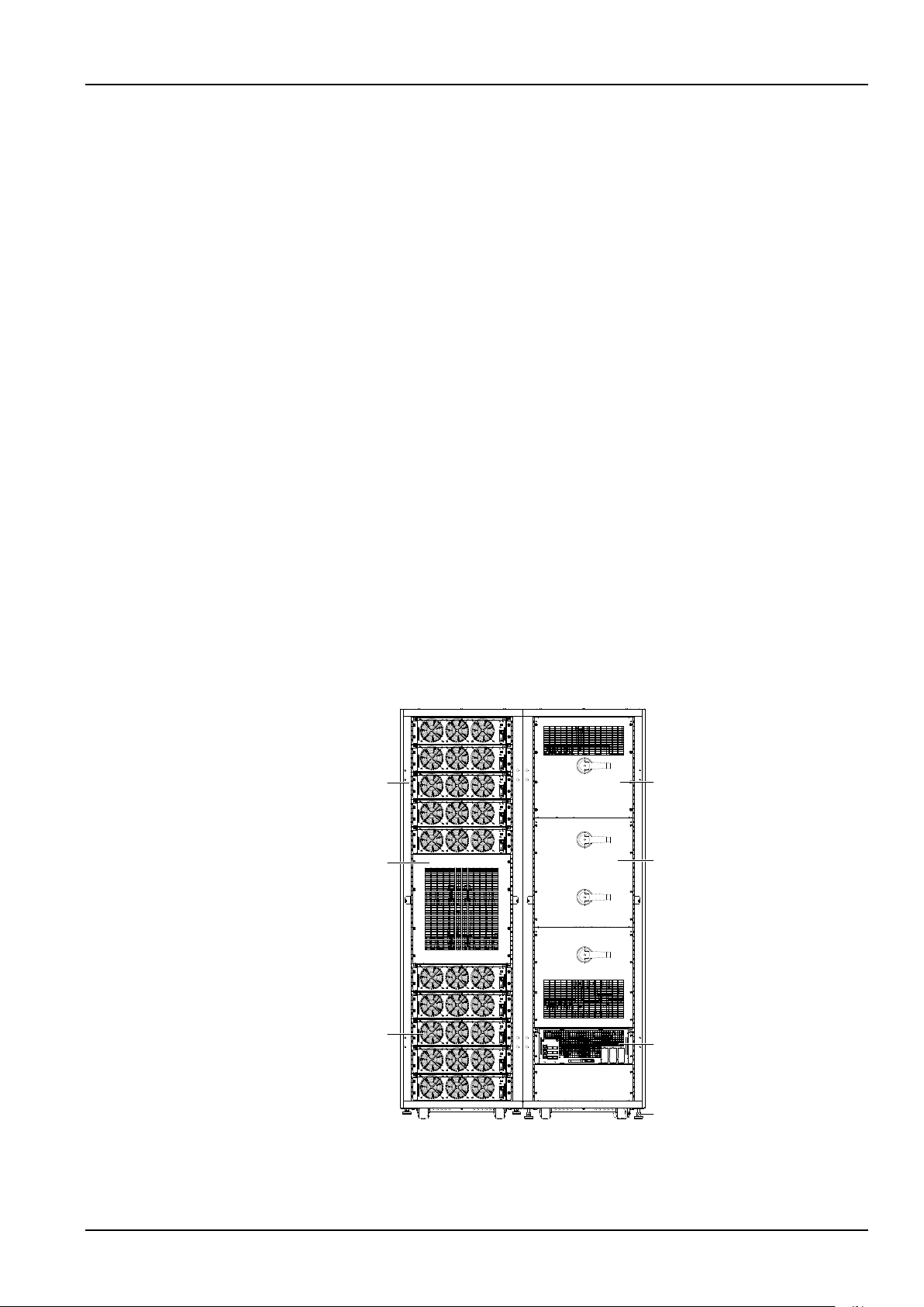
Main power cabinet
Cover
Power module
Switch cabinet
Cover
Bypass module
Adjustable foot
battery management and battery protection of the Liebert APM 300 UPS (UPS for short).
1.1 Features
The UPS is connected between a critical load (e.g. a computer) and mains power to provide high quality power
for the loads. The UPS has the following advantages:
Increase power quality
The UPS protects its output against the input power change through the internal voltage and frequency
controller.
Improve noise rejection
Due to the application of AC-DC-AC conversion mode, the noise in the input power is effectively filtered, and
the load gets clean power supply.
Provide mains failure protection
If the input power fails, the UPS will work in battery mode, and the power supply to the loads will not be
interrupted.
Chapter 1 Overview 1
Chapter 1 Overview
1.2 Composition
The UPS consists of a main power cabinet and a switch cabinet. The cabinets use steel framework structure
enclosed by removable panels, with the top panels and side panels fixed by screws. The UPS structure is shown
in Figure 1-1. The UPS component configuration is provided in Table 1-1.
Figure 1-1 UPS structure
APM 300 Integrated UPS Single Module And Parallel System User Manual
Page 15
2 Chapter 1 Overview
Component
Quantity (pcs)
Remark
Main power cabinet
1
Standard component
Switch cabinet
1
Standard component
Bypass module
1
Standard component
Power module
1
~
10
Mandatory option. Installed at site
Input
Maintenance bypass switch
Bypass input switch
Rectifier input switch
Bypass input
Mains input
Battery charger
Output switch
Automatic inverter s witch
Inverter
Rectifier
Static switch
Maintenance bypass
UPS output
Battery
Output
Input
Output
Bypass input
Mains input
Rectifier input switch
Rectifier
Maintenance bypass switch
Bypass input switch
Battery
Battery charger
Inverter
Static switch
Automatic inverter switch
Maintenance bypass
Output switch
UPS output
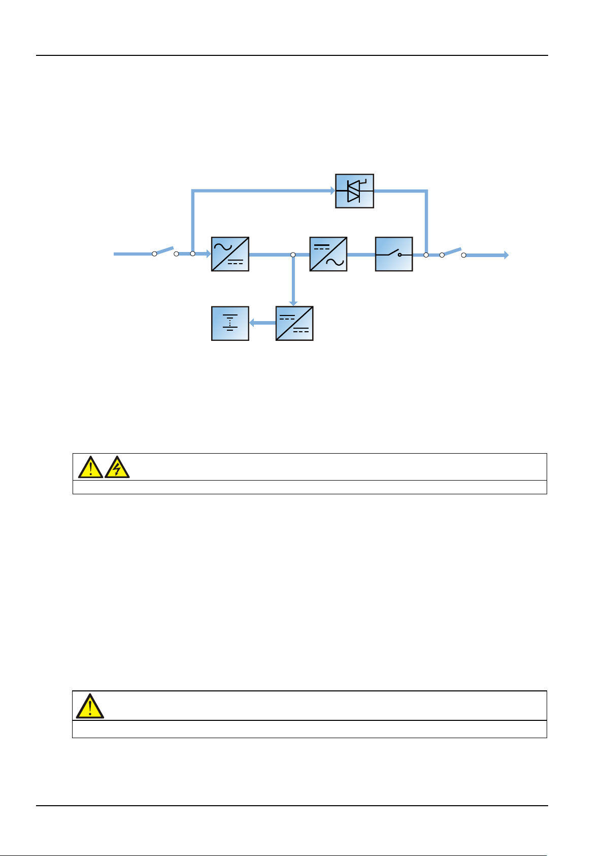
1.3 Design Concept
1.3.1 System Design
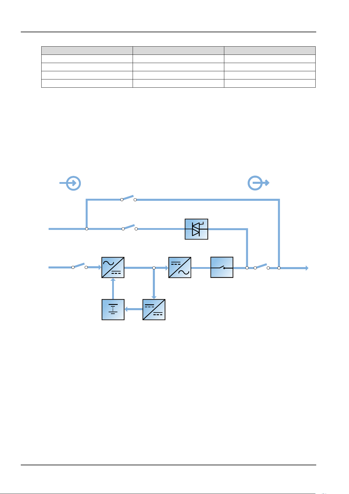
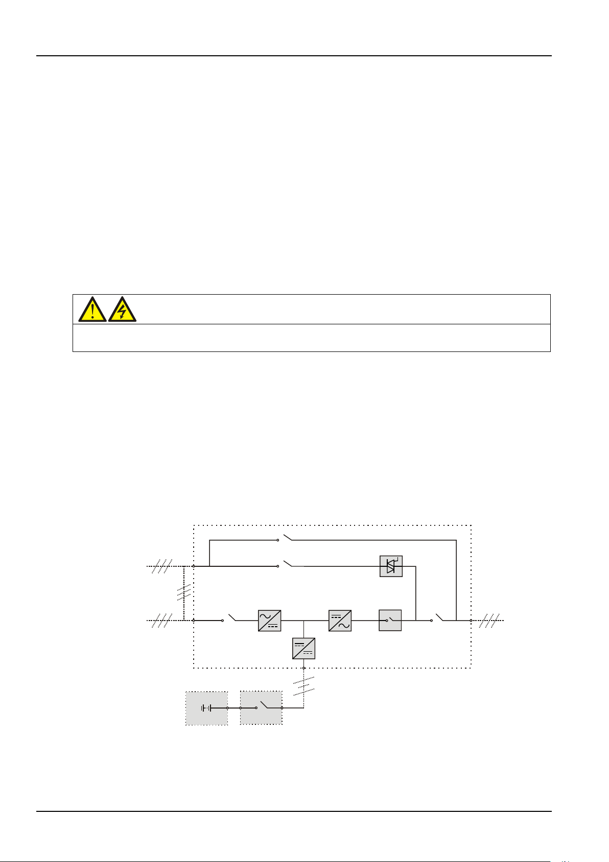
As shown in Figure 1-2, the AC mains source is converted by the rectifier into DC power. The inverter converts
that DC power from the rectifier or the DC power from the battery into AC power, and provides the AC power
for the load. The battery powers the load through the inverter in the event of a power failure. When the
inverter is faulty or turned off, the mains source can also power the load through the static bypass.
Tabl e 1-1 UPS component configuration
If UPS maintenance or repair is necessary, the load can be transferred to the maintenance bypass without
power interruption.
1.3.2 Bypass
The circuit block labeled static switch in Figure 1-2 contains an electronically controlled switching circuit that
enables the load to be connected to either the inverter output or to a bypass power source through the static
bypass line. During normal system operation, the load is connected to the inverters; but in the event of a UPS
overload or inverter failure, the load is automatically transferred to the static bypass line.
During normal operating conditions, the inverter output and bypass supply must be fully synchronized so as to
achieve a clean (no-break) load transfer between the inverter output and static bypass line. The
synchronization between the inverter output and static bypass is achieved through the inverter control
electronics, which make the inverter frequency track that of the static bypass supply, provided that the bypass
remains within an acceptable frequency window.
Figure 1-2 System schematic diagram
APM 300 Integrated UPS Single Module And Parallel System User Manual
Page 16

A manually controlled, maintenance bypass supply is incorporated into the UPS design. It enables the critical
Note
When the UPS is operating in bypass mode or on maintenance bypass, the connected equipment is not protected from
load to be powered from the maintenance bypass supply while the UPS is shut down for routine maintenance
and repair.
power failures or surges and sags.
1.3.3 System Control Principle
Normal operation
Normal mode: It means that the UPS has normal input mains, the rectifier and inverter operate normally, the
load is supplied by the inverter, and the battery is in stable floating charge state.
(Pa ral l el Sys tem)
Note: As each UPS module outputs are connected in parallel, the system checks that the
inverter control circuits are perfectly synchronized with one another and with the bypass in terms of both
frequency and phase, and that they have the same output voltages. Current supplied to the load is
automatically divided among UPSs. A warning message appears while synchronization is in progress.
Mains abnormal
Chapter 1 Overview 3
When the mains fails or is abnormal, the rectifier will stop working automatically, and the system will transfer
to battery output (through inverter). The length of the operation time in battery mode depends on the load
and the battery capacity. During this period, if the battery voltage falls to the EOD voltage and the mains still
has not been recovered, the inverter will stop working automatically, and the UPS operator control and display
panel will display corresponding alarm messages.
Mains recovery
When the mains resumes normal within allowable time, the rectifier will start automatically (at this time its
output power will increase gradually) and supply the load and charge the battery again. Therefore, the power
supply to the load will not be interrupted.
Battery disconnection
If the battery system is taken out of service for maintenance, it is disconnected from the rectifier/charger and
inverters by means of a battery switch. The UPS shall continue to function and meet all of the specified
steady-state performance criteria, except for the power outage back-up time capability.
UPS module failure
In case of inverter failure, automatic inverter switch failure, output fuse blowout and bypass STS failure, the
load will automatically transfer to the bypass, and the output power supply will not be interrupted. In this
situation, please contact the local customer service center of Emerson Network Power Co., Ltd for technical
support.
(Pa ral l el Sys tem)
In the event of a fault in a UPS module, it will automatically exit from the parallel system. If
the system is still capable of providing the required load, the remaining modules will continue to supply the
load with no interruption. If the remaining modules are no longer capable of fulfilling power requirements, the
load will automatically transfer to the bypass.
Overload
If the inverter is overloaded or the inverter current remains outside the specifications (refer to Table 11-6)
longer than the specified time, the load will automatically transfer to the bypass without power interruption. If
both the overload and the current are reduced to a level within the specified range, then the load will be
transferred back to the inverter. In case of output short circuit, the load will be transferred to the bypass, and
APM 300 Integrated UPS Single Module And Parallel System User Manual
Page 17
4 Chapter 1 Overview
Warning
The internal maintenance bypass must NOT be used when the UPS system is comprised of more than two UPS modules
Bypass input
Shorting copper bar
of common input
configuration
Mains input
Rectifier input
switch Q1
Rectifier Inverter
Automatic
inverter switch
Output
switch Q5 UPS Output
Static switch
Maintenance switch Q3
Battery
charger
BCB
Battery
Bypass input switch Q2
Maintenance bypass switch Q3
the inverter will shut down. Five minutes later, the inverter will start up automatically. If the short circuit is
removed at this point, the load will be transferred back to the inverter. The transfer is determined first of all by
the features of the protective device of the system.
In the above two situations, the UPS operator control and display panel will display alarm messages.
(Pa ral l el Sys tem)
The control logic system constantly monitors load requirements and controls the power
supplied by the two UPS modules. In the event that an overload condition is sustained for greater than a preset
time, the load will transfer to the bypass, when the number of active modules is unable to satisfy load
requirements. The load returns to the inverter if the power is reduced to a value that can be sustained by the
number of active modules in the system.
Maintenance bypass
The UPS has a second bypass circuit, i.e. maintenance bypass, which provides a safe working environment for
the engineers to provide regular maintenance or repair to the UPS system and at the same time provide
unregulated mains supply to the loads. The maintenance bypass can be manually selected through the
maintenance bypass switch, and it can be disconnected by turning the switch to OFF.
in parallel.
1.3.4 UPS Power Supply Switch Configuration
Figure 1-3 describes the block diagram of the UPS module. The UPS has split bypass configuration (that is, the
bypass adopts independent mains input) and common source configuration. In split bypass configuration,
the static bypass and maintenance bypass share the same independent bypass power supply. Where a
separate power source is not available, the input supply connections of the bypass input switch (Q2) and
rectifier input switch (Q1) would be linked together (linked before delivery) to make the bypass input and
rectifier input use mains power of the same route.
During the normal operation of the UPS, except for the maintenance bypass switch Q3, other switches shall be
closed.
APM 300 Integrated UPS Single Module And Parallel System User Manual
Figure 1-3 UPS power supply switch configuration
Page 18
1.3.5 Battery Circuit Breaker (BCB)
Qin UPS 1
Qin UPS 2
Qout UPS 1
Qout UPS 2
UPS 1 output UPS 2 output
L1, L2, L3L1, L2, L3
NN
Supplied by others
Input mains supply
L1, L2, L3, N
Charger
Rectifier
STS
Inverter
Input mains supply
L1, L2, L3, N
Charger
Rectifier
Inverter
STS
UPS 2 output distribution
unit 0~2 pcs
L1, L2, L3, N L1, L2, L3, N
UPS 1 output distribution
unit 0~2 pcs
UPS 1 output distribution UPS 2 output distribution
The external battery shall be connected to the UPS through the BCB. The BCB box is an option, which shall be
installed near the battery. The BCB is closed manually or electrically. The BCB has undervoltage tripping coil.
Upon the battery undervoltage, the UPS control circuit will send a signal to the coil to trip the BCB. It also has a
magnetic trip facility for overload protection.
1.4 Parallel System
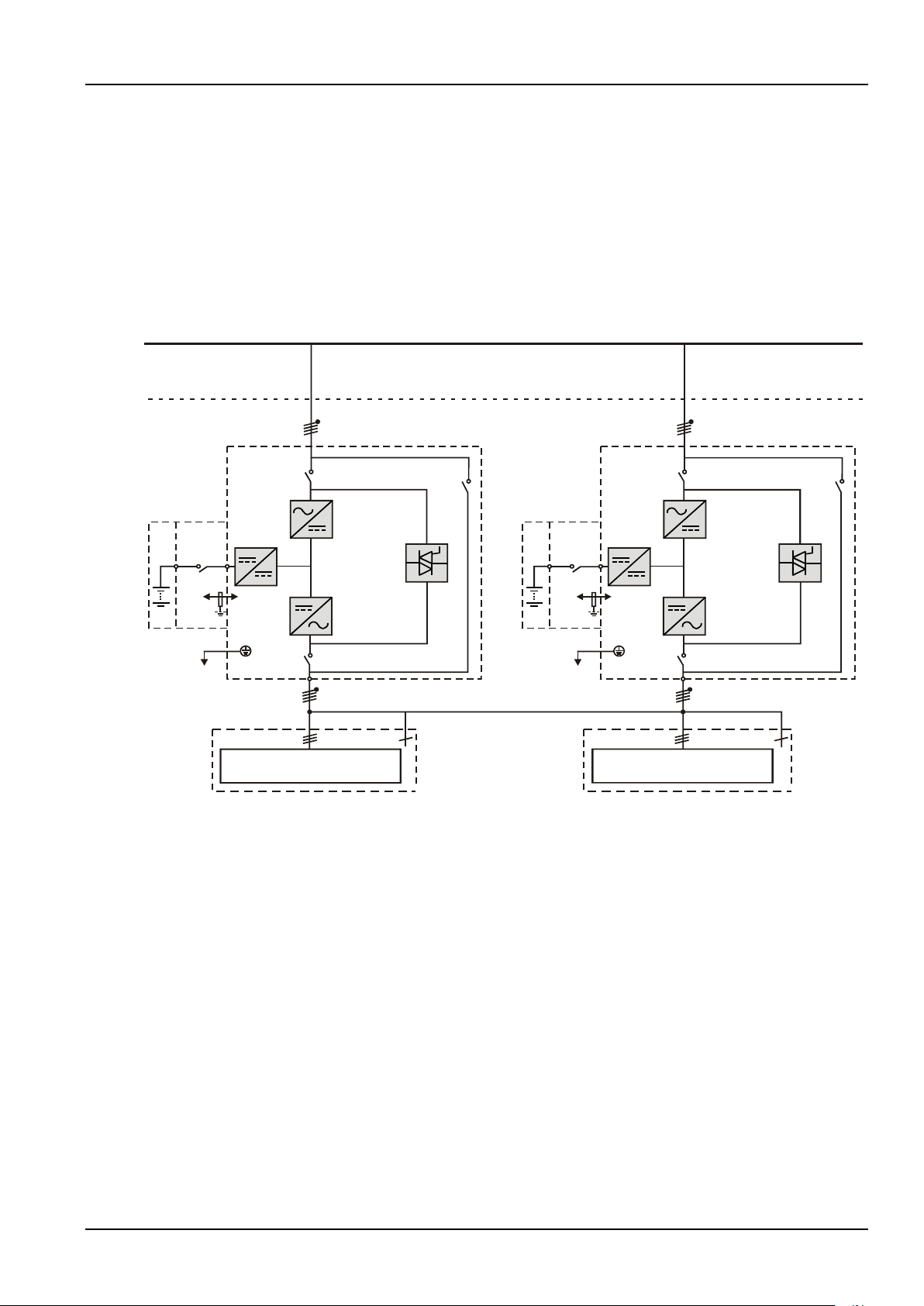
As shown in Figure 1-4, two UPS modules can be parallel-connected to form a parallel system to increase the
system capacity or reliability, or both. The load is equally shared between the paralleled UPSs.
Chapter 1 Overview 5
Figure 1-4 Parallel system
1.4.1 Parallel System Features
1. The hardware and software of parallel system are completely the same as those of single UPS module. The
parallel configuration is achieved through settings in configuration software. The parameter settings of each
UPS module in parallel system should be the same.
2. Parallel control cables are connected in a ring, providing both system reliability and redundancy. Dual bus
control cables are connected between any two UPS modules of each bus. The intelligent parallel logic provides
the user with maximum flexibility. For example, shutting down or starting up UPS modules in a parallel system
can be done in any sequence. Transfers between normal and bypass modes of operation are synchronized and
self-recoverable, for example, following overloads and their clearance.
3. The total load of the parallel system can be queried from each UPS module's LCD.
APM 300 Integrated UPS Single Module And Parallel System User Manual
Page 19
6 Chapter 1 Overview
Rectifier input switch
Mains input
Battery charger
Output switch
Inverter
Rectifier
UPS output
Battery
Automatic inverter s witch
Mains input
Rectifier input switch
Rectifier
Battery Battery charger
Inverter
Automatic inverter switch
Output switch
UPS output
1.4.2 Parallel System Requirements
A UPS system consisting of two paralleled UPS modules behave as if it were one large UPS with the advantage
of presenting higher reliability. To ensure that all modules are equally used and to comply with relevant wiring
rules, the following requirements apply:
1. All UPS modules must be of the same rating and must be connected to the same source.
2. Any RCD, if installed, must be of an appropriate setting and located upstream of the common neutral
bonding point. Alternatively, the device must monitor the protective earth current of the system. Refer to
Warning: high leakage current before Contents.
3. The outputs of the two UPS modules must be connected to a common output bus.
1.5 Operation Mode
The UPS is an on-line, double-conversion, reverse-transfer UPS that permits operation in these modes:
Normal mode
Battery mode
Automatic restart mode
Bypass mode
Maintenance mode (manual bypass)
ECO mode
Parallel and redundancy mode
Dormancy mode
Common battery mode
Frequency converter mode
Dual bus (LBS) system mode
Normal mode
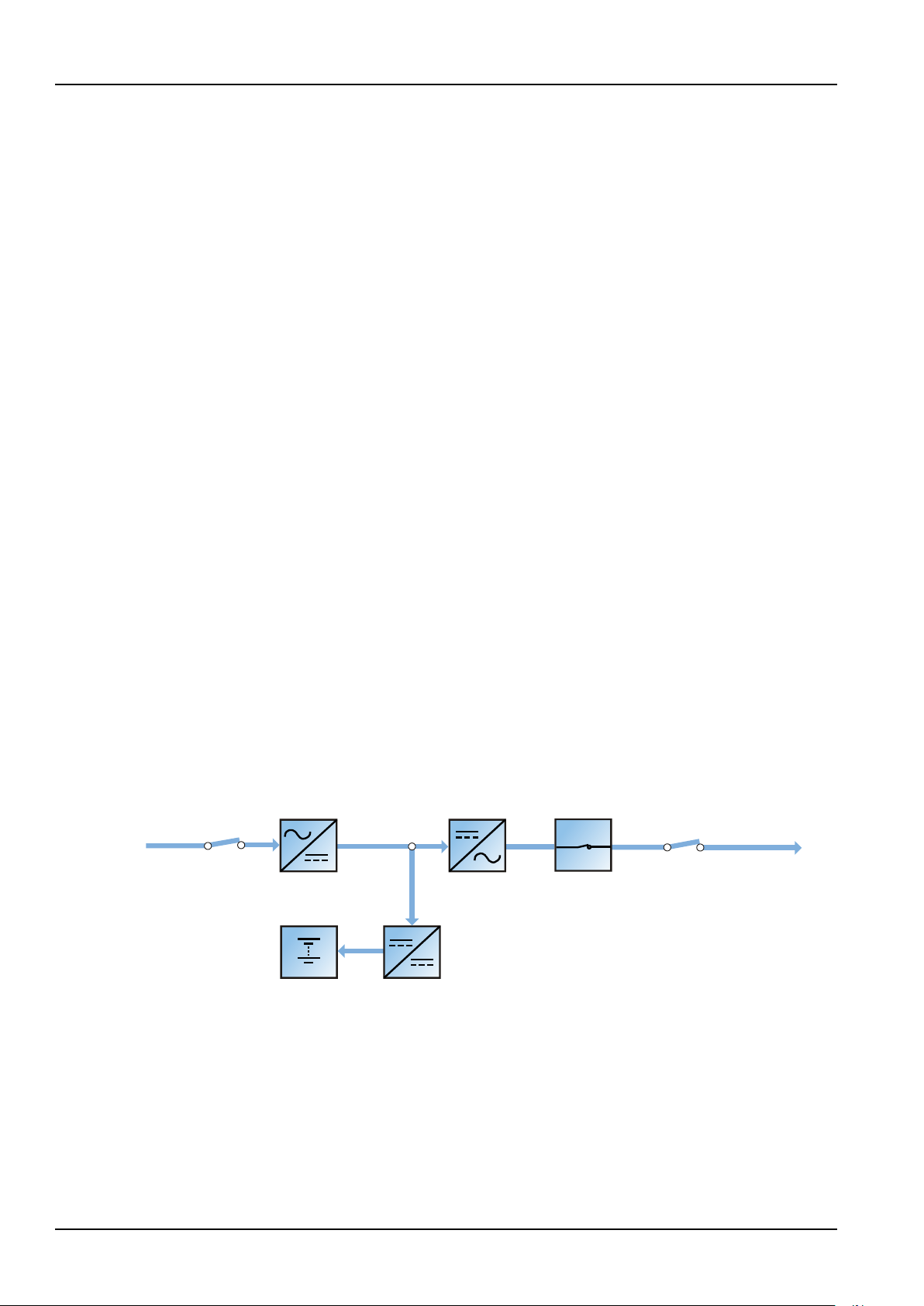
As shown in Figure 1-5, the UPS rectifiers derive power from the AC mains input source and supply DC power
to the inverters, which continuously supply the AC load. Simultaneously, the charger, which derives power
from the rectifiers, float or boost charges the associated backup battery of the UPS.
Figure 1-5 Schematic diagram of normal mode
Battery mode
As shown in Figure 1-6, the UPS is operating in battery mode when the battery is supplying backup power to
the load through the inverters. Upon mains failure, the UPS automatically transfers to battery mode without
power interruption to the load. Upon restoration of the AC mains, the UPS automatically transfers back to
normal mode without the necessity of user intervention, without power interruption to the load.
APM 300 Integrated UPS Single Module And Parallel System User Manual
Page 20
Chapter 1 Overview 7
Output switch
Inverter
Rectifier
UPS output
Battery
Automatic inverter s witch
Rectifier Inverter
Automatic inverter switch
Output switch
UPS output
Battery
Bypass input switch
Bypass input
Static switch
Output switch
UPS output
Bypass input
Bypass input switch
Static switch
Output switch
UPS output
Maintenance bypass switch
Bypass input
Maintenance bypass
UPS output
Bypass input
Maintenance bypass switch
Maintenance bypass
UPS output
Warning: risk after load transfer to maintenance bypass
After the UPS is transferred to maintenance bypass, the power modules and bypass module are inoperative and the LCD
input SPD shows that the UPS has mains input, but the output terminals
Figure 1-6 Schematic diagram of battery mode
Note: Battery start function is available for switching the UPS on into Battery (charged) mode directly during
mains failure. Thus, the battery power can be used independently to increase the UPS utility.
Automatic restart mode
The battery becomes exhausted following an extended AC mains failure. The inverters shut down when the
battery reaches the EOD voltage. The UPS can be programmed to automatic restart after EOD after a set
variable delay time. This mode and any delay time are programmed by the commissioning engineer.
During the delay time before automatic restart, the UPS charges the battery so as to avoid power interruption
to load in case of a following power failure.
In case the UPS is not programmed to automatic restart, you can use the FAULT CLEAR key to manually start
the UPS.
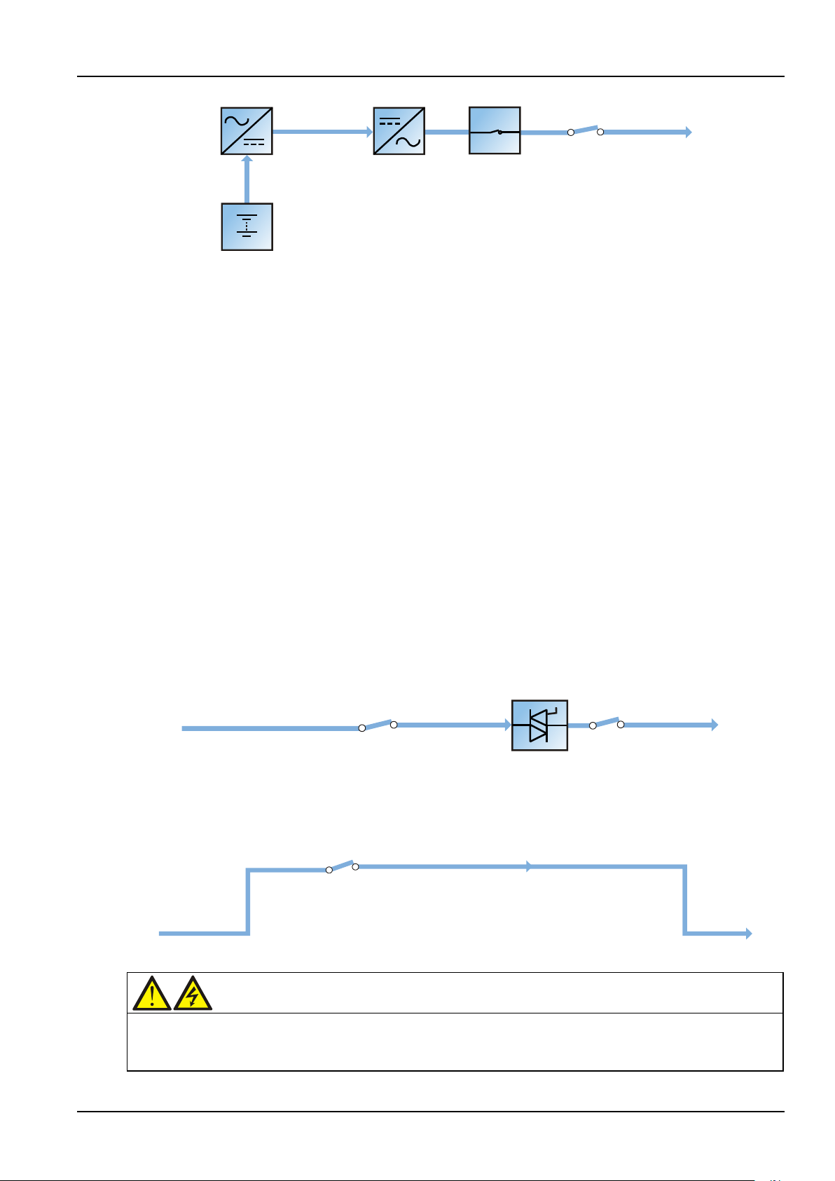
Bypass mode
As shown in Figure 1-7, during normal mode operation, if the inverters fail, are overloaded or turned off, the
static switch will perform a transfer of the load from the inverters to the bypass source, with no interruption in
power to the load. Should the inverters be asynchronous with the bypass, the static switch will perform a
transfer of the load from the inverters to the bypass, with interruption in power to the load. This is to avoid
paralleling of unsynchronized AC sources. This interruption is programmable but typically set to be less than
3/4 of an electrical cycle, for example, less than 15ms (50Hz) or less than 12.5ms (60Hz).
Figure 1-7 Schematic diagram of bypass mode
Maintenance mode
As shown in Figure 1-8, if UPS maintenance or repaired is needed, you may use the manual maintenance
bypass switch to transfer the load to the maintenance bypass, with no interruption in power to the load.
Figure 1-8 Schematic diagram of maintenance mode
has no display, only the green indicator of the
corresponding to closed output distribution switches and the neutral bars are energized.
APM 300 Integrated UPS Single Module And Parallel System User Manual
Page 21
8 Chapter 1 Overview
市电输入
整流器
逆变器
电池
电池充电器
UPS输出
输入开关
逆变自动开关
Mains input
Input switch
Rectifier Inverter
Automatic
inverter switch
Output switch
Static switch
Charger
Battery
UPS output
Static switch
Rectifier
Inverter
Automatic
inverter switch
UPS output
Output switch
ChargerBattery
Mains input
Input switch
Warning
In ECO mode the load is not protected against mains distortion.
Note
ECO mode
As shown in Figure 1-9, in ECO mode, except for the maintenance bypass switch, all power switches and the
BCB are closed, the system prefers to put the load on the bypass mains to save energy. When the bypass
frequency and voltage are in normal range (settable), the load is supplied by the bypass, with the inverter on
standby. When the bypass frequency and voltage are beyond the normal range, the system will transfer to the
inverter. In ECO mode, the battery is normally charged by the charger.
Figure 1-9 Schematic diagram of ECO mode
The ECO mode configuration requires a different setup in the default menu configuration through the
operator control and display panel.
Operating procedures in ECO mode are the same as those described in Chapter 5 Operating Instructions,
except that the load is normally on the bypass mains, the Inverter LED is normally off, and the corresponding
alarm message 'Bypass mode' will appear on the LCD.
Parallel redundancy mode
For higher capacity or higher reliability or both, the outputs of two UPS modules can be programmed for
direct paralleling while a built-in parallel controller in each UPS ensures automatic load sharing.
Dormancy mode
Dormancy mode is designed to maximize the number of the dormant power modules while ensuring load
power, which brings the system efficiency to the greatest extent. The dormancy mode is configured by the
commissioning engineer through the background software. This mode has the following restrictions on the
power module addresses: When there are five power modules, the power module addresses should be 1, 2, 3,
4 and 5 in turn; when there are four power modules, the power module address should be 1, 2, 3 and 4 in turn;
when there are three power modules, the power module addresses should be 1, 2 and 3 in turn; when there
are two power modules, the power module addresses should be 1 and 2 in turn.
In dormancy mode, sudden load change should be avoided, which may cause UPS transfer to bypass mode.
APM 300 Integrated UPS Single Module And Parallel System User Manual
Page 22

Chapter 1 Overview 9
Note
Common battery mode
Common battery function means that in UPS paralleling, the UPS modules can share a battery string to save
cost and space and improve efficiency.
Batteries of different manufacturers, models or used time cannot be used together.
Frequency converter mode
The UPS can be programmed into frequency converter mode for either 50Hz or 60Hz stable output frequency.
The input frequency may vary from 40Hz to 70Hz. In this mode, it is required to open the maintenance bypass
switch to disable the static bypass operation, and the battery becomes optional depending on any
requirement to operate in battery mode.
Dual bus (LBS) system mode
A dual bus system consists of two independent UPS single unit systems. The dual bus system has high
reliability and is suitable for load with multiple inputs. For single input load, an optional STS can be installed to
power the load. For the operation principle diagram of the dual bus system mode, see Figure 7-5.
1.6 Battery Management (Set By Commissioning Engineer)
1.6.1 Normal Function
1. Constant current boost charge.
The charge current can be set.
2. Constant voltage boost charge.
The boost charge voltage can be set as required by the type of battery.
For VRLA batteries, the maximum boost charge voltage should not exceed 2.4V/cell.
3. Float charge.
The float charge voltage can be set as required by the type of battery.
For VRLA batteries, the float charge voltage should be between 2.2V/cell and 2.3V/cell.
4. Float charge temperature compensation (optional).
The temperature compensation coefficient can be set as required by the type of battery.
5. EOD protection.
When the battery voltage drops to the EOD voltage, the battery converter shuts down automatically and the
battery is isolated to avoid further battery discharge. The EOD voltage is settable from 1.6V/cell to 1.75V/cell
(VRLA) or 0.9V/cell to 1.1V/cell (NiCd).
6. Battery low pre-warning time.
The battery low pre-warning time is adjustable between 3min and 60min. The default setting is 5min.
1.6.2 Advanced Function
The UPS provides battery maintenance test function. Battery maintenance test is also called as battery
self-test. At periodic intervals, 20% of the rated capacity of the battery will be discharged automatically, and
the actual load must exceed 20% of the UPS nominal capacity. If the load is less than 20%, the automatic
discharge cannot be executed. The periodic interval can be set from 30 to 360 days. The battery self-test can
be disabled.
Conditions: battery at float charge for at least 5h, load equal to 20%
~ 80% of rated UPS capacity.
APM 300 Integrated UPS Single Module And Parallel System User Manual
Page 23

10 Chapter 1 Overview
Trigger: manually through the command of Battery Maintenance Test on LCD or automatically.
Interval: 30 days ~
360 days (default setting: 60 days).
1.6.3 Battery Temperature Compensation
The UPS system has battery charge temperature compensation function. When the ambient temperature is
increased, the DC bus voltage (which charges the battery) will be reduced correspondingly to provide optimal
charging voltage for the battery, thus prolonging the battery service life time.
This function must be used together with the Emerson battery temperature detection device (a standard
option).
1.7 Battery Protection (Set By Commissioning Engineer)
Battery low pre-warning
The battery low pre-warning occurs before the EOD. After this pre-warning, the battery should have the
capacity for three remaining minutes discharging with full load. The time can be configured from 3min to
60min.
EOD protection
When the battery voltage drops to the EOD voltage, the battery converter shuts down. The EOD voltage is
adjustable from 1.6V/cell to 1.75V/cell (VRLA) or 0.9V/cell to 1.1V/cell (NiCd).
BCB open alarm
This warning occurs when the BCB opens. The battery is connected to the UPS through the BCB, which is
manually closed and electronically tripped by the UPS control circuits.
APM 300 Integrated UPS Single Module And Parallel System User Manual
Page 24
This chapter introduces the installation of the UPS, including the notes, preliminary check, environmental
Warning: professional installation required
1. Do not apply electrical power to the UPS before being authorised to do so by the commissioning engineer.
Note: 3-phase, 5-wire input supply required
The standard UPS is suitable for connection to 3-phase, 5-wire (A, B, C, N, PE) TN and TT AC power distribution systems
Warning: battery danger
Take special care when installing batteries. When connecting batteries, the battery terminal voltage will reach 320Vdc,
considerations, mechanical considerations, and installation drawings.
2.1 Notes
This chapter describes the requirements that must be taken into account when installing the UPS equipment.
Because each site has its particular characteristics, this chapter does not provide the detailed installation steps,
it only acts as a guide for the general procedures and practices that should be observed by the installing
engineer, so that they can properly handle the specific situation of the site.
2. The UPS shall be installed by a qualified engineer in accordance with the information contained in this manual.
Chapter 2 Mechanical Installation 11
Chapter 2 Mechanical Installation
(IEC60364-3).
which is fatal to human being.
1. Please wear safety glasses to protect the eyes from being damaged by arc.
2. Remove all the metal items, including finger rings, watch, etc.
3. Use tools with insulated handle.
4. Wear insulating gloves.
5. If the battery has electrolyte leakage or the battery is damaged, it must be replaced. Place the battery into the
container that can withstand sulfuric acid and dispose of it according to the local regulations.
6. If the skin contacts the electrolyte, flush it with water immediately.
2.2 Preliminary Check
Before installing the UPS, carry out the following preliminary checks:
1. Visually examine the UPS for shipping damage, both internally and externally. Report any damage to the
shipper immediately.
2. Verify that the correct UPS is being installed. The UPS has an identification tag on the back of the front door
reporting the model, capacity and parameters of the UPS.
2.3 Environmental Requirements
2.3.1 UPS Location
For optimal design life, the place chosen must offer:
Easy connection
APM 300 Integrated UPS Single Module And Parallel System User Manual
Page 25
12 Chapter 2 Mechanical Installation
Note
The UPS is suitable for mounting on concrete or other non-combustible surface only.
Warning
During storage, periodically charge the battery according to the battery manufacturer instructions. In the charge
Enough space to easily work on the UPS
Sufficient air exchange to dispel heat produced by UPS
Protection against atmospheric agents
Protection against excessive humidity and high heat sources
Protection against dust
Compliance with the current fire prevention requirements
Operating environment temperature between 20°C and 25°C. The batteries are at maximum efficiency
in this temperature range
The UPS is intended for indoor installation and should be located in an environment with clean air and with
adequate ventilation to keep the ambient temperature within the specified operating range.
The UPS is air-cooled with the aid of internal fans. Cold air enters the UPS through the ventilation grilles in the
front of the cabinet and hot air is released through the grilles on the back. Do not cover the ventilation
openings.
If necessary, install a system of room extractor fans to avoid room temperature build-up. Optional air filters
are available if the UPS is to operate in a dusty environment.
2.3.2 Battery Location
The batteries will generate small amount of hydrogen and oxygen at the end of battery charge. Therefore,
make sure that the new air ventilation amount in the battery room meets the EN50272-2001 requirement.
Batteries should be mounted in an environment where the temperature is consistent and even over the whole
battery. Temperature is a major factor in determining the battery life and capacity. Typical battery
manufacturer performance data are quoted for an operating temperature of 20
reduce the battery life while operation below 20
battery operating temperature increases from 20°C to 30°C, the battery life will be reduced by 50%; provided
that the average battery operating temperature is above 40
exponential multiple. In a normal installation the battery temperature is maintained between 15
Keep batteries away from main heat sources and main air inlets.
The UPS uses external batteries, a battery protection device (for example, fuses or circuit breakers) must be
mounted as close as possible to the batteries themselves, and connected using the most direct route possible.
2.3.3 Storage
Should the UPS not be installed immediately, it must be stored in a room for protection against excessive
humidity and heat sources. The batteries should be stored in a dry, cool environment with adequate
ventilation, at temperature ranging from 20
°C. Operating above 20°C will
°C will reduce the battery capacity. Provided that the average
°C, the battery life will be reduced by an
°C and 25°C.
°C to 25°C at best.
process, temporarily connect the UPS to the mains for the time required for recharging the battery to activate the
battery.
APM 300 Integrated UPS Single Module And Parallel System User Manual
Page 26
2.4 Positioning
Warning
1. Ensure that any equipment used to move the UPS has sufficient lifting capacity. For the UPS weight, refer to
2. The UPS is fitted with casters. Take care to prevent the cabinet from moving when unbolting the cabinet from the
et can be pushed forward or backward only. Pushing it sideward is not allowed. When pushing the cabinet,
Important
Fixing the UPS to the installation surface through the anchor holes on the UPS base is mandatory.
2.4.1 Moving The Cabinet
Table 11-3.
shipping pallet. Ensure that adequate personnel and lifting aids are available when removing the shipping pallet.
3. The UPS casters are just strong enough for cabinet moving on flat surface. They may not function well when you
move the cabinet on uneven surface.
4. The cabin
take care not to overturn it as the gravity center is high.
The UPS can be moved by a forklift or similar equipment. It can also be moved short distances by its casters.
2.4.2 Clearances
The UPS has no ventilation grilles at either side, therefore, no clearance is required at either side.
The component layout of the UPS supports front access and rear access in UPS service, diagnosis and repair. To
enable routine tightening of power terminations within the UPS, in addition to meeting any local regulations,
it is recommended to provide adequate clearance in the front and at the back of the cabinet for unimpeded
passage of personnel with the front and back doors fully opened.
Chapter 2 Mechanical Installation 13
2.4.3 Cable Entry
The UPS uses top cable entry and bottom cable entry, with cable entry holes provided both at the bottom and
on the top of the UPS.
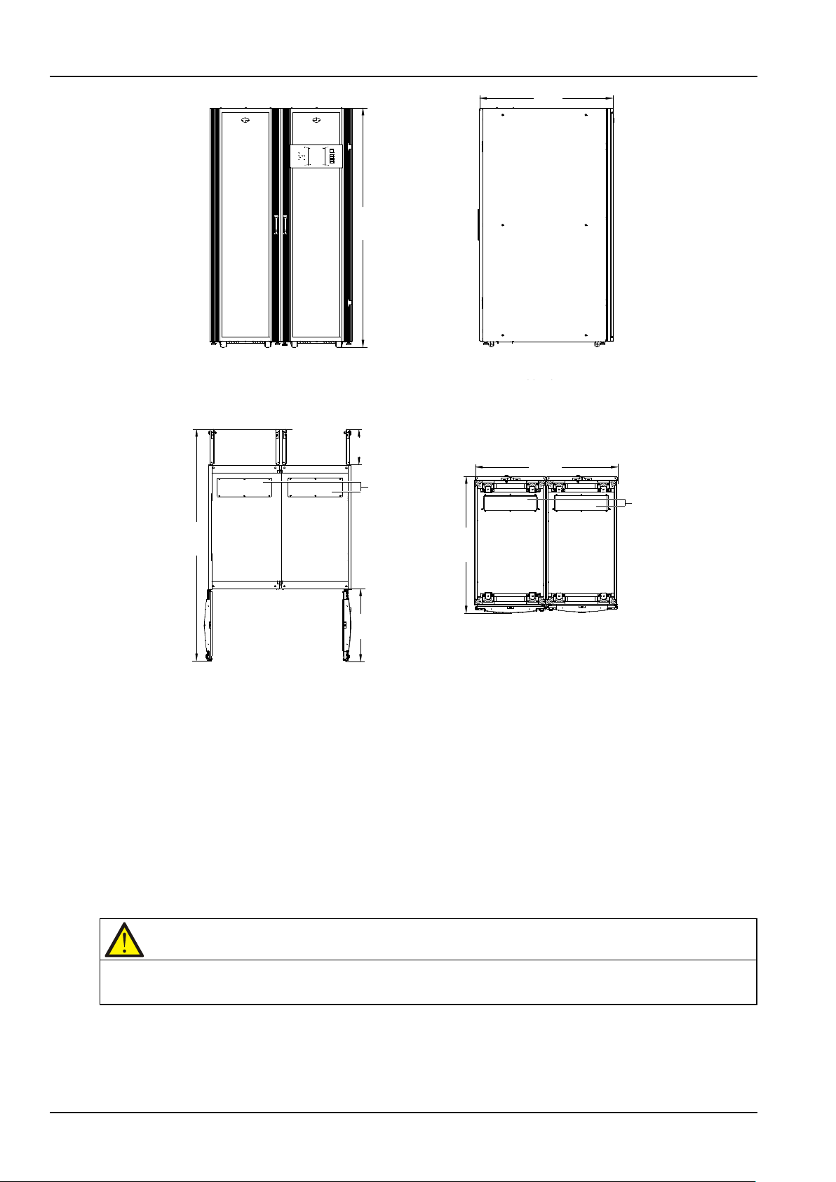
2.4.4 Final Positioning And Fixing
After final positioning, fix the UPS directly on the installation surface through the anchor holes on the UPS
base. Figure 2-1 shows the UPS installation dimensions.
2.5 Mechanical Installation
2.5.1 Installation drawing
Refer to Figure 2-1 for the UPS installation dimensions.
APM 300 Integrated UPS Single Module And Parallel System User Manual
Page 27
14 Chapter 2 Mechanical Installation
2000
1100
Front view
Main power
cabinet
Switch cabinet
Side view
1100
1200
1930
300
600
Main power
cabinet
Switch
cabinet
Front door
Front view
(front door and back door open)
Main power
cabinet
Switch cabinet
Bottom view
Back door
Cover
Cover
2000
300
1930
600
1100
1200
1100
Front view Side view
Cover
Cover
Main power
cabinet
Switch
cabinet
Front door
(front door and back door open)
Main power
cabinet
Switch cabinet
Bottom view
Front view
Back door
Main power
cabinet
Switch cabinet
Note
Replace the cover at the front of the switch cabinet after connecting the parallel power cables. Refer to 3.1.8
Figure 2-1 UPS installation dimensions (unit: mm)
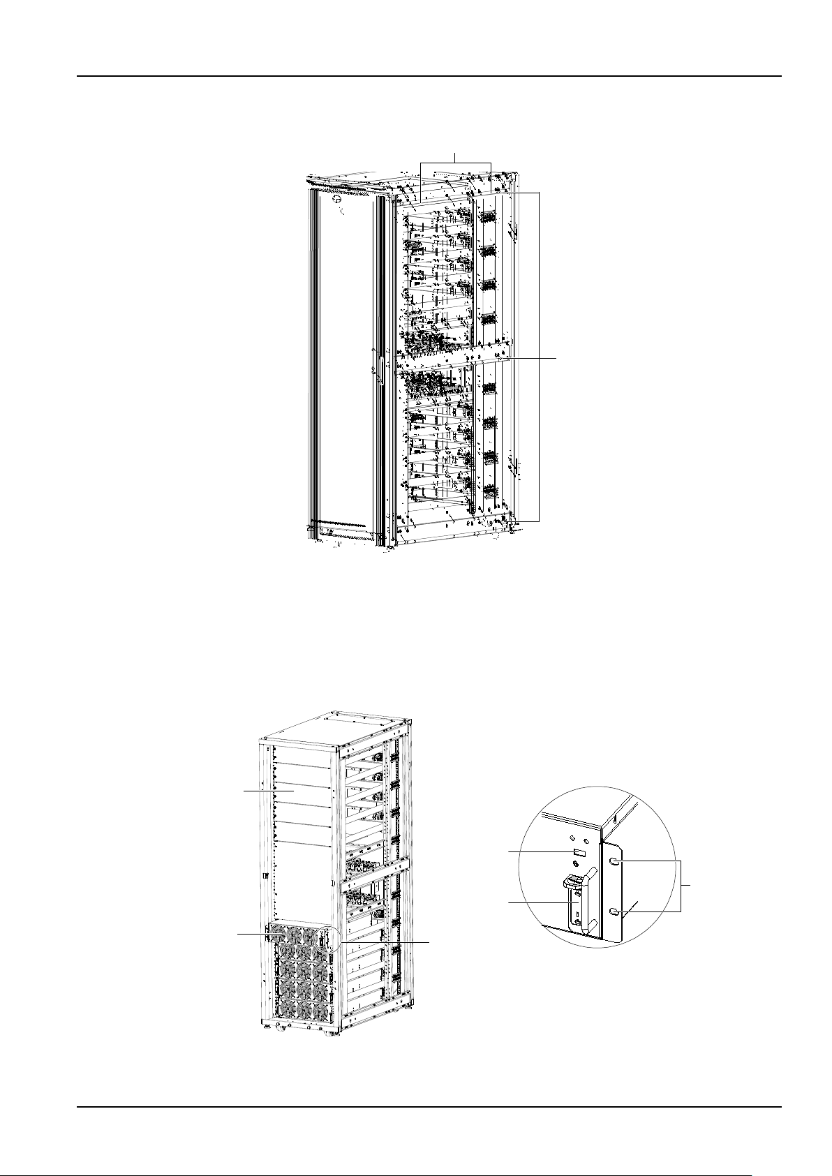
2.5.2 Mechanical Connection Between Cabinets
The UPS consists of a main power cabinet and a switch cabinet. The two cabinets are shipped separately and
should be connected mechanically at site. The connection procedures are as follows:
1. Place the main power cabinet and switch cabinet closely side by side, with the main power cabinet on the
left side and the switch cabinet on the right side, as shown in Figure 2-2.
2. Adjust the two cabinets to the same height and fix them securely in the position by adjusting the adjustable
feet (see Figure 1-1).
3. Open the front door of the switch cabinet and remove the cover (see Figure 2-2) at the front.
Connecting Power Cables.
4. Connect the cabinets with screws: There are two screw holes for cabinet connection (see Figure 2-2) in the
same positions of each beam (totally three beams) on the right side of the main power cabinet. In the
corresponding positions on the left side of the switch cabinet, there are also three beams; and in the same
APM 300 Integrated UPS Single Module And Parallel System User Manual
Page 28
Chapter 2 Mechanical Installation 15
Right side
Screw hole for cabinet connection
Beam
Right side
DIP switch
Ready switch
Fixing hole
A Amplified view
Dummy plate
Power module
A
positions of each beam, there are also two screw holes for cabinet connection. Use the accessory M8 × 20
screws to connect the two cabinets through these screws holes, and tighten the connections to 13N.m.
2.5.3 Installing Power Module
The installation positions of the power modules are shown in Figure 2-3. Install the power modules from
bottom to top to avoid cabinet tipping due to high gravity center.
Refer to Figure 2-3, and use the following procedures to install the power module:
Figure 2-2 Screw holes for cabinet connection on main power cabinet
Figure 2-3 Installing power module
APM 300 Integrated UPS Single Module And Parallel System User Manual
Page 29

16 Chapter 2 Mechanical Installation
DIP switch setting
Module address
1. Use the DIP switch on the front panel of the module to set the module address. The setting range is from 1
to 10. The module address should be exclusive. The setting method is shown in Table 2-1.
Table 2-1 DIP switch setting method
3
6
7
9
1
2
4
5
8
10
2. Place the ready switch on the front panel of the module to the up position (that is, in unready state).
3. Remove the dummy plate in the installation position of the module, insert the module in the installation
position, and push it into the cabinet.
4. Secure the module to the main power cabinet through the fixing holes on both sides of the front panel of
the module.
5. Place the ready switch to the down position (that is, in ready state).
APM 300 Integrated UPS Single Module And Parallel System User Manual
Page 30

Chapter 3 Electrical Installation
Warning: professional installation
1. Do not power on the UPS before the arrival of authorized service engineer.
UPS rated
power (kVA)
Rated current (A)
Input mains current
1,2
with full battery recharge
Total output current
2
at full load (36 cells)
Battery discharge
current at EOD
380V
400V
415V
380V
400V
415V
300
560
530
510
450
430
410
1050
270
514
477
459
405
387
369
945
240
448
424
408
360
344
328
840
210
392
371
357
315
301
287
735
180
336
318
306
270
258
246
630
150
280
265
255
225
215
205
525
120
224
212
204
180
172
164
420
90
168
159
153
135
129
123
315
60
112
106
102
90
86
82
210
30
56
53
51
45
43
41
105
This chapter introduces the electrical installation of the UPS, including the procedures or methods for power
cabling and control cabling, the distance from floor to connection point, and the connection of cabinets.
The UPS requires both power cabling and control cabling once it has been mechanically installed. All control
cables, whether shielded or not, should be run separately from the power cables.
2. The UPS cables must be routed by an authorized engineer in accordance with the information contained in this
chapter.
3.1 Power Cables
3.1.1 System Configuration
Chapter 3 Electrical Installation 17
The cable size of the system power cable shall meet the following requirements:
UPS input cables
The size of the UPS input cable differs with the UPS power ratings and input AC voltages, provided that it
meets the requirement of rated input current, including the rated battery charge current, see Table 3-1.
UPS bypass and output cables
The size of the UPS bypass and output cable differs with the UPS power rating and output AC voltages,
provided that it meets the requirement of rated output or bypass current, see Table 3-1.
Battery cables
Each UPS connects to its battery through two cables connecting to the positive pole and negative pole. The
cable size of the battery cable differs with the UPS power ratings, provided that it meets the battery discharge
current requirement when the battery discharges to near EOD voltage, see Table 3-1.
3.1.2 Maximum Steady State AC And DC Currents
Table 3-1 Maximum steady state AC and DC currents
APM 300 Integrated UPS Single Module And Parallel System User Manual
Page 31

18 Chapter 3 Electrical Installation
UPS connection point
Distance (mm)
Rectifier input
1444
Bypass input
1084
AC output
804
Battery power
842
Warning
Failure to follow adequate earthing procedures may result in EMI or hazards involving electric shock and fire.
Warning
Failure to follow adequate earthing procedures could result in electric shock hazard to personnel, or the risk of fire,
1. Rectifier and bypass input mains current.
2. Non-linear loads (switch mode power supplies) affect the design of the output and bypass neutral cables. The current
circulating in the neutral cable may exceed the nominal phase current. A typical value is 1.732 times the rated current.
3.1.3 Distance From Floor To UPS Connection Point
Table 3-2 provides the distances from the floor to the UPS connection points.
Table 3-2 Distance from floor to UPS connection point
3.1.4 Notes
The following are guidelines only and superseded by local regulations and codes of practice where applicable:
1. Earth cable: Follow the most direct route possible to connect the earth cable to the cabinet. Size the earth
cable by referring to IEC60950-1 Table 3B and following the local electrical regulations, and in accordance with
the AC supply fault rating, cable lengths and type of protection.
2. In battery cable selection, a maximum voltage drop of 4Vdc is permissible at the current ratings given in
Table 3-1. To minimize the formation of electromagnetic interference, do not form coils.
3. The connection terminals are shown in Figure 3-1 and Figure 3-2.
3.1.5 Power Cable Connecting Terminals
The rectifier input, bypass, output and battery power cables are connected to the corresponding busbars
situated of the UPS, as shown in Figure 3-1 to Figure 3-2.
3.1.6 Protection Ground
The protective earth cable is reliably connected to the PE input terminal (see Figure 3-2) via the fixing bolt.
All the cabinets and cable troughs shall be grounded according to the local regulations. The grounding wires
shall be tied up reliably to prevent the loosening of the grounding wire tightening screws when the grounding
wires are pulled.
should an earth fault occur.
3.1.7 External Protective Device
To ensure the safety, it is necessary to install external circuit breaker for the input and battery of the UPS.
Because of the difference of the specific installations, this section only provides general practical information
APM 300 Integrated UPS Single Module And Parallel System User Manual
Page 32

Chapter 3 Electrical Installation 19
Note
The UPS output neutral line is from the input neutral line. If the external block device blocks input neutral line, the
Warning
The power cables should be routed through cable tunnel or metallic cable trough to avoid being damaged under
for the installation engineer. The qualified installation engineer should have the knowledge of the local wiring
regulations on the equipment to be installed.
Rectifier and bypass input supply of the UPS
1. Overcurrent
Install suitable protective devices in the distribution of the incoming mains supply, considering the power
cable current-carrying capacity and overload capacity of the system (see Table 11-6, Table 11-7). Generally,
thermomagnetic circuit breaker with IEC60947-2 tripping curve C (normal) at 125% of the current listed in
Table 3-1 is recommended.
Split bypass: In case a split bypass is used, separate protective devices should be installed for the rectifier input
and bypass input in the incoming mains distribution panel.
The rated voltage of the external main/bypass overcurrent protective device should not be less than 415Vac,
and its AC breaking current should be more than 6kA, and it should be a 3P device for three phases.
output neutral line will be lost, and then the system risk may be caused.
2. Earth leakage
The residual earth current introduced by the RFI suppression filter inside the UPS is greater than 3.5mA and
less than 1000mA. It is recommended that the sensitivity of all differential devices be verified upstream of the
input distribution panel.
3. Battery
A battery protective device (for example, a fuse or a breaker) must be fitted to provide overcurrent protection
for the 4. The rated voltage of the overcurrent protective device of the external battery should be higher than
500Vdc, and its DC breaking current should be higher than 20kA.
4. UPS Output
The UPS output distribution shall be configured with a protective device. The protective device shall be
different from the input distribution protection switch and able to provide overload protection (refer to
Table 11-6).
3.1.8 Connecting Power Cables
For cable access mode of the UPS, refer to 2.4.3 Cable Entry.
mechanical stress and reduce EMI to the environment.
The procedures for connecting the parallel power cables are as follows:
1. Remove the cover at the front and the left side panel of the main power cabinet.
2. The parallel power cables have been connected in factory to the copper bars in the upper part and lower
part of the switch cabinet, as shown in Figure 3-1. Run the parallel power cables into the main power cabinet
by the cabling route shown in Figure 3-1 to the corresponding connection terminals.
3. According to the labels of the parallel power cables and those of the corresponding connection terminals of
the main power cabinet, use the accessor y M8 ×
25 screws and M8 nuts to connect the cables to the
connection terminals with the same labels correspondingly, and tighten the connections to 13N.m. Note that
each connection terminal should be connected to two cables.
APM 300 Integrated UPS Single Module And Parallel System User Manual
Page 33

20 Chapter 3 Electrical Installation
Main power cabinet
Switch cabinet
Main power cabinet
Run the parallel power cables from here
Cabling
route
A
Switch cabinet
Run the parallel power cables from here
mA-1 mB-1 mC-1 mN-1 o
A-1 oB-1 oC-1 oN-1
mA-2 mB-2 mC-2 mN-2 oA-2 oB-2 oC-2 oN-2
A Amplified view (connection terminals in main power cabinet)
Important
The operations described in this section must be performed by authorised personnel. If you have any questions, please
4. Use a multimeter to measure and confirm that the connections are correct and no inter-phase short circuit
exists.
5. Bind the parallel power cables.
6. Replace the cover and left side panel of the main power cabinet removed in step 1 and the cover at the front
of the switch cabinet removed in the procedures in 2.5.2 Mechanical Connection Between Cabinets.
Figure 3-1 Connecting parallel power cables
3.1.9 Connecting External Power Cables
contact the local customer service center of Emerson immediately.
Once the UPS has been finally positioned and secured, connect the power cables as described in the following
procedures.
1. Verify that the external input switch and all internal power switches of the UPS are open. Post warning signs
on these switches to prevent inadvertent operation.
2. Open the back doors of the main power cabinet and switch cabinet to reveal the connection terminals of
the power cables, including the rectifier input terminals, bypass input terminals, output terminals, battery
input terminals and PE terminals, as shown in Figure 3-2.
APM 300 Integrated UPS Single Module And Parallel System User Manual
Page 34

Chapter 3 Electrical Installation 21
Rectifier input term i nal
B
A amplified view
B amplified view
mA mB mC mN
bA
bB
bC
PE
Bypass input terminal
Output terminal
oA
oB
oC
oN
-
Battery input terminal
+
N
Switch cabinet Main power cabinet
A
B
Switch cabinet
Main power cabinet
Rectifier input terminal
mA mBmC mN
bA
bB
bC
PE
Bypass input terminal
oA
oB
oC
oN
Output terminal
Battery input terminal
N
+
-
A Amplified view
B Amplified view
Note
The earth cable and neutral cable must be connected in accordance with local and national codes of practice.
Common input connection
Split bypass connection
Warning
In split bypass configuration, remove the linking busbars between the bypass input and rectifier input. The rectifier
System output connection
Figure 3-2 Connection terminals of power cables (back view)
3. The UPS uses top cable entry and bottom cable entry. Remove the covers on the top or bottom of the
switch cabinet and main power cabinet of the UPS according to your need.
4. Connect the input earth cable to the PE terminal.
5. Identify and make power connections for the input cables according to one of the following two procedures,
depending on the type of installation.
a) In common bypass and rectifier input configuration, use the accessory M12 screws to connect the AC input
cables to the rectifier input terminals (mA-mB-mC-mN) or bypass input terminals (bA-bB-bC-mN), and tighten
the connections to 50N.m. Ensure correct phase rotation.
b) In split bypass configuration, use the accessory M12 screws to connect the rectifier input cables to the
rectifier input terminals (mA-mB-mC-mN), connect the bypass input cables to the bypass input terminals
(bA-bB-bC-mN), and tighten the connections to 50N.m. Ensure correct phase rotation.
input and bypass input must be referenced to the same neutral point.
APM 300 Integrated UPS Single Module And Parallel System User Manual
Page 35

22 Chapter 3 Electrical Installation
Warning
If the load is not ready to accept power on the arrival of the commissioning engineer, ensure that the system output
Battery connection
Note
After connection, take appropriate measures to seal the cable entry holes.
J10 J7 RS485 RS232 Intellislot 1
Intellislot 3
J8 J5
J6
J9
J10 J7 RS485 RS232 Intellislot 1
Intellislot 3
Intellislot 2
6. Connect the system output cables between the UPS output terminals (oA-oB-oC-oN) and the critical load,
and tighten the connections to 50N.m. Ensure correct phase rotation.
cables are safely isolated at their ends.
7. For UPS not fitted with a BCB, ensure correct polarity of batter string end connections to the UPS terminals,
that is, (+) to (+), (–) to (–) and (N) to (N). But do not make these connections before authorized by the
commissioning engineer.
For UPS fitted with a BCB, ensure correct polarity of battery string end connections to the BCB and from the
BCB to the UPS terminals, that is, (+) to (+) and (–) to (–), but disconnect one or more battery cell links in
each tier. Do not reconnect these links or close the BCB before authorized by the commissioning engineer.
8. Replace the covers removed in step 3, and close the back doors of the cabinets.
3.2 Control Cables And Communication Cables
3.2.1 Overview
As shown in Figure 3-3, the bypass module provides dry contact ports (J5 ~ J10) and communication ports
(RS485 port, RS232 port and Intellislot port) on the front panel.
Figure 3-3 Dry contact ports and communication ports
The UPS accepts external signalling from voltage-free (dry) contacts connected to push-in input dry contact
terminal. Subject to prior software programming, the signalling is accepted by the UPS when relevant
terminals and the +12V terminals are shorted. All control cables must be routed separately from the power
cables and parallel cables, and must be double insulated. For maximum run between 20m and 30m, the
typical control cable CSA should be from 0.5mm
2
to 1.5mm2.
APM 300 Integrated UPS Single Module And Parallel System User Manual
Page 36

3.2.2 Input Dry Contact Port
12V
J7
+12V
BtG
ENV
GND
BAT-OUT
+12V
J8
Position
Name
Description
Battery room environment detection (normally
J7.2
BtG
Battery ground fault
J7.4
+12V
+12V power
J8.2
+12V
+12V power
J8.3
BAT_OUT
Battery temperature detection
J8.4
GND
Power ground
12V
J6
OL
12V 12V
GND
FB
DRV
Position
Name
Description
J6.1
DRV
BCB driver signal (reserved)
J6.2
FB
BCB contact state (reserved)
J6.3
GND
Power ground
J6.4
OL
BCB online input (normally open). This pin will become active when the BCB port is connected
The input dry contact ports J7 and J8 provide battery room environment, battery ground fault and battery
temperature signals. The ports are shown in Figure 3-4 and described in Table 3-3.
Chapter 3 Electrical Installation 23
Figure 3-4 Input dry contact ports J7 and J8
1. The default function of J7.1 is 'battery room environment detection', then 'generator connected' must be configured by
configuration software before becoming active. When the function of J7.1 becomes active, the charger current can be
limited through software to a percentage of the full charger current (0
2. Activating the preceding dry contacts turns the battery charger off.
3.2.3 BCB Port
J6 is the BCB port. The port is shown in Figure 3-5 and described in Table 3-4.
Table 3-3
J7.1 ENV/GEN
Description of input dry contact ports J7 and J8
closed)/Generator connected
~ 100%).
Figure 3-5 BCB port
Table 3-4
The connection between the BCB port and the BCB is shown in Figure 3-6.
APM 300 Integrated UPS Single Module And Parallel System User Manual
BCB port description
Page 37

24 Chapter 3 Electrical Installation
OL
GND
FB
DRV
AUx-N.O.
AUx-N.O.
BCB
OL
GND
FB
DRV
J6
AUx-N.O.
AUx-N.O.
BCB
J9
GND
EXT-OUT
IN-S
EXT-Q3
Position
Name
Description
External maintenance bypass switch state. Connect to J9.4. The auxiliary contact
J9.2
IN_S
Internal maintenance bypass switch state. Connect to J9.4
Output switch state. Connect to J9.4. When the output switch is open, the auxiliary
J9.4
GND
Power ground
J5
BFP-C
BFP-S
Figure 3-6 Connection between BCB port and BCB
3.2.4 Maintenance Bypass Switch And Output Switch State Port
J9 is the maintenance bypass switch and output switch state port. The port is shown in Figure 3-7 and
described in Table 3-5.
Figure 3-7 Maintenance bypass switch and output switch state port
Table 3-5 Description of maintenance bypass switch and output switch state port
J9.1 EXT_Q3
J9.3 EXT_OUT
3.2.5 Output Dry Contact Port
J5 is the output dry contact port, providing two relay output dry contact signals. The port is shown in Figure
3-8 and described in Table 3-6. The shunt trip coil of the external air breaker can be driven directly through this
dry contact. The shunt trip coil of the external air breaker should be 250Vac/5A or 24Vdc/5A.
requirement for the external maintenance bypass switch is as follows: When the
switch is open, the external bypass auxiliary contact is closed
contact of the output switch is open
APM 300 Integrated UPS Single Module And Parallel System User Manual
Figure 3-8 Output dry contact port
Page 38

Position
Name
Description
J5.2
BFP_O
Bypass feedback protection relay (normally open), closed when bypass SCR is shorted
J5.3
BFP_S
Bypass feedback protection relay center
J5.4
BFP_C
Bypass feedback protection relay (normally closed), open when bypass SCR is shorted
J10
+12V
+12V
+12V
Position
Name
Description
J10.1
EPO_NC
EPO activated when shorted to J10.2
12V
12V
J10.4
EPO_NO
EPO activated when opened to J10.3
Note
1. The UPS EPO action shuts down the rectifiers, inverters and static bypass. But it does not internally disconnect the
Note
Intellislot 1 port shares communication resource with the RS232 port. To avoid conflict, when the RS232 port is used for
3.2.6 Remote EPO Input Port
The UPS has the EPO function that operates by a switch on the operator control and display panel of the UPS or
by a remote contact provided by the user. The EPO key is under a hinged, plastic shield.
J10 is the remote EPO input port. The port is shown in Figure 3-9 and described in Table 3-7.
Chapter 3 Electrical Installation 25
Table 3-6 Description of output dry contact port
Figure 3-9 Remote EPO input port
Table 3-7
J10.2
J10.3
Description of remote EPO input port
+
+
EPO is triggered when pins 3 and 4 of J10 are shorted or pins 2 and 1 of J10 are opened.
If an external EPO facility is required, pins 1 and 2 or 3 and 4 of J10 are reserved for this function. The external
EPO facility is also connected to the normally open or normally closed remote stop switch between these two
terminals using shielded cable. If this function is not used, pins 3 and 4 of J10 must be opened or pins 1 and 2
of J10 must be shorted.
input power supply. To disconnect all power to the UPS, open the upstream input switch when EPO is activated.
2. Pins 1 and 2 of J10 are supplied factory-shorted.
3.2.7 RS485 Port, RS232 Port And Intellislot Port
EPO activated when shorted to J10.1
EPO activated when opened to J10.4
The RS485 and RS232 ports provide serial data and are intended for use by authorized commissioning and
service personnel in UPS commissioning and service.
The three Intellislot ports are used to install optional communication cards at site, including dry contact card,
Modbus card, SIC card and UF-RS485 card. For details, refer to the user manuals of these cards.
service or commissioning, it is not recommended to use Intellislot 1 port.
APM 300 Integrated UPS Single Module And Parallel System User Manual
Page 39

26 Chapter 4 Operator Control And Display Panel
Indicator No.
Function
Control key
Function
1
Rectifier indicator
EPO
EPO switch
2
Battery indicator
INVERTER ON
Inverter start switch
3
Bypass indicator
INVERTER OFF
Inverter shutdown switch
4
Inverter indicator
FAULT CLEAR
Fault reset switch
5
Load indicator
SILENCE ON/OFF
Audible alarm silencing switch
6
Status indicator
F1
~
F5
LCD menu keys
Chapter 4 Operator Control And Display Panel
This chapter expounds the functions and use of the components on the operator control and display panel of
the UPS, and provides LCD display information, including the LCD screen types, detailed menu messages,
prompt windows and alarm list.
4.1 Introduction
The operator control and display panel of the UPS is located on the front door of switch cabinet. It is the access
point for operator control and monitoring of all measured parameters, UPS and battery status and alarms. The
operator control and display panel is divided into three functional areas: mimic power flow chart, LCD display
with menu keys, control keys, as shown in Figure 4-1. The components of the operator control and display
panel are described in Table 4-1.
4.1.1 LED Indicators
The LED indicators mounted on the mimic power flow chart represent the various power paths and current
UPS operational status. The indicators are described in Table 4-2.
Table 4-1
Figure 4-1 Operator control and display panel
Description of components on operator control and display panel
APM 300 Integrated UPS Single Module And Parallel System User Manual
Page 40

Indicator
State
Description
Rectifier indicator
Solid green
Rectifiers in normal operation
Flashing green
Mains input normal, but rectifiers not operating
Solid red
Rectifiers failed
Off
Rectifiers not operating, mains input abnormal
Solid green
Load on battery
Flashing green
Battery EOD pre-warning
Battery abnormal (failed, absent or polarity reversed) or battery
Off
Battery and battery converter normal, battery charging
Solid green
Load on bypass
Bypass power abnormal or outside specifications, or static bypass switch
Off
Bypass normal
Solid green
Load on inverters
Inverters turning on, starting up, synchronizing, or standing by (ECO
Solid red
Inverter fault
Off
Inverters not operating
Solid green
UPS output on and normal
Solid red
UPS output on and overloaded
Off
UP output off
Solid green
Normal operation
Solid yellow
Alarm (for example, AC input failure)
Solid red
Fault (for example, fuse or hardware fault)
Alarm sound
Meaning
Beep every other second
A UPS alarm (for example, AC input failure) took place
Continuous beep
A UPS fault (for example, fuse or hardware fault) took place
Control key
Description
EPO
Cut off the load power, shut down the rectifier, inverter, static bypass and battery
INVERTER ON
Start the inverter
INVERTER OFF
Shut down the inverter
FAULT CLEAR
Restart the UPS (subject to any fault being cleared)
When an alarm is active, pressing this key silences the audible alarm. Pressing this key again
Chapter 4 Operator Control And Display Panel 27
Table 4-2 Description of indicators
Battery indicator
Bypass indicator
Inverter indicator
Load indicator
Status indicator
4.1.2 Audible Alarm (Buzzer)
Solid red
Solid red
Flashing green
converter abnormal (failed, overcurrent or overtemperature)
fault
mode)
UPS activity is accompanied by the two kinds of sound listed in Table 4-3.
4.1.3 Control Keys
The operator control and display panel provides five control keys, as described in Table 4-4.
SILENCE ON/OFF
Table 4-3 Description of audible alarm
Table 4-4 Description of control keys
enables the buzzer again
APM 300 Integrated UPS Single Module And Parallel System User Manual
Page 41

28 Chapter 4 Operator Control And Display Panel
Function 1
Function 2
F1 F2 F3 F4
ESC
Escape
Left
Up
Right
Down
Enter
Key F5
HOME
Function 1
Key F1 F2 F3 F4 F5
Function 2
HOME Escape Left Right Enter
UP
Down
ESC
4.1.4 LCD And Menu Keys
The operator control and display panel provides an LCD and five menu keys (F1, F2, F3, F4, and F5). The menu
keys are described in Table 4-5.
Table 4-5 Description of menu keys
Providing 320 × 240 dot matrix graphic display, the user-friendly and menu-driven LCD allows you to easily
browse through the input, output, load and battery parameters of the UPS, learn current UPS status and alarm
information, perform functional setting and control operation. The LCD also stores up to 1024 historical
records that can retrieve for reference and diagnosis.
4.2 LCD Screen Types
4.2.1 Start Screen
Upon UPS start, the UPS executes self-test, and the start screen appears and remains approximately 15
seconds, as shown in Figure 4-2.
4.2.2 Primary Screen
Figure 4-2 Start screen
After the UPS starts and finishes self-test, the primary screen appears, as shown in Figure 4-3. The primary
screen is divided into four windows: system information window, menu window, data window and keypad
window.
APM 300 Integrated UPS Single Module And Parallel System User Manual
Page 42

Chapter 4 Operator Control And Display Panel 29
ESC
APM 300
System information window
Data window
Menu window
Keypad window
L 1-N/L2 L2-N/L3 L3-N/L1
L-N voltage (V) 220.6 220.0 220.0
0.0 0.0 0.0
50.1 50.1
50.1
381.5 381.0 381.5
0 0 0
Frequency (HZ)
L-N current (A)
L-L voltage (V)
Power factor
OutPut
F1 F2 F3 F4 F5
12: 30: 36
ESC
APM 300
L 1-N/L2 L2-N/L3 L3-N/L1
L-N voltage (V) 220.6 220 .0 220.0
0.0
50.1
381.5
0
Frequency (HZ
L-N current (A)
L-L voltage (V)
Power factor
OutPut
Please select module
module 1
module 2
module 3
F1 F2 F3 F4 F5
12: 30: 36
Figure 4-3 Primary screen
Functions of the menu keys F1 ~ F5 for the current screen are shown by self-explanatory icons in the keypad
window as appropriate. From any menu on the primary screen, pressing the F1 key returns to the OutPut
menu, and pressing the F3 + F4 keys enters the screen displayed in Figure 4-4, where you can select the
required power module.
4.2.3 Default Screen
During UPS operation, if there is no alarm within two minutes, the default screen will appear, as shown in
Figure 4-5. After a short delay, the LCD backlight will turn off. Pressing any keys (F1 ~
screen.
Figure 4-4 Selecting power module
APM 300 Integrated UPS Single Module And Parallel System User Manual
F5) restores the default
Page 43

30 Chapter 4 Operator Control And Display Panel
Item
Explanation
APM 300
UPS name
12:30:36
Current time (24hr, HH:MM:SS format)
Menu
Item
Explanation
L-N voltage (V)
Phase voltage
L-N current (A)
Phase current
Frequency (Hz)
Input frequency
L-L voltage (V)
Line voltage
Power factor
Power factor
L-N voltage (V)
Phase voltage
Frequency (Hz)
Bypass frequency
L-L voltage (V)
Line voltage
L-N voltage (V)
Phase voltage
L-N current (A)
Phase current
Frequency (Hz)
Output frequency
L-L voltage (V)
Line voltage
Power factor
Power factor
Figure 4-5 Default screen
4.3 Detailed Description Of Menu Items
The description that follows refers to the LCD primary screen shown on Figure 4-3.
System information window
The system information window displays the current time and UPS name. This window requires no user
operation. For details, see Table 4-6.
Table 4-6 Item description of system information window
Menu window and data window
The menu window provides the menus of the data window. The data window displays the items of the menu
selected in the menu window. UPS parameters can be browsed and functions can be set through the menu
window and data window. Details are provided in Table 4-7.
Table 4-7 Item description of menu window and data window
Mains
Bypass
Output
APM 300 Integrated UPS Single Module And Parallel System User Manual
Page 44

Menu
Item
Explanation
Load
Sout (kVA)
Sout: apparent power
Pout (kW)
Pout: active power
Qout (kVAR)
Qout: reactive power
Load level (%)
The percentage of the UPS rating load
Crest factor
Output current crest factor
Sout (kVA)
Sout: apparent power
Pout (kW)
Pout: active power
Qout (kVAR)
Qout: reactive power
Battery voltage (V)
Battery bus voltage
Battery current (A)
Battery bus current
Battery temperature
Battery remain time
Battery capacity (%)
The percentage of the capacity of the new battery
Battery boost charging
Battery is boost charging
Battery float charging
Battery is float charging
Battery is not connected
Battery is not connected
Displays the active alarms. For the list of the alarms that may be
Displays the alarm history. For the list of the alarms that may be
Language
(language option)
Provides 12 optional LCD languages
Display contrast
Adjusts the LCD contrast
Date format set
Three formats selectable: MM/DD/YYYY, DD/MM/YYYY, YYYY/MM/DD
Date & time
Sets the date and time
Comm1 baud rate
Sets the communication baud rate of the RS232 port
Comm2 baud rate
For internal communication. Not settable
Comm3 baud rate
Sets the communication baud rate of the SIC card ports
Communication
Communication mode
Set the communication mode
If the communication mode of the Intellislot 1 port is modem mode, this
If the communication mode of the Intellislot 1 port is modem mode, this
If the communication mode of the Intellislot 1 port is modem mode, this
is the second phone number to be dialed (to send an alarm notification)
If the communication mode of the Intellislot 1 port is modem mode, this
Command password
Sets the control password. Set by commissioning engineer
Sets the communication protocol: Velocity, YDN23. However, because
System
Chapter 4 Operator Control And Display Panel 31
(°C)
Battery
(min)
Event (active alarm)
Records (alarm history)
Battery temperature
Battery run time remaining
displayed on the LCD on the UPS operator control and display panel,
refer to Table 4-9
displayed on the LCD on the UPS operator control and display panel,
refer to Table 4-9
Applicable to RS485 communication
parameter sets the number of times of a number is redialed to send an
alarm notification
is the first phone number to be dialed (to send an alarm notification)
Settings
address
Callback times
Phone No.1
Phone No.2
Phone No.3
Protocol
is the third phone number to be dialed (to send an alarm notification)
no optional communication cards of the UPS support Velocity, users can
only select YDN23
APM 300 Integrated UPS Single Module And Parallel System User Manual
Page 45

32 Chapter 4 Operator Control And Display Panel
Menu
Item
Explanation
Battery maintenance
This test performs a partial discharge of the battery to obtain a rough
This test performs a full discharge of the battery to obtain a precise
This is a self-test of the UPS. When the user activates this function, a
Manually stops a battery maintenance test, battery capacity test or
Freshening charge
Manually initiates a battery freshening charge
Stop freshening charge
Manually stops a battery freshening charge
Monitor Version
Provides the monitoring software version
Rectifier Version
Provides the rectifier software version
Inverter Version
Provides the inverter software version
Bypass Version
Provides the bypass software version
SPM Version
Provides the SPM DSP software version
Prompt
Meaning
Transfer with interrupt, confirm or
The inverter and bypass supplies are not synchronized and any load transfer
This operation leads to output
The bypass is abnormal, turning off the inverters will cause the load to be
The number of inverters already turned on is insufficient to carry the
If you select battery maintenance test, the battery will discharge until the
Cancelling the test will ends the test and transfers the UPS to normal mode
System self test finished, everything is
Please check the current warnings
Check the active alarm messages
Enter control password
Required for battery or UPS test
Battery Self Test aborted, conditions not
Battery selt-test condition is not met. Please check whether the battery is in
This prompt appears when you select the Freshening charge command
Command
(initiate, stop
battery, system
test or
freshening
charge; control
password
required)
Version
test
Battery capacity test
System test
Stop testing
Keypad window
The functions of the menu keys F1 ~ F5 for the current screen are shown by self-explanatory icons on the
keypad window as appropriate.
4.4 Prompt Window
estimate of the battery capacity. Load must be between 20% and 100%
measure of the battery capacity. Load must be between 20% and 100%
window appears about five seconds later to show the test result
system test
A prompt window is displayed during the operation of the system to alert you to certain conditions or to
require your confirmation of a command. The prompts are provided in Table 4-8.
Table 4-8 Prompts and meanings
cancel
shutdown, confirm or cancel
Turn on more UPS to carry current load
Battery will be depleted, confirm or
cancel
OK
met
Battery Refresh Charge aborted,
conditions not met
between the inverters and bypass will cause a brief load interruption
de-engergised
existing load. The user is required to turn on more inverters
UPS shuts down. This prompt appears to require your confirmation.
No action required
boost charge state and the load is more than 20%
while the a battery freshening charge condition (such as no battery,
charger failure
) is not met
4.5 Alarm List
Table 4-9 provides the complete list of UPS alarm messages supported for display either on the Event menu or
on the Records menu as described in Table 4-7.
APM 300 Integrated UPS Single Module And Parallel System User Manual
Page 46

Chapter 4 Operator Control And Display Panel 33
Alarm
Explanation
Comm. fail
The communication of the internal monitor with the rectifier, inverter or bypass failed
The communication between the inverters of each UPS in the parallel system failed.
Battery Overtemp.
The battery temperature is over limit. Check the battery temperature and ventilation
Ambient Overtemp.
The ambient temperature is over limit. Check the ventilation of the UPS room
Battery Replaced
Battery test failed. The battery needs replacement
Before the EOD, battery low pre-warning will occur. After this pre-warning, the battery will
Battery End of Discharge
Inverters turned off due to battery EOD. Check the mains failure and try to recover it
The mains voltage is outside specifications and results in rectifier shutdown. Check the
Mains Undervoltage
Mains voltage is under limit with derated load. Check the rectifier input line voltage
The mains frequency is outside specifications and results in rectifier shutdown. Check the
Batt. Charger Fail
The voltage of the battery charger is too high
Control Power 1 Fail
The UPS is operating but the control power is abnormal or not available
Mains Phase Reversed
The AC input phase rotation is reversed
Internal fault of a power module is detected and results in rectifier shutdown and battery
The temperature of the heatsink is too high to keep the rectifier running. The UPS can
The rectifier can not start owing to low DC bus voltage. Seek assistance from the local
This alarm is triggered by an inverter software routine when the amplitude or frequency of
This alarm is triggered by an inverter software routine when the amplitude or frequency of
2. Then verify that the bypass voltage and frequency displayed on the LCD are within the
splayed voltage is believed to be abnormal, then measure the bypass voltage and
frequency presented to the UPS. If the bypass voltage and frequency are abnormal, check
Table 4-9 Alarm list
Parallel Comm. Fail
Battery Low Pre-warning
Mains Volt. Abnormal
Mains Freq. Abnormal
Rectifier Fault
Rectifier Overtemp
1. Check if any UPSs are offline. If yes, power on these UPSs and check if the alarm
disappears.
2. Press the FAULT CLEAR key
have the capacity for three minutes discharging with full load. The time is user-settable
from 3 minutes to 60 minutes. Please shut down the load in time
rectifier input phase voltage
rectifier input voltage and frequency
discharging
recover from this fault automatically. Check the environment and ventilation
Soft Start Fail
customer service center of Emerson
bypass voltage is outside specifications. The amplitude threshold is fixed for ±10% rating.
This alarm automatically resets once the bypass voltage goes normal.
Bypass Unable to Trace
1. First verify that the bypass voltage and frequency displayed on the LCD are within the
selected ranges. Note that here the rated voltage and frequency are specified by Output
voltage level and Output frequency level respectively.
2. If the displayed voltage is believed to be abnormal, then verify the bypass voltage and
frequency presented to the UPS. Check the external supply if it is found faulty
bypass voltage exceeds the limit. The amplitude threshold is fixed for ±10% rating. This
alarm automatically resets once the bypass voltage returns to normal.
1. First check if there are some relevant alarms such as Bypass phase reverse
neutral lost. If they appear, solve them first.
Bypass Abnormal
bypass limits. Note that here the rated voltage and frequency are specified by Output
voltage level and Output frequency level respectively.
3. If the di
the external bypass supply.
4. If the mains is likely to trigger this alarm frequently, the bypass limits can be changed to
a wider tolerance through the service configuration software
and Mains
APM 300 Integrated UPS Single Module And Parallel System User Manual
Page 47

34 Chapter 4 Operator Control And Display Panel
Alarm
Explanation
This alarm is triggered by an inverter software routine when the inverter and bypass
1. First check if the alarm Bypass unable to trace or Bypass abnormal occurs. If so, solve it
Inverter output voltage outside specifications. Load transfers to bypass. The faulty power
Fan fault
At least one of the cooling fans failed
At least one of the STSs at the bypass side is open or shorted. This fault is locked until
At least one of the inverter output fuses is blown. The inverter shuts down, and the load
Control power 1 fail
The UPS is operating but the redundant control power is abnormal or not available
This alarm appears when the load arises above 105% of the nominal rating. The alarm
1. Find out if this alarm is true by checking which phase has overload through the load (%)
ent to confirm if the displayed value is
This alarm appears when the total load rises above 105% of the nominal rating of the
1. Find out if this alarm is true by checking which phase of which unit has overload through
s alarm is true, measure the actual output current to confirm if the displayed value is
The UPS overload status continues and the overload times out.
2. When the timer is active, then the alarm Unit Over load should also be active as the load
4. If the load decreases to lower than 95%, after five minutes, the system will transfer back
the LCD tells that overload happens, then check the actual load and confirm if the UPS has
Byp. Abnormal
Inverter Over Current
The inverter has overcurrent fault
The phase rotation of the bypass voltage is reversed. Normally, phase B lags 120 degrees
waveforms are misaligned by more than six degrees in phase. The amplitude threshold is
fixed for ±10% rating. This alarm resets automatically once the condition is no longer
Inverter Asynchronous
true.
first.
2. Verify the waveform of the bypass voltage
Inverter fault
Bypass STS Fail
Output Fuse Fail
Unit Over load
System Over load
module will shut down and open output relay, and the remaining power modules will
remain online
power-off
transfers to bypass if the remaining power modules are insufficient to support the load
automatically resets once the overload condition is removed.
displayed on the LCD.
2. If this alarm is true, measure the actual output curr
correct.
3. If yes, disconnect the non-critical load.
In a parallel system, this alarm will be triggered if the load is severely unbalanced
parallel system. The alarm automatically resets once the overload condition is removed.
the load (%) displayed on the LCD.
2. If thi
correct.
3. If yes, disconnect the non-critical load.
This alarm will be triggered if the load is severely unbalanced
Note that:
1. The highest loaded phase will indicate overload time-out first.
is above the nominal rating.
Unit Over load Timeout
3. When the time has expired, the load transfers to static bypass. The inverter shuts down
and will restart after 10 seconds.
to the inverter. Check the load (%) displayed on the LCD to confirm if this alarm is true. If
overload before the alarm happens
Shutdown
Both the bypass and inverter voltages are abnormal, and the output is off
Bypass Phase Reversed
behind phase A, and phase C lags 120 degrees behind phase B.
Check that the phase rotation of the UPS bypass supply is correct
APM 300 Integrated UPS Single Module And Parallel System User Manual
Page 48

Chapter 4 Operator Control And Display Panel 35
Alarm
Explanation
A transfer to bypass occurred due to a large step load. The UPS can recover automatically.
The load remains on bypass power owing to excessive number of transfers that occurred
Load Sharing Fault
The UPSs in a parallel system are not sharing the load current correctly
The DC bus voltage is abnormal and results in inverter shutdown. The load transfers to
All UPSs in the parallel system transfer to bypass at the same time when one of them needs
to transfer to bypass. This message appears on the LCD of the UPS with passive transfer to
The rectifier, inverter and battery converter shut down because the DC bus voltage is too
Bypass Over Current
The bypass current is above 135% of the rated current. The UPS alarms but has no action
The LBS setting is active. The UPS is acting as an LBS master or slave in a dual bus
Mains Neutral Lost
The neutral line of the AC input mains is not detected
The battery ground fault option has detected a battery ground fault. Contact the local
INVERTER ON key activated on the operator control and display panel to turn on the
INVERTER OFF key activated on the operator control and display panel to turn off the
EPO
The local or remote EPO has been activated
Interrupted Transfer
A prompt for the user to decide whether to press the Enter key to acknowledge an
A prompt for the user to decide whether to press the ESC key to avoid an interrupted load
A prompt for the user to decide whether to press the Enter key to shut down a UPS in the
Parallel System Risk Off
A prompt for the user to decide whether to press the Enter key to shut down the parallel
Fault Reset
FAULT CLEAR key pressed
Alarm Silence
SILENCE ON/OFF key pressed
The inverter failed to turn on when the INVERTER ON key is pressed. This may be the result
Audible Alarm Reset
FAULT CLEAR or SILENCE ON/OFF key pressed
Bypass Mode
The UPS is in bypass mode
Normal Mode
The UPS is in normal mode
Battery Mode
The UPS is in battery mode
Source share mode
The inverter is supplied by the battery and rectifier at the same time
UPS Shutdown
UPS shutdown with no output power
BCB Open
BCB state (open)
BCB Close
BCB state (closed)
Batt. Float Charging
Battery state (float charge mode)
Batt. Boost Charging
Battery state (boost charge mode)
Battery Discharging
Battery state (discharge mode)
Battery Period Testing
The battery is under automatic periodic battery maintenance test (20% capacity discharge)
Batt. Capacity Testing
The user initiated a battery capacity test (100% capacity discharge)
Load Impact Transfer
Transfer Time-out
DC Bus Abnormal
System Transfer
DC Bus Over Voltage
LBS Active
Battery ground fault
Manual Turn On
Turn on the load equipment in stages to reduce the load impact on the inverter
within the last hour. The UPS can recover automatically and will transfer the load back to
inverter power within an hour
bypass
bypass
high.. Check if the rectifier has any fault. If no, check if an overload has occurred. Restart
the inverter after the fault is cleared
configuration
customer service center of Emerson to inspect the battery installation
inverter
Manual Turn Off
Confirm
Transfer Cancel
Unit Risk Off Confirm
Confirm
Turn On Fail
inverter
interrupted load transfer to bypass
transfer to bypass
parallel system
system
of an invalid operation (maintenance bypass on) or DC bus or rectifiers not ready
APM 300 Integrated UPS Single Module And Parallel System User Manual
Page 49

36 Chapter 4 Operator Control And Display Panel
Alarm
Explanation
Battery Maintenance
Inverter in Setting
The inverter starts up and is in synchronization
Rectifier in Setting
The rectifier starts up and is in synchronization
Battery room alarm
The temperature in the battery room is high and needs to be attended
BCB open
BCB state (open)
BCB closed
BCB state (closed)
Battery Reverse
Reconnect battery and check battery wiring
Auto start
After UPS shutdown at EOD, the inverter automatically starts upon mains restoration
Rec Flash Update
Rectifier software being updated
Inv Flash Update
Inverter software being updated
Monitor Flash Update
Monitoring software being updated
Bypass Flash Update
Bypass software being updated
LBS abnormal
LBS abnormal
The acquisition board is not properly connected. Seek technical assistance from the local
Data check error of acquisition arithmetic module. Seek technical assistance from the local
Load too large, exceeding route current low threshold (set by commissioning engineer,
Load too large, exceeding route current high threshold (set by commissioning engineer,
Load too large, exceeding route overcurrent point (set by commissioning engineer, 105%
Load too large, exceeding route impact overcurrent point (set by commissioning engineer,
Output distribution switch open. Check whether it was caused by human intervention or
SPM Internal Comm
SPM Maintenance Bypass
SPM Output Breaker
Testing
SPM Board Not Ready
SPM CRC Check Error
SPM Branch Curr Over LL
SPM Branch Curr Over HL
The user initiated a maintenance test (20% capacity discharge)
customer service center of Emerson
customer service center of Emerson
60% of rated route current by default)
80% of rated route current by default)
SPM Branch Over Current
SPM Branch 1 Inrush OC
SPM Branch Breaker Fail
Failure
Breaker Close
Open
of rated route current by default)
130% of rated route current by default)
fault. Check the load if was caused by fault
Power interruption between bypass module and SPM monitoring module
The maintenance bypass switch of the UPS is closed
The output switch of the UPS is open
If the alarms are caused by the values set by the Emerson-authorized commissioning engineer using the configuration
software, and the user needs to change the setting values, please contact the local customer service center of Emerson.
APM 300 Integrated UPS Single Module And Parallel System User Manual
Page 50

Chapter 5 Operating Instructions
Important
The user can conduct relative operation only after the authorized engineer carries out the first power on and test.
Warning: hazardous mains and/or battery voltage
1. The components that can only be accessed by opening the protective cover with tools cannot be operated by the
The AC input and output terminals of UPS have dangerous voltage at any time. If the cabinet is equipped with an EMC
Warning: hazardous mains and battery voltage present behind covers
No user-serviceable parts are located behind covers that require a tool for their removal. Only qualified service
This chapter provides detailed operating procedures of the UPS.
5.1 Brief Introduction
5.1.1 Precautions
user. Only qualified service personnel are authorized to remove such covers.
2.
filter, the filter may have dangerous voltage.
1. For the control keys and LCD related to all the operating steps, refer to Chapter 4 Operator Control And
Display Panel.
2. During operation, the buzzer alarm may occur at any time. Press SILENCE ON/OFF key to silence the audible
alarm.
3. When UPS uses traditional lead-acid battery, the system provides boost charge optional function. If the
lead-acid battery is used, when the mains returns after an extended mains failure, the charging voltage of the
battery will be higher than the normal charging voltage, this is normal, and the charging voltage of the battery
will return to normal value after a few hours' charging.
Chapter 5 Operating Instructions 37
personnel are authorised to remove such covers.
5.1.2 Power Switches
Opening the front door of the switch cabinet reveals the power switches, including the rectifier input switch,
bypass input switch, maintenance bypass switch and output switch, as shown in Figure 5-1.
APM 300 Integrated UPS Single Module And Parallel System User Manual
Page 51

38 Chapter 5 Operating Instructions
Rectifier input switch
Bypass input switch
Maintenance bypass switch
Output switch
Warning
During these procedures the output terminals are live. If any load equipment is connected to the UPS output terminals,
Indicator
State
Rectifier indicator
Green
Battery indicator
Off
Bypass indicator
Green
Inverter indicator
Off
Load indicator
Green
Figure 5-1 Positions of power switches
5.2 UPS Start-Up Procedures
Before startup, the UPS must be fully installed and commissioned, and the external input switch must be
closed. Once those general conditions are met, the UPS may be started.
5.2.1 Start-Up Procedures
please check with the load user and ascertain whether it is safe to apply power to the load. If the load is not ready to
receive power, open the corresponding output distribution switch.
The procedures for turning on the UPS from a fully powered down condition are as follows. In a parallel system,
perform each step of the procedures in every UPS module before proceeding to the next step.
1. Close the output switch, bypass input switch and rectifier input switch of the UPS in turn.
At this point, the LCD displays the start screen. The rectifier indicator flashes green while the rectifiers are
starting up. It stops flashing and becomes solid green about 30 seconds after the rectifiers enter normal
operation. After initialization, the bypass static switch closes. The states of the indicators are shown in
Table 5-1.
Table 5-1 Indicator state
APM 300 Integrated UPS Single Module And Parallel System User Manual
Page 52

Chapter 5 Operating Instructions 39
Indicator
State
Status indicator
Yellow
Note
You must close the UPS output switch first, then close the bypass input switch and rectifier input switch, and finally turn
Indicator
State
Rectifier indicator
Green
Battery indicator
Off
Bypass indicator
Off
Inverter indicator
Green
Load indicator
Green
Status indicator
Green
Note
Only one power module is allowed in the main power cabinet before battery cold start.
Note
If more power modules are required, insert each power module 20 seconds after step 2. The interval for inserting each
power module should be more than 20 seconds. Ensure that the power modules are inserted into place. After inserting
Battery start button
Note
After step 2, if any of the following conditions occurs, open the BCB or confirm that the BCB has tripped automatically
2. Press and hold the INVERTER ON key for two seconds.
on the inverters. Otherwise, the inverters will not start, and the UPS will generate Bypass STS fail alarm.
At this point, the inverters start and the inverter indicator flashes green. After the inverters enter normal
operation, the UPS transfers from the bypass to the inverters, the bypass indicator turns off, the inverter
indicator and load indicator turn on.
The UPS begins to operate in normal mode, and the states of the indicators are as shown in Table 5-2.
Table 5-2 Indicator state
5.2.2 Start-Up Procedures Into Battery Mode (Battery Cold Start)
1. Verify that the battery is properly connected.
2. Press the battery start button (see Figure 5-2) on the front panel of the power module.
each power module, press the battery start button of this power module.
At this point, the LCD displays the start screen, and the battery indicator flashes green. It stops flashing and
becomes solid green about 30 seconds after the rectifiers enter normal operation.
Figure 5-2 Location of battery start button
and is open. The system can be started up one minute later.
EPO pressed in emergency
Fault in system commissioning
APM 300 Integrated UPS Single Module And Parallel System User Manual
Page 53

40 Chapter 5 Operating Instructions
Note
In bypass mode, the load is being powered by the mains input and is not receiving conditioned power through the
Caution
Before performing this operation, read the messages on the LCD to be sure that bypass supply is normal and the
Note
Pressing the SILENCE ON/OFF key cancels the audible alarm, but leaves the warning message displayed until the
Warning
If you need to maintain a faulty module, wait about 10 minutes for the internal DC bus capacitors to discharge before
3. Press and hole the INVERTER ON key for two seconds, and the UPS operates in battery mode.
5.3 Procedures For Transfer Between Operation Modes
5.3.1 Transfer From Normal Mode To Battery Mode
Open the rectifier input switch to cut off the mains input, and the UPS enters battery mode. To return to
normal mode, wait a few seconds and close the rectifier input switch to connect the mains power to the UPS.
The rectifiers will restart automatically after 10 seconds and resume feeding power to the inverters.
5.3.2 Transfer From Normal Mode To Bypass Mode
Press and hold the INVERTER OFF key for two seconds to transfer the UPS to bypass mode.
inverters.
5.3.3 Transfer From Bypass Mode To Normal Mode
In bypass mode, press and hold the INVERTER ON key for two seconds. When the inverters are ready, the UPS
transfers to normal mode.
5.3.4 Transfer From Normal Mode To Maintenance Mode
When the UPS is operating in normal mode, use the following procedures to transfer the load from the
inverter output to the maintenance bypass.
inverters are synchronous with it. If these conditions are not present, there is a risk of a short interruption in powering
the load.
1. Press and hold the INVERTER OFF key on the right side of the operator control and display panel for two
seconds.
The inverter indicator turns off, the status indicator turns yellow and an audible alarm sounds. The load is
transferred to the static bypass and the inverters turn off.
appropriate condition is rectified.
2. Close the maintenance bypass switch. The load is now on maintenance bypass.
removing the faulty module.
3. Open the rectifier input switch, bypass input switch and output switch.
APM 300 Integrated UPS Single Module And Parallel System User Manual
Page 54

Caution
1. The load is not protected from normal supply aberrations when the UPS is operating in maintenance mode.
2. After the UPS is transferred to maintenance bypass, the power modules and bypass module are inoperative and the
LCD has no display, only the green indicator of the input SPD shows the UPS has mains input, but the output terminals
corresponding to closed output distribution switches and the neutral bars are energized.
5.4 Battery Test Mode Procedures
The battery test function is disabled by default. If you need this function, please contact the customer service
engineer of Emersion.
Battery test type and preconditions
1. There are two battery tests to select from:
Battery maintenance test: verifies the battery integrity and leads to the battery being partly discharged
(20%)
Battery capacity test: verifies precisely the battery capacity and leads to the battery being fully
discharged (until Battery low pre-warning alarm)
2. The tests can be carried out from the operator control and display panel of the UPS by the operator when
the following conditions are satisfied:
The load must be greater than 5% of rated UPS capacity and must be stable (for battery maintenance
test)
The load must be between 20% and 80% of rated UPS capacity and must be stable (for battery capacity
test)
The battery must have been float charging for 5 hours or more before battery capacity test
The battery test procedures are password controlled and menu driven. The test is immediately terminated in
the event of a battery or a mains failure and the total load power is supported from the remaining source
without interruptions.
Chapter 5 Operating Instructions 41
Test procedure
1. Select the Command menu on the LCD screen on the operator control and display panel of the UPS.
Use the right or left arrow key to navigate to the Command menu.
2. Select the desired test (the Battery maintenance test or Battery capacity test option).
Use the Shift key (F1), up and down arrow keys (F2, F3) to highlight the desired test. Press the Enter key (F4).
When prompted, enter each password digit with up arrow (F2) and use right arrow (F3) to access next field.
Press the Enter key (F4) when all digits have been entered.
3. Wait until the test completes.
This test updates the battery information, including the battery autonomy time (battery discharge duration
during AC input failure) and the battery aging coefficient (battery capacity percentage when compared to a
new battery).
4. Stop the test.
If required, the test may be stopped before completion by selecting Stop testing on the Command menu.
APM 300 Integrated UPS Single Module And Parallel System User Manual
Page 55

42 Chapter 5 Operating Instructions
Caution
The following procedures will switch off all power to the load.
Warning: hazardous battery voltage
After the UPS is powered down completely, the battery terminals still remain energized at hazardous voltage levels.
5.5 System Test Procedure
The UPS test procedure checks the control functions of the UPS, the mimic flow chart LEDs and the audible
alarm. This self-test is password controlled and menu driven. It can be carried out from the operator control
and display panel by the operator and takes 5 seconds.
Test procedure:
1. Select the Command menu on the LCD screen on the operator control and display panel of the UPS.
Use the right or left arrow key to navigate to the Command menu.
2. Select the System test option.
Use the Shift key (F1) and up and down arrow keys (F2, F3) to highlight the desired test. Press the Enter key
(F4).
When prompted, enter each password digit with up arrow (F2) and use right arrow (F3) to access next field.
Press the Enter key (F4) when all digits have been entered.
3. Wait until the test completes.
After five seconds, a pop window will appear to showing the result of this diagnosis: rectifier, inverter, monitor
OK or fault.
4. Stop the test.
If required, the test may be stopped before completion by selecting Stop testing on the Command menu.
5.6 UPS Shutdown Procedures
5.6.1 Procedures For Completely Powering Down UPS
The following procedures are used to completely power down the UPS and load. All power switches, isolators
and circuit breakers will be open and the power will be removed from the load. In a parallel system, perform
each step of the procedures in every UPS module before proceeding to the next step.
1. Press the EPO key on the UPS operator control and display panel. This disables the rectifier, inverter, static
switch and battery operation, and the corresponding UPS is isolated from the load.
Note: Unless in an emergency situation, do not press the remote EPO key.
2. Open the rectifier input switch, bypass input switch and BCB.
In a parallel system, at this point, other UPSs report Parallel Comm. Fail, which is normal. Other UPSs continue
to power the load through the inverter.
All of the indicators and the LCD on the operator control and display panel will extinguish as the mains-driven
internal power supplies decay.
3. Open the output switch of the UPS.
APM 300 Integrated UPS Single Module And Parallel System User Manual
Page 56

Chapter 5 Operating Instructions 43
Caution
Ensure that the UPS has been installed with an external maintenance bypass cabinet before carrying out these
Note
1. The rectifiers will start again, and the bypass will begin to power the load. The Rectifier indicator flashes while the
5.6.2 Procedures For Completely Powering Down UPS While Maintaining Power To Load
procedures.
The following procedures are applicable for completely powering down the UPS and still keeping the power
supply to the load. In a parallel system, perform each step of the procedures in every UPS module before
proceeding to the next step.
1. Use the procedures in 5.3.4 Transfer From Normal Mode To Maintenance Mode to transfer the UPS to
maintenance mode.
2. Close the maintenance bypass switch of the external maintenance bypass cabinet.
3. Open the rectifier input switch and bypass input switch of the UPS.
4. Open the output switch of the UPS.
5.7 EPO Procedures
The EPO key on the UPS operator control and display panel is designed to switch off the UPS in emergency
conditions, for example, fire, flood, and so on. The system will turn off the rectifiers, inverters and stop
powering the load immediately (including the inverters and bypass), and the battery stops charging or
discharging.
If the mains input is present, the UPS control circuit will remain active; however, the output will be turned off.
To remove all power from the UPS, the rectifier input switch, bypass input switch of the UPS should be
opened.
5.8 UPS Reset Procedures After EPO
After UPS shutdown due to an EPO action, inverter over-temperature or overload, battery overvoltage,
excessive transfer, and so on, once all appropriate measures have been taken to correct the problem indicated
by the alarm message appearing on the LCD, carry out the following reset procedures to restore the UPS to
normal operation
1. Press the FAULT CLEAR key to let the system exit the emergency off state.
2. Press and hold the INVERTER ON key for two seconds.
rectifiers are starting up. When the rectifiers enter the normal operation state (about 30 seconds), the rectifier indicator
turns solid green.
2. The rectifiers will turn on automatically when the overtemperature fault disappears five minutes after the
disappearance of overtemperature signals.
3. After the EPO key is pressed, if the mains input is removed, the UPS will shut down completely. When the mains input
returns, the UPS will start up on bypass. There will be power at the output terminals of the UPS.
APM 300 Integrated UPS Single Module And Parallel System User Manual
Page 57

44 Chapter 5 Operating Instructions
5.9 Automatic Restart
In the case of a mains failure, the UPS draws power from the battery system to supply the load until the
batteries are depleted. When the UPS reaches its end of EOD threshold, it will shut down.
The UPS will automatically restart and enable output power:
After the mains power is restored
If Auto Recovery after EOD Enabling is enabled
After the Auto Recovery after EOD Delay Time expires (the default delay is 10min). During the
automatic recovery delay, the UPS will charge its batteries to provide a safety margin for equipment
shutdown if input power fails again
If the Auto Recovery after EOD Enabling feature is disabled, the user may restart the UPS manually by pressing
the FAULT CLEAR key.
5.10 Selecting Language
The UPS provides 12 LCD languages for your selection, including Chinese, Dutch, English, French, German,
Italian, Japanese, Polish, Portuguese, Russian, Spanish and Swedish.
Carry out the following procedures to select the language:
1. From the OutPut menu, press the F3 or F4 (left or right) key as needed to select the Language menu.
2. Press the F5 (enter) key to move the cursor to the data window on the screen.
3. Use the F3 or F4 (up or down) key to select the required language.
4. Press the F5 (enter) key to accept the language selection.
5. Return to the OutPut menu by repeatedly pressing the F2 (ESC) key as needed; all text on the LCD will now
be displayed in the selected language.
5.11 Changing The Current Date And Time
To change the system date and time, carry out the following procedures:
1. From the OutPut menu, press the F3 or F4 (left or right) key as needed to select the Settings menu.
2. Press the F5 (enter) key to move the cursor to the data window on the screen.
3. Use the F3 or F4 (up or down) key to select the Date & time option, then press the F5 (enter) key.
4. Move the cursor to the row in which the date and time are displayed, then press the F5 (enter) key.
5. Use the F3 or F4 (up or down) key to enter the current time and date information.
6. Press the F5 (enter) key to save the settings, then press the F2 (ESC) key to return to the OutPut menu.
5.12 Command Password
Password protection is used to limit the control functions accessible to the operator. This password provides
access to UPS and battery test functions.
APM 300 Integrated UPS Single Module And Parallel System User Manual
Page 58

This chapter introduces the relevant information of the battery, including the introduction, safety, power
Note
Before maintenance or service, it may be required to disconnect the battery from the UPS.
Note
Full safety instructions concerning the use and maintenance of UPS batteries are provided in the appropriate battery
tion relates to key considerations that must
Warning: battery hazard
1. No user-serviceable parts are located behind covers that require a tool for their removal. Only qualified service
provided by the battery manufacturer shall be satisfied. All connections between the terminals and the batteries shall be
cables, maintenance, recycling, reference current and connection of external BCB.
6.1 Introduction
The UPS battery string consists of batteries connected in series to provide rated DC input voltage for the UPS
inverters. The battery backup time (that is, the duration for the battery to supply the load when the mains
supply is interrupted) is subject to the ampere-hour capacity of the batteries. Therefore, it may be necessary
to parallel-connect several battery strings. Batteries of different manufacturers, models or used time cannot
be used together.
It is required to connect external batteries to the UPS. The external batteries are normally placed in a battery
cabinet.
Chapter 6 Battery 45
Chapter 6 Battery
6.2 Safety
Take special care when working with the batteries associated with the UPS. When all the cells are connected
together, the battery string voltage can be up to 576Vdc and is potentially lethal. Please follow the
precautions for high voltage operation. Only qualified personnel are allowed to install and maintain the
battery. To ensure the safety, the external batteries shall be installed inside a key-lockable cabinet or in a
purpose-designed, dedicated battery room, so that they are segregated from all but qualified maintenance
personnel.
During battery maintenance, pay attention to the following items:
Isolate the battery string to be serviced completely from the UPS
The battery cell number setting (set by commissioning engineer) in the background software must be
consistent with the actual battery cell number
manufacturers manuals. The battery safety information contained in this sec
be taken into account during the installation design process and might affect the design outcome depending on the
local conditions.
personnel are authorised to remove such covers.
2. Before operating the copper bars connected with the external battery, please disenergize the copper bars.
3. Observe the following safety precautions when working with the batteries:
a) The battery shall be firmly and reliably connected. After the connection is completed, all connections between the
terminals and the batteries shall be calibrated. The requirements on torque specified in the instructions or user manual
APM 300 Integrated UPS Single Module And Parallel System User Manual
Page 59

46 Chapter 6 Battery
Warning: battery hazard
inspected and tightened at least once a year. Failure to observe this may cause fire!
) The battery is very heavy. Please use proper method to move and hoist the battery to prevent to human being or the
rings, watches, necklaces, bracelets and other metal objects before operating the battery, and ensure that the tools (for
clean the battery. Do not use the organic solvent, such as thinner, gasoline, volatile oil, to clean the battery. Otherwise,
) The battery contains diluted sulfuric acid. In normal use, the diluted sulfuric acid is absorbed to the baffle plate and
in this state, the battery thermorunaway, bulging or electrolyte leakage may occur. Before the battery enters this state,
b) Inspect the battery appearance before accepting and using the battery. If there exist any package damage, dirty
battery terminal, terminal erosion, rust, or enclosure crack, deformation or electrolyte leakage, replace it with new
product. Otherwise, battery capacity reduction, electrolyte leakage or fire may be caused.
c
battery terminals. Severe damage to the battery may cause fire.
d) The battery terminals shall not be subject to any force, such as the pulling force or twisting force of the cable.
Otherwise, the internal connection of the battery may be damaged, and severe damage may cause fire.
e) The battery shall be installed and stored in a clean, cool and dry environment. Do not install the battery in a sealed
battery chamber or a sealed room. The battery room ventilation shall at least meet the requirement of EN50272-2001.
Otherwise, battery bulging, fire or even personal may be caused.
f) The battery shall be kept away from heat sources like transformers, or fire sources. Do not burn the battery or the
battery in fire, otherwise, electrolyte leakage, battery bulge, fire or explosion may be caused.
g) Do not directly connect any conductor between the positive and negative terminals of the battery. Remove finger
example, wrench) are wrapped with insulating material. Otherwise, battery burning, explosion, human death or injury
may be caused.
h) Do not disassemble, modify or damage the battery. Otherwise, battery short circuit, electrolyte leakage or even
personal may be caused.
i) Clean the battery enclosure with wringed wet cloth. To avoid any static or arcing, do not use dry cloth or duster to
the battery enclosure may be cracked. In the worst case, fire may be caused.
j
polar plate of the battery. However, if the battery is damaged, the acid may leak from the battery. Therefore, use
personal protective equipment, such as, goggles, rubber gloves and apron, when operating the battery. Otherwise, if
the diluted sulfuric acid enters the eyes, blindness may be caused; if it contacts the skin, the skin may be burnt.
4. The battery terminal voltage is hazardous. The battery can present a risk of electrical shock and high short circuit
current. Observe the following precautions when working on the battery.
a) Wear eye protection to prevent injury from accidental electrical arcs.
b) Remove rings, watches and all other metal objects.
c) Use tools with insulated handles.
d) Wear rubber gloves and boots.
e) Do not lay tools or metal parts on top of the battery.
f) Disconnect the charging source prior to connecting or disconnecting battery terminals.
g) Check if the battery is inadvertently grounded. If yes, remove source from ground. Contact with any part of a
grounded battery can result in electrical shock. The likelihood of such shock can be reduced if such grounds are
removed during installation and maintenance.
h) If electrolyte comes into contact with skin, the affected area should be washed immediately with large amount of
water.
i) The battery may have short circuit, electrolyte dry-up or positive-pole plate erosion at the end of its life. If it is still used
replace it, store it in a container resistant to sulfuric acid and dispose of it in accordance with local regulations.
6.3 Power Cable
6.3.1 Overview
Please install and connect the batteries according to the following description and graphic presentation.
APM 300 Integrated UPS Single Module And Parallel System User Manual
Page 60

6.3.2 Battery Installation
-
+
-
+
-
+
-
+
-
+
-
+
-
+
-
+
-
+
-
+
-
+
-
+
- +
-
+
-
+
-
+
-
+
-
+
-
+
-
+
-
+
-
+
-
+
-
+
Top layer Middle layer Bottom layer
BCB-
BCB+
BCB N
BCB-
Top layer
Middle layer
Bottom layer
BCB N
BCB+
1. Before installation, check the battery appearance to ensure that there is no damage, inspect and count the
accessories, and carefully read this manual and the user manual or installation instruction provided by the
battery manufacturer.
2. There shall be a clearance of 10mm between the vertical sides of the batteries for the smooth flow of the air
around the batteries.
3. Certain clearance shall be maintained between the battery top and the underside of the layer above it to
facilitate battery monitoring and maintenance.
4. The batteries shall be installed from the bottom layer upwards to avoid high gravity center. The battery shall
be properly installed and protected from vibration and shock.
5. Measure the battery voltage, and calibrate the battery voltage after UPS startup.
6.3.3 Battery Connection
1. When the battery cabinet is installed on a raised floor, the battery power cables and optional BCB control
cables can enter the UPS cabinet through the cabinet bottom. If the UPS and battery cabinet are installed side
by side on a solid floor, these cables can be led into the UPS cabinet through the cable entry holes on the lower
part of the battery cabinet.
2. When multiple battery strings are used, they shall be connected in series and then in parallel. Before
applying load and power-up, be sure to measure the total voltage of the battery strings and make sure that it
is correct. The negative and positive terminals of the battery must be connected to the corresponding
negative and positive battery terminals of the UPS according to the labels on the battery and UPS. Reverse
battery connection may cause explosion, fire, battery damage, UPS damage, and personal injury.
3. After connecting the battery cables, install an insulating shroud on each terminal.
4. When connecting the cables between the battery terminals and the BCB, connect from the BCB side first.
5. The bending radius of the cable shall be larger than 10D, where D is the outer diameter of the cable.
6. After cable connection, it is prohibited to pull the battery cables or the cable terminals.
7. Do not cross the battery cables during connection, and do not tie the battery cables together.
8. Refer to Figure 6-1 for the battery cable connection.
Chapter 6 Battery 47
Figure 6-1 Battery cable connection
APM 300 Integrated UPS Single Module And Parallel System User Manual
Page 61

48 Chapter 6 Battery
Item
Unit
UPS rated power (kVA)
30
60
90
120
150
180
210
240
270
300
Max. battery discharge
Reference rated
Max. battery discharge
Reference rated
Max. battery discharge
Reference rated
Max. battery discharge
Reference rated
Max. battery discharge
Reference rated
Max. battery discharge
Reference rated
6.4 Reference Current And Connection Of External BCB
Table 6-1 provides the maximum battery discharge current at full load and the reference BCB rated current.
Refer to IEC60950-1 Table 3B and follow the local electrical regulations to select the CSA.
Table 6-1 Maximum battery discharge current at full load and reference BCB rated current
30-cell
battery
32-cell
battery
34-cell
battery
36-cell
battery
38-cell
battery
40-cell
battery
current at full load
current of BCB
current at full load
current of BCB
current at full load
current of BCB
current at full load
current of BCB
current at full load
current of BCB
current at full load
current of BCB
A 105 210 315 420 525 630 735 840 945 1050
A 150 250 350 450 550 650 750 850 950 1050
A 100 200 300 400 500 600 700 800 900 1000
A 150 250 350 450 550 650 750 850 950 1050
A 94 188 282 376 470 564 658 752 846 940
A 100 200 300 400 500 600 700 800 900 1000
A 88 176 264 352 440 528 616 704 792 880
A 100 200 320 400 450 550 630 750 800 1000
A 84 168 252 336 420 504 588 672 756 840
A 100 200 260 350 450 550 600 700 800 850
A 80 160 240 320 400 480 560 640 720 800
A 100 200 250 320 400 500 600 700 750 800
1. If the external battery is configured to have separate wiring of positive terminal and negative terminal (that is, four wires
will be led out from the battery side), for the UPS, due to the limitation of the rated current, it is recommended to use a 4P
DC MCCB (DC rated voltage of the breaker meeting 1-pole 250Vdc, 2-pole 500Vdc, 3-pole 750Vdc, rated breaking
capacity limit being 35kA) or two 2P DC MCCBs (DC rated voltage of single breaker meeting 1-pole 250Vdc, 2-pole
500Vdc, rated breaking capacity limit being 20kA). Connections between the battery, BCB and UPS are shown in
Figure 6-2.
2. If the external battery is configured to use CT wiring (that is, three wires will be led out from the battery side), it is
recommended to use a 4P DC MCCB, with DC rated voltage of the breaker meeting 1-pole 250Vdc, 2-pole 500Vdc, 3-pole
750Vdc, and rated breaking capacity limit being 35kA. If the battery cell number ranges from 30 to 34, for cost-saving
purpose, refer to Figure 6-3 for the connections between the battery, BCB and UPS. If the battery cell number ranges from
36 to 40, refer to Figure 6-4 for the connections between the battery, BCB and UPS.
APM 300 Integrated UPS Single Module And Parallel System User Manual
Page 62

Chapter 6 Battery 49
+
N
N
-
+
N
-
UPS
UPS
N
N
N
+
N
-
UPS
+
N
-
N
N
UPS
+
N
-
+
N
-
UPS
N
N
UPS
Figure 6-2 Connections between battery, BCB and UPS (4 wires at battery side)
Figure 6-3 Connections between battery, BCB and UPS (3 wires at battery side, battery consisting of 30 to 34 cells)
Figure 6-4 Connections between battery, BCB and UPS (3 wire at battery side, battery consisting of 36 to 40 cells)
If you select the BCB box (containing a BCB and a BCB control board) made by Emerson, you need to modify
the BCB box and connect the BCB box with the battery and UPS according to Figure 6-5.
APM 300 Integrated UPS Single Module And Parallel System User Manual
Page 63

50 Chapter 6 Battery
BCB control board
UPS
Battery
+
N
-
Bypass module
J6
GND
FB
DRV
BCB
UV
220Vdc
Auxiliary
X100
OUT-P
OUT-N
AUX1
AUX2
X103
X104
X105
X106
X101
X108 X102
GND1
AUX
DRV
contactor
J8
OL
W3
USE
+12V
BAT-T
GND
W2
+12V
BAT-T
GND2
UHW241C2
Temp sensor
+
N
-
NC
12V
OUT
GND
TPM2
W3
W3
W2
Warning
The batteris should be of the same capacity and type. Using different types of battery may cause fire!
Note
1. Periodically check the screws of the battery terminals for loose connection. If there is any loose screw, tighten it
Figure 6-5 Connections between UPS, BCB and BCB control board
6.5 Battery Maintenance
For the battery maintenance and maintenance precautions, refer to IEEE-Std-1188-2005 and the relevant
manuals provided by the battery manufacturer.
immediately.
2. Check that all safety devices are present and that their functions are normal. Check that the battery management
parameters are set correctly.
3. Measure and record the air temperature in the battery room.
4. Check the battery terminals for damage and heating. Check the battery enclosure and terminal covers for damage.
6.6 Disposal Of The Used Battery
If the battery leaks electrolyte, or is otherwise physically damaged, it should be placed in a container resistant
to sulphuric acid and disposed of in accordance with local regulations.
Disused lead-acid storage battery belongs to dangerous waste, and it is a key item for disused battery
pollution control. The storage, transportation, use and disposal of the battery shall comply with the national
and local laws and regulations on dangerous waste and disused battery pollution prevention and other
standards.
APM 300 Integrated UPS Single Module And Parallel System User Manual
Page 64

Chapter 6 Battery 51
According to the relevant national regulations, the disused lead-acid storage battery must be recycled and
shall not be disposed of with other methods. Random discard or any other improper disposal of the disused
lead-acid storage battery may cause severe environment pollution and the relevant person will be investigated
of corresponding legal responsibilities.
APM 300 Integrated UPS Single Module And Parallel System User Manual
Page 65

52 Chapter 7 Parallel System And Dual Bus System
Warning
To achieve coordinated operation of the modules in the parallel system, it is required to configure each module
Chapter 7 Parallel System And Dual Bus System
This chapter details the installation and wiring of the parallel system and dual bus system.
7.1 Overview
Two UPSs can be connected in parallel to form a 1 + 1 par allel system (parallel system for short).
7.2 System Installation Procedures
The basic installation procedure of a parallel system comprising two or more UPS modules is the same as that
of single module system. This section only introduces the installation procedures specific to the parallel
system. The installation of a parallel UPS should follow the installation procedure for a single UPS module with
the additional requirements detailed in this section.
7.2.1 Preliminary Checks
Be sure that the options of the parallel cables are correct, and that the modules are of the same rating, model,
and with the same software and hardware release.
separately using Emerson setting software. This must be done by Emerson service personnel.
7.2.2 Cabinet Installation
Position the UPS modules and make connection as shown in Figure 7-1. The output distribution mode (where
Q1EXT and Q2EXT must be fitted) shown in Figure 7-1 is recommended to facilitate maintenance and system
testing.
APM 300 Integrated UPS Single Module And Parallel System User Manual
Page 66

Chapter 7 Parallel System And Dual Bus System 53
Supplied by others
Input mains supply
L1,L2,L3,N
UPS1 UPS2
Charger
Fuse
Battery1 Battery2
Q1
Q5
Q3
Rectifier
STS
L1,L2,L3,N
Q1EXT
Q2EXT
QUPS
QBYP
To load
Fuse
Inverter
Output distribution
L1,L2,L3,N
Input mains supply
L1,L2,L3,N
Q2
Charger
Q1
Q5
Q3
Rectifier
STS
Inverter
Q2
Note
The lengths and specifications of the power cables of each UPS module, including the bypass input cables and UPS
Note
You must use the shortest parallel control cables to suit the application and must not coil excess. Meanwhile, separate
Figure 7-1 Schematic diag. of typical parallel system (with common input, separate batteries, output/bypass distribution cabinet)
7.2.3 External Protective Device
Refer to 3.1.7 External Protective Device.
7.2.4 Power Cable
The power cable wiring is similar to that of UPS module. See 3.1 Power Cables.
The bypass and main input supplies must use the same neutral line input terminal. If the input has a current
leakage protective device, the current leakage protective device must be fitted upstream of the common
neutral sinking point.
output cables, should be the same. This facilitates load sharing in bypass mode.
7.2.5 Parallel Control Cable
Shielded and double-insulated parallel control cables available in lengths 5m, 10m and 15m must be
interconnected in a ring configuration between the two UPS modules, as shown in Figure 7-2. The parallel
ports J2 and J3 are provided on the front panel of the bypass module, as shown in Figure 7-3. The ring
connection ensures the reliability of the control of the parallel system. Be sure to verify the reliable cable
connection before starting up the system!
the parallel control cables from the power cables to prevent electrical inteferences.
APM 300 Integrated UPS Single Module And Parallel System User Manual
Page 67

54 Chapter 7 Parallel System And Dual Bus System
UPS 1
J2
UPS 2
Parallel control cable
J3
J2
J3
Parallel control cable
UPS 1
J2
J3
UPS 2
J2
J3
Parallel control cable
Parallel control cable
J3
J4
J2
J2
J3
J4
Note
1. The remote EPO switch must provide dry contact signal, which is normally open or closed.
3. The external EPO device can be composed of another control system which can disconnect the UPS mains supply or
Figure 7-2 Connection of parallel control cables of parallel system
Figure 7-3 Locations of ports J2, J3 and J4 on bypass module
7.2.6 Remote EPO
In addition to the EPO switch provided on the operator control and display panel of each UPS module for
controlling the EPO of each module respectively, the parallel system also provides remote EPO function for
controlling all UPS modules to shut down simultaneously from a remote terminal, as shown in Figure 7-4.
2. The open circuit voltage provided is 5Vdc, <20mA.
the bypass input.
4. Pins 1 and 2 of the normally closed EPO-J10 port on the bypass module have been linked in factory.
APM 300 Integrated UPS Single Module And Parallel System User Manual
Page 68

Chapter 7 Parallel System And Dual Bus System 55
UPS1
J10:3
J10:4
UPS2
J10:3
J10:4
J10:3
J10:4
UPS1
Bypass module
Bypass module
Bypass module
UPS1
J10:3
J10:4
Bypass module
UPS2
J10:3
J10:4
Bypass module
UPS1
J10:3
J10:4
Bypass module
Warning
If UPS input uses RCD, differential switch is only used in the system's bypass mains supply. At the moment of electrical
Warning
1. These procedures result in mains voltage being applied to the UPS output terminals.
Figure 7-4 EPO circuit diagram
7.3 Operation Procedures For Parallel System
connection, current may not be immediately separated, which may result in the tripping of RCCB respectively.
Only one step is needed for once, and only after finishing this operation step of each UPS module, the next
step can be carried on.
7.3.1 Startup Procedures In Normal Mode
These procedures are applicable to start the UPS under total power-down state, which means the UPS or the
maintenance bypass switch has not supplied the load before. Make sure UPS has been completely installed and
commissioned by the engineer, and external power supply switch has been turned off.
2. If any load equipment is connected to the UPS output terminals, check with the user that it is safe to apply power. If
the load is not ready to receive power, disconnect the downstream load switch, and stick a warning label on the
connection point of the load.
For the detailed operation procedures, see 5.2.1 Start-Up Procedures.
APM 300 Integrated UPS Single Module And Parallel System User Manual
Page 69

56 Chapter 7 Parallel System And Dual Bus System
Warning
If the UPS system is composed of more than 2 parallel UPS modules, and the load capacity exceeds the single module
Caution
The following procedures will switch off all power to the load.
Warning: hazardous battery voltage
The UPS battery and connecting terminals remain energized at hazardous voltage levels at all times.
Indicator
State
Rectifier indicator
Green
Battery indicator
Off
Bypass indicator
Off
Inverter indicator
Green
Output indicator
Green
Status indicator
Green
7.3.2 Maintenance Bypass Procedures
capacity, do not use the internal maintenance bypass switch.
This operation will make the load transfer from UPS power supply protection state to direct connection with
AC input bypass state.
For the detailed operation procedures, see 5.3.4 Transfer From Normal Mode To Maintenance Mode.
7.3.3 Isolation Procedures (Of One UPS In A Parallel System)
The following procedures are used to isolate one UPS from a parallel system.
1. Press the EPO key of the UPS to be isolated.
2. Open the rectifier input switch, bypass input switch and BCB of the UPS.
At this point, other UPSs report 'Parallel Comm. Fail', which is normal. Other UPSs continue to power the load
through the inverter.
3. Open the output switch of the UPS.
4. Wait for 10 minutes before carrying out UPS maintenance or repair.
7.3.4 Insertion Procedures (Of One UPS In A Parallel System)
The procedures are used to re-integrate a UPS that has been previously isolated from a parallel system. It is
assumed that the installation is completed and the system has been commissioned by authorized personnel.
1. Close the output switch of the UPS to be re-integrated.
2. Close the rectifier input switch, bypass input switch and BCB of the UPS.
3. Press and hold the INVERTER ON key of the UPS for 2s.
The inverter starts up, and the inverter indicator starts flashing in green color. When the inverter is ready, the
UPS transfers to parallel operation with other UPSs, and the inverter indicator goes to a continuous on state.
The UPS is in normal mode, and the UPS indicator states are as listed in Table 7-1.
Table 7-1 UPS indicator state
APM 300 Integrated UPS Single Module And Parallel System User Manual
Page 70

Chapter 7 Parallel System And Dual Bus System 57
Caution
The following procedures will cut off the load power, making the load completely power off.
Warning: hazardous battery voltage
The battery terminals still have hazardous voltage after the UPS complete shutdown.
Caution
The following procedures will cut off the load power, making the load completely power off.
Warning: hazardous battery voltage
The battery terminals still have hazardous voltage after the UPS complete shutdown.
To load
Bypass
Main input
Parallel
cable
Main input
Bypass
Main input
Parallel
cable
Main input
STS
LBS
7.3.5 Procedures For Completely Powering Down UPS
Complete UPS shutdown and load power-off should follow this procedure. All power switches, isolating
switches and breakers are disconnected, and then UPS no longer supplies power to the load.
For the detailed operation procedures, see 5.6.1 Procedures For Completely Powering Down The UPS.
7.3.6 Procedures For Complete UPS Shutdown While Maintaining Power To Load
Complete UPS shutdown and load power-off should follow this procedure. All power switches, isolating
switches and breakers are disconnected, and then UPS no longer supplies power to the load.
For the detailed operation procedures, see 5.6.2 Procedures For Completely Powering Down UPS While
Maintaining Power To Load.
7.4 Dual Bus System
7.4.1 Cabinet Installation
As shown in Figure 7-5, a dual bus system consists of two independent UPS systems. Each UPS system may be
a UPS module or a parallel system consisting of two parallel UPS modules. The dual bus system has high
reliability and is suitable for load with multiple input terminals. For single-input load, an optional STS can be
fitted to start the LBS supplied in standard configuration.
Figure 7-5 Typical dual bus system (with STS and LBS)
APM 300 Integrated UPS Single Module And Parallel System User Manual
Page 71

58 Chapter 7 Parallel System And Dual Bus System
UPS 1
Bypass module
LBS cable
UPS 3 UPS 4
J2
J3
J4
J2
J3
J4
J2
J3
J4
J2
J3
J4
Bypass module Bypass module Bypass module
UPS 2
LBS cable
UPS 1 UPS 2
UPS 3 UPS 4
Bypass module
Bypass module Bypass module
Bypass module
J2
J2
J2
J2
J3
J3
J3
J3
J4
J4
J4
J4
LBS cable
LBS cable
UPS 1
Bypass module
LBS cable
J2
J3
J4
J2
J3
J4
Bypass module
UPS 2
UPS 1 UPS 2
Bypass module
Bypass module
J2 J2
J3
J3
J4
J4
LBS cable
The dual bus system uses the LBS to keep the output of the two independent UPS systems (or parallel systems)
in synchronization. One system is designated as the master, the other is designated as the slave. The operation
modes of the parallel system comprise master and/or slave operation in normal or bypass mode.
Place the UPS modules side by side and interconnect the UPS modules according to the following instructions.
7.4.2 External Protective Device
Refer to 3.1.7 External Protective Device.
7.4.3 Power Cable
The wiring of power cables is similar to that of single module system. See 3.1 Power Cables.
The bypass and the main input sources must be referenced to the same neutral potential, and the input earth
leakage monitoring devices, if installed, must be located upstream of the common neutral sinking point.
7.4.4 Control Cable
For a dual bus system composed of two APM UPSs, connect the optional LBS cables between the two UPS
systems as shown in Figure 7-6 to Figure 7-8. The J3 and J4 ports are provided on the front panel of the bypass
module, as shown in Figure 7-3.
Figure 7-7 Connection of typical dual bus system of two single UPSs without redundancy LBS cable
Figure 7-6 Connection of typical dual bus system of two parallel systems
APM 300 Integrated UPS Single Module And Parallel System User Manual
Page 72

Chapter 7 Parallel System And Dual Bus System 59
UPS 1
Bypass module
LBS cable
J2
J3
J4
J2
J3
J4
Bypass module
UPS 2
LBS cable
UPS 1
UPS 2
Bypass module
Bypass module
J2
J2
J3 J3
J4
J4
LBS cable
LBS cable
Figure 7-8 Connection of typical dual bus system of two single UPSs with redundancy LBS cable
APM 300 Integrated UPS Single Module And Parallel System User Manual
Page 73

60 Chapter 8 Options
No.
Option
Model
Par t No.
Remark
Bypass load sharing
Battery temperature
3
Air filter
21120752
3 air filters
Installed in Intellislot 1 or 3 port,
Installed in Intellislot 1, 2 or 3
Installed in Intellislot 1 or 3 port,
Installed in Intellislot 1 or 3 port,
5m cable (04118683)
5m cable (04118683)
This chapter provides the UPS option list, and introduces the functions, installation and configuration of each
option.
8.1 Option List
Table 8-1 lists all of the UPS options.
Chapter 8 Options
Table 8-1 Option list
1
inductor
2
sensor
4 Relay card UF-DRY410 02354309
5 SIC card UF-SNMP810 02351817
6 UF-RS485 card UF-RS485 02351786
7 Modbus card UFMOD41Z1 02354066
LBS cable (5m, 10m,
8
15m)
Parallel control cable
9
(5m, 10m, 15m)
8.2 Option
UF-NRBYPCK 02355086 Applicable to APM 300 UPS
UF-SENSOR 02350174
advisably in Intellislot 3 port
port, advisably in Intellislot 2 port
advisably in Intellislot 3 port
advisably in Intellislot 3 port
10m cable (04118684)
15m cable (04118685)
10m cable (04118684)
15m cable (04118685)
Two cables should be selected to
achieve redundancy
Two cables should be selected to
achieve redundancy
8.2.1 Bypass Load Sharing Inductor
Install the bypass load sharing inductors for the parallel system comprised of two or more UPS modules, to
ensure the bypass output load sharing for the parallel system. The bypass load sharing inductor is used to
compensate the impedance differentia between SCR and cable.
Each UPS cabinet has three bypass load sharing inductors, with no extra clearance occupied. The load sharing
rate is generally 10% of the system rated current with the difference of external cable configuration. Try to
make the cable length be the same from bypass to each UPS and from UPS module output to parallel system
connection point.
Preparing installation tools
Make sure that all installation tools are present, including a cross head screwdriver, a pair of diagonal cutting
pliers, a sleeve spanner and an adjustable spanner.
APM 300 Integrated UPS Single Module And Parallel System User Manual
Page 74

Chapter 8 Options 61
Warning
1. Only authorized personnel shall install and replace the inductors.
Q2-A
Q2-B
Q2-C
ZA
ZB
ZC
Back view
Q2-A
Q2-B
Q2-C
ZA
ZB
ZC
Back view
Checking installation materials
Check that all installation materials are present and complete, including three bypass load sharing inductors
LA, LB and LC; cables W63, W64, W65, W66, W67 and W68; six M10 × 30 screws; six flat washers; six spring
washers; six M10 nuts; twelve M6 × 12 screws and a user manual.
Installation procedures
2. Connect the cables strictly following the instructions. Failure to observe this may cause damage to the UPS and the
inductors.
1. Disconnect the rectifier input, bypass input, battery input and output load of the UPS.
2. Wait five minutes for the internal DC bus capacitors of the UPS to fully discharge.
3. Open the back door and remove the right side panel of the UPS cabinet.
4. Remove the cables W60, W61 and W62 between the copper bars Q2-A, Q2-B, Q2-C and the copper bars ZA,
ZB, ZC. Retain the screws and nuts. The positions of the copper bars are shown in Figure 8-1.
5. Place the three inductors LA, LB and LC in the installation positions shown in Figure 8-2, and fix them on the
base plate of the UPS cabinet with twelve M6 × 12 screws.
There are 12 installation holes on the base plate of the UPS cabinet for fixing the inductors, four installation
holes for each inductor.
APM 300 Integrated UPS Single Module And Parallel System User Manual
Figure 8-1 Positions of copper bars
Page 75

62 Chapter 8 Options
LA LB LC
Back view
Base plate
LA LB
LC
Base plate
Back view
LB
LA
LC
W64
W63
W65
W67
W66
W68
A
A
Q2-A
Q2-B
Q2-C
ZA
ZB
ZC
LC-B
LB-B
LA-B
LC-A
LB-A
LA-A
A
B
B
B
Q2-C
Q2-B
Q2-A
ZC
ZB
ZA
W65
W64
W63
LC-B
LB-B
LA-B
W68
W67
W66
LC
LB
LA
B
B
B
A
A
A
LC-A
LB-A
LA-A
Connections
1. Connect the cables W63, W64 W65, W66, W67 and W68 between the copper bars Q2-A, Q2-B, Q2-C, ZA,
ZB, ZC and the inductors LA, LB and LC, as shown in Figure 8-3. Use six M10 × 30 screws, six flat washers, six
spring washers and six M10 nuts to connect the cables to the inductors, and use the screws and nuts removed
in step 4 to connect the cables to the copper bars.
Figure 8-2 Installation positions of inductors
2. Replace the right side panel and close the back door of the UPS.
3. Connect the rectifier input, bypass input, battery input and output load of the UPS.
Maintenance
1. Keep the connections tight.
Tighten all connections in installation and at least annually thereafter.
2. Keep the inductors clean.
Maintain the inductors free of dust and moisture.
3. Keep good records.
Troubleshooting is easier if you have historical background.
8.2.2 Battery Temperature Sensor
A battery temperature sensor is used to measure the battery temperature. At this moment, the temperature
sensor is connected with the UPS internal logic circuit.
With this feature fitted, the nominal float voltage supplied to the battery is adjusted so as to be inversely
proportional to the ambient temperature of the battery cabinet or battery room. This prevents the battery
being over charged at high ambient temperatures.
Preparation
1. Prepare the installation tools, including a cross head screwdriver.
Figure 8-3 Cable connection
APM 300 Integrated UPS Single Module And Parallel System User Manual
Page 76

2. Check that all installation materials are present and complete, including a battery temperature sensor.
Warning
1. Connect the cables strictly following the instructions. Failure to observe this may cause damage to the UPS and the
Note
No need to shut down the UPS during SIC card installation, because the SIC card is hot pluggable.
Warning
Some electron components in SIC card are sensitive to static, therefore, do not touch the electron components or
Procedures
battery.
2. Shut down the UPS when installing the battery temperature sensor. During installation, do not touch the battery
terminals, bared copper bars and components.
1. Shut down the UPS completely.
a) Close the load.
b) Wait five minutes for the internal DC bus capacitors of the UPS complete discharging.
2. Connect one end of the specified cable to the battery temperature sensor, and the other end to the
corresponding dry contact port. For details, see Figure 6-5 in Chapter 6.
3. Pack the cables in order. Note that the cables should be routed separately from the power cables, to avoid
EMI.
8.2.3 Air Filter
Chapter 8 Options 63
Air filter needs regular inspection and replacement, whose time interval is related to the environmental
conditions under which UPS is working. Under normal environmental conditions, the air filter should be
cleaned or replaced every two months and need more frequent cleaning and replacement in dusty or other
bad environment. Frequent inspection or replacement should also be made in newly-built construction.
The replacement method of the air filter is shown in 10.3 Replacement Procedures Of Air Filter.
8.2.4 SIC Card
The SIC card is a network management card. It can make the UPS developed by Emerson Network Power Co.,
Ltd has real network communication capability. It can also be connected to the IRM series sensor to provide
environment monitoring function. When the intelligent equipment generates an alarm, the SIC card can
notify the user by recording the log, sending trap information, and sending a mail.
Preparation
1. Prepare the installation tools, including a cross head screwdriver.
2. Check that all installation materials are present and complete, including an SIC card.
Procedures
circuit in SIC card by hand or other conductive materials, so as to protect the SIC card against static shock. When
removing or installing the SIC card, hold the card side edge to operate it.
The SIC card should be installed in the Intellislot port (see Figure 3-3) in the UPS. See Table 8-1 for installation
positions of optional cards.
Method for installation:
APM 300 Integrated UPS Single Module And Parallel System User Manual
Page 77

64 Chapter 8 Options
DIP switch
DB25 connector
DIP switch
DB25 connector
Pin No.
Pin name
Description
Pin 1
Va, power output
9
~
15Vdc (reserved for factory use)
Pin 14
K0_NO, Channel 0 dry contact normally open output contact
Closed: UPS on Battery
Pin 2
K0_COM, Channel 0 dry contact common output contact
Pin 15
K0_NC, Channel 0 dry contact normally closed output contact
Open: UPS on battery
Pin 3
K1_NO, Channel 1 dry contact normally open output contact
Closed: Battery Low
Pin 16
K1_COM, Channel 1 dry contact common output contact
Pin 4
K1_NC, Channel 1 dry contact normally closed output contact
Open: Battery Low
Closed: UPS on Bypass or
Pin 5
K2_COM, Channel 2 dry contact common output contact
K2_NC, Channel 2 dry contact normally closed output contact
Open: UPS on Bypass or in
Pin 6
K3_NO, Channel 3 dry contact normally open output contact
Closed: UPS Faulty
Pin 19
K3_COM, Channel 3 dry contact common output contact
Pin 7
K3_NC, Channel 3 dry contact normally closed output contact
Open: UPS Faulty
Pin 24
DRY_IN2, Channel 2 dry contact signal input
Reserved
The UPS is turned off if this contact is
The UPS is turned on if this contact is
1. Remove the cover of Intellislot port. Note to reserve the removed screws and take care of the cover for
future use.
2. Insert the SIC card (along two sides of the Intellislot port) into the port position recommended in Table 8-1,
and then fasten the screws.
For more information of the SIC card, refer to Site Interface Web/SNMP Agent Card User Manual in accessory.
8.2.5 Relay Card
The UPS provides relay card for the user to use dry contact signals to monitor the UPS. It is hot pluggable for
easy installation.
The relay card can provide four channels of relay digital signal output to the remote site. They are UPS on
Battery, Battery Low, UPS on Bypass or in Standby, UPS Faulty. Each dry contact signal output channel provides
both normally open and normally closed ports. The relay card can also receive three channels of digital signal
input, two of which control the UPS turn-on and turn-off respectively, the third is reserved.
Appearance and hardware description
The appearance of the relay card is shown in Figure 8-4.
Figure 8-4 Relay card appearance
The DIP switch is used to configure the UPS turn-on and turn-off signal input function of the relay card. The
DB25 connector provides dry contact signal input and output. The pins of the DB25 connector are described
in Table 8-2.
Table 8-2 DB25 connector pin description
Electrical
Pin 17 K2_NO, Channel 2 dry contact normally open output contact
Pin 18
in Standby
Standby
parameter:
30Vdc/1.8A,
resistive load
Pin 12 DRY_IN1, Channel 1 dry contact signal input
Pin 25 DRY_IN0, Channel 0 dry contact signal input
APM 300 Integrated UPS Single Module And Parallel System User Manual
closed for more than one second
closed for more than one second
Page 78

Chapter 8 Options 65
Pin No.
Pin name
Description
Pin 9
RXD_PC, for communication to PC, receive terminal
Reserved, for factory commissioning
Pin 21
TXD_PC, for communication to PC, send terminal
Reserved, for factory commissioning
Power GND, dry contact signal input
Others
NC
Pin 13 GND, common GND
common GND
Cable options
Emerson provides three cable options to connect the DB25 connector of the relay card, to suit the user's
different requirements on the functions of the connector.
Figure 8-5 ~
Figure 8-7 show the appearance and wiring principle of each cable.
Figure 8-5 Appearance and wiring schematic of cable 1 (UFDRY21SL1)
Figure 8-6 Appearance and wiring schematic of cable 2 (UFDRY21SL2)
APM 300 Integrated UPS Single Module And Parallel System User Manual
Page 79

66 Chapter 8 Options
Note
Some electronic components on the relay card are sensitive to static electricity. To prevent static electricity from
1 2 3 4 5 6
7
8
ON
OFF
Bit 8
Function
ON
UPS turn-on and turn-off signal input function enabled
OFF
UPS turn-on and turn-off signal input function disabled
Note
1. The relay card should be installed in Intellislot 1 or 3 port (advisably in Intellislot 3 port).
Installation procedures
Figure 8-7 Appearance and wiring schematic of cable 3 (UFDRY21SL3)
damaging the relay card, do not touch its electronic components or circuits, also avoid their contact with live objects.
Please hold the side edges of the relay card when moving or installing it.
1. Set the DIP switch of the relay card.
Skip this step if you need not control the UPS turn-on and turn-off through the relay card.
The location of the DIP switch is shown in Figure 8-4. It is an 8-bit DIP switch. Its factory default setting is
shown in Figure 8-8.
Figure 8-8 Factory default setting of the DIP switch
Bits 1 through 7 are designed for use in factory, the user is not allowed to change their default settings. Bit 8 is
used to configure the UPS turn-on and turn-off signal input function of the relay card, its setting method is
described in Table 8-3.
Table 8-3 Setting of UPS turn-on and turn-off signal input function
2. Insert the relay card into the UPS.
2. The relay card is hot-pluggable, you can install it without shutting down the UPS.
a) Remove the Intellislot port (see Figure 3-3) cover on the bypass module, reserve the screws.
APM 300 Integrated UPS Single Module And Parallel System User Manual
Page 80

Chapter 8 Options 67
Warning
1. The DB25 connector must connect to SELV circuit. Failure to observe this could cause damage to the relay card and
No.
Problems
Action to take
The dry contact output signal does not change with
Verify that the relay card is properly inserted into the
The UPS does not respond to the UPS turn-on dry
Verify that bit 8 of the DIP switch of the relay card is
Installation hole (2 pcs )
Goldfinger
RJ45 port 2
RJ45 port 1
RJ45 port 2
RJ45 port 1
Installation hole (2 pcs)
Goldfinger
Note
1. The UF-RS485 card is hot-pluggable, so you can install it without shutting down the UPS.
electricity from damaging the card, do not touch its electronic components or circuits with hands or other live objects.
b) Align the relay card with the Intellislot port, insert the relay card into the port along the grooves on both
sides of the port.
c) Fix the relay card through the fixing holes on the relay card panel with the screws obtained in step 1.
3. Connect the cable.
You can select an optional cable according to your needs, or make the cable according to Table 8-2 and
Figure 8-5 ~
Figure 8-7. Connect the cable end with a DB25 male connector to the DB25 connector of the
relay card, and the other end to the user equipment.
even lead to safety accidents.
2. The external equipment must meet the electrical parameter requirement in Table 8-2, failure to observe this could
cause damage to the dry contact output terminal.
Troubleshooting
See Table 8-4 for the troubleshooting of the relay card.
Table 8-4 Troubleshooting
1
the UPS status
2
contact input signal
8.2.6 UF-RS485 Card
The UF-RS485 card converts RS232 signal to RS485 signal to realize UPS networking and communication. It
should be installed in an Intellislot port (see Table 8-1) of the UPS. It is hot pluggable for easy installation.
Appearance
The appearance of the UF-RS485 card is shown in Figure 8-9.
The gold finger is used for insertion into the Intellislot port of the UPS. It provides RS232 input signal. The RJ45
port 1 and RJ45 port 2 are in parallel connection. They provide RS485 output signal.
Intellislot port
placed in the 'ON' position
Figure 8-9 Appearance of UF-RS485 card
Installation
2. Some electronic components on the UF-RS485 card are quite sensitive to static electricity. To prevent static
Please hold the side edges of the UF-RS485 card when moving or installing it.
APM 300 Integrated UPS Single Module And Parallel System User Manual
Page 81

68 Chapter 8 Options
Warning
1. The RJ45 ports of the UF-RS485 card must connect to SELV circuit. Failure to observe this could cause damage to the
1. Insert the UF-RS485 card into the UPS.
a) Remove the Intellislot port cover on the front panel of the bypass module. Save the screws.
b) Align the UF-RS485 card with the Intellislot port, insert the card into the port along the grooves on both
sides of the port.
c) Fix the UF-RS485 card through the fixing holes on the UF-RS485 card panel with the screws obtained when
removing the Intellislot port cover previously.
2. Connect the cable. Users can select a standard network cable in proper length as the connecting cable
according to needs.
a) Insert one end of the standard network cable into the RJ45 port 1 or RJ45 port 2 of the UF-RS485 card.
b) Insert the other end of the standard network cable to the corresponding port of the user equipment.
card and even result in safety accidents.
2. The connecting cable of the UF-RS485 card and the external equipment must be a double-end shielded cable.
Troubleshooting
Fault: The UF-RS485 output signal does not change with the UPS status.
Action to take: Ensure that the UF-RS485 card is properly inserted into the Intellislot port and the cable is
properly connected.
8.2.7 Modbus Card
The Modbus card can realize the conversion from UPS internal protocol to Modbus RTU protocol, so you can
use your host monitoring software to manage your UPS through Modbus RTU protocol, to learn about the UPS
operating status by acquiring the UPS electrical parameter data, operating data and alarm data, thus
achieving UPS monitoring.
One UPS can be fitted with up to two Modbus cards, which allows you to monitor the UPS through multiple
hosts.
For the installation and setting of the Modbus card, refer to UPS JBUS/MODBUS Adapter User Manual in
accessory.
The installation method of the Modbus card is the same as that of the SIC card described in 8.2.4 SIC Card.
8.2.8 LBS Cable
Shielded and double-insulated parallel control cables available in lengths 5m, 10m and 15m must be
interconnected in a ring configuration between the UPS modules, as shown in Figure 7-6.
8.2.9 Parallel Cable
Shielded and double-insulated parallel control cables available in lengths 5m, 10m and 15m must be
interconnected in a ring configuration between the UPS modules, as shown in Figure 7-2.
The ring connection ensures the reliability of the control of the parallel system. Be sure to verify the reliable
cable connection before starting up the system!
APM 300 Integrated UPS Single Module And Parallel System User Manual
Page 82

Chapter 9 Communication
The UPS supports SNMP communication, Modbus protocol communication and dry contact communication.
This chapter provides information relevant to these types of communication.
9.1 SNMP Protocol Communication
In order to monitor the UPS through web network, user needs to select the SIC card. It is a network
management card which supports SNMP protocol.
It can also be connected to the IRM series sensor to provide environment monitoring function. Upon the
alarm generated by intelligent equipment, the SIC card notify the user by recording the log, sending trap
information, and by sending a mail.
The SIC card provides three approaches to monitor your intelligent equipment and equipment room
environment:
Web browser: User can use Web browser to monitor your intelligent equipment and equipment room
environment through the Web server function provided by the SIC card
NMS: To monitor your intelligent equipment and equipment room environment through the SNMP
function provided by the SIC card
SiteMonitor: It's a network management software to monitor your intelligent equipment and
equipment room environment through the TCP/IP interface provided by the SIC card
For the installation and setting information of the SIC card, refer to the Site Interface Web/SNMP Agent Card
User Manual.
Chapter 9 Communication 69
9.2 Modbus Protocol Communication
The Modbus card helps to realize the conversion from UPS internal protocol to Modbus RTU protocol.
Consequently, the user can use the Modbus RTU protocol to acquire the UPS switch values to achieve UPS
monitoring.
For the installation and basic setting of the Modbus card, refer to the UPS JBUS/MODBUS Adapter User Manual.
9.3 Dry Contact Communication
The UPS provides the following two dry contact communication approaches:
Relay card (optional): The UPS provides an optional Relay card for the user to use dry contact
signals to monitor the UPS. The Relay card should be installed in an Intellislot port of the communication box
in the cabinet. For the installation and use of the Relay card, refer to 8.2.5 Relay Card.
Dry contact port: For on-site specific needs, the UPS may need auxiliary connection to achieve
functions like acquiring external equipment status information, providing alarm signals to external
devices, and remote EPO. These functions are realized through the following interfaces on the
external interface board (EIB):
Input dry contact port
Output dry contact port
EPO input port
APM 300 Integrated UPS Single Module And Parallel System User Manual
Page 83

70 Chapter 10 Service And Maintenance
Warning
1. Daily inspection of UPS systems can be executed by people who have received relevant training, and the inspection
Note
The module will be blocked by a spring piece on the left side of the module when the module is pulled out of the cabinet
Chapter 10 Service And Maintenance
The UPS system (including battery) needs regular service and maintenance in long-term operation. This
chapter elaborates on the advice on the service life, regular inspection, maintenance and replacement of the
UPS key components. Effective maintenance of the UPS system can reduce the risk in UPS failure and prolong
the UPS service life.
10.1 Safety
and replacement of devices should be operated by authorized professionals.
2. The components that can only be accessed by opening the protective cover with tools cannot be operated by the
user. Only qualified service personnel are authorized to remove such covers.
3. Note that the neutral line has hazardous voltage when servicing the UPS.
10.2 Service Procedures Of Power Module And Bypass Module
10.2.1 Notes
1. Only customer service engineers shall service the power modules and bypass module.
2. Remove the power modules and bypass module from top to bottom to prevent cabinet tipping due to high
gravi ty center.
3. To ensure safety, before servicing the power modules and bypass module, be sure to use a multimeter to
verify that the DC bus capacitor voltage is lower than 60Vdc, and that the voltages between the earth and the
components you are going to work on are under dangerous voltage values, that is, lower than 60Vdc or
42.4Vac peak value.
4.
The bypass module is hot pluggable; it can be removed/replaced without shut down the UPS/power modules.
5. The power modules and bypass module should be serviced five minutes, and installed in the cabinet again
10 minutes, after they are removed.
10.2.2 Service Procedures Of Power Module
Provided that the UPS is in normal mode, and that the bypass is normal:
1. If the UPS has redundant power modules, press and hold the INVERTER OFF key on the operator control and
display panel for two seconds to manually turn off the inverters, and the UPS transfers to bypass mode; if the
UPS has no redundant power module, skip this step.
2. Place the ready switch on the front panel of the power module to the up position (that is, in unready state).
3. Two minutes later, remove the fixing screws on both sides of the front panel of the module, and pull the
module out of the cabinet.
halfway. At this point, you must press the spring piece before you continue to pull the module out.
APM 300 Integrated UPS Single Module And Parallel System User Manual
Page 84

Chapter 10 Service And Maintenance 71
Note
It requires massive force to push the bypass module into and pull it out of the cabinet. To pull it out of the cabinet, move
xing screws on both sides can be tightened and the brackets on both sides of the bypass module cling to
4. After servicing the module, check that the address of this module is different from those of other modules
and that the address is in the range 1 ~ 5. Check that the ready switch is in unready state.
5. Push the module (at least 10s after another) into the cabinet, and tighten the screws on both sides.
6. Wait for two seconds, place the ready switch of the module to the down position, and the module is ready.
Then the module will be added into the system automatically and begin to work.
10.2.3 Standard default procedure (when load transfer to Bypass is allowed) for service the bypass module:
Provided that the UPS is in normal mode, and that the bypass is normal:
1. Press and hold the INVERTER OFF key on the operator control and display panel for two seconds to manually
turn off the inverters, and the UPS transfers to bypass mode.
2. Close the maintenance bypass, and the UPS transfers to maintenance mode.
3. Open the output switch, rectifier input switch and bypass input switch of the UPS.
4. Press the EPO key, ensure that the battery current is 2A. Open the BCB or disconnect the batteries.
5. Remove the fixing screws on both sides of the front panel of the bypass module, disconnect the cables and
pull the module out of the cabinet. Wait for 10 minutes before servicing the bypass module.
6. After servicing the module, push the module into the cabinet, tighten the screws on both sides and restore
the connection of the cables disconnected in step 5.
it left and right slightly first, and then try several times to pull it out. When pushing it into the cabinet, you are required
to push it into place by one time; or else, the bypass module may not be connected properly, which may cause
malfunction of the bypass module and the whole system. The bypass module is regarded to have been pushed into
place if the fi
the vertical columns of the cabinet.
7. Close the output switch, rectifier input switch and bypass input switch of the UPS in turn.
Two minutes later, the bypass indicator on the operator control and display panel turns on, indicating the UPS
is operating in bypass mode.
8. Open the maintenance bypass switch, press and hold the INVERTER ON key on the operator control and
display panel for two seconds to manually turn on the inverters, and the UPS transfers to normal mode.
10.2.4 Alternate Procedure (When Load transfer to Bypass is not allowed):
1. Please make sure that the running load is within the capacit
2.
Please check firmware version for compatibility
y of Power modules, connected On-Line
3. Swap the faulty Static Bypass module following step
4. Remove the fixing screws on both sides of the front panel of the bypass module, and pull the module out of
the cabinet. Wait for 10 minutes before servicing the bypass module.
5. After servicing the module, push the module (at least 10s after another) into the cabinet, and tighten the
screws on both sides.
APM 300 Integrated UPS Single Module And Parallel System User Manual
Page 85

72 Chapter 10 Service And Maintenance
10.3 Replacement Procedures Of Air Filter
The UPS provides four air filters on the back of the front doors of the main power cabinet and switch cabinet
respectively. Each air filter is fixed by a fixing bar on either side. The replacement procedures of each air filter
are the same. The following takes the switch cabinet as an example to describe the air filter (see Figure 10-1)
replacement procedures.
1. Open the front door of the switch cabinet to reveal the air filters on the back of the front door.
2. Remove the fixing bar on either side of the air filter that needs replacement.
3. Remove the air filter, and insert a clean one.
4. Replace the fixing bar.
Fixing bar
Fixing bar
Fixing bar
Fixing bar
Figure 10-1 Replacing air filters (switch cabinet)
10.4 Maintenance Of UPS And Options
UPS and the options need common maintenance:
1. Keep good history record. Keeping good history record facilitates failure treatment.
2. Keep clean, so as to prevent UPS from the invasion of dust and moisture.
3. Maintain appropriate ambient temperature. The most appropriate temperature for battery is 20
Too low temperature will reduce the battery capacity and too high temperature will reduce the battery life.
4. Check the wiring. Check the tightening of all connected screws, and there should be routine tightening at
least once a year.
5. Check regularly if there is any abnormity in the superior or subordinate switch to ensure cutting off the
import or export when the current is too large. Maintenance staff should be familiar with the typical ambient
conditions where UPS is working in order to rapidly position which ambient conditions are unusual; the setting
of UPS operation control panel should be known as well.
For information of the UPS battery maintenance, refer to 6.5 Battery Maintenance.
Air filter
Air filters
Air filters
Air filter
°C to 25°C.
APM 300 Integrated UPS Single Module And Parallel System User Manual
Page 86

Chapter 11 Specifications
Item
Specifications
General and safety requirements for UPS
EN62040-1/IEC62040-1/AS62040-1
EMC requirements for UPS
EN50091-2/IEC62040-2/AS 62040-2 (C3)
Method of specifying the performance and test
Item
Unit
Rated power (kVA)
30
60
90, 120
150, 180,
210
240, 270,
300
62
65
≤
1000, derate power by 1% per 100m between 1000m and
Relative humidity
%RH
20 ~ 90, non condensing
Operating temperature
°
C
0 ~ 40; battery life is halved for every 10°C increase above 20°C
Storage and transport temperature
Recommended battery storage
Over-voltage level
Over-voltage level 2
Pollution level
Pollution level 2
Item
Unit
Main power cabinet
Switch cabinet
Power module
Dimensions (W × D × H)
mm
600
×
1100 × 2000
600
×
1100 × 2000
440 × 598 × 173
Weight
kg
150
180
34
Color
N/A
Black ZP7021
Protection degree, IEC (60529)
N/A
IP20 (front door open or closed, back door closed)
The chapter provides the UPS specifications.
11.1 Conformity And Standards
The UPS has been designed to conform to the European and international standards listed in Table 11-1.
Table 11-1 European and international standards
Chapter 11 Specifications 73
requirements of UPS
The product standards in this table incorporate relevant compliance clauses with generic IEC and EN standards for safety
(IEC/EN/AS60950), electromagnetic emission and immunity (IEC/EN/AS61000 series) and construction (IEC/EN/AS60146
series and 60529).
11.2 Environmental Characteristics
Table 11-2 Environmental characteristics
Noise within 1m (in the front) dB 56 58 60
Altitude m
°
for UPS
C -25 ~ +55
EN50091-3/IEC62040-3/AS 62040-3 (VFI SS 111)
2000m
temperature
11.3 Mechanical Characteristics
APM 300 Integrated UPS Single Module And Parallel System User Manual
°
C -20 ~ +30 (20°C for optimum battery storage)
Table 11-3 Mechanical characteristics
Page 87

74 Chapter 11 Specifications
Item
Unit
Rated power (kVA)
30 ~ 300
380/400/415 (3-phase and sharing neutral with the bypass
Input voltage tolerance2
Vac
305 ~ 477; 304 ~ 228 (output derated below 80%)
Frequency2
Hz
50/60 (tolerance: 40Hz ~ 70Hz)
kW/kVA, full load (half
Input power
kVA rated3 (maximum4)
30 ~ 300
Input current
A rated
3
(maximum4)
60 ~ 600
Total current harmonic
Duration of progressive
10s to reach full rated current (selectable 5s through 30s in
Item
Unit
Rated power (kVA)
30
60
90
120
150
180
210
240
270
300
Battery bus voltage
Vdc
Nominal: 432V (VRLA float charge is 540V), range: 300V ~ 576V
Number of
Nominal
180 = [30 × 6-cell (12V) blocks]
Maximum
240 = [40 × 6-cell (12V) blocks]
Minimum
180 = [30 × 6-cell (12V) blocks]
2.25V/cell (selectable from 2.2V/cell to 2.3V/cell)
Temperature
Ripple voltage
% V float
≤
1
Ripple current
% C10 ≤5
2.35V/cell (selectable from 2.30V/cell to 2.40V/cell)
Float-boost current trigger 0.050C10 (selectable from 0.030 to 0.070)
1.63V/cell (selectable from 1.60V/cell to 1.750V/cell)
11.4 Electrical Characteristics (Input Rectifier)
Table 11-4 Rectifier AC input (mains)
Rated AC input voltage1 Vac
Power factor
distortion (
power walk-in
1. Rectifiers operate at any of the rated supply voltages and frequencies without further adjustment.
2. At 305V input mains the UPS maintains the specified output voltage at rated load without discharging a previously
charged battery.
3. IEC62040-3/EN50091-3: at rated load and input voltage is 400V, battery remains fully charged.
4. IEC62040-3/EN50091-3: at rated load and input voltage is 400V, battery charging at maximum rated power.
THDi
)
load)
% <3
s
input)
0.99 (0.98)
5-second intervals)
11.5 Electrical Characteristics (Intermediate DC Circuit)
lead-acid
cells
Float voltage V/cell (VRLA)
compensation
Boost voltage VRLA
Boost control
EOD voltage V/cell (VRLA)
mV/°C/cl -3.0 (selectable from 0 to -5.0 around 25°C or 30°C, or inhibit)
Table 11-5 Battery
Constant current and constant voltage charge mode
Constant current and constant voltage charge mode
Boost-float current trigger 0.010C10 (selectable from 0.005 to 0.025)
24hr safety time timeout (selectable from 8hr to 30hr)
Boost mode inhibit also selectable
Automatic inverse EOD voltage × discharge current mode (the EOD voltage
increases at low discharge currents)
APM 300 Integrated UPS Single Module And Parallel System User Manual
Page 88

Chapter 11 Specifications 75
Item
Unit
Rated power (kVA)
30
60
90
120
150
180
210
240
270
300
2.4V/cell (selectable from 2.3V/cell to 2.4V/cell)
Battery
Item
Unit
Rated power (kVA)
30 ~ 300
380/400/415 (three-phase four-wire, with neutral reference to the bypass
Frequency2
Hz
50/60
110% for 60min
Fault current
%
340% current limitation for 200ms
Non-linear load capability3
%
100%
Neutral current capability
%
170%
Steady state voltage stability
% ±1 (balanced load), ±2 (100% unbalanced load)
Transient voltage response4
% ±5
Total voltage harmonic
Synchronisation window
Rated frequency ±2Hz (selectable from ±0.5Hz to ±3Hz)
Slew rate (max change rate of
Inverter voltage tolerance
%V (ac)
±
5
Battery charge V/cell
Constant current and constant voltage charge mode
Programmable automatic trigger or inhibit of boost mode
kW 4.5 9 13.5 18 22.5 27 31.5 36 40.5 45
charging power1
maximum current
2
(adjustable)
A 11 22 33 44 55 66 77 88 99 110
1. At low input voltage the UPS recharge capability increases with load decrease (up to the maximum capacity indicated).
2. Maximum currents listed are for EOD voltage of 1.67V/cell for 240 cells.
11.6 Electrical Characteristics (Inverter Output)
Table 11-6 Inverter output (to critical load)
Rated AC voltage1 Vac
Overload %
neutral)
125% for 10min
150% for 1min
>150% for 200ms
distortion
synchronisation frequency)
% <1 (linear load), <4 (non-linear load3)
Hz/s 0.6
1. Default nominal voltage set at 400V at factory but can be changed to 380V or 415V by commissioning engineer at site.
2. Default nominal frequency set at 50Hz at factory but can be selectable to 60Hz by commissioning engineer at site.
Frequency converter operation also be selectable.
3. EN 50091-3 (1.4.58) crest factor 3:1.
4. IEC 62040-3/EN 50091-3 also for 0 ~ 100% ~ 0 load transient. Transient recovery time: return to within 5% of steady
state output voltage within half a cycle.
APM 300 Integrated UPS Single Module And Parallel System User Manual
Page 89

76 Chapter 11 Specifications
Item
Unit
Rated power (kVA)
30 ~ 300
380/400/415 (three-phase four-wire, sharing neutral with the rectifier
Rated current
A
500
500A, long term
Upstream protection, bypass
Thermomagnetic circuit breaker, rated up to 125% of nominal output
Current rating of neutral
Frequency3
Hz
50/60
Synchronous transfer: ≤1ms
Upper limit: +10, +15 or +20, default: +15
Bypass frequency tolerance
% ±10 or ±20, default: ±10
Synchronisation window
%Hz
10
Item
Unit
Rated power (kVA)
30
60
90
120
150
180
210
240
270
300
Overall efficiency
Normal mode (double
ECO mode
%
98
Inverter efficiency (DC/AC) (battery at nominal voltage 432Vdc and full-rated linear load)
Battery mode
%
96
Heat losses and air exchange
Normal mode
kW
1.2
2.4
3.6
4.8 6 7.2
8.4
9.6
10.8
12
ECO mode
kW
0.6
1.2
1.8
2.4 3 3.6
4.2
4.8
5.4 6 No load
kW
0.6
1.2
1.8
2.4 3 3.6
4.2
4.8
5.4
6
Maximum forced air cooling
Note: Input and output voltage 400Vac battery charged, full rated linear load
11.7 Electrical Characteristics (Bypass Mains Input)
Table 11-7 Bypass mains input
Rated AC voltage1 Vac
Overload %
line
cable
Transfer time (between
bypass and inverter)
Bypass voltage tolerance %Vac
1. Default nominal voltage set at 400V at factory but can be changed to 380V or 415V by commissioning engineer at site.
2. Bypass protected by upstream air breaker only; bypass input cable CSA dependent on rating of upstream air breaker.
3. Default nominal frequency set at 50Hz at factory but can be selectable to 60Hz by commissioning engineer at site.
N/A
A 1.7
ms
input and providing neutral reference to the output)
>500A, alarm, no action2
current. IEC 60947-2 curve C
×
In
Asynchronous transfer (default): 15ms (50Hz), 13.3ms (60Hz)
Or 40ms, 60ms, 80ms, 100ms selectable
Lower limit: -10, -20, -30 or -40, default: -20
(delay time to accept steady bypass voltage: 10s)
11.8 Efficiency, Heat Losses And Air Exchange
Table 11-8 Efficiency, heat losses and air exchange
conversion)
(front intake, back exhaust)
Above condition applicable to voltage input and output range set at 400V and battery remains fully charged.
% 96
L/s 96 192 288 384 480 576 672 768 864 960
APM 300 Integrated UPS Single Module And Parallel System User Manual
Page 90

Appendix 1 Glossary
AC
Alternating current
BCB
Battery circuit breaker
CSA
Cross sectional area
CT
Center tap
DC
Direct current
DIP
Dual in-line package
DSP
Digital signal processor
EMC
Electromagnetic compatibility
EMI
Electromagnetic interference
EOD
End-of-discharge
EPO
Emergency power off
LBS
Load bus synchronizer
LCD
Liquid crystal display
MCCB
Moulded-case circuit breaker
PE
Protective earth
PWM
Pulse width modulation
RCCB
Residual current circuit breaker
RCD
Residual current detector
SCR
Silicon-controlled rectifier
STS
Static transfer switch
UPS
Uninterruptible power system
VRLA
Valve-regulated lead-acid
Appendix 1 Glossary 77
APM 300 Integrated UPS Single Module And Parallel System User Manual
Page 91

78 Appendix 2 Hazardous Substances And Content
Parts
Hazardous substances
Plumbum
Hydrargyru
Cadmium
Chrome6+
PBB
PBDE
(Pb)
(Hg)
(Cd)
(Cr (VI))
(PBB)
(PBDE)
Hex copper stud
○ ○ ○ ○ ○
PCBA
DC capacitor
○ ○ ○ ○ ○
Fan
Cables
Sensors
○ ○ ○ ○ ○
Large-medium power
Circuit
Battery (when
Insulation mo nitoring
This table is made following the regulation of SJ/T 11364.
About battery: Generally follow the environmental protection use period of the battery, otherwise five years.
Applicable scope: APM 300 Integrated UPS
Appendix 2 Hazardous Substances And Content
×
× ○ ○ ○ ○ ○
AC capacitor
LCD
× ○ ○ ○ ○ ○
×
× ○ ○ ○ ○ ○
× ○ ○ ○ ○ ○
× × ○ ○ ○ ○
×
magnetic components
breaker/rotating
switch
Semiconductors × ○ ○ ○ ○ ○
applicable)
device (when
applicable)
○: Means the content of the hazardous substances in all the average quality materials of the parts is within the limits specified
in GB/T 26572
×: Means the content of the hazardous sustances in at least one of the average quality materilals of the parts is outsides the
limits specified in GB/T 26572
× ○ ○ ○ ○ ○
× ○ ○ ○ ○ ○
× ○ ○ ○ ○ ○
× ○ ○ ○ ○ ×
APM 300 Integrated UPS Single Module And Parallel System User Manual
Page 92

VertivCo.com | Emerson Net work Power Limited , George Curl Way, Southampton, SO18 2RY, VAT Number: GB188146827
© 2017 Vertiv Co . All rights reserv ed. Vertiv, the Vertiv log o and Vertiv Liebert D SE are trademarks or r egistered trade marks of Vertiv Co. All oth er names and logo s referred to are
trade name s, trademarks or reg istered tradema rks of their respec tive owners. While ev ery precaution h as been taken to ensu re accuracy and com pleteness here in, Vertiv Co. assum es
no respons ibility, and discla ims all liability, for d amages resultin g from use of this inform ation or for any errors o r omissions. Sp ecifications ar e subject to change w ithout notice.
 Loading...