

Vertex Standard VX-P920 Series, VX-P970 Series Operating Manual
VX-P920/-P970 S
OPERATING MANUAL
VERTEX STANDARD CO., LTD.
4-8-8 Nakameguro, Meguro-Ku, Tokyo 153-8644, Japan
VERTEX STANDARD
US Headquarters
10900 Walker Street, Cypress, CA 90630, U.S.A.
YAESU EUROPE B.V.
P.O. Box 75525, 1118 ZN Schiphol, The Netherlands
YAESU UK LTD.
Unit 12, Sun Valley Business Park, Winnall Close
Winchester, Hampshire, SO23 0LB, U.K.
VERTEX STANDARD HK LTD.
Unit 5, 20/F., Seaview Centre, 139-141 Hoi Bun Road,
Kwun Tong, Kowloon, Hong Kong
VERTEX STANDARD (AUSTRALIA) PTY., LTD.
Normanby Business Park, Unit 14/45 Normanby Road
Notting Hill 3168, Victoria, Australia
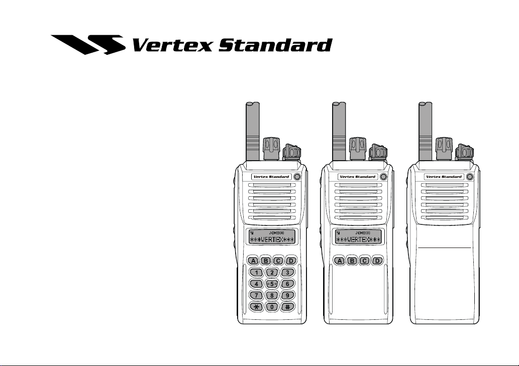
16 Key Version 4 Key Version Non-LCD Version
ERIES

CONTENTS
Warning! FCC RF Exposure Requirements ................ 2
Controls & Connectors (Non-LCD Version) ............... 4
Controls & Connectors (4-Key Version) ...................... 5
Controls & Connectors (16-Key Version) .................... 6
LCD Icons & Indicators (4- & 16-Key Versions) ........ 7
Battery Terminals .......................................................... 7
Before You Begin ........................................................... 8
Battery Pack Installation and Removal .................................8
Low Battery Indication .......................................................... 8
Battery Charging .................................................................... 9
Operation...................................................................... 10
P
reliminary Steps ..................................................... 10
Operation Quick Start .............................................. 10
Advanced Operation ................................................... 13
Programmable Key Functions and
Toggle Switch Functions
Descriptipon of Operating Functions
ARTS (Auto Range Transpond System) .................... 23
DTMF Paging System.................................................. 23
RSSI Beep ..................................................................... 23
Caller ID Display ......................................................... 23
User Set Mode .............................................................. 24
Optional Accessories .................................................... 25
............................. 15
..... 13

Congratulations!
You now have at your fingertips a valuable communications tool-a VERTEX STANDARD two-way radio!
Rugged, reliable and easy to use, your VERTEX STANDARD radio will keep you in constant touch with
your colleagues for years to come, with negligible maintenance down-time.
Please take a few minutes to read this manual carefully. The information presented here will allow you to
derive maximum performance from your radio, in case questions arise later on.
We're glad you joined the VERTEX STANDARD team. Call on us anytime, because communications is
our business. Let us help you get your message across.
Notice!: There are no owner-serviceable parts inside the radio. All service jobs must be referred to an
authorized VERTEX STANDARD Service Representative.
Consult your Authorized VERTEX STANDARD Dealer for installation of optional accessories.
Intrinisic Safety (IS) Information
IS versions of the VX-P920/-P970 series, equipped with any of the following optional units, meets the
requirements of ANSI/UL 913 6th Edition for Class I, Division 1, Groups A-D; Class II, Groups E-G; and
Class III for hazardous locations.
Battery Packs: FNB-V92LIIS
Speaker Microphone: MH-65
Substitution of components may impair intrinsic safety. Installation of FNB-V92LIIS does NOT con-
vert normal radio into IS version.
B7A, MH-50D7A, MH-66A7A, MH-66B7A
Important Notice for North American Users Regarding 406 MHz Guard Band
The U.S. Coast Guard and National Oceanographic and Atmospheric Administration have requested the
cooperation of the U.S. Federal Communications Commission in preserving the integrity of the protected
frequency range 406.0 to 406.1 MHz, which is reserved for use by distress beacons. Do not attempt to
program this apparatus, under any circumstances, for operation in the frequency range 406.0 - 406.1 MHz
if the apparatus is to be used in or near North America.
Warning - Frequency band 406 - 406.1 MHz is reserved for use ONLY as a distress beacon by the US
Coast Guard and NOAA. Under no circumstance should this frequency band be part of the
preprogrammed operating frequencies of this radio.
VX-P920/-P970 SERIES OPERATING MANUAL
1
WARNING! FCC RF EXPOSURE REQUIREMENTS
This Radio has been tested and complies with the Federal Communications Commission (FCC) RF exposure
limits for Occupational Use/Controlled exposure environment. In addition, it complies with the following Standards and Guidelines:
FCC 96-326, Guidelines for Evaluating the Environmental Effects of Radio-Frequency Radiation.
FCC OET Bulletin 65 Edition 97-01 (1997) Supplement C, Evaluating Compliance with FCC Guidelines
for Human Exposure to Radio Frequency Electromagnetic Fields.
ANSI/IEEE C95.1-1992, IEEE Standard for Safety Levels with Respect to Human Exposure to Radio Fre-
quency Electromagnetic Fields, 3 kHz to 300 GHz.
ANSI/IEEE C95.3-1992, IEEE Recommended Practice for the Measurement of Potentially Hazardous Elec-
tromagnetic Fields - RF and Microwave.
WARNING:
This radio generates RF electromagnetic energy during transmit mode. This radio is designed for and
classified as Occupational Use Only, meaning it must be used only during the course of employment by
individuals aware of the hazards, and the ways to minimize such hazards. This radio is not intended for
use by the General Population in an uncontrolled environment.
CAUTION:
To ensure that your expose to RF electromagnetic energy is within the FCC allowable limits for occupational use, always adhere to the following guidelines:
This radio is NOT approved for use by the general population in an uncontrolled exposure environ-
ment. This radio is restricted to occupational use, work related operations only where the radio operator must have the knowledge to control his or her RF exposure conditions.
When transmitting, hold the radio in a vertical position with its microphone 2 inches (5 cm) away
from your mouth and keep the antenna at least 2 inches (5 cm) away from your head and body.
2
VX-P920/-P970 SERIES OPERATING MANUAL

WARNING! FCC RF EXPOSURE REQUIREMENTS
The radio must be used with a maximum operating duty cycle not exceeding 50%, in typical Push-to-
Talk configurations.
DO NOT transmit for more than 50% of total radio use time (50% duty cycle). Transmitting more
than 50% of the time can cause FCC RF exposure compliance requirements to be exceeded.
The radio is transmitting when the red LED on the top of the radio is illuminated. You can cause the
radio to transmit by pressing the P-T-T button.
SAR compliance for body-worn use was only demonstrated for the specific belt-clip Part Number
(CLIP-920). Other body-worn accessories or configurations may NOT comply with the FCC RF exposure requirements and should be avoided.
DO NOT transmit when the radio is used in Body Worn configuration with the following accessory:
belt-clip.
It must be used ONLY for (1) there is 4 cm distance from the body during transmitting, (2) monitoring purposes, using the speaker only and (3) for carrying purposes.
Always use Vertex Standard authorized accessories.
The information listed above provides the user with the information needed to make him or her
aware of RF exposure, and what to do to assure that this radio operates with the FCC RF exposure
limits of this radio.
Electromagnetic Interference/Compatibility
During transmissions, this radio generates RF energy that can possibly cause interference with other
devices or systems. To avoid such interference, turn off the radio in areas where signs are posted to do so.
Do not operate the transmitter in areas that are sensitive to electromagnetic radiation such as hospitals, health care facilities, aircraft, and blasting sites.
VX-P920/-P970 SERIES OPERATING MANUAL
3
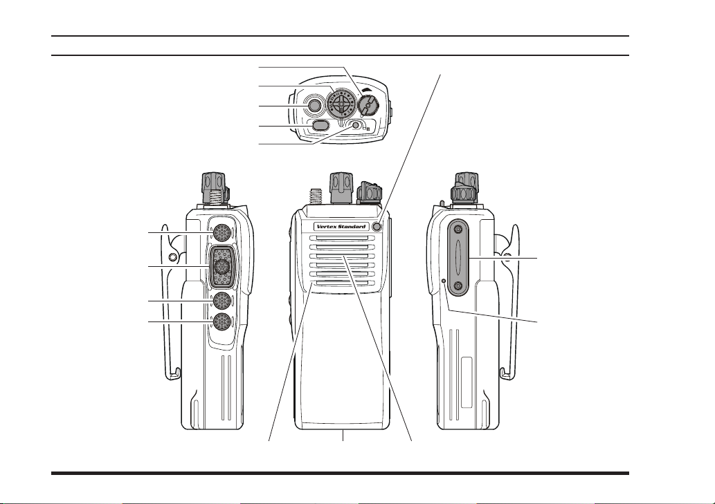
SIDE SEL 1 Key
CONTROLS & CONNECTORS
VOL/PWR Knob
CH (Channel) Selector
Antenna Jack
TOP SEL Key
TOGGLE Switch
(
NON-LCD VERSION
LED Indicator
Steady Red:
Transmitting in progress
Steady Green:
Tone Squelch in defeated condition
Blinking Green:
Busy Channel
Dealer Programmed Color
Emergency, or 2-Tone Decoded
)
Ú
:
: one of “Flashing in white,”
Ú
“Continuation changes in
sequential colors,” or “toggling the two colors.”
PTT Switch
MONITOR Button
SIDE SEL 2 Button
4
MIC/SP Jack
(
External MIC/SP
Sub Microphone
(
Noise Canceling MIC
Battery Pack LatchMain Microphone
Speaker
)
)
VX-P920/-P970 SERIES OPERATING MANUAL
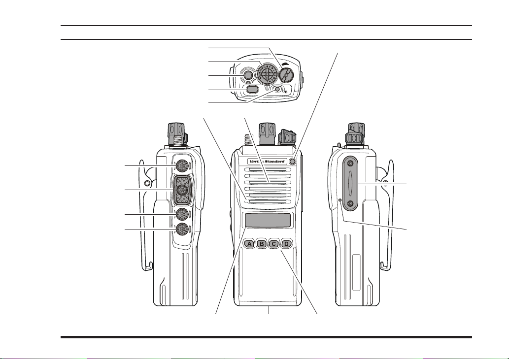
SIDE SEL Key
CONTROLS & CONNECTORS
VOL/PWR Knob
CH (Channel) Selector
Antenna Jack
TOP SEL Key
TOGGLE Switch
(
4-KEY VERSION
LED Indicator
SpeakerMain Microphone
)
Steady Red:
Transmitting in progress
Steady Green:
Tone Squelch in defeated condition
Blinking Green:
Busy Channel
Dealer Programmed Color
Emergency, or 2-Tone Decoded
: one of “Flashing in white,”
Ú
“Continuation changes in
sequential colors,” or “toggling the two colors.”
Ú
:
PTT Switch
MONITOR Button
LAMP Key
)
VX-P920/-P970 SERIES OPERATING MANUAL
MIC/SP Jack
(
External MIC/SP
Sub Microphone
(
Noise Canceling MIC
Battery Pack LatchLCD (Liquid Crystal Display
4-Button Programmable Key
)
)
5
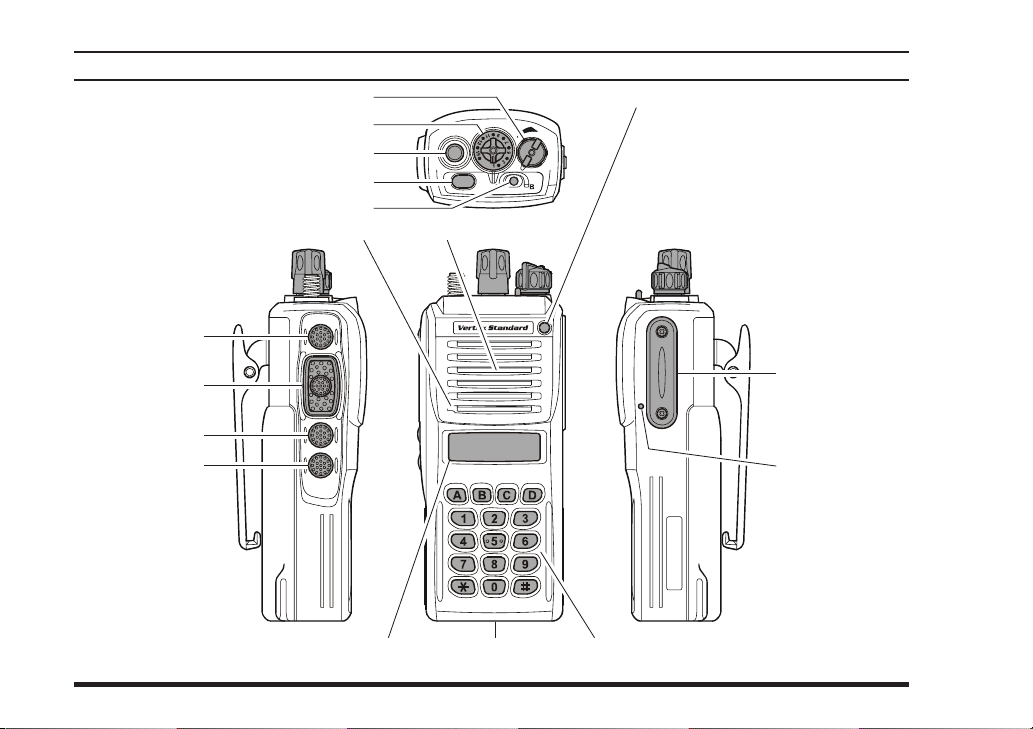
SIDE SEL Key
CONTROLS & CONNECTORS
VOL/PWR Knob
CH (Channel) Selector
Antenna Jack
TOP SEL Key
TOGGLE Switch
SpeakerMain Microphone
(
16-KEY VERSION
LED Indicator
Steady Red:
Steady Green:
Blinking Green:
Dealer Programmed Color
)
Transmitting in progress
Tone Squelch in defeated condition
Busy Channel
Emergency, or 2-Tone Decoded
: one of “Flashing in white,”
Ú
“Continuation changes in
sequential colors,” or “toggling the two colors.”
Ú
:
PTT Switch
MONITOR Button
LAMP Button
6
MIC/SP Jack
(
External MIC/SP
Sub Microphone
(
Noise Canceling MIC
)
Battery Pack LatchLCD (Liquid Crystal Display
16-Button DTMF Keypad (16-key version only)
)
)
VX-P920/-P970 SERIES OPERATING MANUAL
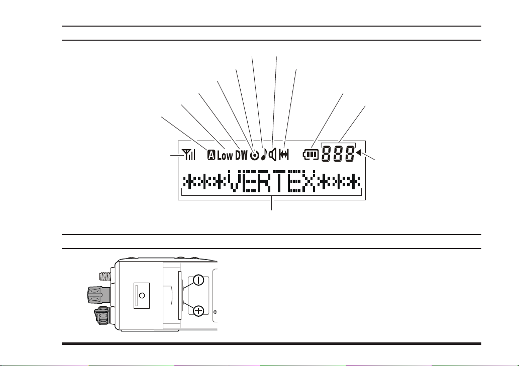
LCD ICONS & INDICATORS
This channel on “SCAN” List
Priority Scan is activated
“DUAL WATCH” is activated
Low Transmit Power Mode On
“Analog Transmission”
is activated
RSSI Indicator
(four steps)
(
16-KEY & 4-KEY VERSIONS
“CALL” Indicator Receiver Monitor
“Talk-Around” is enabled
12 Character Alpha-numeric Display
BATTERY TERMINALS
Maximum Input Voltage: 8.4 V DC 8.4 V DC
Maximum Input Current: 2.5 A 2.5 A
Maximum Input Power: 21 W 21 W
Maximum Internal Capacitance: 51.31 µF 51.28 µF
Maximum Internal Inductance: 5.50 µH 5.48 µH
)
Battery Indicator
SUB-LCD
888: Channel Group Number
-P-: Priority Channel
-H-: Home Channel
In: ARTS “In Range”
Out: ARTS “Out of Range”
“Group Scan” is enabled
VHF Model UHF Model
VX-P920/-P970 SERIES OPERATING MANUAL
7
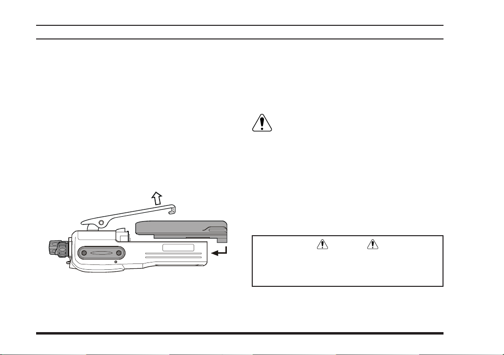
BEFORE YOU BEGIN
Battery Pack Installation and Removal
To install the battery, hold the transceiver with
your left hand, so your palm is over the speaker
and your thumb is on the top of the belt clip. Carefully mate the battery’s four insertion slots with
their corresponding alignment tabs on the transceiver case, while tilting the Belt Clip outward.
Proper alignment occurs with the battery pack
offset about 1/2 inch from the top edge of the battery compartment.
Guide the pack on to the tabs with a slight inward
pressure, then slide the battery pack upward, until it locks in place with a “Click.”
Tilt the Belt Clip
Insert the Battery Pack
To remove the battery, turn the radio off and re-
move any protective cases. Slide the Battery Pack
Latch on the bottom of the radio toward the front
panel while sliding the battery down about 1/2
inch. Then lift the battery out from the radio while
unfolding the Belt Clip.
Do not attempt to open any of the rechargeable Lithium-Ion packs, as they could ex-
plode if accidentally short-circuited.
Low Battery Indication
As the battery discharges during use, the voltage
gradually becomes lower. When the battery voltage
becomes to low, substitute a freshly charged battery
and recharge the depleted pack. The LED indicator
on the top of the radio will blink red when the battery voltage is low.
Caution
Danger of explosion if battery is replaced with
an incorrect battery. Replace only with the same
or equivalent type.
8
VX-P920/-P970 SERIES OPERATING MANUAL
 Loading...