

Vertex Standard VX-P920 Series Operating Manual
VX-P920 series
oPerating ManuaL
16-Key Version 4-Key Version non-LCD Version
Vertex Standard LMR, Inc.

Contents
Important Note ................................................................... 2
Intrinsic Safety (IS) Information ...................................... 3
Warning! FCC RF Exposure Requirements .................... 4
Controls & Connectors (16-Key Version) ........................6
Controls & Connectors (4-Key Version) ..........................7
Controls & Connectors (Non-LCD Version) ................... 8
LCD Icons & Indicators (16- & 4-Key Versions) ............9
Battery Terminals ............................................................. 10
Before You Begin .............................................................. 11
Battery Pack Installation and Removal ....................... 11
Battery Charging (VAC-UNI: CD-58/PA-55) ............. 12
Battery Charging (VAC-920: CD-31/PA-42) .............. 14
Low Battery Indication ............................................... 15
Operation .......................................................................... 16
Preliminary Steps ........................................................ 16
Operation Quick Start ................................................. 16
Automatic Time-Out Timer......................................... 18
Advanced Operation ........................................................ 20
Programmable Key and Toggle Switch Functions ..... 20
Description of Operating Functions ........................... 22
ARTS™ (Auto Range Transpond System) .................... 30
DTMF Paging System ...................................................... 30
MDC1200® Encoding ............................................. 30
RSSI Beep ............................................................... 30
Caller ID Display .................................................... 31
LOCK ...................................................................... 31
User Set Mode......................................................... 32
Optional Accessories .............................................. 34
Warranty Policy ..................................................... 36

Congratulations!
You now have at your ngertips a valuable communications tool-a Vertex Standard two-way radio! Rugged, reliable and easy to use, your Vertex Standard radio will keep you in constant touch with your colleagues for years to
come, with negligible maintenance down-time. Please take a few minutes to read this manual carefully. The information presented here will allow you to derive maximum performance from your radio, in case questions arise
later on.
We’re glad you joined the Vertex Standard team. Call on us anytime, because communications is our business. Let
us help you get your message across.
VX-P920 SerieS OPerating Manual
1

VX-P920 SerieS OPerating Manual
important note
There are no owner-serviceable parts inside the radio. All service jobs must be referred to an authorized Vertex
r
Standard Service Representative. Consult your Authorized Vertex Standard Dealer for installation of optional
accessories.
In order to maintain the specied water integrity performance, periodic maintenance is recommended.
r
Should the radio sustain a severe shock (e.g. if it is dropped), the water integrity may be compromised, requir-
r
ing service. Should this occur, contact your Authorized Vertex Standard Dealer.
Important Notice for North American Users Regarding 406 MHz Guard Band
The U.S. Coast Guard and National Oceanographic and Atmospheric Administration have requested the
cooperation of the U.S. Federal Communications Commission in preserving the integrity of the protected
frequency range 406.0 to 406.1 MHz, which is reserved for use by distress beacons. Do not attempt to program this apparatus, under any circumstances, for operation in the frequency range 406.0 - 406.1 MHz if
the apparatus is to be used in or near North America.
Warning - Frequency band 406 - 406.1 MHz is reserved for use ONLY as a distress beacon by the US
Coast Guard and NOAA. Under no circumstance should this frequency band be part of the pre programmed operating frequencies of this radio.
2

VX-P920 SerieS OPerating Manual
IntrInsIc safety (Is) InformatIon
IS versions of the
UL 913 5th Edition for Class I, Division 1, Groups C-D; Class II, Groups E-G; and Class III for hazardous locations.
Battery Packs:
Speaker Microphone:
Multi Band Receiver Unit:
Never charge the battery in the hazard areas.
r
Never install/removal the battery in the hazard areas.
r
Never install/remove the optional unit (includes the Speaker Microphone) in the hazard areas.
r
The
r
r
r
r
VX-P920
cally charged by the rapid ow of a non-conductive media.
Ensure that there is no external damage to the radio, antenna or battery before entering the potentially explo-
sive atmospheres, as it might compromise the safety of the unit. eg an antenna with a damaged end or insulation must be replaced before use in any potentially explosive atmospheres.
Substitution of components may impair intrinsic safety. Installation of
mal radio into IS version.
To acquire the IS version of the
purchase.
VX-P920
shall not be directly installed or used in any process where its enclosure might be electrostati-
, equipped with any of the following optional units, meets the requirements of ANSI/
FNB-V92LIIS
MH-50
SRX-3, SRX-4
VX-P920
,
D7A
MH-66
, you much select the Intrinsically Safe battery option at the time of
A7A
,
MH-66
B7A
FNB-V92LIIS
does NOT convert nor-
3
VX-P920 SerieS OPerating Manual
Warning! fCC rf exposure requirements
This Radio has been tested and complies with the Federal Communications Commission (FCC) RF exposure limits for Occupational Use/Controlled exposure environment. In addition, it complies with the following Standards
and Guidelines:
FCC 96-326, Guidelines for Evaluating the Environmental Effects of Radio-Frequency Radiation.
r
FCC OET Bulletin 65 Edition 97-01 (1997) Supplement C, Evaluating Compliance with FCC Guidelines for
r
Human Exposure to Radio Frequency Electromagnetic Fields.
ANSI/IEEE C95.1-1992, IEEE Standard for Safety Levels with Respect to Human Exposure to Radio Fre-
r
quency Electromagnetic Fields, 3 kHz to 300 GHz.
ANSI/IEEE C95.3-1992, IEEE Recommended Practice for the Measurement of Potentially Hazardous Electro-
r
magnetic Fields - RF and Microwave.
WARNING:
This radio generates RF electromagnetic energy during transmit mode. This radio is designed for and classied as Occupational Use Only, meaning it must be used only during the course of employment by individuals aware of the hazards, and the ways to minimize such hazards. This radio is not intended for use by
the General Population in an uncontrolled environment.
CAUTION:
To ensure that your expose to RF electromagnetic energy is within the FCC allowable limits for occupational use, always adhere to the following guidelines:
This radio is NOT approved for use by the general population in an uncontrolled exposure environment.
¦
This radio is restricted to occupational use, work related operations only where the radio operator must
have the knowledge to control his or her RF exposure conditions.
When transmitting, hold the radio in a vertical position with its microphone 2 inches (5 cm) away from
¦
your mouth and keep the antenna at least 2 inches (5 cm) away from your head and body.
4

VX-P920 SerieS OPerating Manual
Warning! fCC rf exposure requirements
The radio must be used with a maximum operating duty cycle not exceeding 50%, in typical Push-to-
¦
Talk congurations.
DO NOT transmit for more than 50% of total radio use time (50% duty cycle). Transmitting more than
50% of the time can cause FCC RF exposure compliance requirements to be exceeded.
The radio is transmitting when the red LED on the front panel of the radio is illuminated. You can
cause the radio to transmit by pressing the P-T-T button.
SAR compliance for body-worn use was only demonstrated for the specific belt-clip Part Number
¦
(CLIP-920). Other body-worn accessories or congurations may NOT comply with the FCC RF exposure requirements and should be avoided.
DO NOT transmit when the radio is used in Body Worn configuration with the following accessory:
¦
belt-clip.
It must be used ONLY for (1) there is 1.5 inches (4 cm) distance from the body during transmitting,
(2) monitoring purposes, using the speaker only and (3) for carrying purposes.
Always use Vertex Standard authorized accessories.
¦
The information listed above provides the user with the information needed to make him or her aware
¦
of RF exposure, and what to do to assure that this radio operates with the FCC RF exposure limits of
this radio.
Electromagnetic Interference/Compatibility
¦
During transmissions, this radio generates RF energy that can possibly cause interference with other de-
vices or systems. To avoid such interference, turn off the radio in areas where signs are posted to do so.
Do not operate the transmitter in areas that are sensitive to electromagnetic radiation such as hospitals,
health care facilities, aircraft, and blasting sites.
5
VX-P920 SerieS OPerating Manual
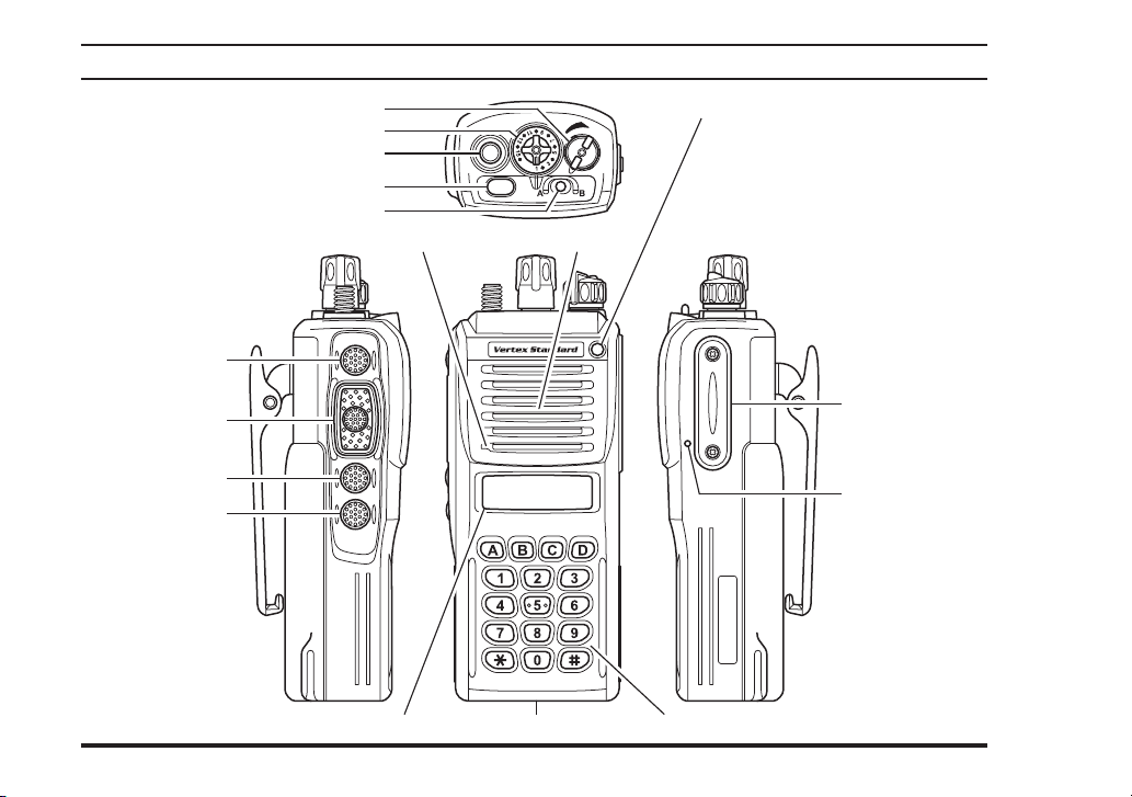
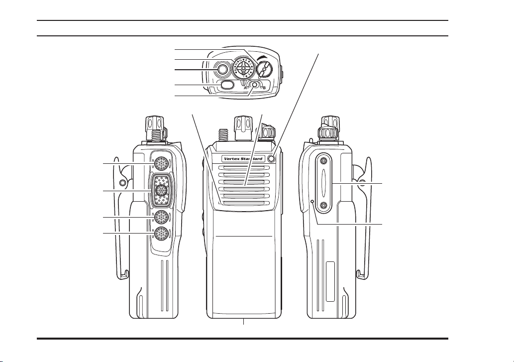
Control & ConneCtors (16-Key Version
)
SIDE SEL Key
PTT Switch
MONITOR Button
LAMP Button
6
VOL/PWR Knob LED Indicator
CH (Channel) Selector
Antenna Jack
TOP SEL Key
TOGGLE Switch
SpeakerMain Microphone
LCD (Liquid Crystal Display
)
Battery Pack Latch 16-Button DTMF Keypad
Steady Red:
Transmitting in progress
Blinking Green:
Busy Channel
Steady Green:
Tone Squelch in defeated condition
Dealer Programmed Color
Emergency, 5-Tone Decoded, or
2-Tone Decoded
one of “Flashing in white”,
ø
“C ont inuat ion chang es
in sequentia l colors”, or
“Toggling the two colors”.
ø
MIC/SP Jack
(
External MIC/SP
Sub Microphone
(
Noise Canceling MIC
)
)
VX-P920 SerieS OPerating Manual
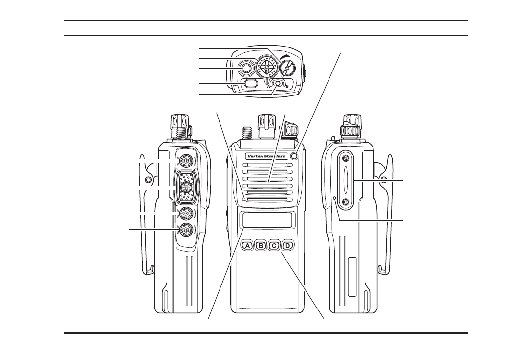
Control & ConneCtors (4-Key Version
)
VOL/PWR Knob LED Indicator
CH (Channel) Selector
Antenna Jack
TOP SEL Key
TOGGLE Switch
SIDE SEL Key
PTT Switch
MONITOR Button
LAMP Button
LCD (Liquid Crystal Display
Steady Red:
Transmitting in progress
Blinking Green:
Busy Channel
Steady Green:
Tone Squelch in defeated condition
Dealer Programmed Color
SpeakerMain Microphone
)
Battery Pack Latch 4-Button Programmable Key
Emergency, 5-Tone Decoded, or
2-Tone Decoded
one of “Flashing in white”,
ø
“C ont inuat ion chang es
in sequentia l colors”, or
“Toggling the two colors”.
ø
MIC/SP Jack
(
External MIC/SP
Sub Microphone
(
Noise Canceling MIC
)
)
7
VX-P920 SerieS OPerating Manual
Control & ConneCtors (non-lCD Version
)
SIDE SEL Key
PTT Switch
MONITOR Button
LAMP Button
8
VOL/PWR Knob LED Indicator
CH (Channel) Selector
Antenna Jack
TOP SEL Key
TOGGLE Switch
SpeakerMain Microphone
Battery Pack Latch
Steady Red:
Transmitting in progress
Blinking Green:
Busy Channel
Steady Green:
Tone Squelch in defeated condition
Dealer Programmed Color
Emergency, 5-Tone Decoded, or
2-Tone Decoded
one of “Flashing in white”,
ø
“C ont inuat ion chang es
in sequentia l colors”, or
“Toggling the two colors”.
ø
MIC/SP Jack
(
External MIC/SP
Sub Microphone
(
Noise Canceling MIC
)
)
VX-P920 SerieS OPerating Manual
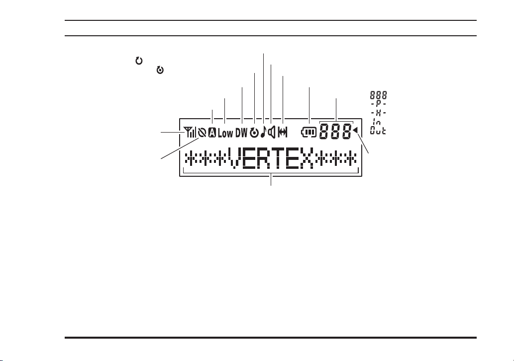
lCD iCons & inDiCators (16-Key & 4-Key Versions
: This channel on the “SCAN” List
: “Priority Scan” is activated
“Dual Watch” is activated
Low Transmit Power Mode On
Option Switch (Key Function) is activated
RSSI Indicator (four steps
)
)
“CALL” Indicator
Receiver Monitor
“Talk-Around” is enabled
Battery Indicator
SUB-LCD : Channel Group Number
: Priority Channel
: Home Channel
: ARTS™ “In Range”
: ARTS™ “Out of Range”
Encryption is activated
“Group Scan” is enabled
12 Character Alpha-numeric Display
9
VX-P920 SerieS OPerating Manual
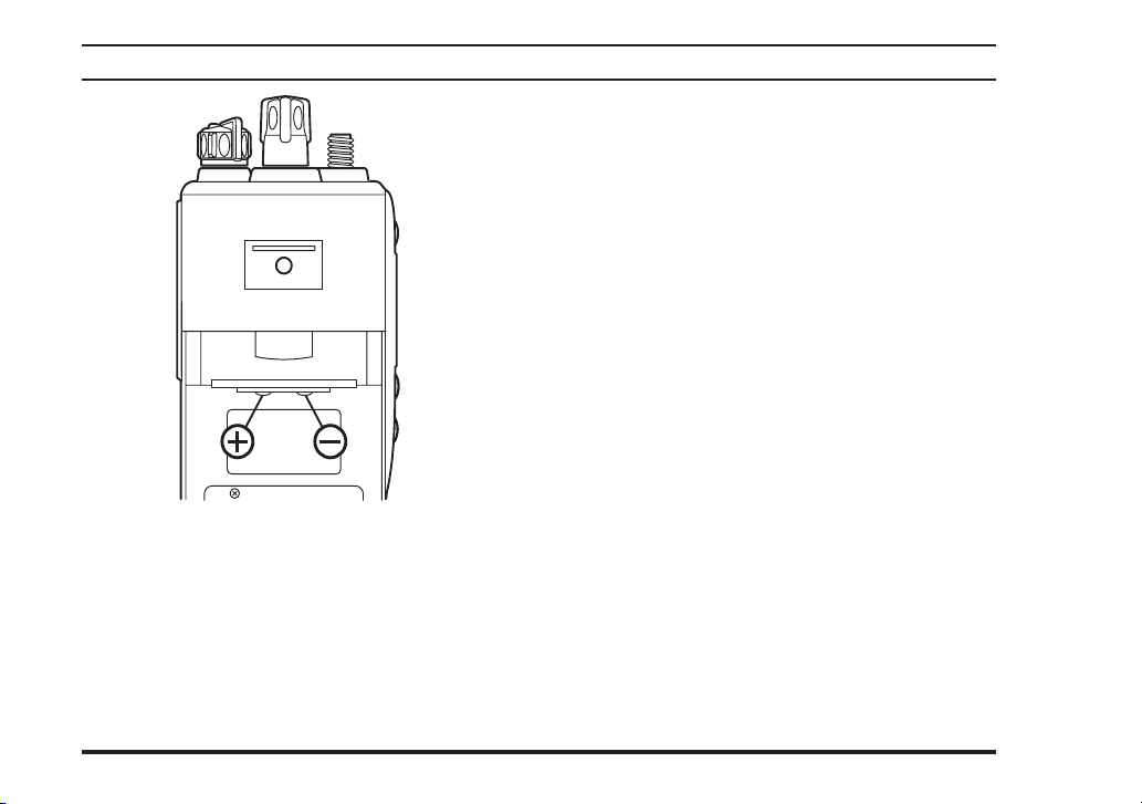
Battery terminals
VHF Model UHF Model
Maximum Input Voltage: 8.4 V DC 8.4 V DC
Maximum Input Current: 2.5 A 2.5 A
Maximum Input Power: 21 W 21 W
Maximum Internal Capacitance: 50.31 μF 51.28 μF
Maximum Internal Inductance: 5.50 μH 5.48 μH
10
 Loading...