

Digital two-way RaDio SyStem
VXD-7200
Operating Manual

1
Declaration of conformity
This declaration is applicable to your radio only if your radio is labeled with the FCC logo shown below.
DECLARATION OF CONFORMITY
Per FCC CFR 47 Part 2 Section 2.1077(a)
Name: Vertex Standard Co., Ltd.
Address: US Headquarters: 10900 Walker Street, Cypress, CA 90630 U.S.A.
Phone Number: 1-800-283-7839
Hereby declares that the product:
Model Name: VXD-7200
conforms to the following regulations:
FCC Part 15, subpart B, section 15.107(a), 15.107(d) and section 15.109(a)
Class B Digital Device
As a personal computer peripheral, this device complies with Part 15 of the FCC
Rules. Operation is subject to the following two conditions:
1. This device may not cause harmful interference, and
2. This device must accept any interference received, including interference
that may cause undesired operation.
Declaration of conformity

2
Note: This equipment has been tested and found to comply with the limits for a
Class B digital device, pursuant to part 15 of the FCC Rules. These limits
are designed to provide reasonable protection against harmful interference
in a residential installation. This equipment generates, uses and can radiate radio frequency energy and, if not installed and used in accordance with
the instructions, may cause harmful interference to radio communications.
However, there is no guarantee that interference will not occur in a particular
installation.
If this equipment does cause harmful interference to radio or television reception,
which can be determined by turning the equipment off and on, the user is encouraged to try to correct the interference by one or more of the following measures:
r
Reorient or relocate the receiving antenna.
r
Increase the separation between the equipment and receiver.
r
Connect the equipment into an outlet on a circuit different from that to which the
receiver is connected.
r
Consult the dealer or an experienced radio/TV technician for help.
Declaration of conformity

3
contents
contents
This User Guide contains all the information you
need to use the Vertex Standard VXD-7200 Digital
Two-Way Radio System.
Product Safety and RF Energy Exposure .........6
Important Safety Information ...........................14
Software Version ............................................... 14
Computer Software Copyrights .......................15
Getting Started ................................................... 16
How to Use This User Guide .......................... 16
What Your Dealer/System Administrator
Can Tell You ................................................... 16
Powering Up the Radio .................................. 17
Adjusting the Volume ...................................... 17
Identifying Radio Controls ................................ 18
Radio Controls ................................................ 18
Programmable Buttons ................................... 19
Assignable Radio Functions ...................... 19
Assignable Settings/Utility Functions ........20
Accessing the Programmed Functions ........... 21
Push-To-Talk (PTT) Button ............................. 22
Switching Between Conventional Analog
and Digital Mode ............................................ 23
Identifying Status Indicators ............................ 24
Display Icons .................................................. 24
Call Icons ........................................................ 25
Sent Item Icons .............................................. 26
LED Indicators ................................................ 26
Audio Tones .................................................... 27
Indicator Tones ............................................... 27
Receiving and Making Calls ............................. 28
Selecting a Zone ............................................ 28
Selecting a Radio Channel, Subscriber Alias
or ID, or Group Alias or ID .............................. 29
Receiving and Responding to a Radio Call .... 30
Receiving and Responding to
a Group Call .............................................. 30
Receiving and Responding to
a Private Call ............................................. 31
Receiving an All Call..................................32
Making a Radio Call ....................................... 32
Making a Call with the Channel Rocker ....33
Making a Group Call ............................ 33
Making a Private Call ........................... 33
Making an All Call ................................. 34
Making a Group or Private Call
with the One Touch Access Button ............ 35
Talkaround ...................................................... 36
Permanent Monitor ......................................... 37

4
Advanced Features ...........................................38
Radio Check ................................................... 38
Sending a Radio Check............................. 38
Remote Monitor .............................................. 40
Initiating Remote Monitor ..........................40
Stopping Remote Monitor.......................... 41
Scan Lists ....................................................... 42
Viewing an Entry in the Scan List .............. 42
Editing the Scan List.................................. 42
Adding a New Entry to the Scan List .... 42
Deleting an Entry from the Scan List .... 43
Setting and Editing Priority
for an Entry in the Scan List ................. 43
Scan ............................................................. 44
Starting and Stopping Scan....................... 44
Responding to a Transmission
During a Scan............................................ 45
Deleting a Nuisance Channel .................... 45
Restoring a Nuisance Channel.................. 46
Contacts Settings ........................................... 46
Making a Group Call from Contacts .......... 47
Making a Private Call from Contacts ......... 48
Call Indicator Settings .................................... 49
Activating and Deactivating Call Ringers
for Private Calls ......................................... 49
Activating and Deactivating Call Ringers
for Text Messaging .................................... 49
Assigning Ring Styles................................ 50
Escalating Alarm Tone Volume .................. 50
Call Log Features ........................................... 51
Viewing Recent Calls ................................51
Missed Call Screen ...................................51
Deleting a Call from a Call List .................. 52
Call Alert Operation ........................................ 53
Receiving and Responding
to a Call Alert ............................................. 53
Making a Call Alert
from the Contacts List ...............................53
Making a Call Alert
with the One Touch Access Button ............ 54
Emergency Operation .................................... 54
Receiving an Emergency Alarm ................ 55
Responding to an Emergency Alarm ......... 56
Sending an Emergency Alarm ................... 57
Sending an Emergency Alarm with Call .... 57
Sending an Emergency Alarm
with Voice to Follow ................................... 58
Reinitiating an Emergency Mode ..............59
Exiting Emergency Mode ..........................60
Text Messaging Features ............................... 60
Sending a Quick Text Message ................. 60
Sending a Quick Text Message
with the One Touch Access Button ............ 62
Managing Text Messages
in the Drafts Folder .................................... 62
contents

5
contents
Viewing a Saved Text Message ........... 61
Deleting a Saved Text Message
from Drafts ........................................... 62
Managing Fail-to-Send Text Messages ..... 62
Resending a Text Message .................. 62
Forwarding a Text Message ................. 62
Managing Sent Text Messages ............ 63
Viewing a Sent Text Message ..............63
Sending a Sent Text Message ............. 63
Deleting All Sent Text Messages
from Sent Items .................................... 65
Receiving a Text Message ........................ 65
Reading a Text Message ........................... 65
Managing Received Text Messages .......... 66
Viewing a Text Message
from the Inbox ...................................... 66
Replying to a Text Message
with Quick Text ..................................... 66
Deleting a Text Message
from the Inbox ...................................... 67
Deleting All Text Messages
from the Inbox ...................................... 68
Privacy ............................................................ 69
Security .......................................................... 70
Radio Disable ............................................ 70
Radio Enable ............................................. 71
Lone Worker ................................................... 72
Utilities ............................................................ 72
Setting the Squelch Level.......................... 72
Setting the Power Level ............................73
Turning the Voice Operating Transmission
(VOX) Feature On or Off ........................... 73
Turning the Public Address System
On or Off .................................................... 74
Turning the External Public
Address System On or Off ........................74
Controlling the Display Backlight ............... 75
Turning Horns/Lights On or Off ................. 75
Turning the Radio Tones/Alerts
On or Off .................................................... 76
Setting the Tone Alert Volume
Offset Level ............................................... 76
Turning the Talk Permit Tone On or Off ..... 77
Turning the LED Indicators On or Off ........ 77
Turning the Introduction Screen
On or Off .................................................... 78
Accessing General Radio Information ...... 78
Checking the Radio ID ......................... 78
Checking the Firmware Version ........... 79
Checking the Codeplug Version ........... 79
Accessories .......................................................80

6
ATTENTION!
BEFORE USING THIS RADIO, READ THIS CHAPTER WHICH CONTAINS IMPORTANT OPERATING INSTRUCTIONS FOR SAFE USAGE AND RF ENERGY AWARENESS AND CONTROL
INFORMATION FOR COMPLIANCE WITH RF ENERGY EXPOSURE LIMITS IN APPLICABLE
NATIONAL AND INTERNATIONAL STANDARDS.
The information provided in this document supersedes the general safety information contained in user
guides published prior to February 2002.
RF Energy Exposure Awareness and Control Information, and Operational Instructions for FCC Occupational Use Requirements
NOTICE: This radio is intended for use in occupational/controlled conditions, where users have full
knowledge of their exposure and can exercise control over their exposure to meet FCC limits. This radio device is NOT authorized for general population, consumer, or any other use.
This 2-way radio uses electromagnetic energy in the radio frequency (RF) spectrum to provide communications between two or more users over a distance. It uses radio frequency (RF) energy or radio waves to send
and receive calls. RF energy is one form of electromagnetic energy. Other forms include, but are not limited
to, sunlight and x-rays. RF energy, however, should not be confused with these other forms of electromagnetic energy, which when used improperly, can cause biological damage. Very high levels of x-rays, for example, can damage tissues and genetic material.
Experts in science, engineering, medicine, health, and industry work with organizations to develop standards
for safe exposure to RF energy. These standards provide recommended levels of RF exposure for both workers and the general public. These recommended RF exposure levels include substantial margins of protection.
All Vertex Standard 2-way radios are designed, manufactured, and tested to ensure they meet government-
established RF exposure levels. In addition, manufacturers also recommend specic operating instructions
ProDuct safety anD rf energy exPosure

7
to users of 2-way radios. These instructions are important because they inform users about RF energy exposure and provide simple procedures on how to control it.
Please refer to the following Web sites for more information on what RF energy exposure is and how to control your exposure to assure compliance with established RF exposure limits.
http://www.fcc.gov/oet/rfsafety/rf-faqs.html
http://www.osha.gov/SLTC/radiofrequencyradiation/index.html
Federal Communication Commission Regulations
The FCC rules require manufacturers to comply with the FCC RF energy exposure limits for mobile 2-way
radios before they can be marketed in the U.S. When 2-way radios are used as a consequence of employment, the FCC requires users to be fully aware of and able to control their exposure to meet occupational
requirements. Exposure awareness can be facilitated by the use of a label directing users to specic user
awareness information. Your Vertex Standard 2-way radio has a RF exposure product label. Also, your Vertex
Standard user manual, or separate safety booklet, includes information and operating instructions required to
control your RF exposure and to satisfy compliance requirements.
Compliance with RF Exposure Standard
Your Vertex Standard two-way radio is designed and tested to comply with a number of national and international standards and guidelines (listed below) regarding human exposure to radio frequency electromagnetic
energy. This radio complies with the IEEE and ICNIRP exposure limits for occupational/controlled RF exposure environment at duty factors of up to 50% talk-50% listen and is authorized by the FCC for occupational
use. In terms of measuring RF energy for compliance with the FCC exposure guidelines, your radio antenna
radiates measurable RF energy only while it is transmitting (during talking), not when it is receiving (listening)
or in standby mode.
ProDuct safety anD rf energy exPosure

8
Your Vertex Standard two-way radio complies with the following RF energy exposure standards and
guidelines:
United States Federal Communications Commission, Code of Federal Regulations; 47CFR part 2 sub-
part J
American National Standards Institute (ANSI) / Institute of Electrical and Electronic Engineers (IEEE) C95.
1-1992
Institute of Electrical and Electronic Engineers (IEEE) C95.1-1999 Edition
International Commission on Non-Ionizing Radiation Protection (ICNIRP) 1998
Ministry of Health (Canada) Safety Code 6. Limits of Human Exposure to Radiofrequency Electromag-
netic Fields in the Frequency Range from 3 kHz to 300 GHz, 1999
Australian Communications Authority Radiocommunications (Electromagnetic Radiation - Human Expo-
sure) Standard, 2003
ANATEL, Brasil Regulatory Authority, Resolution 256 (April 11, 2001) “additional requirements for SMR,
cellular, and PCS product certication.”
RF Exposure Compliance and Control Guidelines and Operating Instructions
To control exposure to yourself and others and to ensure compliance with the RF exposure limits, always adhere to the following procedures.
Guidelines:
User awareness instructions should accompany device when transferred to other users.
Do not use this device if the operational requirements described herein are not met.
Instructions:
Transmit no more than the rated duty factor of 50% of the time. To transmit (talk), push the Push-To-Talk
(PTT) button or, for radios equipped with VOX, speak into the microphone. The red LED will illuminate
when the radio is transmitting. To receive calls, release the PTT button, or, for radios equipped with VOX,
stop talking. The red LED will extinguish when the radio stops transmitting. Transmitting 50% of the time,
or less, is important because this radio generates measurable RF energy exposure only when transmitting
ProDuct safety anD rf energy exPosure

9
(in terms of measuring for standards compliance).
Transmit only when people outside the vehicle are at least the recommended minimum lateral
distance away, as shown in Table 1, from the body of a vehicle with a properly installed antenna.
This separation distance will ensure that there is sufcient distance from a properly installed (according to
installation instructions) externally-mounted antenna to satisfy the RF exposure requirements in the standards listed above.
NOTE: Table 1 below lists the recommended lateral distance for people in an uncontrolled environment
from the body of a vehicle with an approved, properly installed transmitting antenna (i.e., monopoles over a ground plane, or dipoles) at several different ranges of rated radio power for mobile
radios installed in a vehicle.
Table 1. Rated Power of Vehicle-Installed Mobile Two-Way Radio and
Recommended Minimum Lateral Distance from Vehicle Body
Mobile Radio Rated Power (see Note) Minimum Lateral Distance from Vehicle Body
Less than 7 watts 8 inches (20 centimeters)
7 to 15 watts 1 foot (30 centimeters)
16 to 39 watts 2 feet (60 centimeters)
40 to 110 watts 3 feet (90 centimeters)
When a mobile radio is used in conjunction with another co-located transmitter such as a Vehicular
Repeater, it is the vehicle operator’s responsibility to take appropriate steps to keep bystanders at the
required separation distance from the vehicle to ensure compliance with the FCC’s RF energy exposure
limits for the general population. See the co-located transmitter’s user manual for more details.
NOTE: If you are not sure of the rated power of your radio, contact your Vertex Standard representative or
dealer and supply the radio model number found on the radio model label. If you can not determine
the rated power out, then assure 3-feet separation from the body of the vehicle. The maximum power
shown on the FCC Grant may be higher than the rated power allowing for production variation.
ProDuct safety anD rf energy exPosure

10
Mobile Antenna Installation Guidelines
These mobile antenna installation guidelines are limited to metal body motor vehicles or vehicles with ap-
propriate ground planes.
Antennas should be installed in the center area of the roof or the trunk lid taking into account exposure
conditions of backseat passengers and according to the specic instructions and restrictions in the Radio
Installation Manual along with the requirements of the antenna supplier.
Trunk lid installations are limited to vehicles with clearly dened at trunk lids, and in some cases, to spe-
cic radio models and antennas. See the Radio Installation Manual for specic information on how and
where to install specic types of approved antennas to facilitate recommended operating distances to all
potentially exposed persons.
Use only the Vertex Standard -approved, supplied antenna or a Vertex Standard-approved replace-
ment antenna. Unauthorized antennas, modications, or attachments could damage the radio and may
result in non-compliance with RF Safety Standards.
Approved Accessories
This radio has been tested and meets RF Safety Standards when used with the Vertex Standard acces-
sories supplied or designated for this product. Use of other accessories may result in non-compliance with
RF Safety Standards.
For a list of Vertex Standard -approved antennas, visit the following Web site, which lists approved acces-
sories for your radio model:
http://www.vertexstandard.com/lmr.
ProDuct safety anD rf energy exPosure

11
Compliance and Control Guidelines and Operating Instructions for Mobile Two-Way Radios Installed
as Fixed Site Control Stations
If mobile radio equipment is installed at a xed location and operated as a control station or as a xed unit,
the antenna installation must comply with the following requirements in order to ensure optimal performance
and compliance with the RF energy exposure limits in the standards and guidelines listed on page 4:
The antenna should be mounted outside the building on the roof or a tower if at all possible.
As with all xed site antenna installations, it is the responsibility of the licensee to manage the site in ac-
cordance with applicable regulatory requirements and may require additional compliance actions such as
site survey measurements, signage, and site access restrictions in order to ensure that exposure limits
are not exceeded.
For additional installation information, see the guidelines for minimum separation distances provided
above in the RF Exposure Compliance and Control Guidelines and Operating Instructions section of this
document.
Electromagnetic Interference/Compatibility
NOTE: Nearly every electronic device is susceptible to electromagnetic interference (EMI) if inadequately
shielded, designed, or otherwise congured for electromagnetic compatibility. It may be necessary to
conduct compatibility testing to determine if any electronic equipment used in or around vehicles or near
xed site antenna is sensitive to external RF energy or if any procedures need to be followed to eliminate or mitigate the potential for interaction between the radio transmitter and the equipment or device.
Facilities
To avoid electromagnetic interference and/or compatibility conicts, turn off your radio in any facility where
posted notices instruct you to do so. Hospitals or health care facilities may be using equipment that is sensitive to external RF energy.
ProDuct safety anD rf energy exPosure

12
Vehicles
To avoid possible interaction between the radio transmitter and any vehicle electronic control modules, such
as ABS, engine, or transmission controls, the radio should be installed only by an experienced installer and
the following precautions should be used when installing the radio:
1. Refer to the manufacturer’s instructions or other technical bulletins for recommendations on radio installation.
2. Before installing the radio, determine the location of the electronic control modules and their harnesses in
the vehicle.
3. Route all radio wiring, including the antenna transmission line, as far away as possible from the electronic
control units and associated wiring.
Driver Safety
Check the laws and regulations on the use of radios in the area where you drive. Always obey them.
When using your radio while driving, please:
Give full attention to driving and to the road.
Pull off the road and park before making or answering a call if driving conditions so require.
ProDuct safety anD rf energy exPosure

13
Operational Warnings
For Vehicles with an Air Bag
Do not mount or place a mobile radio in the area over an air bag or in the air bag deployment
area. Air bags inate with great force.
If a radio is placed in the air bag deployment area and the air bag inates, the radio may be
propelled with great force and cause serious injury to occupants of the vehicle.
Potentially Explosive Atmospheres
Turn off your radio prior to entering any area with a potentially explosive atmosphere. Sparks
in a potentially explosive atmosphere can cause an explosion or re resulting in bodily injury
or even death.
The areas with potentially explosive atmospheres include fueling areas such as below decks
on boats, fuel or chemical transfer or storage facilities, and areas where the air contains
chemicals or particles such as grain, dust or metal powders. Areas with potentially explosive
atmospheres are often, but not always, posted.
Blasting Caps and Blasting Areas
To avoid possible interference with blasting operations, turn off your radio when you are near
electrical blasting caps, in a blasting area, or in areas posted: “Turn off two-way radio.” Obey
all signs and instructions.
For radios installed in vehicles fueled by liqueed petroleum gas, refer to the (U.S.) National
Fire Protection Association standard, NFPA 58, for storage, handling, and/or container information. For a copy of the LP-gas standard, NFPA 58, contact the National Fire Protection Association, One Battery Park, Quincy, MA.
ProDuct safety anD rf energy exPosure
14
imPortant safety information
Product Safety and RF Exposure Compliance
Before using this product, read the “Product
Safety and RF Exposure chapter” beginning with page 6.
ATTENTION!
This radio is restricted to occupational use only
to satisfy FCC RF energy exposure requirements.
For a list of Vertex Standard-approved antennas,
batteries, and other accessories, visit the following
website: http://www.vertexstandard.com/lmr
software Version
All the features described in the following sections
are supported by the radio’s software version 1.0
Build 10 or later.
See Checking the Firmware Version on page 79
to determine your radio’s software version.
Check with your dealer or system administrator for
more details of all the features supported.
imPortant safety information

15
comPuter software coPyrights
The Vertex Standard products described in this
manual may include copyrighted Vertex Standard
computer programs stored in semiconductor memories or other media. Laws in the United States
and other countries preserve for Vertex Standard
certain exclusive rights for copyrighted computer
programs including, but not limited to, the exclusive right to copy or reproduce in any form the
copyrighted computer program. Accordingly, any
copyrighted computer programs contained in the
products described in this manual may not be cop-
ied, reproduced, modied, reverse-engineered, or
distributed in any manner without the express written permission of.
Furthermore, the purchase of products shall not be
deemed to grant either directly or by implication,
estoppel, or otherwise, any license under the copyrights, patents or patent applications of, except for
the normal non-exclusive license to use that arises
by operation of law in the sale of a product.
The AMBE+2TM voice coding Technology embodied
in this product is protected by intellectual property
rights including patent rights, copyrights and trade
secrets of Digital Voice Systems, Inc.
This voice coding Technology is licensed solely for
use within this Communications Equipment. The
user of this Technology is explicitly prohibited from
attempting to de-compile, reverse engineer, or disassemble the Object Code, or in any other way convert the Object Code into a human-readable form.
U.S. Pat. Nos. #5,870,405, #5,826,222, #5,754,974,
#5,701,390, #5,715,365, #5,649,050, #5,630,011,
#5,581,656, #5,517,511, #5,491,772, #5,247,579,
#5,226,084 and #5,195,166.
comPuter software coPyrights

16
getting starteD
Take a moment to review the following:
How to Use This Guide ...............................page 16
What Your Dealer/System Administrator
Can Tell You ................................................page 16
Power Up the Radio ...................................page 17
Adjusting the Volume ..................................page 17
n
How to Use This Guide
This User Guide covers the basic operation of the
Vertex Standard Mobile.
However, your dealer or system administrator may
have customized your radio for your specic needs.
Check with your dealer or system administrator for
more information.
Throughout this publication, the icons below are
used to indicate features supported in either the
conventional Analog mode or conventional Digital
mode:
Indicates a conventional Analog Mode-Only
feature.
Indicates a conventional Digital Mode-Only
feature.
For features that are available in both conventional
Analog and Digital modes, no icon is shown.
n
What Your Dealer/System Administrator
Can Tell You
You can consult your dealer or system administrator about the following:
r
Is your radio programmed with any preset con-
ventional channels?
r
Which buttons have been programmed to access other features?
r
Wh at o ptio nal acces sori es m ay s uit your
needs?
getting starteD
17
NOTE: There is no power up tone if the radio
tones/alerts function is disabled (see Turn-
ing the Radio Tones/ Alerts On or Off on
page 76).
If your radio does not power up, contact your dealer.
To turn off the radio, press and hold the On/Off
Button until you see “
Powering Down
” on the radio’s
display.
n
Adjusting the Volume
To increase the volume, turn the Volume Knob
clockwise.
To decrease the volume, turn this knob counterclockwise.
getting starteD
NOTE: The Home screen does not light up during
a power up if the LED indicator is disabled
(see Turning the LED Indicator On or
Off on page 77).
A brief tone sounds, indicating that the power up
test is successful.
n
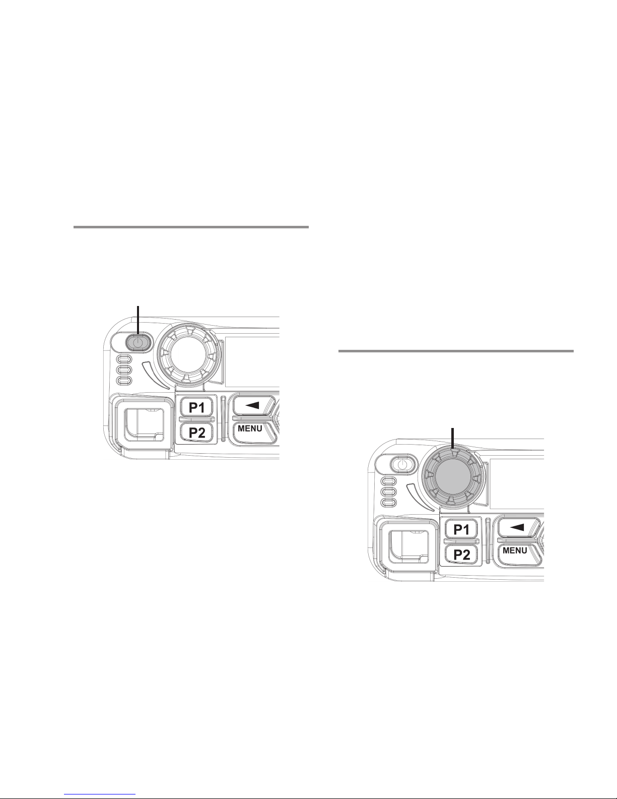
Powering Up the Radio
Press the On/Off Button briey.
The green LED blinks and the Home screen lights
up if the backlight setting is set to turn on automatically.
On/Off Button
Volume Knob
18
iDentifying raDio controls
Take a moment to review the following:
Radio Controls ............................................ page 18
Programmable Buttons ............................... page 19
Accessing the Programmed Functions ....... page 21
Push-To-Talk (PTT) Button ......................... page 22
Switching Between Conventional Analog
and Digital Mode......................................... page 23
iDentifying raDio controls
n
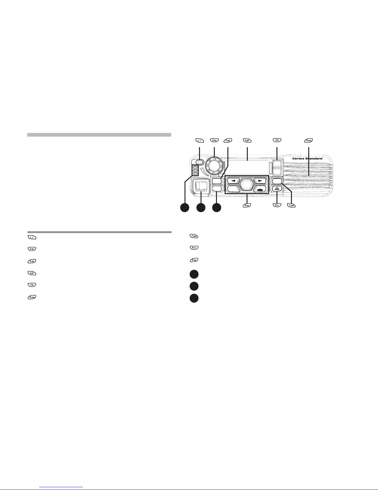
Radio Controls
: On/Off Button
: Volume Knob
: Front Button P1*
: Display
: Channel Rocker
: Speaker
: Front Button P3*
: Front Button r*
: Menu Navigation Buttons
10
: Front Button P2*
11
: Accessory Connector
12
: LED Indicator
* These buttons are programmable.
VXD-7200
CH+
MENU
BACK
ENTER
CH-
P3
P1
P2
101112

19
n
Programmable Buttons
Your dealer can program the programmable buttons as shortcuts to radio functions or up to a
maximum of six (6) preset channels/groups depending on the duration of a button press:
• Short press – Pres sin g and releasing rap idl y
(0.05 seconds).
• Long press – Pressing and holding for the programmed duration (between 1.00
second and 3.75 seconds).
• Hold down – Keeping the button pressed.
NOTE: The programmed duration of a button press
is applicable for all assignable radio/utility functions or settings. See Emergency
Operation on page 52 for more information
on the programmed duration of the Emer-
gency button.
1
Assignable Radio Functions
Contacts – Provides direct access to the Contacts
list.
Emergency – Depending on the programming, ini-
tiates or cancels an emergency alarm or call.
Ext PA On/Off – Toggles the audio routing between
the connected public address (PA) loudspeaker
amplier and the radio’s internal public address (PA)
system.
Manual Dial – Initiates a call by keying in any
subscriber ID. Only available with a keypad microphone.
Nuisance Channel Delete – Temporarily removes
an unwanted channel, except for the Selected
Channel, from the scan list. The Selected Channel
refers to the user’s selected zone/channel combination from which scan is initiated.
One Touch Access – Directly initiates a pre-
defined Private or Group Call, a Call Alert or a
Quick Text message.
PA On/Off – Toggles the audio’s internal public ad-
dress (PA) system on or off.
Permanent Monitor – Monitors a selected channel
for all radio trafc until function is disabled.
Privacy – Toggles privacy on or off.
Radio Check – Determines if a radio is active in
a system.
iDentifying raDio controls

20
Radio Enable – Allows a target radio to be re-
motely enabled.
Radio Disable – Allows a target radio to be re-
motely disabled.
Remote Monitor – Turns on the microphone of a
target radio without it giving any indicators.
Repeater/Talkaround – Toggles between using a
repeater and communicating directly with another
radio.
Scan – Toggles scan on or off.
Site Lock On/Off – Toggles the automatic site
roam on or off.
Text Message – Selects the text message
menu.
Voice Operating Transmission (VOX) – Toggles
VOX on or off.
Zone – Allows selection from a list of zones.
1
Assignable Settings or Utility Functions
All Tones/Alerts – Toggles all tones and alerts on
or off.
Backlight – Toggles display backlight on or off.
Horns/Lights – Toggles horns and lights feature
on or off.
Power Level – Toggles transmit power level be-
tween high and low.
Squelch – Toggles squelch level between nor-
mal and tight.
iDentifying raDio controls
21
n
Accessing the Programmed Functions
You can access various radio functions through
one of the following ways:
• A short or long press of the relevant program-
mable buttons.
OR
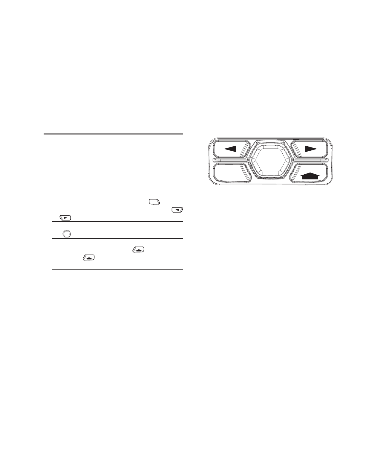
• Use the Menu Navigation Buttons as follows:
1 To access the menu, press the
MENU
button.
Press the appropriate Menu Scroll button
(
or
)
to access the menu functions.
2 To select a function or enter a sub-menu, press
the
ENTER
button.
3 To go back one menu level, or to return to the
previous screen, press the
BACK
button. Long
press the
BACK
button to return to the Home
screen.
NOTE: Your radio automatically exits the menu af-
ter a period of inactivity and returns to your
Home screen.
iDentifying raDio controls
MENU
BACK
ENTER
22
n
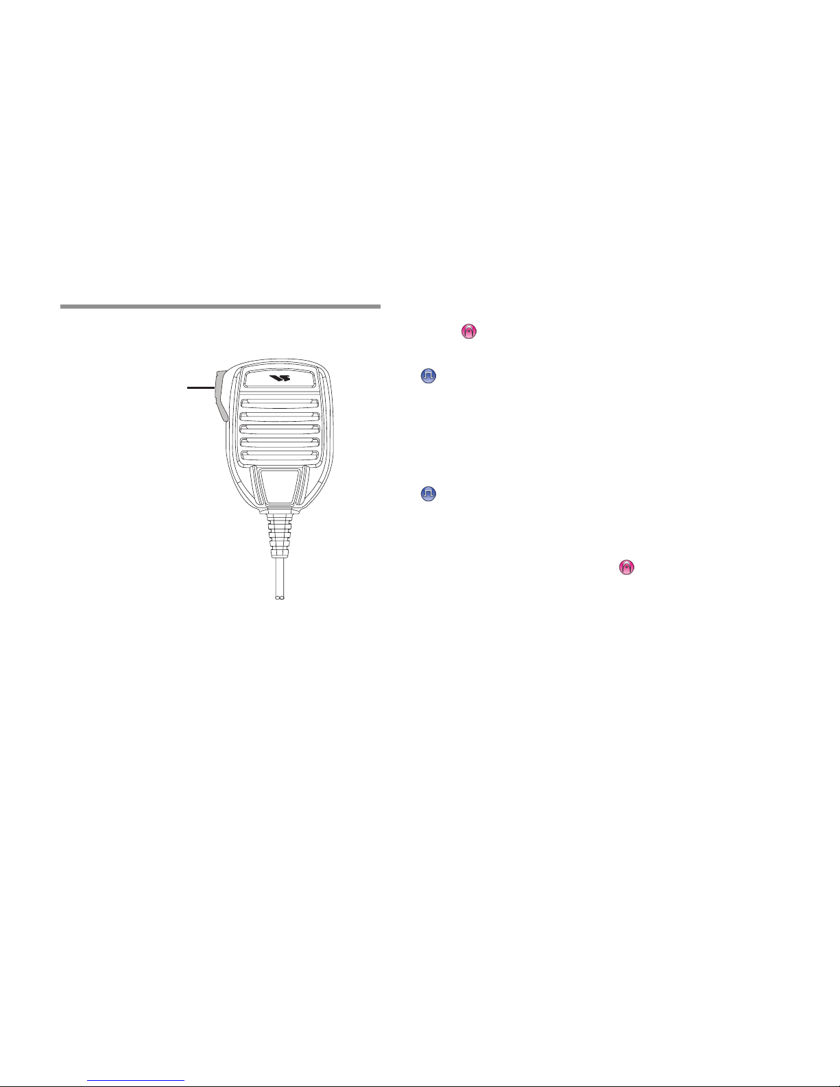
Push-To-Talk (PTT) Button
The PTT button on the side of the microphone
serves two basic purposes:
• While a call is in progress, the PTT button al-
lows the radio to transmit to other radios in the
call.
Press and hold down PTT button to talk. Re-
lease the PTT button to listen.
The microphone is activated when the PTT but-
ton is pressed.
• While a call is not in progress, the PTT button is
used to make a new call (see Making a Radio
Call on page 32).
If the Talk Permit Tone (see Turning the Talk Permit Tone On or Off on page 77) or the PTT Sid-
etone is enabled, wait until the short alert tone
ends before talking.
During a call, if the Channel Free Indication
feature is enabled on your radio (programmed
by your dealer), you will hear a short alert tone
the moment the target radio (the radio that is
receiving your call) releases the PTT button, indicating the channel is free for you to respond.
You will also hear the Channel Free Indication
tone if your call is interrupted, for example when
the radio receives an Emergency Call.
You can turn off the Channel Free Indication
tone or the PTT Sidetone by disabling all
radio tones and alerts (see Turning the Radio
Tones/Alerts On or Off on page 76).
iDentifying raDio controls
PTT Button

23
n
Switching Between Conventional Analog
and Digital Mode
Each channel in your radio can be congured as a
conventional analog or conventional digital channel. Use the Channel Rocker to switch between
an analog or a digital channel.
When switching from digital to analog mode, certain features are unavailable. Icons for the digital
features (such as Messages) reect this change by
appearing ‘grayed out’.
Disabled features are hidden in the menu.
Your radio also has features available in both analog and digital mode. However, the minor differences in the way each feature works does NOT affect
the performance of your radio.
NOTE: Your radio also switches between digital
and analog modes during a dual mode
scan (see Scan on page 44).
iDentifying raDio controls
Channel Rocker
24
iDentifying status inDicators
Your radio indicates its operational status through
the following:
Display Icons .............................................. page 24
Call Icons .................................................... page 25
Sent Item Icons........................................... page 26
LED Indicator .............................................. page 26
Audio Tones ................................................ page 27
Indicator Tones ........................................... page 27
n
Display Icons
The liquid crystal display (LCD) of your radio shows
radio status, text entries, and menu entries.
The following are icons that appear on the radio’s
display.
Rec eive d S igna l Str engt h Ind icat or
(
RSSI
)
The number of bars displayed represents
the radio signal strength. Four bars indicate
the strongest signal. This icon is only displayed while receiving.
Monitor
Selected channel is being monitored.
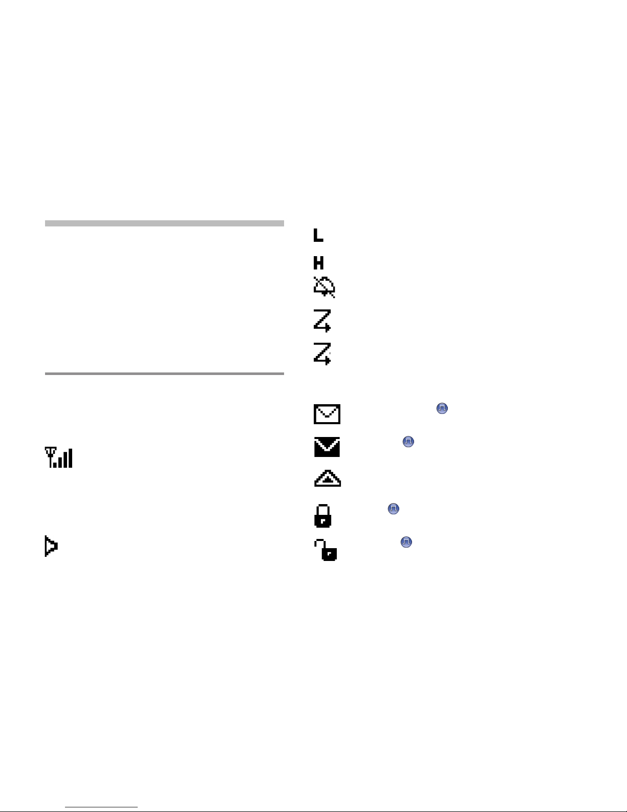
Power Level
Radio is set at Low power.
or
Radio is set at High power.
Tones Disable
Tones are turned off.
Scan
Scan feature is enabled.
Priority Scan
Radio detects activity on channel/group
designated as Priority 1 (if “
§
”
is blinking) or
Priority 2 (if “
§
”
is steady).
Unread Message
User has unread message(s) in the Inbox.
Inbox Full
User’s Inbox is full.
Emergency
Radio is in Emergency mode.
Secure
The Privacy feature is enabled.
Unsecure
The Privacy feature is disabled.
iDentifying status inDicators
 Loading...