

Vertex Standard VX-900, VX-900U Operating Manual
VX-900
Operating Manual
VERTEX STANDARD CO., LTD.
4-8-8 Nakameguro, Meguro-Ku, Tokyo 153-8644, Japan
VERTEX STANDARD
US Headquarters
17210 Edwards Rd., Cerritos, CA 90703, U.S.A.
International Division
8350 N.W. 52nd Terrace, Suite 201, Miami, FL 33166, U.S.A.
YAESU EUROPE B.V.
P.O. Box 75525, 1118 ZN Schiphol, The Netherlands
YAESU UK LTD.
Unit 12, Sun Valley Business Park, Winnall Close
Winchester, Hampshire, SO23 0LB, U.K.
YAESU GERMANY GmbH
Am Kronberger Hang 2, D-65824 Schwalbach, Germany
VERTEX STANDARD HK LTD.
Unit 5, 20/F., Seaview Centre, 139-141 Hoi Bun Road,
Kwun Tong, Kowloon, Hong Kong

Contents
Warning! FCC RF Exposure Compliance.....................................................................................................1
Controls & Connectors ...................................................................................................................................2
Before You Begin .............................................................................................................................................4
Battery Pack Installation and Removal ........................................................................................................4
Low Battery Indication.................................................................................................................................4
Operation..........................................................................................................................................................5
Preliminary Steps..........................................................................................................................................5
Operation Quick Start...................................................................................................................................5
Advanced Operation........................................................................................................................................8
Soft key and TOGGLE switch Functions.....................................................................................................8
ARTS (Auto Range Transpond System).....................................................................................................15
DTMF Paging System ................................................................................................................................15
Understanding Radio Waves ........................................................................................................................16
Accessories & Options...................................................................................................................................17

WARNING! FCC RF EXPOSURE COMPLIANCE
FCC RF Exposure Compliance Requirements for Occupational Use Only:
This Radio has been tested and complies with the Federal Communications Commission (FCC) RF exposure limits for
Occupational Use/Controlled exposure environment. In addition, it complies with the following Standards and Guidelines:
FCC 96-326, Guidelines for Evaluating the Environmental Effects of Radio-Frequency Radiation.
r
FCC OET Bulletin 65 Edition 97-01 (1997) Supplement C, Evaluating Compliance with FCC Guidelines for Human
r
Exposure to Radio Frequency Electromagnetic Fields.
ANSI/IEEE C95.1-1992, IEEE Standard for Safety Levels with Respect to Human Exposure to Radio Frequency Elec-
r
tromagnetic Fields, 3 kHz to 300 GHz.
ANSI/IEEE C95.3-1992, IEEE Recommended Practice for the Measurement of Potentially Hazardous Electromag-
r
netic Fields - RF and Microwave.
This radio is NOT approved for use by the general population in an uncontrolled exposure environment. This
¦
radio is restricted to occupational use, work related operations only where the radio operator must have the
knowledge to control his or her RF exposure conditions.
The radio is transmitting when the red LED on the top of the radio is illuminated. You can cause the radio to
¦
transmit by pressing the P-T-T button.
When transmitting, hold the radio in a vertical position with its microphone 2 inches (5 cm) away from your
¦
mouth and keep the antenna at least 2 inches (5 cm) away from your head and body.
Always use Vertex Standard authorized accessories.
¦
Important Notice for North American Users Regarding 406 MHz Guard Band
The U.S. Coast Guard and National Oceanographic and Atmospheric Administration have requested the cooperation of
the U.S. Federal Communications Commission in preserving the integrity of the protected frequency range 406.0 to
406.1 MHz, which is reserved for use by distress beacons. Do not attempt to program this apparatus, under any circumstances, for operation in the frequency range 406.0 - 406.1 MHz if the apparatus is to be used in or near North America.
Warning - Frequency band 406 - 406.1 MHz is reserved for use ONLY as a distress beacon by the US Coast
Guard and NOAA. Under no circumstance should this frequency band be part of the preprogrammed operating frequencies of this radio.
VX-900U OPERATING MANUAL
1
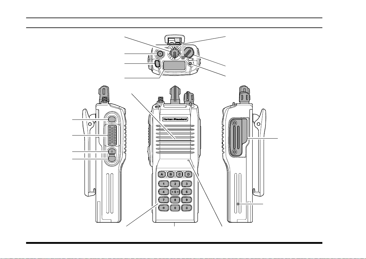
CONTROLS & CONNECTORS
LCD (Liquid Crystal Display
SIDE SEL Key
PTT Switch
MONITOR Button
LAMP Button
CH (Channel) Selector
Antenna Jack
TOP SEL Key
)
Speaker
LED Indicator
Steady Green: Signaling off
Blinking Green: Busy Channel (or SQL off)
Steady Red: Transmission in Progress
Blinking Red: Battery voltage is low
VOL/PWR Knob
TOGGLE Switch
MIC/SP Jack
(
External MIC/
)
SP
Sub Microphone
(
Noise Canceling Microphone
)
2
16-Button DTMF Keypad
(
16-key version only
)
Battery Pack Latch
Main Microphone
VX-900U OPERATING MANUAL
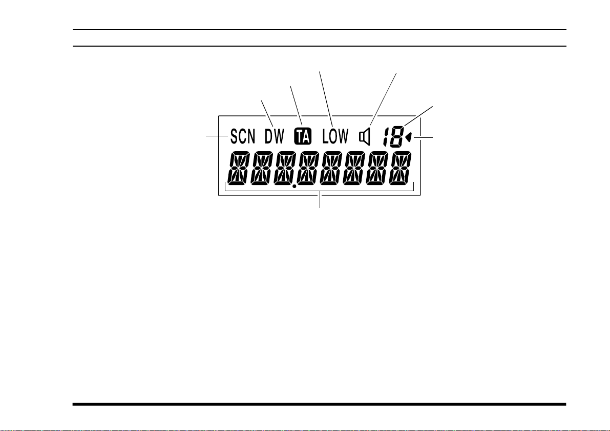
LCD ICONS & INDICATORS
Low Transmit Power Mode On
This Channel on “DUAL WATCH” List
This Channel on “SCAN” List
Talk-Around Mode
8 Character Alpha-numeric Invertible Display
Receive Monitor
Steady On: Signal off
Blinking: Busy Channel (or SQL off)
Channel Group Number
(
“01” ~ “19” and “0”
Group Scan Enabled
(this group)
)
VX-900U OPERATING MANUAL
3
BEFORE YOU BEGIN
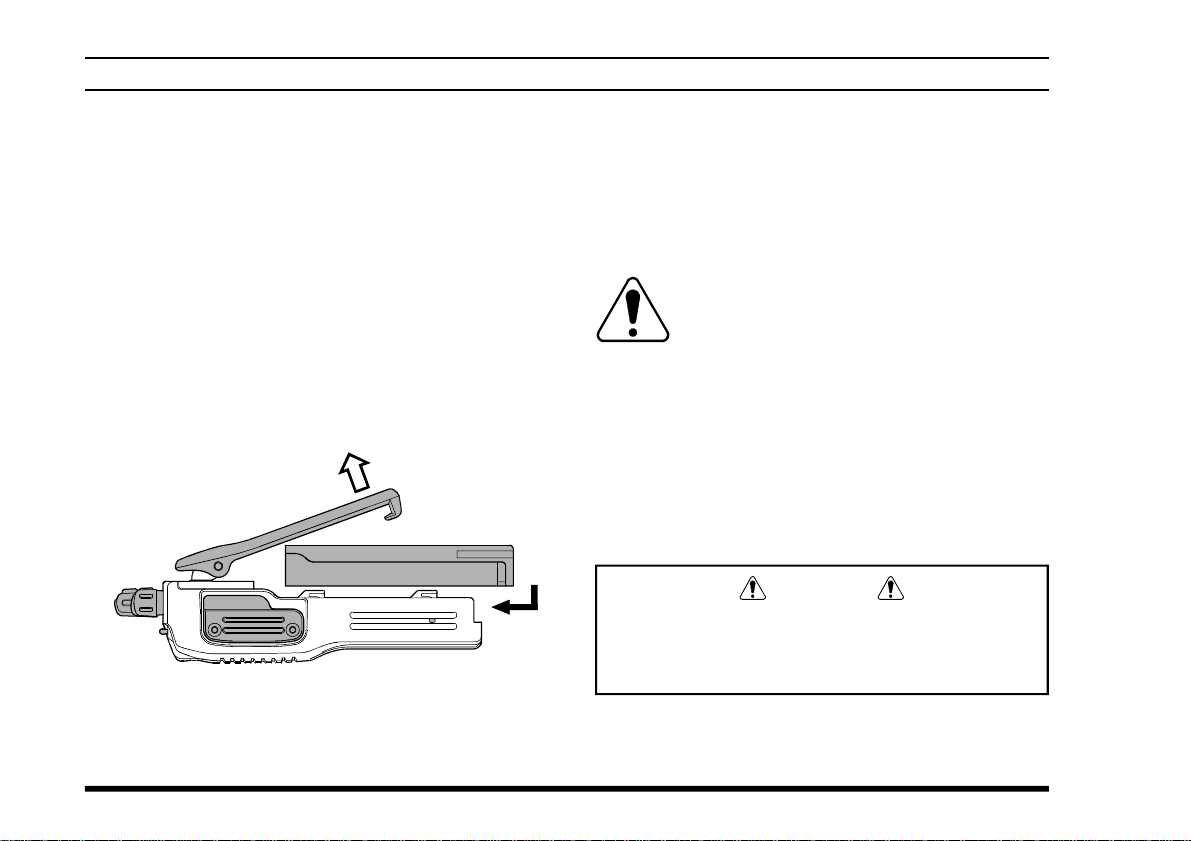
Battery Pack Installation and Removal
To install the battery, hold the transceiver with
r
your left hand, so your palm is over the speaker
and your thumb is on the top of the belt clip. Carefully mate the battery’s four insertion slots with
their corresponding alignment tabs on the transceiver case, while tilting the Belt Clip outward.
Proper alignment occurs with the battery pack
offset about 1/2 inch from the top edge of the
battery compartment.
Guide the pack on to the tabs with a slight inward
r
pressure, then slide the battery pack upward, until it locks in place with a “Click.”
Tilt the Belt Clip
Insert the Battery Pack
To remove the battery, turn the radio off and re-
r
move any protective cases. Slide the Battery
Pack Latch on the bottom of the radio toward
the front panel while sliding the battery down
about 1/2 inch. Then lift the battery out from the
radio while unfolding the Belt Clip.
Do not attempt to open any of the rechargeable Lithium-Ion packs, as they could explode if accidentally short-circuited.
Low Battery Indication
As the battery discharges during use, the voltage
gradually becomes lower. When the battery voltage
reaches 6.0 volts, it is time to substitute a freshly
charged battery and recharge the depleted pack. The
LED indicator on the top of the radio will blink red
when the battery voltage is low (6 Volts or lower).
Caution
Danger of explosion if battery is replaced with
an incorrect battery. Replace only with the same
or equivalent type.
4
VX-900U OPERATING MANUAL
OPERATION
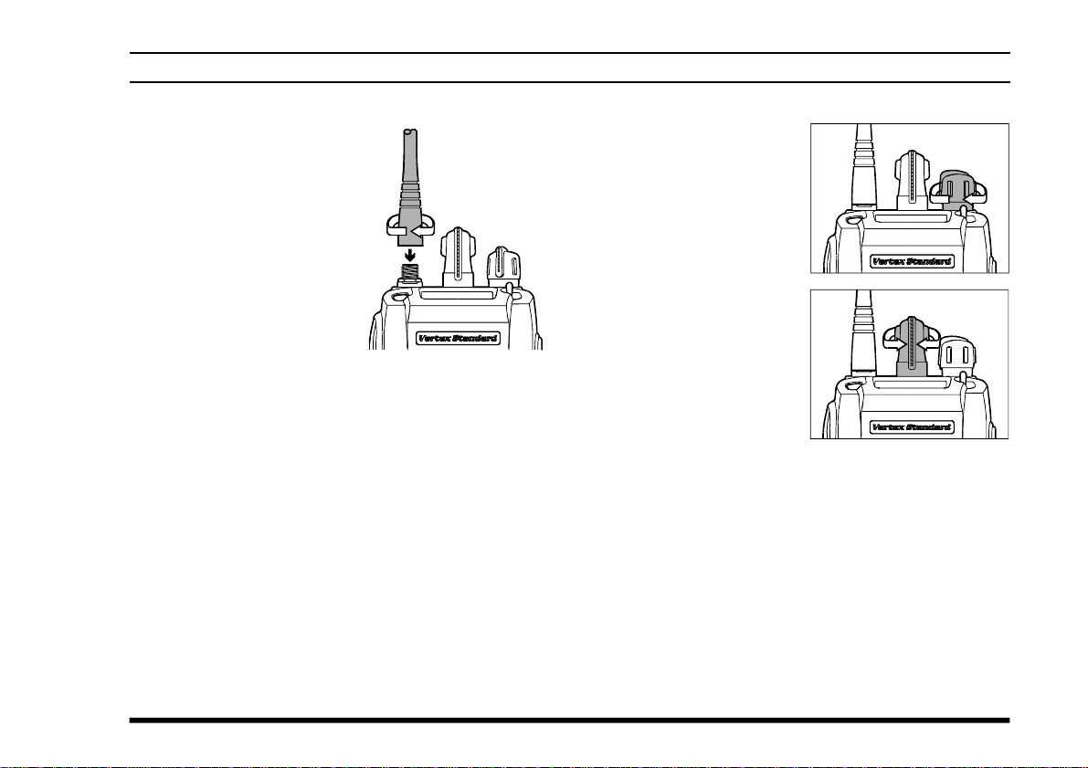
Preliminary Steps
Install a charged battery
r
pack onto the transceiver,
as described previously.
Screw the supplied an-
r
tenna onto the Antenna
jack. Never attempt to operate this transceiver
without an antenna connected.
If you have a Speaker/Mi-
r
crophone, we recommend that it not be connected
until you are familiar with the basic operation of
the VX-900.
VX-900U OPERATING MANUAL
Quick Start
Turn the top panel’s
r
VOL/PWR knob
clockwise to turn on
the radio on.
Turn the top panel’s CH
r
selector knob to choose
the desired operating
channel. A channel
name will appear on the
LCD. If you want to select the operating channel from a different Memory Channel Group, press
the Soft key (assigned to the Memory Group Up or
Down function) to select the Memory Channel
Group you want before selecting the operating channel. A Group name will appear on the LCD whenever the Soft key is pressed.
Note: Some models are programmed so that the
operating channels are selected by the Soft key
and the memory channel group is selected by the
CH selector knob. For further details, contact your
VERTEX STANDARD dealer.
5
 Loading...