

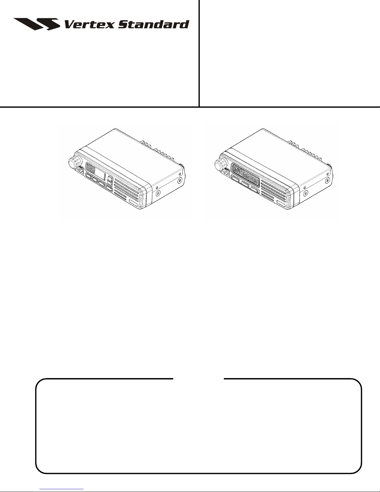
VHF Land Mobile Transceiver
VX-2000V
Service Manual
©2003 VERTEX STANDARD CO., LTD. E095390A
VERTEX STANDARD CO., LTD.
4-8-8 Nakameguro, Meguro-Ku, Tokyo 153-8644, Japan
VERTEX STANDARD
US Headquarters
10900 Walker Street, Cypress, CA 90630, U.S.A.
International Division
8350 N.W. 52nd Terrace, Suite 201, Miami, FL 33166, U.S.A.
YAESU EUROPE B.V.
P.O. Box 75525, 1118 ZN Schiphol, The Netherlands
YAESU UK LTD.
Unit 12, Sun Valley Business Park, Winnall Close
Winchester, Hampshire, SO23 0LB, U.K.
VERTEX STANDARD HK LTD.
Unit 5, 20/F., Seaview Centre, 139-141 Hoi Bun Road,
Kwun Tong, Kowloon, Hong Kong
40 channel version 4 channel version
Introduction
This manual provides technical information necessary for servicing the VX-2000V VHF Land Mobile transceiver.
The VX-2000V is carefully designed to allow the knowledgeable operator to make nearly all adjustments required for
various station conditions, modes and operator preferences simply from the controls on the panels, without opening the
case of the transceiver. The VX-2000V Operating Manual describes these adjustments, plus certain internal settings.
Servicing this equipment requires expertise in handling surface mount chip components. Attempts by non-qualified
persons to service this equipment may result in permanent damage not covered by warranty.
For the major circuit boards, each side of the board is identified by the type of the majority of components installed on
that side.
In most cases one side has only chip components, and the other has either a mixture of both chip and lead components
(trimmers, coils, electrolytic capacitors, packaged ICs, etc.), or lead components only.
While we believe the technical information in this manual is correct, Vertex Standard assumes no liability for damage
that may occur as a result of typographical or other errors that may be present. Your cooperation in pointing out any
inconsistencies in the technical information would be appreciated. Vertex Standard reserves the right to make changes in
this transceiver and the alignment procedures, in the interest of technological improvement, without notification of the
owners.
Contents
Operating Manual Reprint............................ 2
Specifications................................................... 7
Exploded View & Miscellaneous Parts....... 8
Block Diagram ................................................. 9
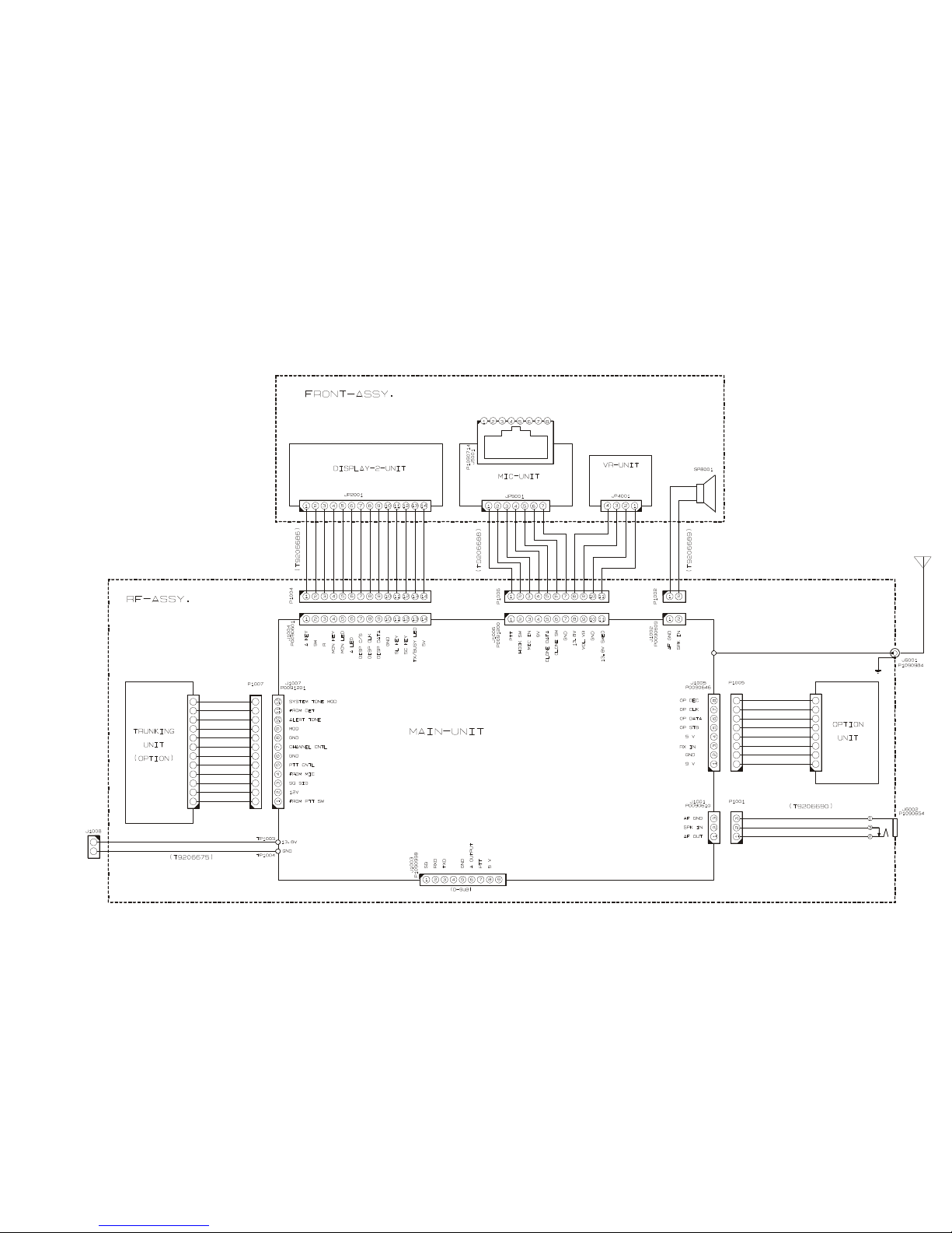
Interconnection Diagram............................. 13
Circuit Description ...................................... 15
Alignment....................................................... 19
Board Unit (
MAIN Unit ............................................................... 23
DISPLAY-1 Unit ...................................................... 49
DISPLAY-2 Unit ...................................................... 53
VR Unit ..................................................................... 57
MIC Unit .................................................................. 58
Schematics, Layouts & Parts
)
1
Operating Manual Reprint
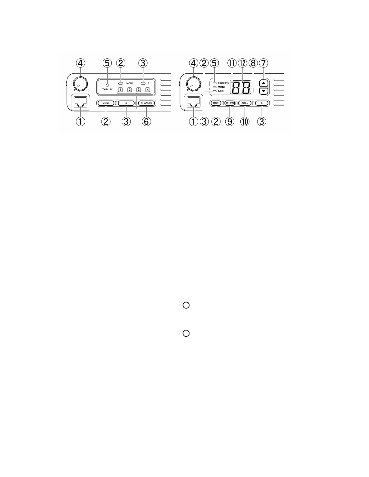
CONTROLS & CONNECTORS
40 channel version4 channel version
Microphone Jack
À
Connect the microphone plug to this jack.
MONI Button & Indicator
Á
This button selects the “squelch” (receiver mute) mode.
When the yellow indicator is off, “tone” or “coded” squelch
is active. When the indicator glows steadily, only “noise
squelch” is active, and any signal present on the channel
will be heard. When the indicator is blinking, the squelch is
disabled, and background noise will be heard if no signal is
present.
A Button & Indicator
Â
This button is provided for an ACCESSORY function such as
HIGH/LOW POWER selection, “TALK-AROUND”, or “CALL
ALERT” functions. The green “A” indicator will be illumi-
nated when this function is active.
VOLUME and POWER ON/OFF Knob
Ã
This knob adjusts the receiver volume, and turns the radio
off when turned all the way to the left into the click-stop.
TX/BUSY Indicator Lamp
Ä
This lamp blinks red when the channel is busy, and glows
steadily red during transmission. Do not transmit when this
indicator is blinking, as a courtesy to other users of the channel.
The following item is unique to the 4-channel
radio versions:
CHANNEL Numbered Indicators & Button
Å
Press the CHANNEL button to select the operating channel; the channel number currently in use will light up on the
display panel.
The following items are unique to the 40-channel
radio versions:
CHANNEL Selector Buttons (p) and (q)
Æ
Push one of these keys to select the operating channel, as
shown on the display.
Numeric Channel Display
Ç
This display area shows the channel number and prioritychannel/scan status.
SEL/PRI Button
È
This button is used to select a channel for “Priority” monitoring, and is used together with the SCAN button to select
the desired scanning mode.
SCAN Button
É
This button is used to activate scanning, to select or remove
channels on the scanning list, and (together with the SEL/
PRI button) to select scanning mode.
P Indicator
11
This small dot indicates Priority Channel status (described
later).
E Indicator
12
This small dot indicates Scanning on/off status (described
later).
2
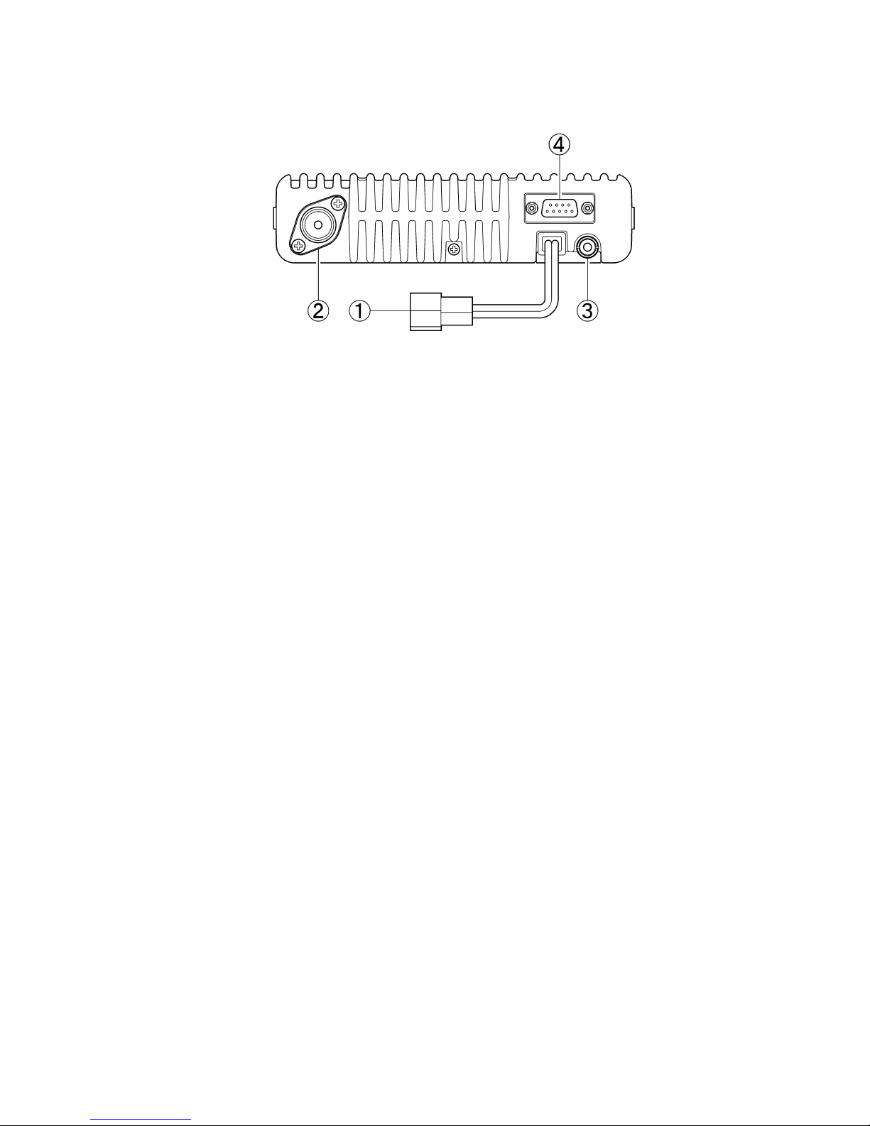
REAR (Heatsink)
13.6V DC Cable Pigtail w/Connector
À
The supplied DC power cable must be affixed to this 2-pin
connector.
Antenna Socket
Á
The 50-ohm coaxial feedline to the antenna must be connected here, using a “UHF” type (PL-259) plug.
Operating Manual Reprint
External Speaker Jack
Â
An external loudspeaker may be connected to this 2-contact, 3.5-mm miniature phone jack.
DSUB 9-Pin Data Connector
Ã
External Transmit Audio input, PTT (Push To Talk),
Squelch, and Receive Audio output signals may be obtained
from this connector for use with accessories such as a data
transmission/reception modem, etc.
3

Operating Manual Reprint
OPERATION
Power ON/OFF
Turn the VOLUME/POWER knob clockwise to turn on the radio. The active display and channel indicators will become illuminated, indicating the status of the radio. The channel indicated
will be the same one on which you were operating when the radio was last turned off.
Setting the Channel
In 4-channel versions, press the CHANNEL button to change
channels.
In 40-channel versions, the display will show either a channel
number or a Scan Mode indicator (Sc, Ur, SP or UP). If a Scan
Mode indicator is displayed, press the SCAN button momentarily so that a channel number is displayed; then press either the
UP (p) or DOWN (q) button to change channels.
Setting the Volume
Rotate the VOLUME/POWER knob clockwise to increase the
volume level. If no signal is present on which to adjust the volume level, push and hold in the MONI button for two seconds;
the yellow “MONI” indicator will blink, and either background
noise or a voice signal will be heard. You may now adjust the
VOLUME/POWER knob for a comfortable listening level.
When you are done, press the MONI button momentarily to return to silent monitoring.
Transmitting
To transmit, wait until the “TX/BUSY” indicator is off (this indicates that the channel is not in use). Then press the PTT (Push-
To-Talk) switch on the side of the microphone; while holding in
the PTT switch, speak in a normal voice level across the face of
the microphone. During transmission, the red “TX/BUSY” indicator will glow steadily. When you are done transmitting, release the PTT switch; the VX-2000 will revert to the “receive”
mode.
The remaining instructions apply to 40-channel trans-
Scanning
To activate scanning on your radio, first place the microphone in
its hanger. Now press the SCAN button momentarily. The radio
will scan in one of four available Scan Modes (detailed below),
and will halt when a signal is received which contains the correct
code to open your squelch. Scanning will resume automatically
either after a preset interval of a few seconds, or after the other
station stops transmitting (depending on how your radio was programmed).
The four Scan Modes, and their corresponding displays, are:
Display Scanning function
Sc Scan all channels
Ur Scan only user-selected channels
SP Monitor one channel plus dealer-designated Priority Channel(s)
UP Scan user-selected channels plus uer-designated Priority Channel(s)
The user-selected channels for the Ur and UP Scan Modes are
ones you can set up yourself, as described at the right. The
“Priority” channels are those on which signals will take priority over signals received on other channels; that is, if a signal
appears on a Priority Channel while another appears on a nonpriority channel, the Priority Channel signal will be heard, and
not the other.
Up to two of the installed channels may be designated by your
Dealer as pre-programmed Priority Channels for the SP mode
(the radio will not indicate which they are), and you can additionally program any two channels as “User Priorities” for the
UP mode. In the SP mode, the non-priority channel will be the
last one displayed.
When a Scan Mode is displayed, you can select another by pressing the SEL/PRI button repeatedly (the display will cycle through
the above selections). Note that the radio will not scan if the
microphone is not in its hanger.
ceiver versions only
Special Transmitter Functions
If your VX-2000 is programmed for Busy Channel LockOut, the transmitter will not activate when the PTT switch is
pressed unless the “TX/BUSY” indicator is off (so as to prevent interference to other users of the same channel).
If the selected channel has been programmed for Automatic
Time-Out, you must limit the length of your transmissions.
While transmitting with this feature activated, a “beep” will
sound ten seconds before the timer expires, and then another
“beep” sound as the timer expires: the “TX/BUSY” indicator will shut off, and transmission will cease. Release the
PTT switch, listen for a moment, then press PTT again to
resume transmission. This feature prevents interference to
other users caused by a microphone which accidentally is
stuck in the “transmit” position (wedged between seats of a
car, etc.).
4

Operating Manual Reprint
USER PROGRAMMABLE CHANNEL SELECTIONS
You can program a list of channels to be scanned, and up to two
channels to be monitored on a “priority” basis. Your selections
will be maintained in memory until you change or delete them.
Setting of these channels involves two small “Dot” indicators at
the top of the channel display field. The Dot to the left of the first
digit is the “P” (Priority) indicator, while the Dot to the left of
the second digit is the “E” (Enable for Scanning) indicator.
To create or modify the Scan and Priority selections, first turn
the radio off. Now press and hold in the SCAN button while you
turn the transceiver back on; continue to hold the SCAN button
in for two seconds after the radio has come on, then you may
release it.
Now press the UP (p) or DOWN (q) button repeatedly, and
note whether or not the “E” (right dot) or “P” (left) dots appear
on any of your channels. If a dot appears by any channel, it means
that it has been designated as either a Scan-Enabled or Priority
channel, respectively.
To enable or disable a channel from the User Scan list, press the
SEL/PRI button momentarily. The “E” dot will appear or disappear, as appropriate.
To change the Priority Channels, first cancel both by selecting
either, and then pressing the SEL/PRI button momentarily. Now
select the channel you wish to designate as the 1st Priority Chan-
nel, and hold in the SEL/PRI button for 2 seconds, until a beep
sounds and the “P” indicator blinks. If you wish to designate a
2nd Priority Channel, move to that channel, and again hold in
the SEL/PRI button for 2 seconds; this time, the “P” indicator
will glow, but will not blink.
If you have deleted a channel from Priority status, you must reenable it for scanning if you want it to be included on your Scan
List. Press the SEL/PRI button momentarily to do this.
Coded Squelch - the MONI Button
Your transceiver may be programmed so that when the microphone is removed from its hanger, coded squelch is defeated, and you can hear any signal on the channel (the yellow “MONI” indicator will be lit). You can get the same
result, without lifting the microphone, by pressing the MONI
button momentarily. To avoid listening to unnecessary chatter, keep the microphone in its hanger, and press the MONI
button when necessary to turn the yellow indicator off (unless you want to listen to other calls on the channel).
Holding the MONI button in for two seconds defeats both
the coded squelch and noise squelch, so background noise
can be heard (the “MONI” indicator will blink in this case).
Press the MONI button momentarily to return the yellow
indicator to its previous state (either off or steadily on).
OPTIONAL ACCESSORIES
CE-20 Programming Software (for IBM PC/compatibles only)
VPL-1 Programming Cable
T9101411 Radio-to-Radio Cloning Connection Cable
FP-1025A Heavy-Duty (20A) AC Power Supply
MD-11A8J Desktop Microphone
MH-600D DTMF Back-lit Microphone w/Autodial
MLS-100 External Loudspeaker
LF-1 DC Line Filter
VTM-20 VX-Trunk II Trunking Mobile Logic Board
F2D-4A/B 2-Tone Decoder Unit
FTE-18 ANI Unit
5
Operating Manual Reprint
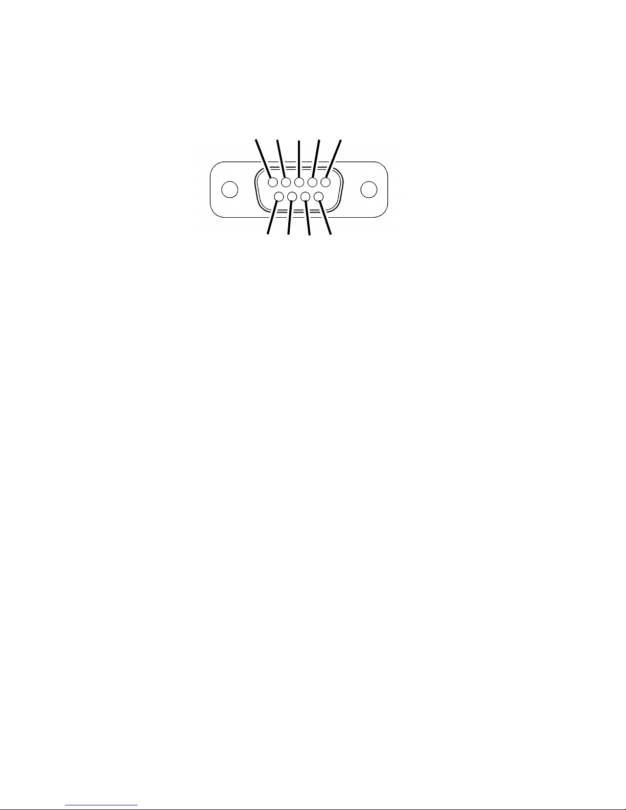
J1003 DSUB 9-Pin Data Connector Pin Assignment
ÃÄ Â Á À
È Ç Æ Å
À SQ: Squelch Signal Output
Carrier In: Active High (5 V / 47 kΩ)
Á RX_AUD_OUT: Received Audio Output (Two choices available)
Á-1 De-Empasized Audio Output: 100 mV / 10 kΩ
This output level's default state is fixed at the factory by
having no jumper at JP1003 and soldering the jumper at
JP1002 on the MAIN Unit.
Á-2 Flat / Unmuted Audio Output: 250 mV / 10 kΩ
(Unsolder the jumper at JP1002 and solder a jumper at JP1003
on the MAIN Unit to activate Á-2)
 EXT_MIC: External MIC Audio Input (Two choices available)
Â-1 Pre-Emphasized / IDC / Splatter Filtered Audio Input:
2.5 mV / 600 Ω
This input is fixed at the factory by attaching capacitor
C1254 across JP1005 and soldering a jumper at JP1004
on the MAIN Unit.
Â-2 Flat (Non-Pre-Emphasized) Audio Input: 650 mV / 10 kΩ
(Remove the jumper at JP1004 and solder a jumper across
JP1005 on the MAIN Unit to activate Â-2)
à Not Used
Ä GND: Ground
Å A_OUTPUT: Accessory Output (Two choices available)
Å-1 Not Used
This is the default setting at the factory (no jumper across
JP1001 on the MAIN Unit).
Å-2 Accessory Output: Open Collector Output
"A" Lamp ON: Low, "A" Lamp OFF: Open
Maximum voltage: 13.8 V, Maximum sink current 5 mA
(Solder a jumper at JP1001 on the MAIN Unit to activate Å-2)
Æ PTT: External PTT Signal input
GND: TX, Open: RX
Ç 5 V
Switched and regulated DC 5 V output for supplying
power to an accessory.
Maximum output current is 50 mA.
È Not Used
6

Specifications
General
Frequency Range (version): 134 ~160 or 148 ~ 174 MHz (VHF vers. A/C, respectively)
No. of Channels & Spacing: 4 or 40 channels 25-kHz, 12.5-kHz spacing
Modes of Emission: 16K0F3E ,11K0F3E
Frequency Stability: ±0.00025%
Antenna Requirements: 50 ohms, unbalanced (SO-239 socket)
Voltage Requirements: 11.8 V to 15.6 V DC, negative ground
Current Consumption (approx.): 250 mA Stby, 200 mA Rx, 6.5 A Tx
Operating Temperature Range: -30 °C to +60 °C (-22 °F to +140 °F)
Size (WHD, approx.): 160 × 40 × 105 mm (6¼ × 1½ × 4¼ inches)
Weight (approx.): 0.85 kg (1.9 lbs.)
Receiver
Receiver Circuit Type: Double-Conversion Superheterodyne
Intermediate Frequencies: 17.7 MHz , and 450 kHz (all models)
Sensitivity: 0.2/0.25 µV for 12-dB SINAD
0.3/0.35 µV for 20 dB NQ
Hum & Noise Ratio: Better than 45 dB for 25-kHz/step,
Better than 40 dB for 12.5-kHz/step
Adjacent Channel Selectivity: >70 dB for 25-kHz/step,
>60 dB for 12.5-kHz/step
Intermodulation Distortion: Better than 65 dB
Spurious Rejection: Better than 65 dB
External Audio Output Power: 5 watts into 4 ohms with <10% THD
Transmitter
Power Output: 25/5 watts (high/low, programmable)
Modulation Type/Deviation: Frequency Modulation, ±5 kHz (±2.5 kHz )
Hum & Noise Ratio: Better than 45 dB for 25-kHz/step,
Better than 40 dB for 12.5-kHz/step
Modulation Distortion: Less than 5%
Spurious Emissions: Better than 65 dB (below carrier)
Microphone Impedance: 600 ohms
Specifications are subject to change without notice or obligation.
7
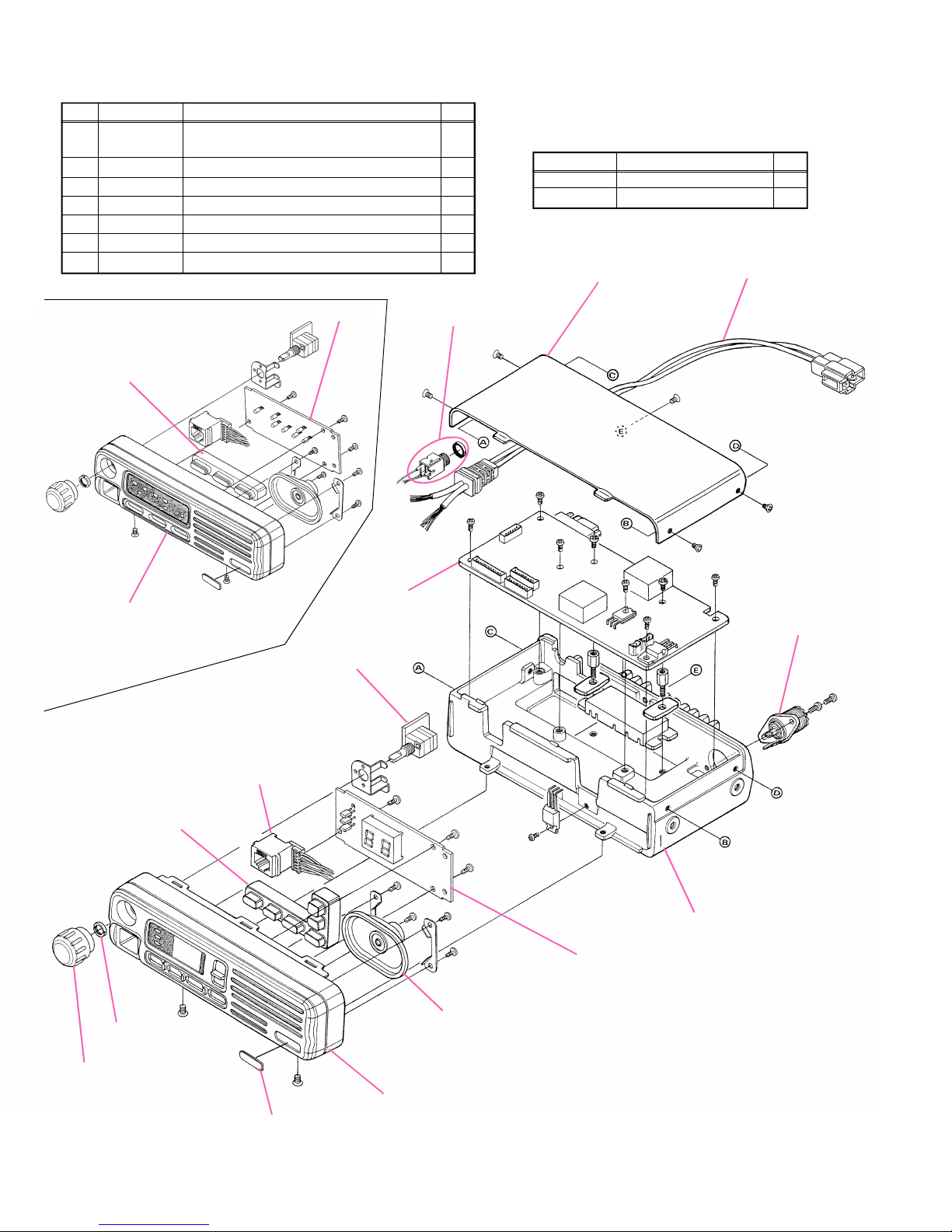
Exploded View & Miscellaneous Parts
VXSTD P/NREF.
U24208001 TAPTITE SCREW M2.6X8 (Lot. 1~5) 1
À
U20208001 BINDING HEAD SCREW M2.6X8 (Lot. 6~) 1
Á
U20306002 BINDING HEAD SCREW M3X6NI 4
U23205001 TAPTITE SCREW M2.6X5 4
Â
U23206001 TAPTITE SCREW M2.6X6 3
Ã
U24306002 TAPTITE SCREW M3X6NI 5
Ä
U31206007 OVAL HEAD SCREW M2.6X6B 7
Å
U24308001 TAPTITE SCREW M3X8 1
Æ
RA0034900
RUBBER KNOB (4CHANNEL)
CP6003001
PANEL-SUB A ASSY
Description
DISPLAY-1 Unit
MAIN Unit
Qty.
P1090654
CONNECTOR
Å
Ä
Å
VXSTD P/N
Q0000062 FUSE 10A 2
T9021810 DC CABLE 1
RA0060100
CASE
Description
T9206675
WIRE ASSY
Å
Ä
Ä
Á
Á
À
Æ
Å
Ä
P1090984
CONNECTOR
Qty.
Å
RA0015600
RUBBER KNOB (40 CHANNEL)
Å
R6054387B
SPECIAL NUT
RA001330A
KNOB
VR Unit
MIC Unit
Å
NAME PLATE
RA0013900 (EXPORT)
RA0014000 (VTX(USA))
Ã
Ã
Ã
Â
Â
Â
Â
M4090122
SPEAKER
CP6007001
PANEL-SUB B ASSY
Ä
RA0056000
RA005600A (Lot. 4~)
RA005600B (Lot. 6~)
DISPLAY-2 Unit
RA00560AB (NTL: Lot. 53~)
RA005600C (Lot. 68~)
RA00560AC (NTL: Lot. 68~)
CHASSIS
Non-designated parts are available
only as part of a designated assembly.
Á
Á
8
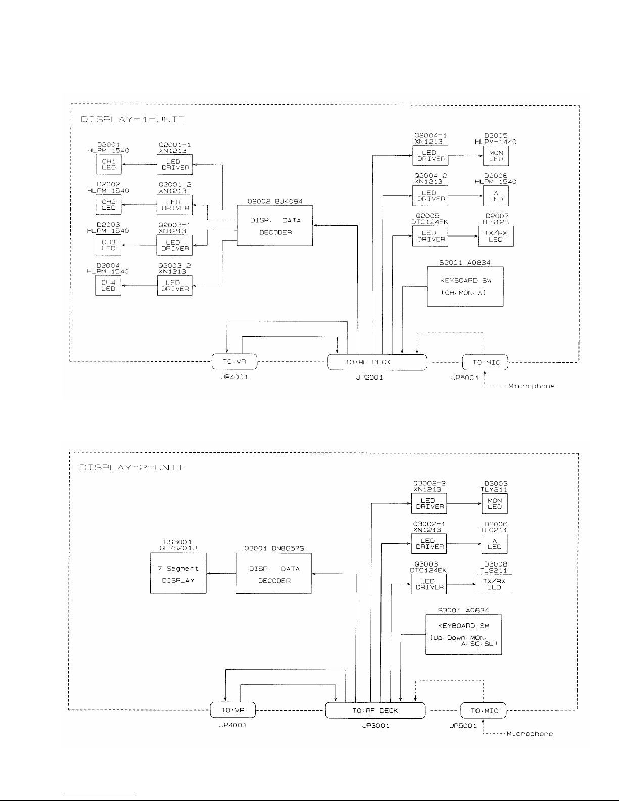
VX-2000V 4ch Front Panel Block Diagram
Block Diagram
VX-2000V 40ch Front Panel Block Diagram
9

Block Diagram
Note:
10
11
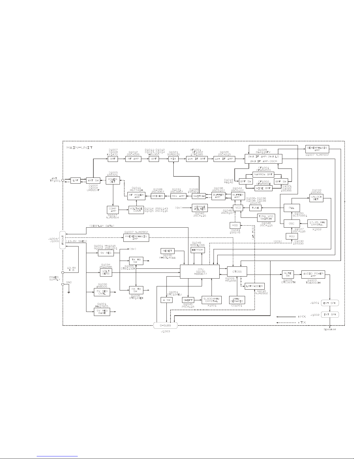
Block Diagram
VX-2000V Main Unit Block Diagram

12
Block Diagram
Note:
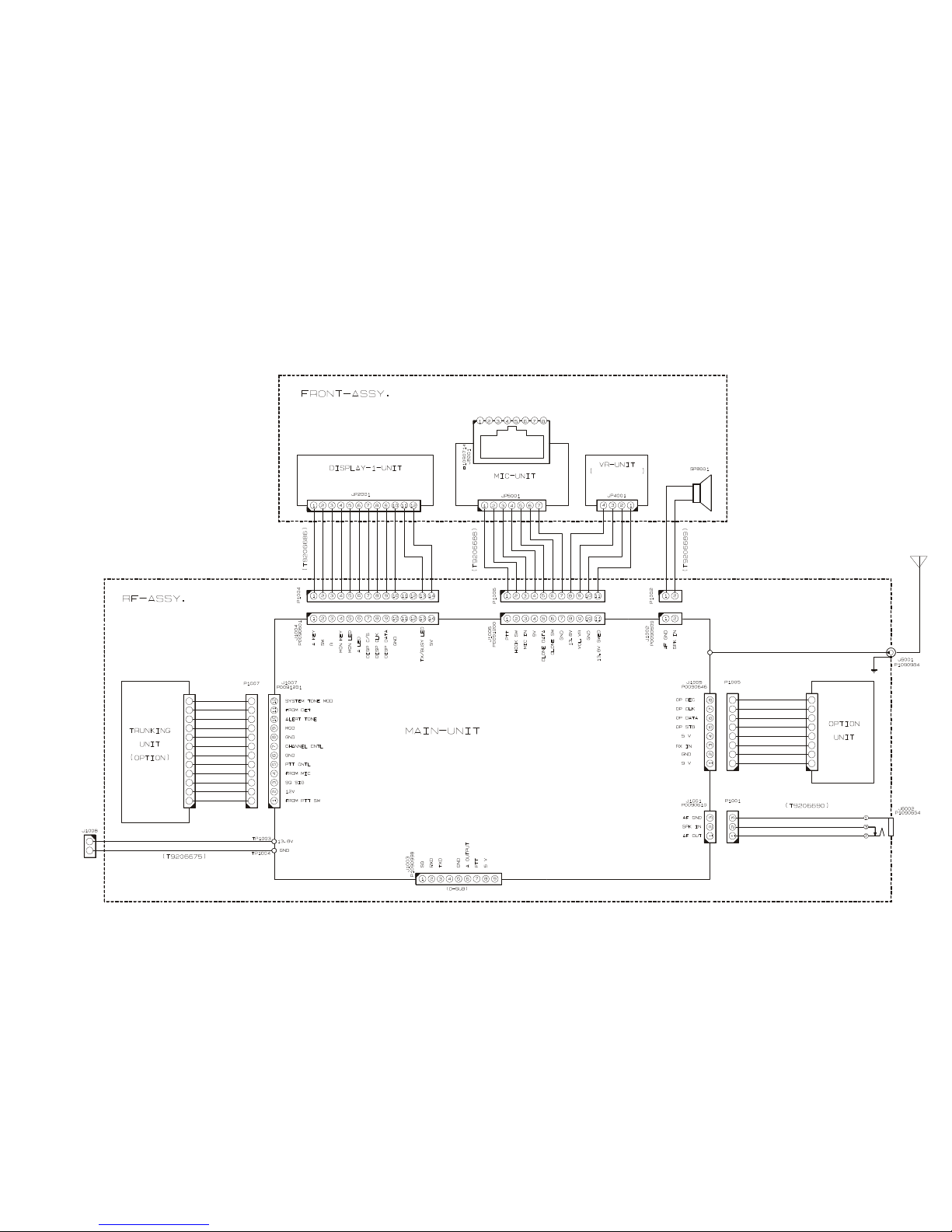
13
Interconnection Diagram
VX-2000V 4ch Front Interconnection Diagram
(T9206689A: Lot 7~)
14
Interconnection Diagram
VX-2000V 40ch Front Interconnection Diagram
(T9206689A: Lot 7~)

Circuit Description
Receive Signal Path
Incoming RF energy from the antenna jack is
delivered to the MAIN Unit, and passes through
a low-pass filter consisting of coils L1001, L1002,
L1004, and L1006, capacitors C1002, C1006,
C1009, C1017, C1019, C1022, C1041, and C1046,
and switching diodes D1002 (UM9957F) and
D1006 (RLS135), then delivered to the receiver
front end.
The RF energy then enters a varactor-tuned
bandpass filter, consisting of coils L1008, L1010,
L1011, L1013, L1014, T1001, and T1002, capaci-
tors C1045, C1052, C1054, C1057, C1058, C1069,
C1072, C1073, C1091, C1092, C1093, C1094,
C1096, C1097, C1100, C1101, C1105, C1106,
C1109, and C1110, plus diodes D1007/1008 (both
KV1470) and D1011~1014 (all HVU350). After
bandpass filtering, the in-band RF signals are
amplified by RF preamplifier Q1012 (2SC4226),
then delivered to the first mixer stage.
Buffered output from the VCO is amplified by
Q1038 (2SC5107), providing a pure local signal
between 130.3 and 156.3 MHz for injection to the
(CFWM450G) or CF1002 (CFWM450E) to strip
away unwanted mixer products, and then is ap-
plied to the limiter amplifier in Q1029, which re-
moves any amplitude variations in the 450 kHz IF.
Speech detection by CD1001 (CDBM450C24T)
is then performed, converting the second IF into
an audio signal.
Detected audio from Q1029 is amplified by
Q1017-1 (NJM2904V) and then applied to the de-
emphasis network, consisting of capacitors
C1084/C1089, resistors R1038/R1049, and Q1007-
4 (NJM2902V). The de-emphasized audio is then
applied to CTCSS subsystem IC Q1009
(MX165BDW), which contains the TX/RX audio
filter, CTCSS decoder and CTCSS encoder; if a
CTCSS tone is present on the incoming signal, it
is removed by the high-pass audio filter in Q1009.
The processed signal then passes through the
audio mute gate Q1008 (DTC323TK) and the
volume control, then enters the audio power
amplifier Q1003 (TDA2003H), which provides up
to 2 Watts of audio power to the external speak-
er jack.
first mixer, Q1021 (SGM2016). The resulting 17.7
MHz first IF then passes through monolithic crys-
tal filter XF1001, which strips away all but the
desired signal, and the signal is then amplified
by Q1026 (2SC4215Y). The amplified first IF sig-
nal is then applied to FM subsytem IC Q1029
(BA4116FV), which contains the second mixer,
a limiter amplifier, and a noise amplifier.
The second local oscillator signal is generated
by PLL reference/2nd LO transistor Q1047
(2SC4116GR), using the 17.25 MHz oscillator
crystal X1002 as a reference. This signal is mixed
with the 17.7 MHz local at Q1029, producing a
450 kHz second IF. The second IF signal then
passes through ceramic filter CF1001
Squelch Control
The squelch circuitry consists of a noise am-
plifier, bandpass filter, and noise detector with-
in Q1029, plus control circuitry within micropro-
cessor Q1039 (MB89677).
When no carrier is received, noise at the out-
put of the detector stage in Q1029 is amplified,
bandpass filtered, and detected by Q1029. The
resulting DC squelch control voltage is passed
to pin 33 of microprocessor Q1039. With no car-
rier being received, pin 33 remains low, signal-
ing pin 5 of Q1039 to keep the green "BUSY" LED
off, and simultaneously signaling pin 19 of Q1039
to command audio mute gate Q1008 to block re-
ceived audio.
15

Circuit Description
When a carrier appears at the discriminator,
noise is removed from the output, causing pin 33
of Q1039 to go "high," in turn causing the "BUSY"
LED and audio output lines to turn on. The mi-
croprocessor then checks for CTCSS information.
If CTCSS decode is not activated, or if CTCSS de-
code is activated and a signal carrying a matching
tone is received, the microprocessor allows audio
to pass through AF mute gate Q1008 and audio
amplifier Q1003 to the speaker.
Transmit Signal Path
Speech input from the microphone is delivered
to the MAIN Unit, where it passes through the preemphasis network (R1015 and C1031). The preemphasized speech signal proceeds through the
AF high-pass filter at Q1009, then is applied to
the IDC (Instantaneous Deviation Control) at
Q1016-3 (NJM2902V), with deviation level being
set by potentiometer VR1001. The audio then pass-
Automatic Transmitter Power Control
RF output from the final amplifier is sampled
by C1039 and C1051 and rectified by D1005
(1SS321). The resulting DC voltage is fed through
Automatic Power Controller Q1014 (2SB1143S),
Q1015 (2SC4116GR), and Q1017-2 to effect con-
trol of the gain of transmitter PA Q1011. The mi-
croprocessor, Q1039, issues commands for setting
"HIGH" or "LOW" power output.
Transmit Inhibit
When the transmit PLL is unlocked, pin 2 of
PLL IC Q1050 (SC370651F) goes to logic "low"
level. The resulting DC unlock control voltage
switches off the TX inhibit switch Q1022 (IMZ1),
which interrupts the supply voltage to the trans-
mitter PA, Q1011, thus disabling the transmitter.
Spurious Suppression
Generation of spurious products by the trans-
es to a splatter filter in sections 1 and 4 of Q1016,
which filters out high-frequency components
which could result in over-deviation.
The processed audio is mixed with the CTCSS
tone (if activated) generated by CTCSS subsystem
IC Q1009, then delivered to D1041 (1SV276) for
frequency modulation of the PLL carrier (at the
transmitting frequency) up to ±5 kHz from the
unmodulated carrier frequency.
The modulated signal from the VCO, Q1046
(2SC5107), is buffered by Q1038 and Q1044 (both
2SC5107). The low-level transmit signal is then
amplified by Q1028 and Q1031 (both 2SC3357),
then applied to the final amplifier, Q1101
(M67741H), providing 25 Watts of transmitter
power. The transmit signal then passes through
the antenna switch, D1003/D1004 (both
UM9957F) and low-pass filter (which suppress-
es harmonic spurious radiation) before delivery
to the antenna jack.
mitter is minimized by the fundamental carrier
frequency being equal to the final transmitting
frequency, modulated directly in the transmit
VCO. Additional harmonic suppression is pro-
vided by a low-pass filter consisting of L1001,
L1002, L1007, C1002, C1006, C1009, C1017,
C1019, C1036, and C1053, resulting in more than
60 dB of harmonic suppression prior to delivery
of the RF signal to the antenna jack.
PLL Frequency Synthesizer
The Phase-Locked Loop (PLL) circuitry on the
MAIN Unit includes VCO Q1046, VCO buffer
Q1044, and PLL subsystem IC Q1050, which in-
cludes a reference divider, serial-to-parallel data
latch, programmable divider, phase comparator,
and charge pump.
Stability of the reference oscillator, Q1047, is
maintained by a regulated 5 Volt supply, which
includes Q1001 (MM1216EN), Q1002
16

Circuit Description
(2SB1201STP-FA), Q1040 (2SC4116GR), and
D1029 (02CZ5.6Y), with temperature compen-
sation provided by thermistors TH1003/TH1004
and capacitors associated with the 17.25 MHz
reference crystal, X1002.
In the receive mode, VCO Q1046 oscillates
between 130.3 and 156.3 MHz, according to the
transceiver version and the programmed receiv-
ing frequency. The VCO output is buffered by
Q1044, and applied to the prescaler section of
Q1050. There the VCO signal is divided by 64 or
65, according to a control signal from the data
latch section of Q1050, before being applied to
the programmable divider section of Q1050. The
data latch section of Q1050 also receives serial
dividing data from the microprocessor, Q1039,
which causes the pre-divided VCO signal to be
quency of the VCO according to the phase dif-
ference between the signals derived from the
VCO and the crystal reference oscillator. The
VCO is thus phase-locked to the crystal reference
oscillator. The output of the VCO is then deliv-
ered to the first mixer via buffer amplifier Q1051.
For transmission, the VCO Q1046 oscillates
between 134 and 174 MHz, according to the mod-
el version and the programmed transmit frequen-
cy. The remainder of the PLL circuitry is shared
with the receiver section. However, the dividing
data from the microprocessor is such that the
VCO frequency is at the actual transmitting fre-
quency (rather than being offset by the IF, as in
the receiving case). Also, the VCO is modulated
by the speech audio applied to D1041 (1SV276),
as described previously.
further divided in the programmable divider sec-
tion, depending on the desired receive frequen-
cy, so as to produce either a 5.0 kHz or 6.25 kHz
derivative of the current VCO frequency.
Meanwhile, the reference divider section of
Q1050 divides the 17.25 MHz crystal reference
frequency by 3450 (or 2760) to produce the 5 kHz
(or 6.25 kHz) loop reference (respectively). The
5 kHz (or 6.25 kHz) signal from the programma-
ble divider (derived from the VCO) and that de-
rived from the reference oscillator are applied to
the phase detector section of Q1050, which pro-
duces a pulsed output with pulse duration de-
pending on the phase difference between these
input signals. The pulse train is filtered to DC
and returned to varactors D1035/D1036/D1038/
D1039 (all 1SV276).
Changes in the level of the DC voltage applied
Receive and transmit buses select which VCO
is made active via Q1048 (DTC124EU). FET
Q1043 (2SK880GR) buffers the VCV line for ap-
plication to the tracking bandpass filters in the
receiver front end.
Push-To-Talk (PTT) Transmit Activation
The PTT switch on the microphone is connect-
ed to pin 24 of microprocessor Q1039, such that
when the PTT switch is closed, pin 24 of Q1039
goes low . This signals the microprocessor's pin
35 to activate the TX/RX controller Q1004 (IMH6),
which in turn disables the receiver by disconnect-
ing the 9 Volt supply bus at Q1006 (DTB123EK)
to the receiver front end, FM subsystem IC, and
receiver VCO circuitry. At the same time, Q1005
(DTB123YK) activates the TX 9 Volt supply line
to enable the transmitter.
to the varactors affect the reactance in the tank
circuit of the VCO, changing the oscillating fre-
17

Circuit Description
Channel Selection & Display
(4-channel version)
The CHANNEL button on the front panel causes
microprocessor Q1039 to select the operating fre-
quency and CTCSS frequency data from serial
EEPROM Q1049 (BR93LC66RF). The operating
frequency data is in the form of PLL dividing
ratios, which are passed to the PLL IC on the
MAIN Unit via strobe, data, and clock outputs on
pins 43, 42, and 41 respectively. The channel digit
display data from the microprocessor is strobed
by pin 46 to display latch Q2002 (BU4094BCFV)
on the DISPLAY-1 Unit, which decodes the data
and drives the four channel LEDs and the func-
tion indicator LEDs.
Channel Selection & Display
(40-channel version)
The UP and DOWN buttons on the front panel
cause microprocessor Q1039 to select the oper-
ating frequency and CTCSS frequency data from
serial EEPROM Q1049. The operating frequency
data is in the form of PLL dividing ratios, which
are passed to the PLL IC on the MAIN Unit via
strobe, data, and clock outputs on pins 43, 42,
and 41 respectively. The channel digit display
data from the microprocessor is strobed by pin
46 to display latch Q3001 (DN8657S) on the DIS-
PLAY-2 Unit, which decodes the data and drives
the two 7-segment LEDs and the function indi-
cator LEDs.
18
 Loading...