

Vertex Standard VX-160V Service Manual
VHF FM Transceiver
VX-160V/-180V
Service Manual
©2005 VERTEX STANDARD CO., LTD. EC013N90B
VERTEX STANDARD CO., LTD.
4 8 8 Nakameguro, Meguro Ku, Tokyo 153 8644, Japan
VERTEX STANDARD
US Headquarters
10900 Walker Street, Cypress, CA 90630, U.S.A.
YAESU EUROPE B.V.
P.O. Box 75525, 1118 ZN Schiphol, The Netherlands
YAESU UK LTD.
Unit 12, Sun Valley Business Park, Winnall Close
Winchester, Hampshire, SO23 0LB, U.K.
VERTEX STANDARD HK LTD.
Unit 5, 20/F., Seaview Centre, 139 141 Hoi Bun Road,
Kwun Tong, Kowloon, Hong Kong
VX-160V VX-180V
Introduction
This manual provides technical information necessary for servicing the VX-160V and VX-180V FM Trans-
ceiver.
Servicing this equipment requires expertise in handling surface-mount chip components. Attempts by nonqualified persons to service this equipment may result in permanent damage not covered by the warranty,
and may be illegal in some countries.
Two PCB layout diagrams are provided for each double-sided circuit board in the transceiver. Each side of
is referred to by the type of the majority of components installed on that side (“leaded” or “chip-only”). In
most cases one side has only chip components, and the other has either a mixture of both chip and leaded
components (trimmers, coils, electrolytic capacitors, ICs, etc.), or leaded components only.
While we believe the technical information in this manual to be correct, VERTEX STANDARD assumes no
liability for damage that may occur as a result of typographical or other errors that may be present. Your
cooperation in pointing out any inconsistencies in the technical information would be appreciated.
Contents
Operating Manual Reprint............................ 2
Cloning .............................................................. 6
Specifications ................................................... 7
Exploded View & Miscellaneous Parts ...... 8
Block Diagram ................................................. 9
Circuit Description ................................11
Alignment .................................................13
Board Unit (
MAIN Unit................................................................ 17
Schematics, Layouts & Parts
)
Operating Manual Reprint
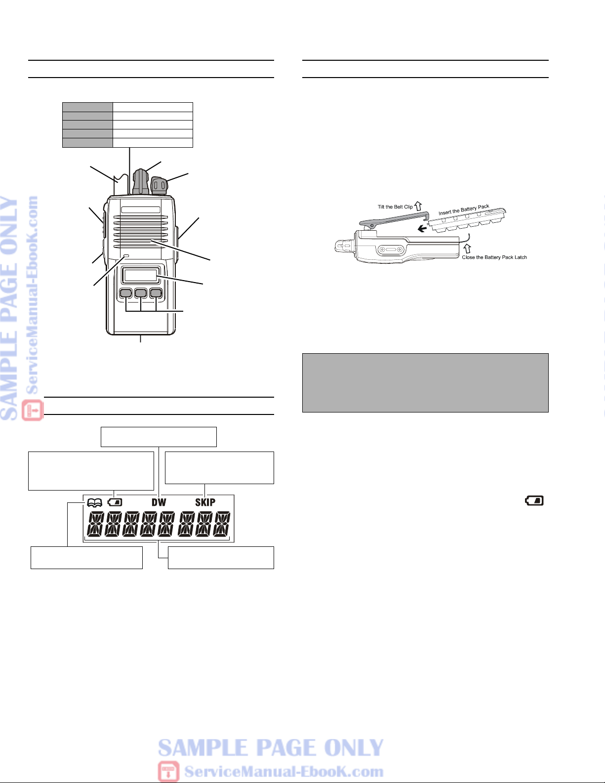
Controls & Connectors
LED Indicator
Glows Green Monitor on
Blinking Green Busy Channel (or SQL off)
Glows Red Transmitting
Blinking Red Battery Voltage is low
Blinking Yellow Receiving a Selective Call
Antenna
sh To Talk
PTT) Switch
nitor Button
Microphone
D s s d 0 ni & i s O l
isplay Icons & Indicators (VX-180 Only)
Dis s & di s 0 Onlisplay Icons & Indicators (VX-180 Only)
C e tt s c
t s C ectControls & Connectors
CH (Channel) Selector
VOL/PWR Knob
MIC/SP Jack
(
External Mic/Earphone
LCD (VX-180)
Soft KEY (VX-180)
Battery Pack Latch
Speaker
e or egf B i
Before You Begin
efor BeginBefore You Begin
Battery Pack Installation and Removal
U To install the battery, hold the transceiver with your
left hand, so your palm is over the speaker and your
thumb is on the top of the belt clip. Insert the battery
pack into the battery compartment on the back of the
radio while tilting the Belt Clip outward, then close
the Battery Pack Latch until it locks in place with a
“Click.”
)
U To remove the battery, turn the radio off and remove
any protective cases. Open the Battery Pack latch on
the bottom of the radio, then slide the battery downward and out from the radio while holding the Belt
Clip.
Caution!
Do not attempt to open any of the rechargeable NiCd packs, as they could explode if accidentally shortcircuited.
This indicator confirms that
D
UAL WATCH is active.
This icon is the “Low Battery” indicator, which appears when the
battery voltage becomes too low
for proper operation.
This indicator confirms that
UAL 2-TONE DECODE is active.
D
This indicator confirms that
this channel will be skipped
during scan.
8 Character Alpha-numeric
Invert ble Display
Low Battery Indication
U As the battery discharges during use, the voltage gradu-
ally becomes lower. When the battery voltage becomes
to low , substitute a freshly charged battery and recharge
the depleted pack. The TX/BUSY indicator on the top
of the radio will blink red (on the VX-180, the “
icon will appear on the LCD) when the battery voltage
is low .
U Avoid recharging Ni-Cd batteries often with little use
between charges, as this can degrade the charge capacity. We recommend that you carry an extra, fullycharged pack with you so the operational battery may
be used until depletion (this “deep cycling” technique
promotes better long-term battery capacity).
”
2
 Loading...