

Page 1

CG-1045
REV D
APRIL 2000
OPERATION AND MAINTENANCE MANUAL
FOR
MODEL 7122B/7133B ANTENNA CONTROL UNIT
INCLUDING UNITS WITH
3 PHASE POLARIZATION MOTORS
Controls & Structures Division
1915 Harrison Road
Longview, Texas 75604
Page 2

CAUTIONARY NOTICE
Although the manufacturer has attempted to detail in this manual all areas of possible
danger to personnel in connection with the use of this equipment, personnel should
use caution when installing, checking out, operating, and servicing this equipment.
Care should be taken to avoid electrical shock, whether the hazard is caused by
design or malfunction.
The manufacturer is specifically not liable for any damage or injury arising from failure
to follow the instructions contained in this manual or failure to exercise due care and
caution in the installation, operation, checkout, and service of this equipment.
PROPRIETARY NOTICE
All computer software, technical data, or other information pertaining to the
equipment covered by this manual is considered proprietary by Vertex
Communications Corporation. Such information is transmitted in this manual or
related documents for the benefit of Vertex customers and is not to be disclosed to
other parties verbally or in writing without prior written approval of Vertex
Communications Corporation. Additionally, this manual may not be reproduced in
whole or in part without written consent from Vertex Communications Corporation.
WARNING
THE CURRENTS AND VOLTAGES IN THIS EQUIPMENT ARE
DANGEROUS. PERSONNEL MUST AT ALL TIMES OBSERVE
SAFETY REGULATIONS.
Page 3

PLEASE READ THE FOLLOWING PRECAUTIONS
This manual is intended as a general guide for trained and qualified personnel who are
aware of the dangers of handling potentially hazardous electrical and electronic
circuits. This manual is not intended to contain a complete statement of all safety
precautions that should be observed by personnel in using this or other electronic
equipment.
The installation, operation, maintenance, and service of this equipment involves risks
both to personnel and equipment and must be performed only by qualified personnel
exercising due care. Vertex Communications Corporation shall not be responsible for
injury or damage resulting from improper procedures or from the use of improperly
trained or inexperienced personnel performing such tasks.
During installation and operation of this equipment, local building codes and fire
protection standards must be observed.
WARNING
ALWAYS DISCONNECT POWER BEFORE OPENING COVERS,
DOORS, ENCLOSURES, GATES, PANELS, OR SHIELDS.
ALWAYS USE GROUNDING STICKS AND SHORT OUT HIGH
VOLTAGE POINTS BEFORE SERVICING. NEVER MAKE
INTERNAL ADJUSTMENTS OR PERFORM MAINTENANCE OR
SERVICE WHEN ALONE OR FATIGUED.
Do not remove, short-circuit, or tamper with interlock switches on access covers, doors,
enclosures, gates, panels, or shields. Keep away from live circuits. Know your equipment
and don't take chances.
WARNING
IN CASE OF EMERGENCY BE SURE THAT POWER IS DISCONNECTED.
Page 4

TABLE OF CONTENTS
PARAGRAPH
NO.
1.1 The Purpose of the 7122B/7133B Manual 1-1
1.2 General Information about the 7122B/7133B ACU 1-1
1.2.1 System Hardware 1-1
1.2.1.1 7122B/7133B ACU 1-1
1.2.1.2 7122B/7133B OU Drive Cabinet 1-2
2.0 Installation and Initial Set-Up 2-1
2.1 Overview 2-1
2.2 Mechanical Installation 2-1
2.2.1 Antenna Mounted Components 2-1
2.2.2 Installing the 7122B/7133B ACU 2-1
2.3 System Cabling 2-2
2.4 Display Offset Adjustment 2-4
3.0 Operation 3-1
3.1 7122B/7133B ACU 3-1
TITLE PAGE NO.
3.2 7122B/7133B OU 3-1
3.2.1 7122B/7133B OU Controls 3-2
4.0 Acceptance Test Procedure 4-1
4.1 Preliminary Information 4-1
4.2.1 Maintenance Mode 4-1
4.2.2 Remote Mode 4-2
5.0 Recommended Spares 5-1
6.0 Engineering Drawings 6-1
Appendix A Acronyms and Abbreviations A-1
Appendix B Technical Support B-1
Page 5

INTRODUCTION
1.0 INTRODUCTION
1.1 The Purpose of the 7122B/7133B Manual
The purpose of this manual is to provide the user with the information necessary to
install and operate the Vertex Model 7122B/7133B Antenna Control Unit (ACU). This
manual contains only the information related to the 7122B/7133B ACU and contains
only limited information about the antenna structure or other equipment peripheral to
the 7122B/7133B.
1.2 General Information about the 7122B/7133B ACU
The 7122B/7133B controller series is designed for applications requiring high
reliability and low cost. The readout system provides 0.02E resolution, using
brushless 2.5 KHz resolvers. The motor drive circuit provides the operator with single
speed, real-time drive control.
The 7133B controls the elevation and azimuth movement of the antenna and the
polarization movement of the feed horn. The 7122B controls only the elevation and
azimuth movement of the antenna. Otherwise, the 7122B and the 7133B are
identical.
1.2.1 System Hardware
The 7122B/7133B controller consists of the following subsystems:
Model 7122B/7133B ACU
·
Model 7122B/7133B OU
·
Resolver
·
7122 and 7133 are Vertex's basic system model numbers. ACU is the acronym for
antenna control unit, which refers to the 19-inch rack-mountable unit used in the
shelter or other antenna control room. OU is the acronym for outside unit, which
refers to the weather-proof cabinet typically installed near the antenna.
The ACU interfaces with starters and motors for elevation, azimuth, and polarization
positioning of the antenna. The elevation, azimuth, and polarization limit interfaces
are normally closed switches that open upon engagement.
1.2.1.1 7122B/7133B ACU
The primary components of the 7122B/7133B ACU are:
Front Panel
·
1 - 1
Page 6

INTRODUCTION
Power Supply
·
Resolver/Digital PC Board
·
Display Board Assembly
·
Binary/BCD Board Assembly
·
Switch PC Board Assembly
·
The front panel contains the POWER ON/OFF switch that controls the power to the
circuit boards on the 7122B/7133B ACU.
The 7122/7133 Controller Resolver to Digital PC Board Assembly (800029) converts
the analog output of the elevation, azimuth, and polarization resolvers to digital.
The 7122/7133 A, B, and C Antenna Control Unit Front PC Board (800026) contains
seven-segment displays and associated circuitry for display of the elevation, azimuth,
and polarization positions of the antenna.
The Front Switch PC Board (800032 - 7133B; 800050 - 7122B) contains threeposition momentary on/off switches that control the elevation, azimuth, and
polarization movement of the antenna.
1.2.1.2 7122B/7133B OU Drive Cabinet
The 7122B/7133B OU consist of the following major components:
Swing-Out Panel
·
MAIN POWER Circuit Breaker
·
EMERGENCY STOP Switch
·
24 VDC Power Supply
·
Reversing Starters
·
Relay PC Board
·
The swing-out panel allows the operator to control antenna movement from the
proximity of the antenna.
The MAIN POWER circuit breaker controls the main power and the power to the OU
cabinet and the limit switches.
The EMERGENCY STOP switch, when pressed, removes power from the drive
motors.
The 24 VDC power supply provides operating voltage to the 7122B/7133B OU
antenna drive relay circuit board.
1 - 2
Page 7

INSTALLATION
2.0 INSTALLATION AND INITIAL SET-UP
WARNING
Always disconnect power before opening covers, doors,
enclosures, gates, panels, or shields. Never make internal
adjustments or perform maintenance or service when alone
or fatigued. Main power connections and grounding should
be performed by qualified personnel. Keep away from live
circuits; know your equipment and don't take chances. In
case of emergency, be sure to disconnect power before
touching equipment or personnel in contact with the
equipment.
2.1 Overview
This section of the manual provides the information necessary for the installation and
initial set-up of the 7122B/7133B ACU.
The system installation and set-up instructions are presented in the following general
order.
Mechanical Installation
·
System Cabling
·
Power-Up and Set-Up
·
2.2 Mechanical Installation
2.2.1 Antenna Mounted Components
Proper and complete installation of the 7122B/7133B outside unit, motors, resolvers,
and limit switches is imperative for safe and accurate system operation. Refer to the
mechanical drawings supplied in the drawing package separate from this manual for
mechanical interface details and complete this phase of installation first.
2.2.2 Installing the 7122B/7133B ACU
Using four No. 10 screws, mount the 7122B/7133B ACU inside a standard 19-inch
EIA rack. No added support is necessary.
2.3 System Cabling
Refer to Figure 2-1 for a block diagram of the 7122B/7133B Antenna Control
System. The following paragraphs describe the cabling and list the connections for
the 7122B/7133B. Cables must be connected from the antenna to the OU, from the
OU to the 7122B/7133B ACU, and from the antenna resolvers to the ACU. Be sure
the cables are connected correctly and securely because proper functioning of the
system during power-up is important for the protection of the equipment and for
timely completion of the installation.
2 - 1
Page 8

INSTALLATION
Figure 2-1. 7133B Antenna Control System Block Diagram
2 - 2
Page 9

Table 2-1 shows the connections between the ACU and the OU.
TABLE 2-1. 7122B/7133B ACU CONNECTIONS TO 7122B/7133B OU
ACU, J8 PIN NO. FUNCTION OU TERMINAL STRIP
1 AZ CW COMMAND 1
2 AZ COMMON 2
3 AZ CCW COMMAND 3
4 EL UP COMMAND 4
5 EL COMMON 5
6 EL DOWN COMMAND 6
7 POL CW COMMAND 7
8 POL COMMON 8
INSTALLATION
9 POL CCW COMMAND 9
10 AZ CW LIMIT 10
11 AZ CCW LIMIT 11
12 EL UP LIMIT 12
13 EL DOWN LIMIT 13
14 POL CW LIMIT 14
15 POL CCW LIMIT 15
16 EMERGENCY STOP 16
17 GROUND 17
18 GROUND 18
19 +24V 19
20 +24V 20
2 - 3
Page 10

INSTALLATION
The resolvers are connected as shown in Table 2-2.
TABLE 2-2. 7122B/7133B ACU RESOLVER
CONNECTIONS
PIN NO. COLOR FUNCTION
2Red/WhiteR1
8 Yellow/White R2
9RedS1
5BlueS2
4 Black S3
3 Yellow S4
1,6,7 SHIELD
After installation is complete, if one or more of the resolvers is counting backward or
if electrical zero is almost 180E out of phase, perform one of the following tasks.
1. Reverse S2 and S4 (SIN) leads to reverse direction without shifting
electrical zero.
2. Reverse S1 and S3 (COS) leads to shift electrical zero and
reverse direction.
3. Reverse R1 and R2 (REF) leads to shift electrical zero 180°. Direction
remains the same.
2.4 Display Offset Adjustment
The elevation, azimuth, and polarization readout angle may be adjusted with the
digital switches inside the 7122B/7133B ACU using the following procedures.
1. Remove the top cover and locate the six 8-bit digital DIP switches (four on the
7122B) on the binary/BCD board, mounted to the left side of the chassis.
2. The offset switches are labeled AZ (S1 and S2), EL (S3 and S4), and POL (S5
and S6). Switches 1 and 2 are not used on DIP switches S1, S3, and S5.
Switch 3 on DIP switches S1, S3, and S5 controls the most significant bit
(180°) and switch 8 or DIP switches S2, S4, and S6 controls the least
significant bit (0.022°). Set the switches to obtain the desired display angles.
3. To intentionally blank an axis, set the 16 switches as follows:
(MSB)1010101010101010(LSB)
4. Replace the top cover.
2 - 4
Page 11
OPERATION
3.0 OPERATION
3.1 7122B/7133B ACU
The front panel controls of the 7122B/7133B ACU are shown in the following table.
7122B/7133B ACU CONTROLS AND INDICATORS
CONTROL OR INDICATOR FUNCTION
POWER ON/OFF Switch Provides power for the ACU.
AZIMUTH, POLARIZATION, and
ELEVATION Indicator
LIMITS AZ CW/CCW, POL CW/CCW,
and EL UP/EL DOWN Indicators
EMERGENCY Indicator LED illuminates if the Emergency Stop Switch is
AZ CW/CCW Switch Momentary switch provides jog control of the
POL CW/CCW Switch Momentary switch provides jog control of the
EL UP/DOWN Switch Momentary switch provides jog control of the
7-segment displays indicate the azimuth,
polarization, and elevation angle of the antenna.
LEDs illuminate if the respective limit switch is
activated.
activated.
antenna azimuth drive motor.
polarization drive motor (feed tube rotation).
antenna elevation drive motor.
3.2 7122B/7133B OU
The 7122B/7133B OU is a self-contained motor drive unit that can operate the
antenna drive motor without using the 7122B/7133B ACU. However, the
7122B/7133B OU has no display to show the antenna position.
3 - 1
Page 12

OPERATION
3.2.1 7122B/7133B OU Controls
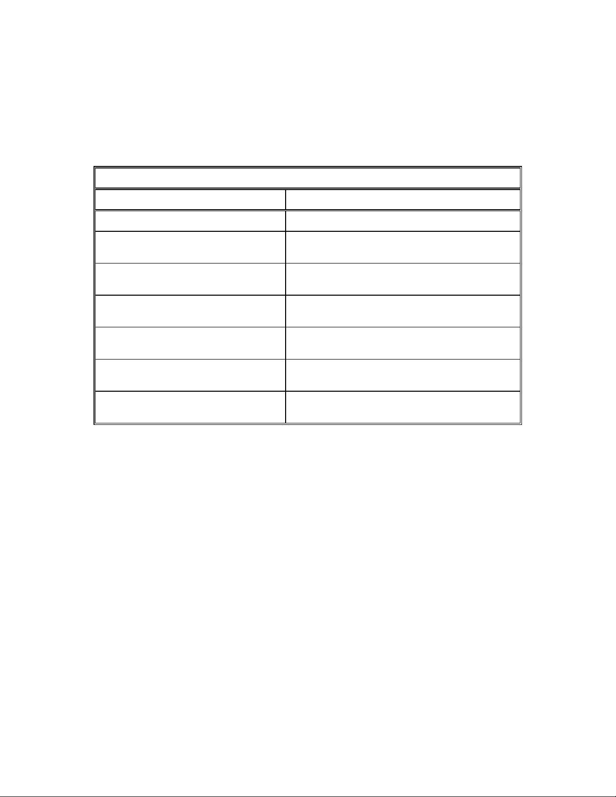
The following table shows the functions of the controls on the 7122B/7133B OU.
7122B/7133B OU CONTROLS
CONTROL FUNCTION
MAIN POWER Circuit Breaker Controls power to the elevation, azimuth, and
polarization motors, the limit switches, and the
7122B/7133B ACU.
MAINT/REMOTE Switch In the REMOTE position only the 7122B/7133B
ACU controls antenna movement. In the MAINT
position only the 7122B/7133B OU controls
antenna movement.
EMERGENCY STOP Switch Located on the side of the OU. The push button
must be pulled outward before the ACU or OU
can be used to control the movement of the
antenna. Pressing this button removes the
control voltage to the motor contactor.
EL UP/DOWN Switch Momentary contact switch that controls the
elevation movement of the antenna.
POL CW/CCW Switch Momentary contact switch that controls the
polarization movement of the feed tube.
AZ CW/CCW Switch Momentary contact switch that controls the
azimuth movement of the antenna.
3 - 2
Page 13

ATP
4.0 ACCEPTANCE TEST PROCEDURE
4.1 Preliminary Information
This test procedure is intended to serve as the final proof of performance document
for the 7122B/7133B ACU, subsequent to field installation and set-up. Prior to the
performance of these tests, the system must have been installed and adjusted as
described in Section 2.0 of this manual. Motor rotation direction should be normalized
and limit stops should be set.
4.2.1 Maintenance Mode
1. On the 7122B/7133B OU set the MAIN POWER circuit
breaker to ON. _______(Check)
2. Verify that the EMERGENCY STOP button is in the out
position. _______(Check)
3. Set the MAINT/REMOTE switch to MAINT. _______(Check)
4. Using the EL UP/DOWN switch, drive the antenna and
verify correct directional movement of the antenna. _______(Check)
5. Using the EL UP/DOWN switch, drive the antenna UP
and verify that the limit switch stops the movement of
the antenna. _______(Check)
6. Using the EL UP/DOWN switch, drive the antenna DOWN
and verify that the limit switch stops the movement of the
antenna. _______(Check)
7. Using the AZ CW/CCW switch, drive the antenna and
verify correct directional movement of the antenna. _______(Check)
8. Using the AZ CW/CCW switch, drive the antenna CW
and verify that the limit switch stops the movement of
the antenna. _______(Check)
9. Using the AZ CW/CCW switch, drive the antenna CCW
and verify that the limit switch stops the movement of
the antenna. _______(Check)
4-1
Page 14

10. Using the POL CW/CCW switch, drive the feed horn and
verify correct directional movement of the feed horn. _______(Check)
11. Using the POL CW/CCW switch, drive the feed horn CW
and verify that the limit switch stops the movement of the
feed horn. _______(Check)
12. Using the POL CW/CCW switch, drive the feed horn CCW
and verify that the limit switch stops the movement of the
feed horn. _______(Check)
4.2.2 Remote Mode
1. Set the MAINT/REMOTE switch on the 7122B/7133B OU
to REMOTE. _______(Check)
ATP
2. From the 7122B/7133B ACU drive the antenna in elevation
and verify correct directional movement of the antenna. _______(Check)
3. Drive the antenna UP and verify that the limit switch
stops the movement of the antenna. _______(Check)
4. Drive the antenna DOWN and verify that the limit switch
stops the movement of the antenna. _______(Check)
5. From the 7122B/7133B ACU drive the antenna in
azimuth and verify correct directional movement of
the antenna. _______(Check)
6. Drive the antenna CW and verify that the limit switch
stops the movement of the antenna. _______(Check)
7. Drive the antenna CCW and verify that the limit switch
stops the movement of the antenna. _______(Check)
8. From the 7122B/7133B ACU drive the feed horn and verify
correct directional movement of the feed horn. _______(Check)
9. Drive the feed horn CW and verify that the limit switch
stops the movement of the feed horn. _______(Check)
10. Drive the feed horn CCW and verify that the limit switch
stops the movement of the feed horn. _______(Check)
4-2
Page 15

ATP
4-3
Page 16

5.0 RECOMMENDED SPARES
The following tables list the recommended spares for the 7122B/7133B ACU
and Drive Cabinet.
7122B/7133B ACU RECOMMENDED SPARES
QTY DESCRIPTION VERTEX PART NO.
1 Circuit Breaker, 1A CCB007
SPARES
1
1 PCB, Display BBB035
1 PCB, Resolver/Digital BBB056
1 PCB, Binary/BCD BBB057
1 PCB, Switch BBB042
QTY DESCRIPTION VERTEX PART NO.
1 Circuit Breaker, 3-Pole, 20A CCB074
1 Circuit Breaker, 3-Pole, 6A CCB092
1 Circuit Breaker, 3-Pole, 2A CCB081
1 Circuit Breaker, 1-Pole, 1A CCB076
1 Reversing Contactor CPC056
Power Supply +5, -12 VDC
7122B/7133B DRIVE UNIT RECOMMENDED SPARES
CPS004
1 Relay, Thermal Overload 4.0A BRL125
1 Relay, Thermal Overload 1.6A BRL126
1 Power Supply, 24 VDC CPS002
1 PCB, Relay 800057-01
1 PCB, Switch 800057-02
5-1
Page 17

ENGINEERING DRAWINGS
6.0 ENGINEERING DRAWINGS
The following list shows the engineering drawings provided in this section.
200000 Binary-BCD Board Schematic
201023 Drive Unit (3 PH POL) 208-240 VAC 3 Phase, 7133B Custom
201027 Antenna Drive Unit 208-220-240 VAC 3 Phase, 7133B Series 2
800020 7122B Outside Unit Top Assembly and Wiring Diagram
800026 7122/7133 A, B, and C Antenna Control Unit Front PC Board Layout
800029 7122/7133 Controller Resolver to Digital PC Board Assembly
800032 Model 7133A/7133B Front Switch PC Board Layouts and Assemblies
800034 Model 7122/7133 Antenna Controller Binary to BCD PC Board Assembly
800050 Model 7122A/7122B Front Switch PC Board Layouts and Assemblies
800057 Model 7133B OU Drive Unit Relay and Switch PC Board Assemblies
800151 Model 7122B Drive OU Relay and Switch PC Board Assemblies
800153 Model 7122B Antenna Control Unit Assembly and Wiring Diagram
800455 Model 7133B Antenna Control Unit 120/220-240 VAC, 1PH STD
800631 Antenna Drive Unit 380-415 VAC, 3 Phase Model 7133B
6-1
Page 18

ACRONYMS/ABBREVIATIONS
APPENDIX A - ACRONYMS AND ABBREVIATIONS
The following is a list of acronyms and abbreviations that are used by Vertex
Control Systems and may appear in this manual.
A Amperes
AC Alternating Current
ACS Antenna Control System
ACU Antenna Control Unit
A/D Analog-to-Digital
ADU Antenna Drive Unit
AGC Automatic Gain Control
AOS Acquisition of Star
ASCII American Standard Code for Information Interchange
ASSY Assembly
AST Adaptive Steptrack
AZ Azimuth
BCD Binary Coded Decimal
BDC Block Downconverter
BIT Built-In Test
BW Bandwidth
CCW Counterclockwise
CFE Customer-Furnished Equipment
COM Common
CPU Central Processing Unit
CR Carriage return
CRLF Carriage return/line feed
CW Clockwise
dB Decibel
dBm Decibel referred to 1 milliwatt
DC Direct Current
deg Degrees
DMM Digital Multimeter
DOS Disk Operating System
EIA Electronic Industries Association
EIC Encoder Input Circuit
EL Elevation
EPROM Erasable Programmable Read-Only Memory
E STOP Emergency stop
A - 1
Page 19

ACRONYMS/ABBREVIATIONS
FLT Fault
FSM Finite State Machine
FWD Forward
GHz Gigahertz
GND ground
HB High Byte
HP horsepower
Hz Hertz
I/O Input/Output
IC Integrated Circuit
IEC International Electrotechnical Commission
IEE Institute of Electrical Engineers
IEEE Institute of Electrical and Electronic Engineers
IF Intermediate Frequency
ISIO Intelligent Serial Input/Output
km Kilometer
LB Low Byte
LED Light-Emitting Diode
LNA Low Noise Amplifier
LOS Loss of Signal (Loss of Star)
LSB Least Significant Bit
LSI Large Scale Integration
LT Long-term
M Meter
M&C Monitor and Control
mA Milliamperes
mb Multibody (propagator)
MHz Megahertz
ms Millisecond
N/A Not applicable
NEC National Electrical Code
NEMA National Electrical Manufactures Association
NORAD North American Air Defense Command
NVRAM Nonvolatile Read-Only Memory
O&M Operations and Maintenance
OPT Orbit Prediction Tracking
A - 2
Page 20

PC Printed circuit
PCB Printed-Circuit Board
PH Phase
PLL Phase-Lock Loss
PMCU Portable Maintenance Control Unit
POL Polarization
p-p Peak-to-peak
PROG Program
PROM Programmable Read-Only Memory
RAM Random Access Memory
RC Resistance-capacitance
RDC Resolver-to-Digital Converter
REV Reverse
RF Radio Frequency
RFI Radio Frequency Interference
RMS Root mean square
ROM Read-Only Memory
rpm Revolutions per minute
ACRONYMS/ABBREVIATIONS
sec Second
SPST Single-Pole Single-Throw
ST Short-term
STD Standard
2b Two-body (propagator)
TBT Tracking Band Translator
TBU Test Bed Unit
TEE True Equinox and Equator
TT&C Telemetry, Tracking, and Control
UTC Coordinated Universal Time
VVolts
A - 3
Page 21

TECHNICAL SUPPORT
APPENDIX B - TECHNICAL SUPPORT
If you have any questions or problems that are not addressed by the manual, there
are several ways to contact our technical support team.
1. Phone us at (903) 295-1480.
2. Email us at support@vcsd.com.
3. Make copies of the following Technical Inquiry form and fax us your questions
at (903) 295-1479.
4. Contact us on our web site at www.vcsd.com.
B-1
Page 22

Technical Inquiry FAX (903) 295-1479
CUSTOMER NAME: SITE:
CONTACT: PHONE: EXT:
FAX: EMAIL:
Tech Support
EQUIPMENT: (INCLUDE MODEL, NAME, AND SERIAL NUMBER OF ALL PERTINENT EQUIPMENT)
1. Model:
2. Model:
3. Model:
4. Model:
OTHER EQUIPMENT
TECHNICAL QUESTION/PROBLEM:
S/N:
_________________
_________________
_________________
_________________
VCSD RESPONSE:
VCSD TROUBLESHOOTER DATE TIME REF. NO.
B-2
 Loading...