

Page 1
TM
POWER MONITORING
INSTALLATION GUIDE
H6810, H6811,
H6812
DANGER
HAZARD OF ELECTRIC SHOCK, EXPLOSION, OR ARC FLASH
• Follow safe electrical work practices. See NFPA 70E in the USA, or applicable local codes.
• This equipment must only be installed and serviced by qualified electrical personnel.
• Read, understand and follow the instructions before installing this product.
• Turn off all power supplying equipment before working on or inside the equipment.
• Use a properly rated voltage sensing device to confirm power is off.
DO NOT DEPEND ON THIS PRODUCT FOR VOLTAGE INDICATION
• SECONDARY LEADS/TERMINALS OF CURRENT OUTPUT (e.g. 5A) CTs MUST BE SHORTED,
OR CONNECTED TO THE BURDEN AT ALL TIMES.
Failure to follow these instructions will result in death or serious injury.
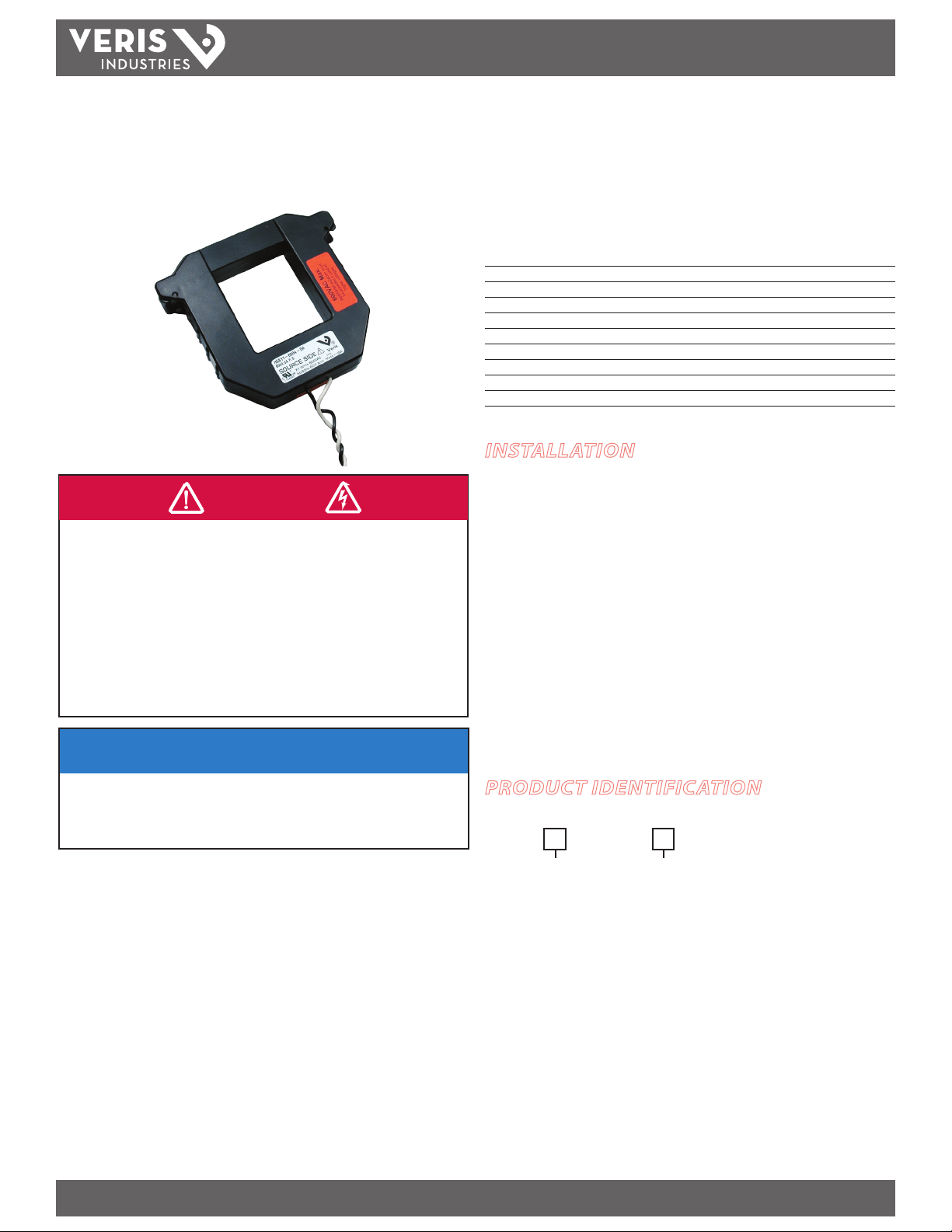
H681x-5A SERIES
5 Amp Split-Core Current Transformers
Installer’s Specifications
Output at Rated Current 5 Amps AC
Accuracy see table (page 2)
Leads 18 AWG, UL 1015 twisted pair, 6’ (1.8 m) standard leng th
Operating Temperature Range -15° to 60°C (5° to 140°F)
Storage Temperature Range -40° to 70°C (-4 0° to 158°)
Humidity Range 0-95% noncondensing
Max. Voltage L-N Sensed Conductor 600 VAC (basic insulation rating)
Frequency Range 50/60 Hz
Altitude of Operation 3km max.
Installation Categor y Cat II or Cat III
INSTALLATION
1. Disconnect and lock out power to the primary circuit before installing these
current transducers (CTs).
2. Connect the secondary leads to the burden or test switching/shorting bar. The
white wire is the X1 lead.
3. Depress the tabs on one end of the current transformer to open it and slip it over
the primary leads. Note labeling on product indicating “source side.”
4. Check the core ends on both sections of the CT to assure there is no rust or debris in
the closure areas.
5. Close and latch the CT, and mount it securely.
6. Reconnect power to the panel.
NOTICE
• This product is not intended for life or safety applications.
• Do not install this product in hazardous or classified locations.
• The installer is responsible for conformance to all applicable codes.
• Mount this product inside a suitable fire and electrical enclosure.
Optional mounting kit available for the H6810, H6811, and H6812. See Veris AH06.
PRODUCT IDENTIFICATION
Model/Amps
H681
Small:
0-200 = 200A
0-300 = 300A
Medium:
1-400 = 4 00A
1-600 = 60 0A
1-800 = 800A
Large:
2-800 = 80 0A
2-1000 = 1000A
2-1200 = 1200A
2-1600 = 1600A
2-2000 = 2000A
2-2400 = 2400A
Output Type
-
5A
= 5 Amp
Z201970-0G PAGE 1 ©2012 Veris Industries USA 800.354.8556 or +1.503.598.4564 / support@veris.com 05121
Alta Labs, Enercep t, Enspector, Hawkeye, Trustat, Veris, and the Veris ‘ V’ logo are trademark s or registered tradema rks of Veris Industries, L.L .C. in the USA and /or other count ries.
Page 2
H681x-5A SERIES
Wire ti
TM
INSTALLATION GUIDE
OPERATION
The H681x-xxx series of 5 Amp split-core current transformers provide secondary
amperage proportional to the primary (sensed) current. For use with power meters,
data loggers, chart recorders, and other instruments, the H681x Series 5 Amp CTs
provide a cost-eective means to transform electrical service amperages to a 0 to 5
Amp level compatible with monitoring equipment.
DIMENSIONS
F
B
C
D
A
B
C
A
B
C
A
E
F
D
E
F
D
E
H6810
SMALL (SIZE 2)
200/300 Amp
A = 3.8" (96 mm)
B = 1.2" (30 mm)
C = 1.3" (31 mm)
D = 1.2" (30 mm)
E = 4.0" (100 mm)
F = 4.8" (121 mm)
H6811
MEDIUM (SIZE 3)
400/600/800 Amp
A = 4.9" (125 mm)
B = 2.9" (73 mm)
C = 2.5" (62 mm)
D = 1.2" (30 mm)
E = 5.2" (132 mm)
F = 6.0" (151 mm)
H6812
LARGE (SIZE 4)
800/1600/2400 Amp
A = 4.9" (125 mm)
B = 5.5" (139 mm)
C = 2.5" (62 mm)
D = 1.2" (30 mm)
E = 7.9" (201 mm)
F = 6.0" (151 mm)
ACCURACY
Model # Accuracy from 10%
to 100% of CT Rating
H6 810-200 A-5A 1% 2.5
H6810-300A-5A 1% 2.5
H6 811-400A -5A 1% 5.0
H6 811- 600A-5 A 1% 5.0
H6 811-80 0A- 5A 1% 12.5
H6812- 800A-5A 1% 5.0
H6812-1200A-5A 1% 22.5
H6 812-1600A -5A 1% 22.5
H6 812-240 0-5A 1% 22.5
Burden Capacity (VA)
NOTES
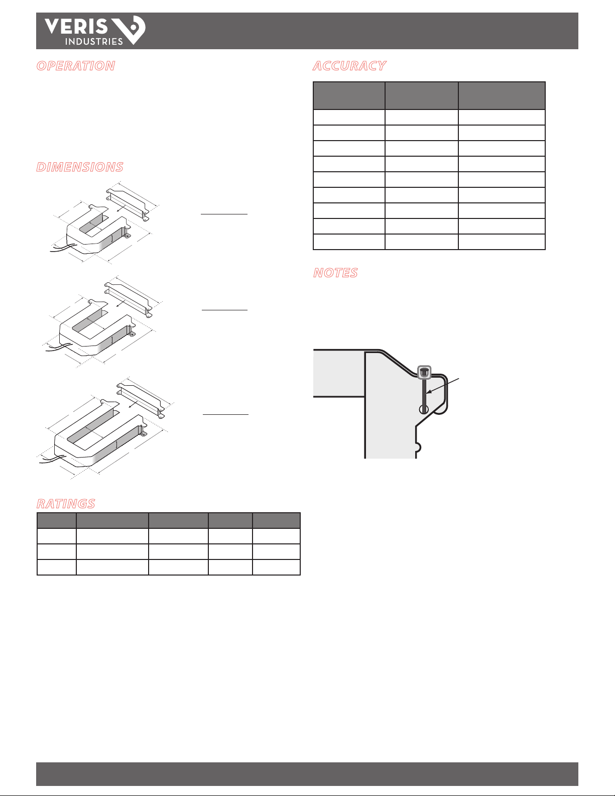
Accuracy is specied with the primar y conductor(s) centered in the CT window.
In any application where fault currents can exceed 20 times rated current of CT, use
wire ties or similar fasteners to secure the I-bar to the CT housing (see below). Secure
both sides of the I-bar.
Secure I-bar with a wire tie
in applications where a fault
current could exceed 20x
rated curre nt.
Max. voltage without additional insulation: 600VAC for the H6810, H6811, and H6812
Do not apply current transformers to circuits having a phase-to-neutral voltage
RATINGS
Model Sensing Current (A) Frequency (Hz) Output (A) Weight (kg)
H6810 0 to 300 50/60 0 to 5 0.340
greater than the stated maximum voltage unless adequate additional insulation is
applied between the primary conductor and the current transformers. Veris assumes
no responsibility for damage of equipment or personal injury caused by transformers
operated on circuits above their published ratings.
H6 811 0 to 800 50/60 0 to 5 0.580
H6812 0 to 2400 50/60 0 to 5 0.870
These products provide basic insulation to 600 VAC between the sensed conductor
and the output leads. For reinforced applications, the sensed conductor must
be provided with appropriate insulation. Reinforced insulation is provided for
applications to 300 VAC between the sensed conductor and the output leads.
Z201970-0G PAGE 2 ©2012 Veris Industries USA 800.354.8556 or +1.503.598.4564 / support@veris.com 05121
Alta Labs, Enercep t, Enspector, Hawkeye, Trustat, Veris, and the Veris ‘ V’ logo are trademark s or registered tradema rks of Veris Industries, L.L .C. in the USA and /or other count ries.
 Loading...