

Page 1
TM
HAZARD OF ELECTRIC SHOCK, EXPLOSION, OR ARC FLASH
• Follow safe electrical work practices.
See NFPA 70E in the USA, or applicable local codes.
• This equipment must only be installed and serviced by qualified electrical personnel.
• Read, understand and follow the instructions before installing this product.
• Turn off all power supplying equipment before working on or inside the equipment.
• Use a properly rated voltage sensing device to confirm power is off.
DO NOT DEPEND ON THIS PRODUCT FOR VOLTAGE INDICATION
• Only install this product on insulated conductors.
Failure to follow these instructions will result in death or serious injury.
DANGER
CURRENT MONITORING
INSTALLATION GUIDE
H535 535
TM
Enclosed Relay
Installer’s Specifications
Sensor Power Induced from the monitored conductor
Amperage Range 0.25 to 15 A
Frequency Range 50-60 Hz
Operating Temperature Range -15° to 50°C (5° to 122°F)
Operating Humidity Range 0-95%, noncondensing
Wire to Relay Contact s Use 12 AWG (3.3 mm2) wire or larger*
Relay Switching C apacity at 120 VAC 1 HP
Relay Outpu t SPST F.S. N.O. or N.C., 15 Amps
Relay Coil 24 VAC/DC; 36 mA nom.
Terminal Block Torque Relay control ter minals: 3.5 in-lb (0.4 N-m)
All other terminals: 12 in-lb (1.35 N-m)
Agency Approvals UL508, Installation Category III
* For current loads up to 10A, use 75°C rated wire insulation. For loads greater than 10A, use 90°C
rated wire insulation.
The product design provi des for basic insulation only.
Quick install
1. Disconnect power sources prior to installation.
NOTICE
• This product is not intended for life or safety applications.
• Do not install this product in hazardous or classified locations.
• The installer is responsible for conformance to all applicable codes.
• Mount this product inside a suitable fire and electrical enclosure.
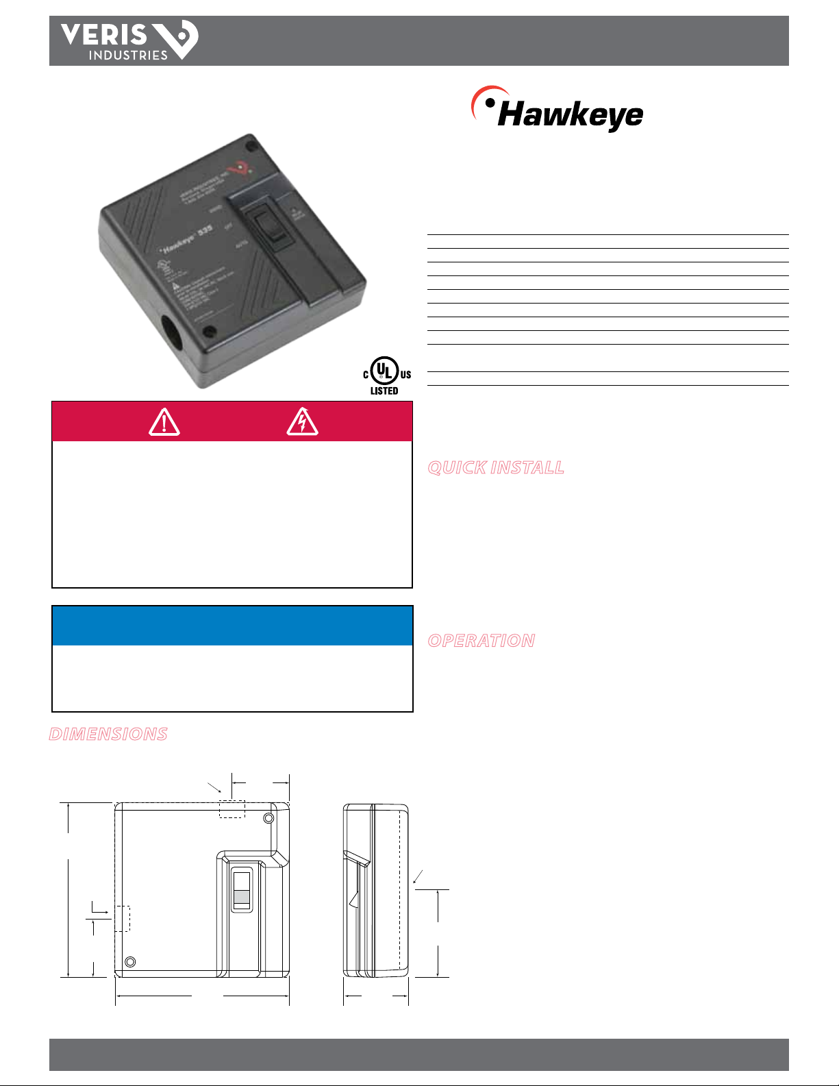
Dimensions
C
Wire
Opening
4.25"
(108 mm)
Wire
Opening
C
L
1.16"
(30 mm)
Z202808-0E PAGE 1 ©2012 Veris Industries USA 800.354.8556 or +1.503.598.4564 / support@veris.com 07121
Alta Labs, Enercep t, Enspector, Hawkeye, Trustat, Veris, and the Veris ‘ V’ logo are trademark s or registered tradema rks of Veris Industries, L.L .C. in the USA and /or other countri es.
L
1.16"
(30 mm)
4.25"
(108 mm)
1.53"
(39 mm)
2. Remove the sensor lid and wire the command relay connections and relay controls
to the base.
3. Set the relay contact jumper.
4. This device has four wiring options, detailed on page 2-3 of this installation guide.
Choose the option appropriate to the application and follow instructions.
operation
The H535 combines a switching relay and a Hand-O-Auto (HOA) switch in a single
housing. The H535 is connected in series between the power source and the motor
device. It operates at amperages up to a maximum of 15 A, and the relay and HOA
switch control the on/o functioning of the motor. The H535 requires no additional
power source for operation.
Wire
Opening
C
L
2.13"
(55 mm)
Page 2
TM
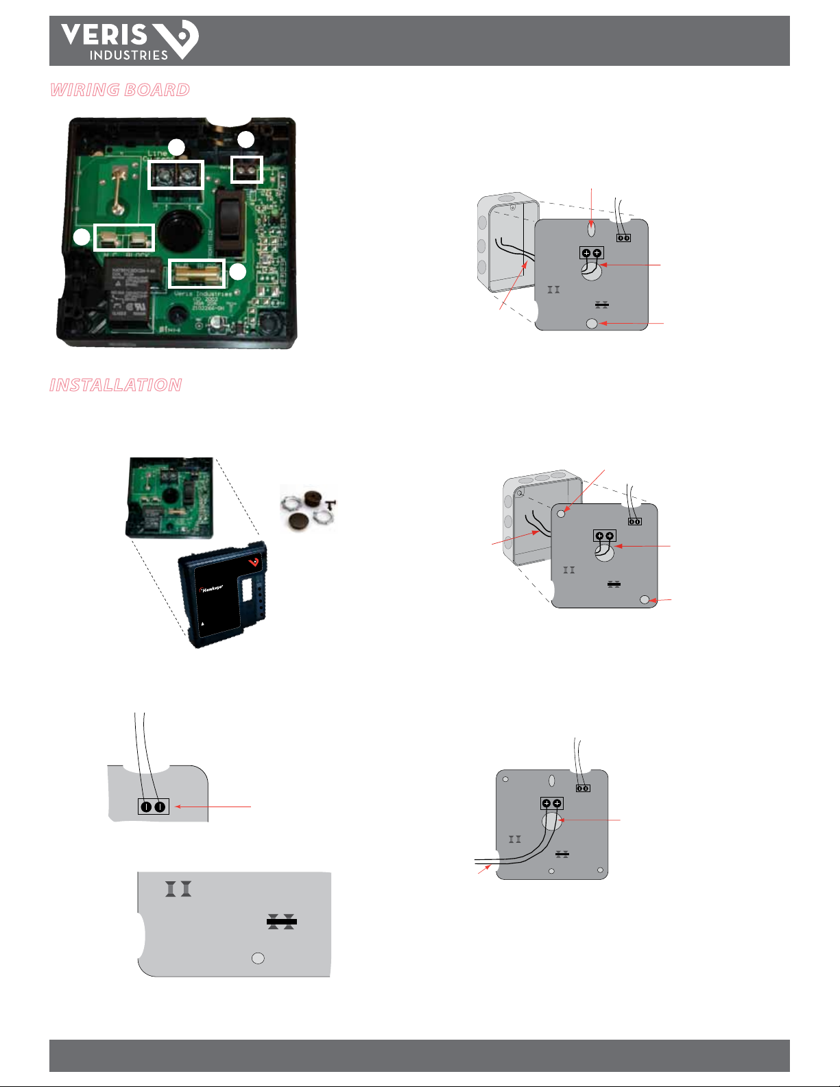
Wiring boarD
H535
1
3
2
1. Line Current Terminals
2. 24VAC/DC Relay Control
3. N.C. Block
4
4. N.O. Block
installation
Prior to installation, disconnect and lock out all power sources.
INSTALLATION GUIDE
4. Select one of the following mounting congurations (a, b, c, or d) to match your
installation.
a.) duplex box:
Mounting slot
Connect line voltage wires
N.C. Block
N.O. Block
Line Voltage
Wires
Wire the 12 AWG lines from the controller through the back of the device, to
the line current terminals. Tighten line current terminal blocks to 12 in-lb.
(1.35 N-m) torque. Use the base as a template for mounting to the wall using
the mounting hole and slot shown.
to line current terminals
Mounting hole
1. Open the device. Set aside the lid and the bag of hardware enclosed.
VERIS INDUSTRIES, INC.
P ORTL AND , OR EGON U SA
TOLL FREE USA 1.800.354.8556
TEL USA 1.503.598.4564
FAX USA 1.503.598.4664
RS
535
HAND
OC
OFF
SO
AUTO
SP
CAUTION: Consult instructions
prior to installation
!
STATUS OUTPUT: 1A@30VAC/DC
RELAY COIL: 24VAC/DC; 16mA nom.
RELAY OUTPUT: 16(8)A@250VAC; 3/4 HP
SC
2. Wire the 24 AC/DC relay control through the top hole of the device. Use only copper
conductors for command relay inputs. Tighten terminal blocks to 3.5 in-lb (0.4
N-m) torque. Keep wires away from the N. O. and N. C. jumper blocks.
24VAC/DC Relay Control
3. Set the relay contact jumper for N.O. or N. C. operation (the device is shipped with
the jumper set in the N.O. position).
b.) 4S junction box:
Mounting hole
Line Voltage
Wires
Connect line voltage wires
to line current terminals
Mounting hole
Wire the 12 AWG lines from the controller through the back of the device, to
the line current terminals. Tighten line current terminal blocks to 12 in-lb.
(1.35 N-m) torque. Use the base as a template for mounting to the wall using
the mounting holes shown.
c.) surface mounting:
Connect line voltage wires
to line current terminals
Line Voltage
Wires
N.C. Block
N.O. Block
Wire the 12 AWG lines from the controller through the side of the device, onto
the line current terminals. Tighten line current terminal blocks to 12 in-lb.
(1.35 N-m) torque. Use the base as a template for mounting to the wall using
any of the mounting holes shown.
Z202808-0E PAGE 2 ©2012 Veris Industries USA 800.354.8556 or +1.503.598.4564 / support@veris.com 07121
Alta Labs, Enercep t, Enspector, Hawkeye, Trustat, Veris, and the Veris ‘ V’ logo are trademark s or registered tradema rks of Veris Industries, L.L .C. in the USA and /or other countri es.
Page 3
TM
Connect line voltage wires
to line current terminals
H535
INSTALLATION GUIDE
d.) nipple mount to another enclosure:
Insert the conduit nuts (provided) into the slots in the side hole of the device
for additional weight support.
ENCLOSURE
Line voltage wires
Wire the 12 AWG lines from the controller through the side of the device,
from the enclosure to the line current terminals. Tighten line current terminal
blocks to 12 in-lb. (1.35 N-m) torque.
5. Use the knockout seal to cover any unused holes in the housing. Attach the cover,
securing with the screws provided.
NOTE: If a conduit is used, connect the conduit to the mounti ng hub before connecting it to the
device. Be sure to support the H535 housing when nipple-mounted to an other enclosure, or the
unit may shift on o pening, potentially causing undue stress on the wiring a nd the terminals.
Nipple to existing enclosure
(conduit nipple fitting not provided)
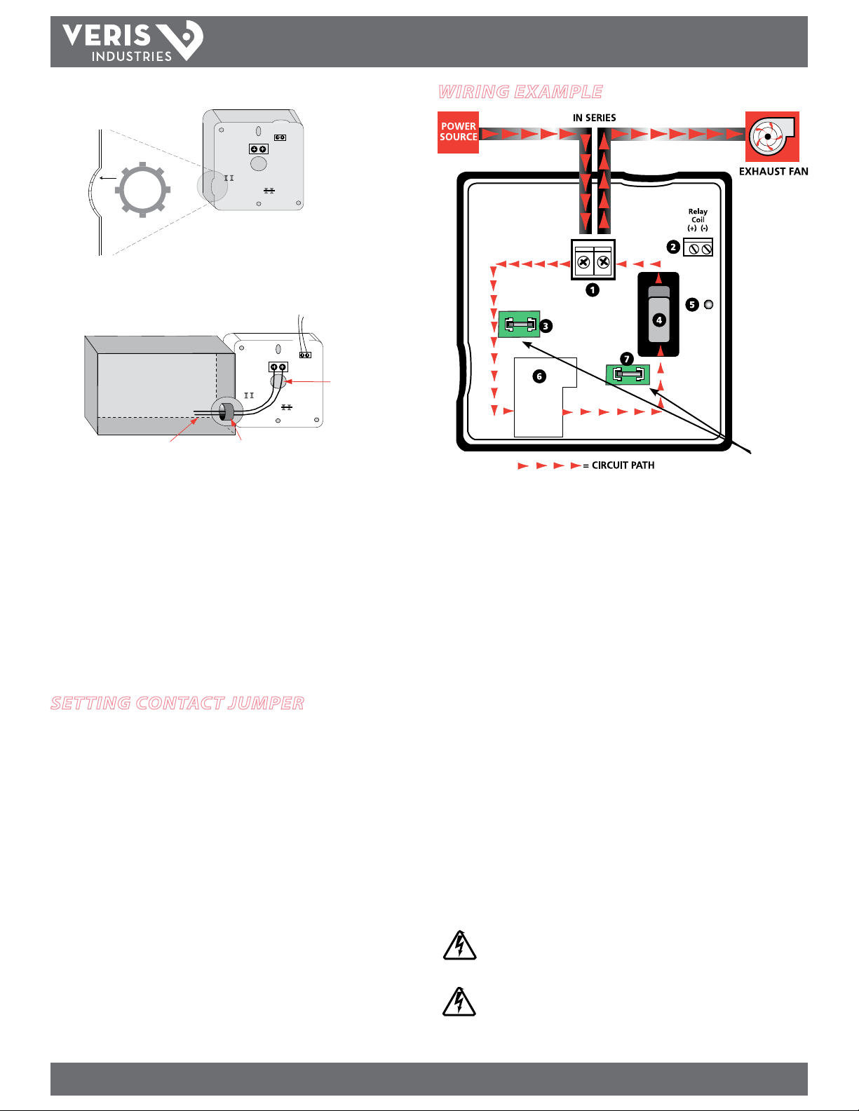
Wiring example
Keep all wires away
from the jumper blo ck
areas.
1. Relay Contacts: Wire the H535 in series with the load using these terminals.
2. Relay Coil Terminal Blocks: Wire the output signal from the control panel to
actuate the relay. 24 VAC/DC; 36mA nominal
3. N.C. Relay Jumper Block: Insert a jumper here to ensure normally closed relay
operation when the switch is in auto position. Disconnect power to the device
before before touching the jumper.
4. H.O.A . Switch: Control the motor locally.
HAND – When the switch is in this position, the motor is always on.
setting contact jumper
The H535 has a jumper for N.O. or N.C. relay function. The jumper aects the relay
contacts only when the HOA switch is in AUTO. The product is shipped with the
jumper in the N.O. position. To select N.C. function, move to the N.C. jumper block.
Always disconnect power to the device before before touching the jumper.
OFF – When the switch is in this position, the motor is always o.
AUTO – When the switch is in this position, the control system commands the
motor.
5. Relay Status LED: For positive indication of energized coil.
6. Relay: Enables actuation of a circuit by a control system.
7. N.O. Relay Jumper Block: Insert a jumper here to ensure normally open relay
operation when the switch is in auto. Disconnect power to the device before
before touching the jumper.
CAUTION!
Do not rely on status indicators to de termine whether or n ot the relay contacts are
connected to a power source. Doing so may result in i njury or death from electrical
shock.
If the connections to the unit a re made through more than one metallic conduit, bond
the conduits to prevent the hazard of elec tric shock. A bonding plate is available (Veris
Z202808-0E PAGE 3 ©2012 Veris Industries USA 800.354.8556 or +1.503.598.4564 / support@veris.com 07121
Alta Labs, Enercep t, Enspector, Hawkeye, Trustat, Veris, and the Veris ‘ V’ logo are trademark s or registered tradema rks of Veris Industries, L.L .C. in the USA and /or other countri es.
pa rt AH10 ).
 Loading...