

Page 1
TM
HAZARD OF ELECTRIC SHOCK, EXPLOSION, OR ARC FLASH
• Follow safe electrical work practices.
See NFPA 70E in the USA, or applicable local codes.
• This equipment must only be installed and serviced by qualified electrical personnel.
• Read, understand and follow the instructions before installing this product.
• Turn off all power supplying equipment before working on or inside the equipment.
• Use a properly rated voltage sensing device to confirm power is off.
DO NOT DEPEND ON THIS PRODUCT FOR VOLTAGE INDICATION
• Only install this product on insulated conductors.
Failure to follow these instructions will result in death or serious injury.
DANGER
Removable Mounting Bracket
0.3”
(8 mm)
6 AWG max.
1.6”
(40 mm)
1.5”
(38 mm)
0.6”
(15 mm)
1.8”
(46 mm)
Ø 0.18” (x2)
(5 mm)
CURRENT MONITORING
INSTALLATION GUIDE
US Patent 7,193,428
(other patents pending)
H308
RoHS
Compliant
TM
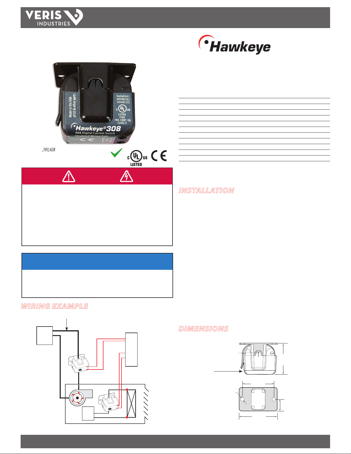
308
Micro Split-Core Current Switch,
Adjustable Trip Point
Installer’s Specifications
Amperage Range 0.75 to 50 A Continuous
Setpoint Adjustable
Sensor Supply Voltage Induced from monitored conductor
Insulation Class 600 VAC RMS (UL), 300 VAC RMS (CE), insulated conductors only
Temperature Range -15° to 60°C (5° t o 140°F)
Humidity Range 10-90% RH non-condensing
Frequency 50/60 H z
Status Output Ratings N.O. 1.0 A@30 VAC/DC, not polarity sensitive
O State Resis tance Open switch represents 1+ MΩ of resistance
Terminal Block AWG Range 16-22 AWG
Terminal Block Torque Range 7 in-lb
Agency Approvals UL508, E150462
Specication Note: For CE compliance, conductor shall be insulated according to IEC 61010‑1:2010,
Installation Category III or equivalent. The product design provides for functional insulation only.
INSTALLATION
Disconnect and lock out power to the enclosure containing the
conductor to be monitored.
NOTICE
• This product is not intended for life or safety applications.
• Do not install this product in hazardous or classified locations.
• The installer is responsible for conformance to all applicable codes.
• Mount this product inside a suitable fire and electrical enclosure.
WIRING EXAMPLE
Insulated Conductor ONLY
BUILDING AUTOMATION
POWER
SOURCE
Z204964-0C PAGE 1 ©2012 Veris Industries USA 800.354.8556 or +1.503.598.4564 / support@veris.com 02121
Alta Labs, Enercep t, Enspector, Hawkeye, Trustat, Veris, and the Veris ‘ V’ logo are trademark s or registered tradema rks of Veris Industries, L.L .C. in the USA and /or other countri es.
POWER
SOURCE
UNIT VENT HEATER
CONTROLLER
DI
DI
1. Locate a mounting surface for the removable mounting bracket that will allow
the monitored conductor to pass through the center window when it is installed
and that will keep the product at least 1/2” from any uninsulated conduc tors.
Determine cable routing for the controller connection, allowing wiring to reach
the mounting location.
2. Drill holes to mount the bracket to the chosen surface using the included screws.
3. Wire the output connections between the sensor and the controller (solid-state
contact).
4. Snap the sensor over the wire to be monitored and push the latch until it is
securely closed. Clip the assembly to the mounting bracket.
5. Calibrate the current switch (see Calibration section).
6. Secure enclosure and reconnect power.
DIMENSIONS
Setpoint
adjustment
screw here
Page 2
TM
H308
INSTALLATION GUIDE
OPERATION
The H308 is a current-sensitive switching device that monitors current (amperage) in
the conductor passing through it. A change in the conductor’s amperage that crosses
the adjustable switch threshold plus the hysteresis value causes the resistance of the
FET status output to change state, similar to the action of a mechanical switch. The
status output is suitable for connection to building controllers or other appropriate
data acquisition equipment operating at up to 30 volts. The H308 requires no external
power supply to generate its output.
NOTES
For load currents greater than sensor maximum rating:
Use a 5 Amp (H68xx series) Current Transformer (CT) as shown. This technique can be
combined with wrapping (see below) to add range for a low current load on a high
current source.
240A
> 50 A (Sensor max.)
300A:
5A
H68xx‑5A CT
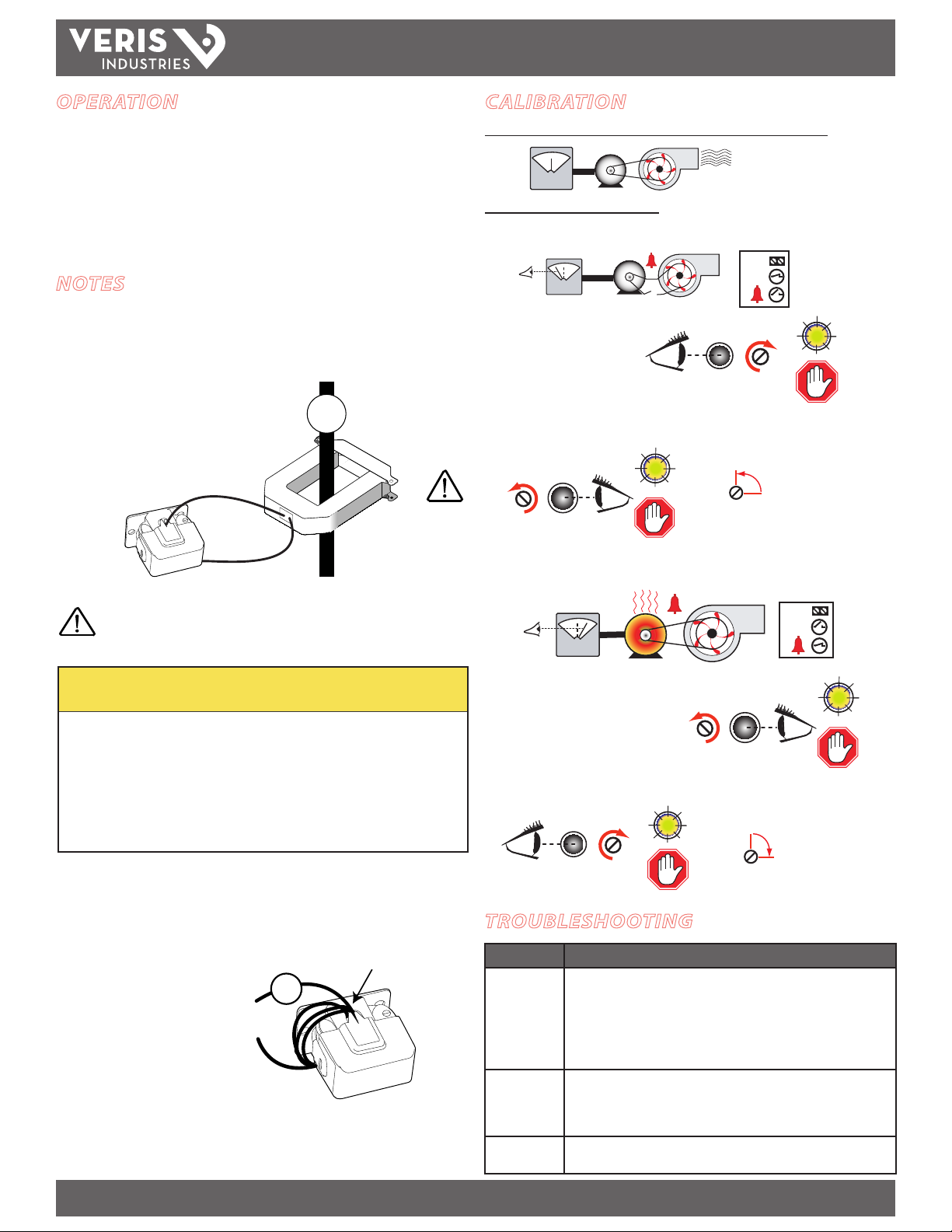
CALIBRATION
Before beginning calibration, establish normal load conditions.
OK!
A
Then choose either A or B below.
A. To monitor under-current (belt loss, coupling shear, status)
!
OK!
A
1. Turn setpoint screw
clockwise until Status OPEN
LED turns ON.
2. Slowly turn the screw counter-clockwise until the Status CLOSED LED just
turns ON.
Status
Setpoint
Closed
OK!
STOP
+
Status
Open
Setpoint
1/4
STATUS
OK!
Setpoint
STOP
3.Turn the screw an
additional 1/4 turn
counter-clockwise for
operational margin.
DANGER: 5A CTs can present hazardous voltages.
Install CTs in accordance with manufacturer's instructions.
Terminate the CT secondary before applying current.
CAUTION
RISK OF EQUIPMENT DAMAGE
• Derate the product’s maximum current for the number of turns
through the sensing window using the following formula.
Rated Max. Amps ÷ Number of Turns = Max. monitored Amps
e.g. : 100A ÷ 4 Turns = 25 Amps max. in monitored conductor
• Failure to follow these instructions can result in overheating
and permanent equipment damage.
For load currents less than sensor minimum rating:
Wrap the monitored conductor through the center window and around the sensor
body to produce multiple turns. This increases the current measured by the
transducer.
< 0.75 A (Sensor Min.)
0.1A
4x
B. To monitor over-current (mechanical problems, seized impeller)
1/4
STATUS
OK!
STOP
3. Turn the setpoint
screw an additional
1/4 turn clockwise for
operational margin.
!
OK!
A
1.Turn setpoint screw
counter-clockwise until Status
Setpoint
Status
Closed
CLOSED LED turns ON.
2. Slowly turn the setpoint screw clockwise until the Status OPEN LED just turns ON.
Status
Setpoint
Open
Setpoint
+
STOP
TROUBLESHOOTING
Problem Solution
No Reading at
Controller
Setpoint screw
has no stops
Both LEDs
are lit
• Check for control voltage at sensor (<30V)
• Check for amperage in monitored conductor (> 0.75A)
• Assure that sensor core mating surfaces are clean and that the core clamp
is completely closed
• Verify that the setpoint is not above operating amps by turning screw
CCW (up to 20 turns) until the contacts close (Status Closed LED turns on).
The 20 turn setpoint screw has a slip clutch to prevent damage at either
end. To re-start the calibration process, turn the screw 20 full turns CCW.
This sets the device in its original and most sensitive position. Resume
calibration from the beginning.
The screw has been turned too far CW. Turn the screw 20 full turns CCW
and resume calibration from the beginning.
Z204964-0C PAGE 2 ©2012 Veris Industries USA 800.354.8556 or +1.503.598.4564 / support@veris.com 02121
Alta Labs, Enercep t, Enspector, Hawkeye, Trustat, Veris, and the Veris ‘ V’ logo are trademark s or registered tradema rks of Veris Industries, L.L .C. in the USA and /or other countri es.
 Loading...