

Page 1
TM
HAZARD OF ELECTRIC SHOCK, EXPLOSION, OR ARC FLASH
• Follow safe electrical work practices.
See NFPA 70E in the USA, or applicable local codes.
• This equipment must only be installed and serviced by qualified electrical personnel.
• Read, understand and follow the instructions before installing this product.
• Turn off all power supplying equipment before working on or inside the equipment.
• Use a properly rated voltage sensing device to confirm power is off.
DO NOT DEPEND ON THIS PRODUCT FOR VOLTAGE INDICATION
• Only install this product on insulated conductors.
Failure to follow these instructions will result in death or serious injury.
A qualied person is one who has skills and knowledge related to the construction and
operation of this electrical equipment and the installation, and has received safety
training to recognize and avoid the hazards involved. NEC2009 Article 100
No responsibility is assumed by Veris Industries for any consequences arising out of the
use of this material.
DANGER
CURRENT MONITORING
INSTALLATION GUIDE
TM
H11 D
Split-Core Current Switch,
Auto Calibration With Display
RoHS
Compliant
SPECIFICATIONS
Sensor Power Induced from monitored c urrent
Amperage Range 60 Hz: 2.5 - 200A max.
50 Hz: 3.0 - 200A max.
Status Output N.O. when device is unpowered, 1.0A@30VAC/DC
not polarity sensitive
Response Time 1 sec.
Accuracy ±2% of full scale
Frequency Range 50/60 Hz
Temperature Range -15° to 60°C (5° t o 140°F)
Humidity Range 10-90% RH non-condensing
LCD Backlight O at low currents; illuminates when monito red current exceeds 4.5A;
ashes during an alarm s tate while current remains above 4.5A
On-State Resistance ≤1.0 Ω
O-S tate Resistance ≥1.0 MΩ
Setpoint Target Range, Switch Setting A* ±40% of learned nominal cur rent;
max. learned current of 142A to enable an upper tr ip limit at or below 200A
Setpoint Target Range, Switch Setting B* ±60% of learned nominal c urrent;
max. learned current of 125A to enable an upper trip limit at or below 20 0A
Switch Setting C* On/Off Status; contac ts are closed while amperage is above 2.5A
Alarm Reset Range ±5% of learned nominal current **
Setpoint Calibration Learn Period 30 sec.; self-learning, pushb utton reset
Normal-to-Alarm Output Delay 1 sec. maximum
Alarm-to-Normal Out put Delay 30 sec. nominal
Insulation Class 600VAC RMS (UL), 300VAC RMS (CE)
Terminal Block Wire Size 24 to 14 AWG (0.2 to 2.1 mm2)
Terminal Block Torque 3.5 to 4.4 in-lbs (0.4 to 0.5 N-m)
Agency Approvals CE EN 61010-1:2001, UL508, Installation Category III, pollution degree 2
NOTICE
• This product is not intended for life or safety applications.
• Do not install this product in hazardous or classified locations.
• The installer is responsible for conformance to all applicable codes.
• Mount this product inside a suitable fire and electrical enclosure.
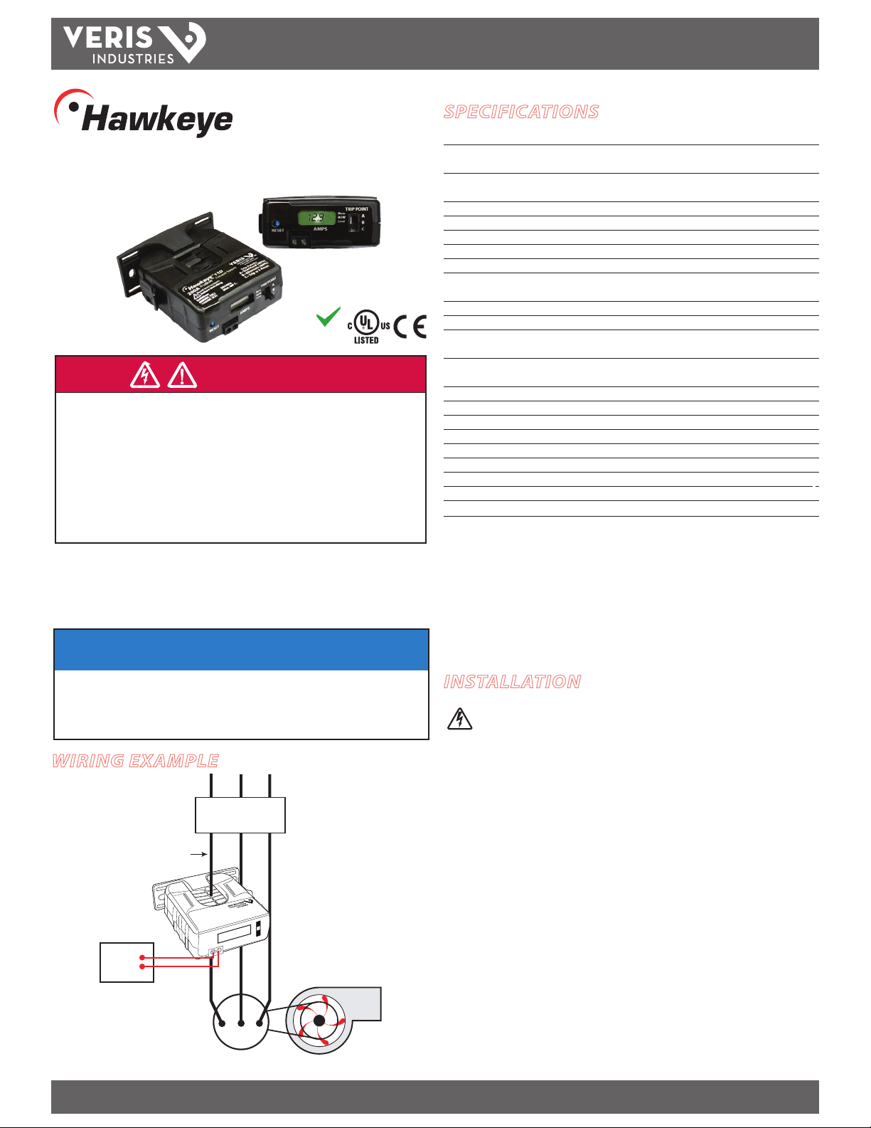
WIRING EXAMPLE
CONTACTOR
Insulated Conductor
CONTROLLER
Digital
Input
Z206073-0C PAGE 1 ©2013 Veris Industries USA 800.354.8556 or +1.503.598.4564 / support@veris.com 01131
Alta Labs, Ene rcept, Enspector, Hawk eye, Trustat,Aerosp ond, Veris, and the Veris ‘ V’ logo are trad emarks or regis tered trademar ks of Veris Industrie s, L.L.C. in the USA an d/or other countries .
MOTOR
Fan or Pump
* Trip point switch positions A and B are not for use in ap plications where the current will uctuate
by more than 40% (A) or 60% (B) of the nominal current. If the current will u ctuate by more
than 60%, use the H11D for on/o status (position C) only.
** The upper trip limit a larm resets when the current drops by 5% of the learned nominal current.
The lower trip limit alarm rese ts when the current rises by 5% of learned nominal current.
Specication Note: For CE compliance, conductor sha ll be insulated according to IEC 61010‑1:2001.
Listed for use with 75°C insulated conductors.
The product design provi des for basic insulation only.
Do not use the LCD as evidence of applied voltage.
INSTALLATION
Disconnect power to the enclosure containing the
conductor to be monitored.
1. Determine normal operating conditions for the application, and move the slide
switch to the best setpoint range (A, B, or C) for these conditions (e.g., if normal
operation, including duct opening/closing and lter blockage is 50% of the
learned nominal current, then set the slide switch to the B range (±60%), or use
the C range (on/o status) to indicate when current falls below 2.5A at 60 Hz). For
most blower systems, the 40% (A) setting is appropriate.
2. Locate a mounting surface for the removable mounting bracket that allows the
monitored conductor to pass through the center window when it is installed and
that keeps the product at least ½” from any uninsulated conductors. Determine
cable routing for the controller connection, allowing wiring to reach the mounting
location.
3. Drill holes and mount the bracket to the chosen surface using the included screws.
4. Wire the output connections between the sensor and the controller (solid-state
contact).
5. Verify that the core mating surfaces are clean. Snap the sensor over the conductor
and clip the assembly to the mounting bracket.
6. Secure the enclosure and reconnect power.
Page 2
TM
H11D
INSTALLATION GUIDE
PRODUCT OVERVIEW
The H11D is an over-current and under-current monitor intended for use with HVAC
systems (fans, blowers). When the H11D is unpowered, the status output contacts
are open. When the device is powered, the contacts close and remain closed during
normal operation. The H11D learns the nominal amperage in the conductor, then
monitors for amperage changes outside the range chosen using the slide switch. If
the amperage goes out of the established range, the contacts open, raising an alarm
in the system controller. This alarm state persists until the amperage comes back to
within range (5% of learned nominal rate below the upper trip limit or 5% of learned
nominal rate above the lower trip limit of the learned nominal conditions) and
remains within range for 30 seconds to ensure that the system has truly returned to
normal operation. If load conditions change, use the reset button to send the H11D
back into learning mode.
The status output is suitable for connection to system controllers or other data
acquisition equipment operating at up to 1 A@30 VAC/DC. The H11D requires no
external power supply to generate its output.
DIMENSIONS
Removable Mounting Bracket
3.1”
(79 mm)
Ø 0.3”
(8 mm)
1.1”
(26 mm)
1.0”
(25 mm)
0.8”
(21 mm)
2.8”
(70 mm)
2.5”
(64 mm)
3.0”
(76 mm)
Bracket can
be mounted
on three sides
for added
installation
exibility.
Self-gripping Iris
1.4”*
(36 mm)
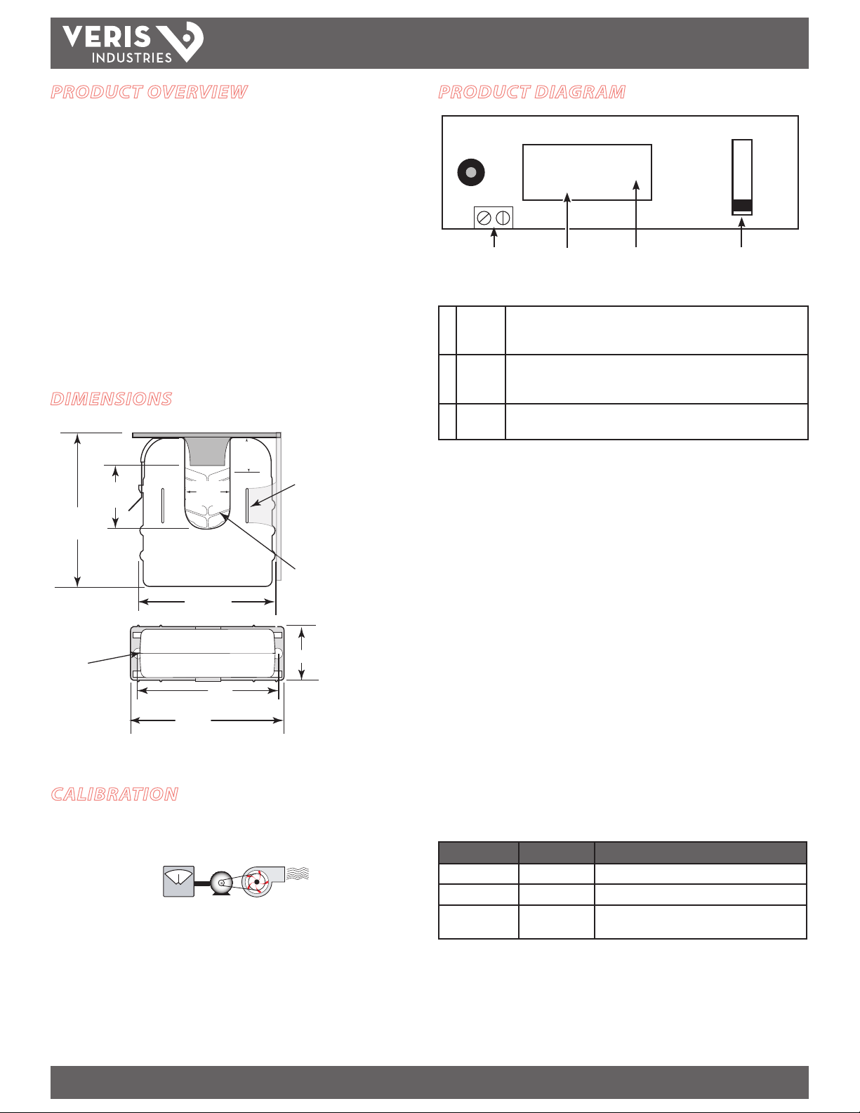
PRODUCT DIAGRAM
TRIP POINT
Mem
NOW
RESET
N.O. Status Output Slide SwitchLCD Value Indicato r
AMPS
Lrnd
Slide Switch Options
A Standard ±40% of learned nominal amperage.
Max. learned nominal current is 142 A to enable an upper trip limit at or
below 200 A.
B Alternate ±60% of learned nominal amperage.
Max. learned nominal current is 125 A to enable an upper trip limit at or
below 200 A.
C On/O
Status
Trip limits above the 200 A maximum are not permitted.
Contacts remain closed while amerage is above 2.5 A at 60 Hz.
Contacts open when amperage drops below 2.5 A.
LCD Values
If the slide switch is in position A or B, the number shown in the LCD during normal
operation cycles among the values listed below. An indicator appears to the right of
the number, indicating which value is currently visible (Mem, NOW, or Lrnd)
Mem: the trip memory, or the amperage value above or below range that
tripped the switch into alarm mode. This value remains stored in nonvolatile
memory until the H11D is reset.*
NOW: the present amperage owing through the conductor
Lrnd: the nominal amperage conditions established when the H11D is
initially powered or reset.
* The LCD only shows the trip memory value (Mem) after a trip event has
occurred. If no trip event has occurred, the LCD only cycles between NOW and
Lrnd.
A
B
C
If the slide switch is in position C (on/o status only), the LCD does not cycle. The
value displayed is always the present amperage owing through the conductor, and
CALIBRATION
The H11D automatically calibrates when first powered and each time it is
reset. Before beginning calibration, establish normal load conditions.
OK!
A
1. When amperage ows through the conductor, the H11D automatically enters the
learning mode for approximately 30 seconds.
2. When in normal operation (after learning mode is complete), the LCD cycles
between the values for the present amperage in the conductor (designated by the
indicator adjacent to NOW) and the learned nominal amperage (designated by the
indicator adacent to Lrnd).
3. If the nominal load on the conductor changes, the H11D can re-learn the new
conditions. Press the reset button to return to the learning mode.
OK!
the indicator remains on NOW.
Operation Modes
Mode Output Status LCD
Learn (30 sec) Closed (≤ 1 Ω) NOW indicator ashes on/o
Normal Operation Closed (≤ 1 Ω) Display cycles between NOW and Lrnd
Alarm Open (≥ 1 MΩ) Display cycles among all three values: NOW, Lrnd,
and Mem *
*The LCD backlight remains o at low currents. It turns on wh en the current exceeds 4.5 A and
ashes during the alarm state while t he current remains above 4.5 A.
Note: In rare instances, status contacts may close momentarily whe n the unit initially recovers
from an extend ed power o state (typically longer than 10 seconds) to an alarm state.
Z206073-0C PAGE 2 ©2013 Veris Industries USA 800.354.8556 or +1.503.598.4564 / support@veris.com 01131
Alta Labs, Ene rcept, Enspector, Hawk eye, Trustat,Aerosp ond, Veris, and the Veris ‘ V’ logo are trad emarks or regis tered trademar ks of Veris Industrie s, L.L.C. in the USA an d/or other countries .
Page 3

TM
H11D
INSTALLATION GUIDE
FUNCTIONAL ILLUSTRATION
ALARM RESET
5% Typical
NOMINAL
LEARNED
CURRENT
NORMAL
ØAAC ØAAC
POWER
ON
LEARN
(MODE)
30 SEC
(CURRENT
MONITOR
MODE)
ALARM
(MODE)
1 SEC. DELAY 30 SEC. DELAY
NORMAL
(CURRENT
MONITOR MODE)
POWER LOSS
ALARM
(MODE)
Amperage Over-Limit Mode
Regardless of the trip point slide switch position and for any learned nominal current,
if the amperage in the conductor exceeds 200 A, the H11D enters the over-limit mode.
In this mode, the LCD value for NOW always reads OL (over limit). The H11D returns to
normal operation mode when the amperage drops below 200 A. The status output
contacts do not change state when the H11D enters over-limit mode.
MEMORY RESET
During setup, the H11D automatically determines the alarm limits according to the
switch settings and stores them in nonvolatile memory. The H11D requires a memory
reset to clear the nonvolatile memory if any signicant system changes occur, such as:
• The sensor is reinstalled on a dierent motor.
• The motor is re-sheaved.
• The system is air balanced or air duc t restrictions change.
• The motor load changes signicantly.
NOTES
For load currents less than sensor minimum rating:
Wrap the monitored conductor through the center window and around the sensor
body to produce multiple turns. This increases the current measured by the
transducer.
Program the controller to account for the extra
turns, e.g., if four turns pass through the sensor
(as shown), divide the normal controller reading
by 4.
The LCD displays the sum current of all the
conductors passing through the center window.
The trip points and on/o status are established
by the total current passing through the center window during the learning mode.
Example: A conductor with a load of 2 A is wrapped through the center window
3 times, with the trip point slide switch in the A (40%) position. The total current
detected by the H11D is, therefore, 6 A (2A x 3). This is the value displayed in the LCD.
During calibration, the H11D learns the nominal amperage and calculates 40% of that
value: 6 A x 40%, or 2.4 A. The trip limit currents are then set at 6A ±2.4, or 8.4 A and
3.6 A.
< 2.5 A
(Sensor Min.)
1A
4x
CAUTION
RISK OF EQUIPMENT DAMAGE
• Derate the product’s maximum current for the number of turns
through the sensing window using the following formula.
Rated Max. Amps ÷ Number of Turns = Max. monitored Amps
e.g. : 100A ÷ 4 Turns = 25 Amps max. in monitored conductor
• Failure to follow these instructions can result in overheating
and permanent equipment damage.
To reset the H11D:
1. Establish normal operating conditions for the monitored conductor (e.g. clean air
lters, close duct access doors).
2. The reset button has two positions, in and out. Push the button until there is a
noticeable click to change the position of this switch. This causes a change of
state, which triggers the reset function. The nonvolatile memory is erased and the
H11D enters the learning mode.
Note: The reset function can be performed even if the H11D is not installed
on a conductor. Pushing the button (changing the state) will clear the
nonvolatile memory at the next power-up.
Note: In normal operation, this button can be in either the in or out position.
For load currents greater than sensor maximum rating:
Use a 5 Amp (H68xx series) current transformer (CT) as shown. This technique can be
combined with wrapping (see above) to add range for a low current load on a high
current source.
240A
> 200 A (Sensor max.)
5A
300A:
4A
H68xx‑5A CT
DANGER: 5A CTs can present hazardous voltages.
Install CTs in accordance with manufacturer's instructions.
Terminate the CT secondary before applying current.
TROUBLESHOOTING
Problem Solution
No Reading at Controller •Checksensorcalibration(seeCalibrationsection)
•Checkforamperageinmonitoredconductor(>2.5A)
•Verifythatsensorcorematingsurfacesarecleanand
that the core clamp is completely closed
Z206073-0C PAGE 3 ©2013 Veris Industries USA 800.354.8556 or +1.503.598.4564 / support@veris.com 01131
Alta Labs, Ene rcept, Enspector, Hawk eye, Trustat,Aerosp ond, Veris, and the Veris ‘ V’ logo are trad emarks or regis tered trademar ks of Veris Industrie s, L.L.C. in the USA an d/or other countries .
 Loading...