

Page 1

OM17-P4000 Force/EC
Operating Instructions
EC Force Probe
Table of Contents
Section 1
1-1 Warranty & Safety
Section 2
2-1 System Overview P4000
2-3 System Overview Electronics
Section 3
3-1 Software Installation Guide
Section 4
4-1 Field Operations – Electronics
Section 5
5-1 Probe Platform Installation
5-3 Platform Operation
5-4 EC - Force Probe Operation
5-6 Soil Coring
5-8 Soil Anchoring System
5-10 Probe Removal and Tractor Installation
Section 6
6-1 Maintenance and Lubrication
6-4 Probe Removal
6-5 Case Removal
Section 7
7-1 Troubleshooting
Section 8
8-1 Specifications
1-1
Page 2
OM17-P4000 Force/EC
Warranty
Veris Technologies warrants this product to be free of defects in materials and
workmanship for a period of one (1) year from the date of delivery to the purchaser.
Veris Technologies will repair or replace any product returned to Salina, Kansas, which
appears upon inspection to be defective in materials or workmanship. Veris
Technologies will have shall have no obligation under this warranty for the cost of labor,
down-time, transportation charges, or for the repair or replacement of any product that
has been misused, carelessly handled, modified, or altered.
ALL OTHER WARRANTIES OF ANY KIND, WHETHER EXPRESSED OR IMPLIED,
INCLUDING BUT NOT LIMITED TO ANY IMPLIED WARRANTY OF
MERCHANTABILITY OR OF FITNESS FOR A PARTICULAR PURPOSE AND ALL
CLAIMS FOR CONSEQUENTIAL DAMAGES, ARE SPECIFICALLY DISCLAIMED AND
EXCLUDED.
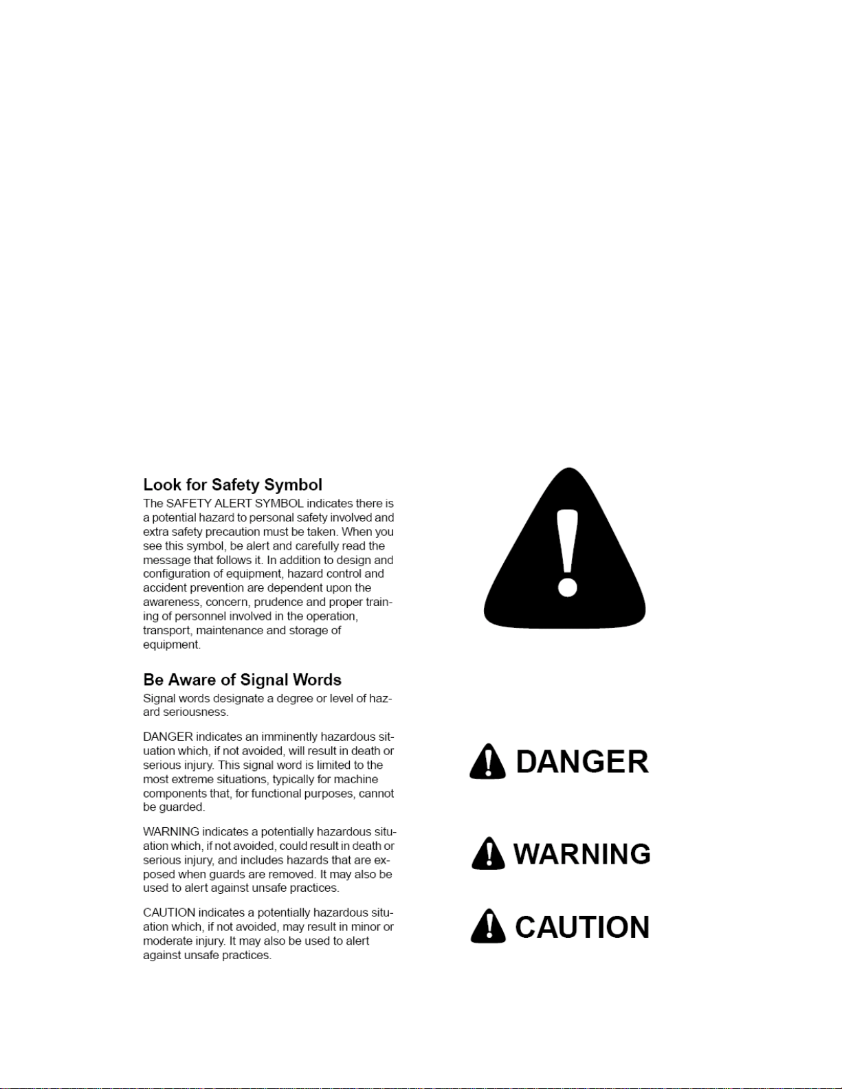
Safety
1-2
Page 3

OM17-P4000 Force/EC
Important! Read the following SAFETY PROCEDURES before operating the Veris
P4000
• Escaping fluid under pressure can penetrate the skin causing serious injury. Avoid
the hazard by relieving pressure before disconnecting hydraulic lines. Use a piece of
• Use paper or cardboard, NOT BODY PARTS, to check for suspected leaks.
• Wear protective gloves and safety glasses or goggles when working with hydraulic and
high-pressure wash systems.
• If an accident occurs, see a doctor immediately. Any fluid injected into the skin must
be surgically removed within a few hours or gangrene may result.
• Pinch point hazard: to prevent injury, stand clear when raising
or lowering any part of the Veris P4000.
• Install all transport locks before transporting or working underneath.
• Detach and store implements in an area where children normally do not play. Secure
implement by using blocks and supports.
• Keep feet clear of foot and probe when lowering.
• Do not probe where utility lines may be present. Use ‘Call Before You Dig’ services.
• Use paper or cardboard, NOT BODY PARTS, to check for suspected leaks.
• Wear protective gloves and safety glasses or goggles when working with hydraulic and
high-pressure wash systems.
• If an accident occurs, see a doctor immediately. Any fluid injected into the skin must
be surgically removed within a few hours or gangrene may result.
• Read Operations Manual before operating machine
• Review safety instructions with operators before operating machine and at least
annually
• Riders obstruct the operator’s view. They could be struck by foreign objects or
thrown from the machine.
• Never allow children to operate equipment.
• To prevent possible electrical shock, or damage to the instrument, do not connect to
any power source greater than twelve (12) volts DC.
• Do not grease or oil implement while it is in operation.
• Disconnect battery ground cable (-) before servicing or adjusting electrical systems or
before welding on implement.
• Remove buildup of mud, oil or debris.
• Be prepared if a fire starts
• Keep a first aid kit and fire extinguisher handy.
• Be careful when touching the probe after use, the sapphire window gets hot.
1-3
Page 4
OM17-P4000 Force/EC
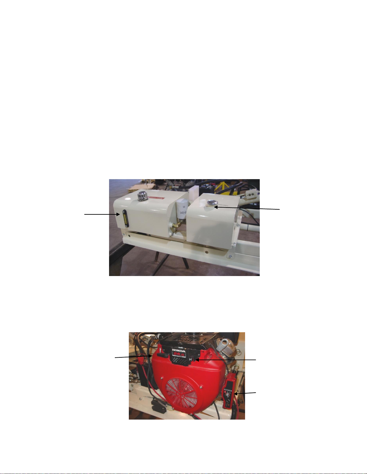
Hyd sight
gauge
Fuel Tank
Figure 1
Starter Switch
Choke
Throttle
Figure 2
Section 2
VERIS P4000 Probe Platform
System Overview
Before you begin using your P4000, it’s important to familiarize yourself with the basic
components and controls
Pre-operation checks:
1) Engine oil Level – refer to Honda GX 670 engine manual
2) Hydraulic fluid -- fluid level should be at or near upper black line on sight gauge
of hydraulic reservoir. (Figure 1). If not add suitable ISO 32 hydraulic fluid with a
viscosity index of 95- 140. Unit is filled at factory with Mobilfluid 424.
3) Check gas level – unleaded gasoline only
4) Check for any loose fasteners or hydraulic leaks.
Controls:
1) Engine controls are located on the engine itself. (figure 2) . Refer to Honda
engine manual for detailed information.
2-1
Page 5
OM17-P4000 Force/EC
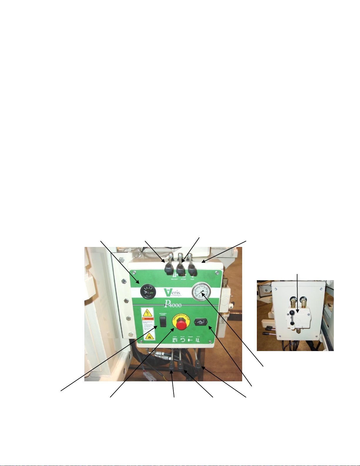
Figure 3
Figure 4
Voltage meter Side Shift control Extension control Fold control
Probe speed
Flow control
12v power switch Engine emergency stop Probe control Rotation control Foot control
Hyd pressure gauge
Engine hour meter
Hydraulic Controls
All system monitoring and probe control functions are contained on the
console mounted to the right of the probe, referred to as the “foot”. (Figures 3,4)
a) Voltage meter – monitors battery voltage
b) Side shift control – allows lateral movement of probe for multiple insertions at
a given location.
c) Extension control -- used to extend probe from transport to field use position
d) Fold control – folds probe from transport to use position
e) Probe speed flow control – controls insertion speed of NIR/EC Force Probe to
operator preference
f) Hydraulic pressure gauge – monitors system pressure during hydraulic
cycling
g) Hour meter—monitors engine operation for routine maintenance
h) Foot Control – Raises and lowers foot
i) Rotation control – aids in soil core insertion in tough soils. Down is clockwise-
direction required for coring.
j) Probe control – Raises and lowers probe assembly
k) Engine emergency stop – immediately shuts down engine if need arises.
l) 12VDC power switch for auxiliary and spectrometer power.
2-2
Page 6
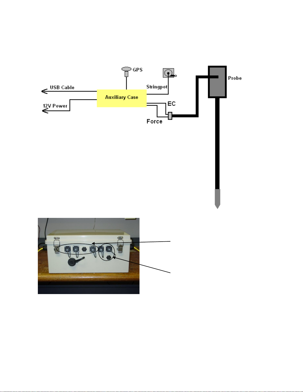
The first four connections are
only used with the VIS NIR
probe
Only these three connections
are used with the Force EC
probe
System diagram
OM17-P4000 Force/EC
Electronics
Figure 5
Figures 6
2-3
Page 7
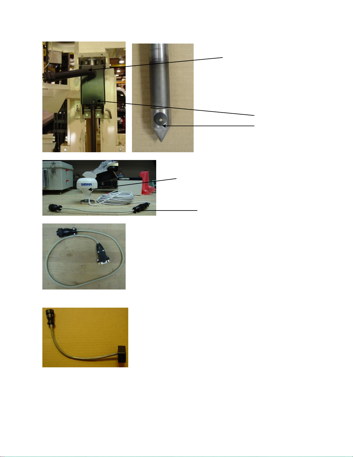
Figure 7&8
Probe module
#38145
Cable that includes force and EC
connections
Garmin GPS
# 21221
GPS adaptor cable #30727
Note: This adaptor cable is
required in order for
compatibility with the provided
Garmin GPS.
GPS serial adaptor cable
#35482
This will connect the serial port of a GPS to the
GPS port on the auxiliary case, for using an
alternate GPS to the Garmin. External power is
required for the GPS to function.
Figure 11 EC test load
#10447
OM17-P4000 Force/EC
Figure 9
Figure 10
2-4
Page 8
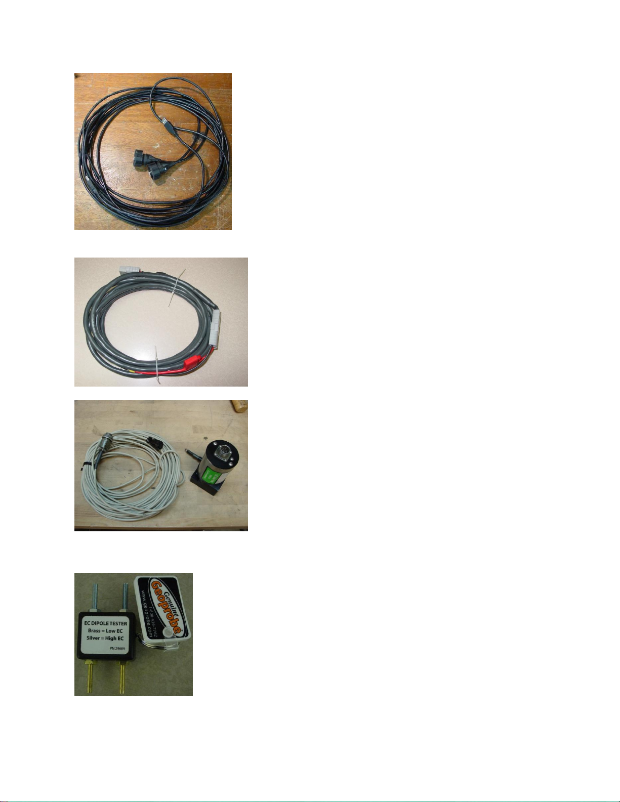
Figure 12
5-meter USB cable
#30281
Power cable
#39985
This is used to power the
instrument from a vehicle (for
field use).
Note: Only use 5-amp fuse
String Pot #SC160
String Pot Cable #38866
Figure 14
Figure 15 EC Dipole Tester #29689
OM17-P4000 Force/EC
Figure 13
2-5
Page 9
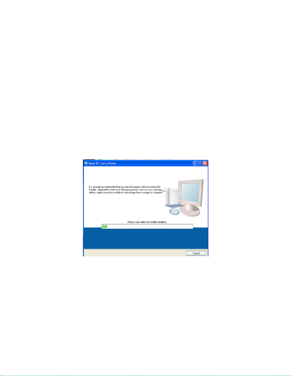
OM17-P4000 Force/EC
The Veris EC - Force
Software installer will
guide the user through
installation of the Veris
operating software and
the necessary drivers
needed to run the
Auxiliary case. Note:
Do not plug in USB
cable for case at this
time.
Section 3
Software Installation and Setup
Software Installation
Note: For computers outside the United States of America, please make the following
change to the computer’s regional settings before installing the Veris
Spectrophotometer Software.
Step 1: Open control panel and double click on Regional and Language Options
Step 2: Click on Customize, the following screen will appear. The Decimal symbol
needs to be a “.” while the Digit grouping symbol needs to be a “,”. The will ensure
proper operation of the software. Once the changes have been made click OK and
proceed with installation.
Veris EC - Force Software Installation
Figure 1
3-1
Page 10
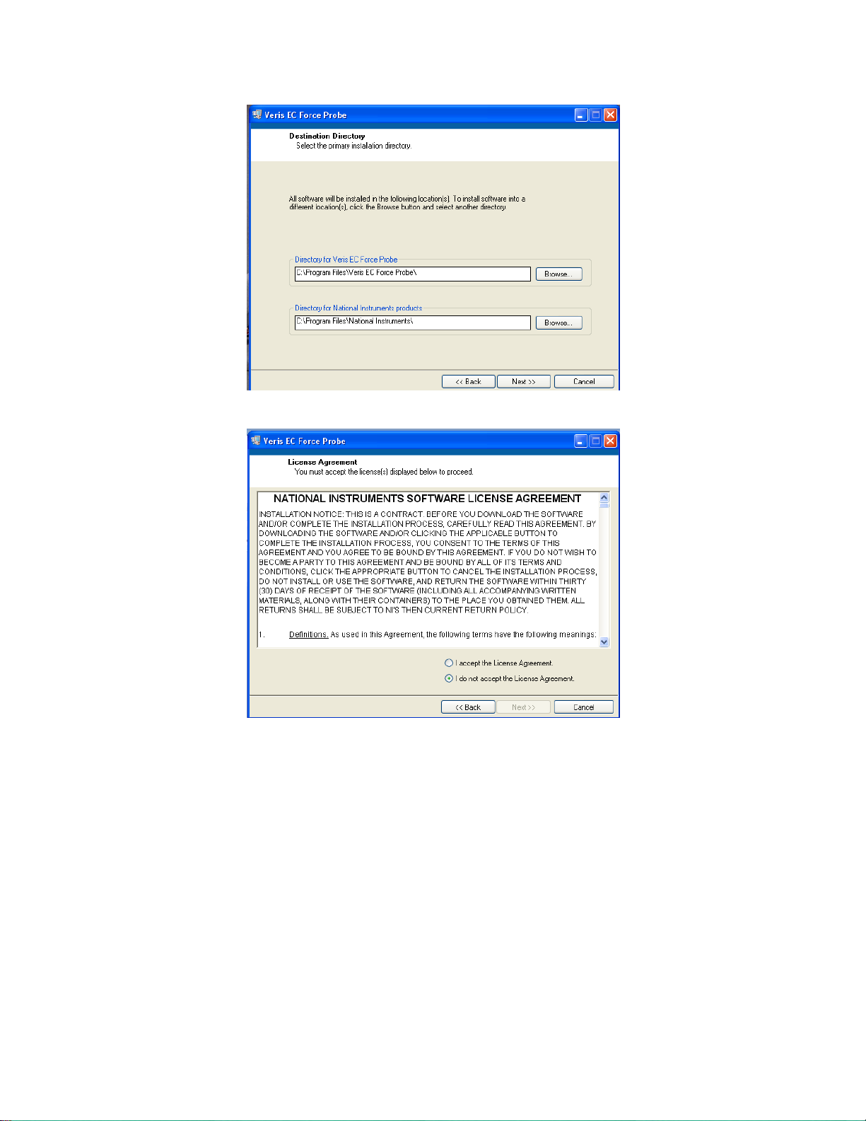
Figure 2
Only install
software in the
default directory.
If a different
directory is
chosen then the
auxiliary case
will not be able
to find the
correct drivers.
OM17-P4000 Force/EC
Figure 3
3-2
Page 11

Figure 4
Click next to install
software
Click finish to exit installer
Figure 5
Figure 6
OM17-P4000 Force/EC
3-3
Page 12

OM17-P4000 Force/EC
Any name or number can be used for
the file name
After typing name click save to
continue
Figure 1
Figure 2
Figure 3
Section 4
Field Operation - Electronics
The Force EC probe software will acquire a EC and force measurement for every 2cm
the probe is inserted. Before opening software turn on power to the auxilary case and
connect via USB cable to the PC. To begin data acquisition open the software and
select a file to be saved.
Once a file is selected the software will search for connectivity with the auxiliary case.
Three communication ports are used to process the data. After each connection is
established the corresponding light will turn green. If no connection is made, the
software will continue to the next port and try to establish a connection later. If no green
light is given for any of the three ports the software will not be able to aquire data. In
this senario, check for 12V to the case and ensure the USB cable is connected. If a
connection can still not be established, then unplug the USB cable, shut down power to
the instrument, and restart the software. If no connection is made still then unplug the
USB cable and restart the computer. Once the computer is back up, plug in the USB
cable and open the software again.
4-1
Page 13

OM17-P4000 Force/EC
Place the probe tip at the desired
starting point, check to ensure the
GPS signal light is green and press
log or hit Enter and begin to insert
the probe to store data. The log
light will turn green indicating the
software is in log mode. Data is
collected and averaged every 2cm.
Once the 2cm interval is reached
the data light will flash and the data
is written to the output file. Once the
desired depth is reached pull the
probe out and Log will be shut off.
The log button will need to be
pressed for again to start sampling
another location.
Depth will be -1
until log is
pressed.
The EC readings will give the
following error codes:
-1 = Low Current this condition
can occur when the probe is out
of the ground, or in dry soils
-2 = Low Voltage this condition
occurs when the dipole is
shorted. Check EC tip isolation
under the troubleshooting
section
-4 = High Voltage this condition
occurs when the dipole is open.
Check EC tip isolation under the
troubleshooting
Figure 4
.
4-2
Page 14

OM17-P4000 Force/EC
14” from rear edge
to rear of bumper
Section 5
Field Operation
P4000-S
Installation
The P4000-S is designed to be installed in ¾ ton – 1 ton pickups and due to the wide
range of bed and frame dimensions on the market, there are no mounting holes in lower
frame flange. Some drilling and fabrication will be required. You may choose to
perform this on your own, or may wish to have a local welding or truck shop do this for
you.
Steps:
1) Properly lift probe assembly in folded position with a minimum of two nylon straps
and lower into pickup bed.
2) Center side-to-side in bed and so rear portion of skid frame rail is 14” forward of
farthest point on rear bumper (Figure 1). This will ensure that foot will not contact
bumper when the skid is in the retracted position.
3) Ideally 4 mounting bolts (½” Gr5) are adequate for fastening the probe skid to the
frame of the truck. Choose mounting location based on frame obstructions such
as spring hangers, fuel tank hoses, etc. This will take some time, measuring both
top and underneath the bed to make sure bolts will align with skid frame
4) Locate all four positions and fabricate “L” straps from at least 3/8” material and
bolt or weld to frame. Make sure that fuel tanks, fuel line, and brake lines are not
in danger of being drilled or welded. Drilling is preferable and two ½” bolts in the
vertical position are adequate. (Figure 2)
Figure 1
5-1
Page 15

OM17-P4000 Force/EC
Figure 1
Figure 2A & B
Start out with ¼”
pilot hole for
drilling up through
Top View
Figure 3
Figure 4
“L” straps as templates, you can drill the hole through the bottom side of the skid
frame rail. Tip: If you start out with small pilot holes (1/4”or less) it takes less
effort to drill through the bed and frame rail, then drill out to full dimension from
on top.
6) If for some reason you must locate one or two of lower “L” mounts ahead or
behind the skid frame rail, you can fabricate some clips to hold down in place.
Ideally at least two bolts should go through the skid frame to ensure that probe is
properly connected to bed (Figure 3)
5) Using the
7) Securely bolt down and connect power cable to battery of vehicle.
5-2
Page 16
OM17-P4000 Force/EC
Figure 5
Figure 6
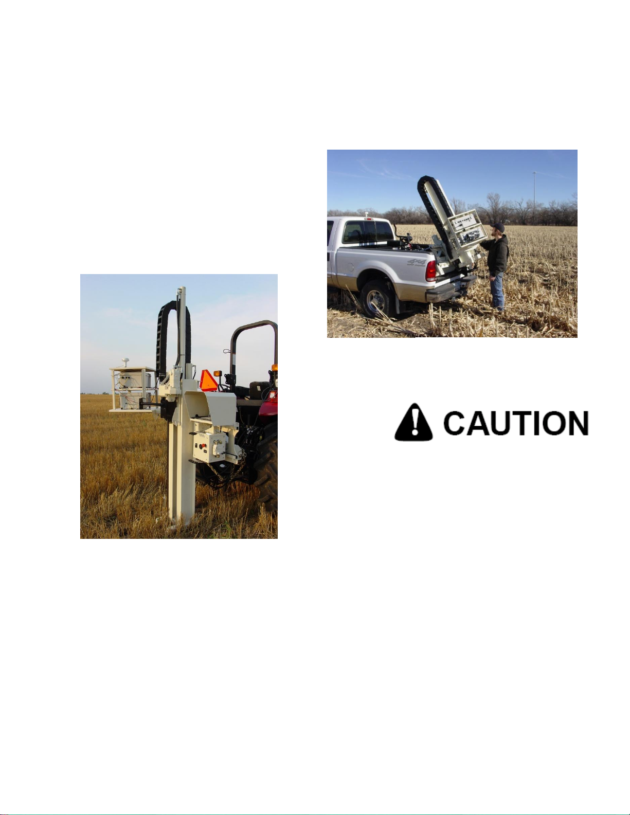
KEEP FEET CLEAR OF
FOOT AND PROBE
Field Operation
Probe Platform
- Start engine and allow to warm a minute or two before cycling – a few minutes if
during cold weather.
- Extend to full rear position
- Fold into upright position (figure 5)
- Lower foot to soil
- Raise probe (figure 6)
- Install Probe or core sampling
components
Important! -- When folding and retracting the platform make sure that
probe mast clears engine muffler. This can be achieved by shifting left to right as
you fold the unit.
5-3
Page 17

OM17-P4000 Force/EC
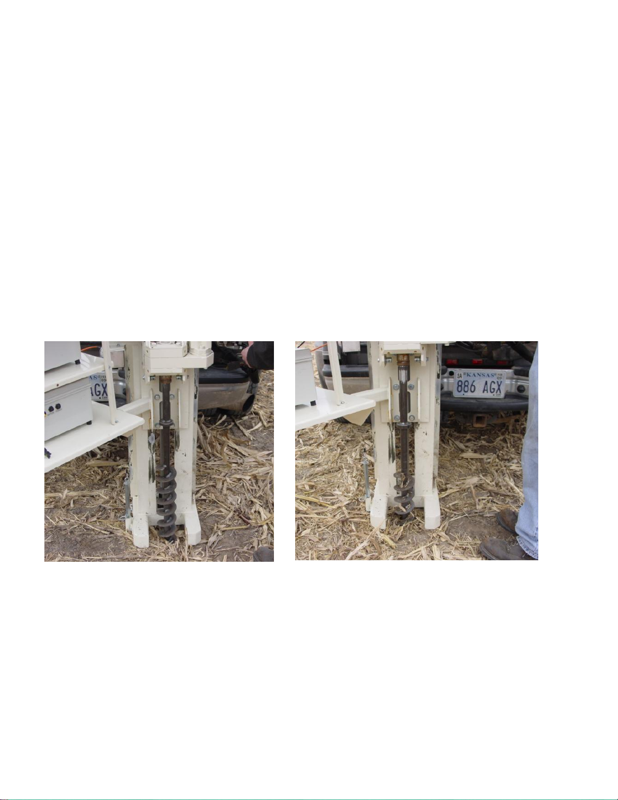
KEEP FEET CLEAR OF
FOOT AND PROBE.
Figure 7
Figure 8
Field Operation
EC - Force Probe
Checking Electrical Signal Continuity and Electrode Isolation
It is recommended that you routinely check the EC signal to verify that all functions are
working properly. See Maintenance and Lubrication Section for a step-by-step
procedure. It is advisable to perform this test on a routine basis (weekly or every 20-25
hours of data collection) to ensure you are obtaining reliable data.
Operation
Begin field operation by lowering the foot to the soil. Remove hairpin from string pot
piston (Figure 7) Set probe speed --- not recommended over 3cm/sec. This is
adjustable via the probe speed flow control on the side of the control panel. (Figure 9)
Lower the EC - Force Probe until the EC tip is at the desired starting point, usually just
below the surface of the soil. Press LOG in the EC – Force software to begin collecting
data. After reaching the desired depth pull probe out to stop logging data.
5-4
Page 18

OM17-P4000 Force/EC
Figure 9
Speed
Probe speed is not recommended over 30mm/sec, for optimal data resolution. This is
adjustable via the probe speed flow control on the side of the control panel. (Figure 9
above) A maximum probe speed of 50mm/sec should not be exceeded or else data
could be missing from the output file.
Field Condition
Field should be in a uniform state. Probe after intensive primary tillage is not
recommended. The soil must have a minimum of 10% available water, and cannot be
frozen.
Vehicle Requirements
The probe may be mounted on a variety of vehicles. The 3 point configuration allows
use on a 30-50hp tractor. While the optional skid platform requires a 4X4 pickup.
5-5
Page 19

OM17-P4000 Force/EC
Figure 10
Figure 11
Figure 12
Field Operations
Soil Coring
Once you have competed probing, remove EC - Force probe as outlined in Section 6.
- Install drive coupler to rotating head by means of drive retainer (Figure 10)
- Install PETG liner onto cutting shoe and thread into sampling tube (Figure 11)
- Install sampling tube into drive coupler and push into soil.
Use slow and steady insertion speed and minimal
rotation to push core sampler into the soil. A brief
rotation at bottom of stroke will snap off the core in
tight clay, giving you a fuller core as you retract.
(Figure 12) Excessive rotation may affect the
condition of your cores.
5-6
Page 20

OM17-P4000 Force/EC
Figure 13
Figure 14 Figure 15
Remove sampler tube and remove cutting shoe from sampling tube by tapping and
rotating, or by use of wrench (provided). (Figure 13)
Cap the lower end of core with black vinyl cap, and the top with red. (Figures 14-15)
5-7
Page 21
OM17-P4000 Force/EC
Figure 16
Figure 17
Field Operations
Optional Anchoring System
In some field conditions it may be necessary to drive soil anchors into the soil to obtain
adequate depth with probe or core sampler. If this is the case, you will need PN 40209
Anchoring Package.
Installation and Removal
- Retract probe until is in the most forward position.
- Side shift to the far right and lower foot.
- Place anchor in center of foot opening and lower probe drive until hex enters hex
drive on probe. (Figure 16)
- Drive in slowly using Probe and Rotation controls. Apply adequate force to push
as you rotate. If you rotate too rapidly, the anchor will simply auger a hole, and
will not anchor properly --- Drive in until all flighting is below ground level and
probe is at bottom of stroke.
- Raise foot, side shift to far left, and repeat this process. (Figure 17)
5-8
Page 22

1. Extend platform out to full extension
Figure 18
2. Attached chain binders on each side of probe
3. Slip anchor plates over anchors and bind down each side (figure 18)
OM17-P4000 Force/EC
- Anchoring will limit your side travel somewhat, but you should still be able to take
multiple cores with the anchors installed.
- Do not use extension control while anchors are connected
- Remove the anchors in reverse sequence.
- If anchors have shifted during use and you are unable to slide the hex head of
the anchor back into the hex drive – use the foot to gently nudge the anchor back
into re-alignment.
Note: Be careful when lowering the probe with the instrument cases in
place. Remove left hand anchor first – otherwise you might push the head
of the anchor into the instrument mount when lowering probe to remove
RH anchor.
5-9
Page 23

OM17-P4000 Force/EC
Figure 19 P & T Hoses
Figure 20
Field Operations
P4000T Removal and Tractor installation
The P4000 is designed to work equally well on a tractor, or as a skid mount unit.
Removing probe from skid –
- Install three point stabilizer stands into probe and temporarily lock in mid position
with ¾” pinch bolt.
- Extend and unfold the probe.
- Lower foot to ground level.
- Remove fold cylinder pin, and carefully retract fold cylinder until it is fully
retracted. You may have to gently move fold control valve back and forth to
relieve pressure on pin for removal.(Figure 19)
- Carefully remove lower link pins and lower probe down by retracting foot cylinder
- Lower stabilizer stands and lock with ¾” bolt
- Retract probe platform and shut of engine. (Figure 20)
- Disconnect wiring and 4 hoses on bottom of console (Figure 21)
- Disconnect main Pressure and Tank hose from platform (Figure 22)
5-10
Page 24

OM17-P4000 Force/EC
Figure 21
Fold and
Extend hoses
Disconnect
wiring
Figure 22
Installing on Tractor –
- All bushings and pins are provided for Category I and II three-point hitches.
- Connect lower links – make sure you include the stabilizer link bushings(Figure
24)
- Connect top link
- Raise three point to desired height and level with top link
- Install lower stabilizer mount on drawbar and tighten 5/8” bolts
- Connect LH and RH stabilizer to upper and lower points, adjust, and lock with
jam nut.
- Connect hydraulic hoses noting P and T
- Retract stabilizer stands and engage hydraulics -- locking valve into detent with
tarp strap or other device. Make sure that flow is correct or controls will be
backward.
5-11
Page 25

OM17-P4000 Force/EC
Figure 1
Section 6
Maintenance and Lubrication
Proper maintenance and lubrication of the Veris P4000G will allow you to collect high
quality EC and force, and greatly extend the useful life of the unit. Veris Technologies
strongly suggests that you follow the following guidelines:
MAINTENANCE: Storage of Auxiliary Instrument and EC – Force Probe
The auxiliary instrument and probe are water resistant; store system indoors or under
roof. Water damage to electronic components is not covered by warranty.
MAINTENANCE: Electrical Continuity and Isolation
It is advisable to perform this test on a routine basis (weekly or every 20-25 hours of
data collection) to ensure you are obtaining reliable data.
1) Probe electrode isolation – Check isolation of the dipole to the point with a
Digital Multi Meter if the dipole is properly isolated, a reading of 12K ohm
should be obtained.
6-1
Page 26

OM17-P4000 Force/EC
Test Load
Figure 3
Instrument EC Signal Testing – The Veris Auxiliary Instrument is shipped with an
Instrument Test Load (Part No. 10447) that will enable you to quickly check the
instrument to ensure that the EC circuit is functioning properly. To perform this test, do
the following:
1) Disconnect the signal cable from the amp pin (signal) terminal on the auxiliary
case.
2) Connect the test load to the signal terminal.
3) Turn on Auxiliary Instrument and start up software.
4) The display should show: (See Figure 3)
EC 193 +/-10
5) If the readings vary significantly (more than 10) contact Veris service
department.
6) Once the test is complete, remove the test load and reinstall the implement
signal cable.
Figure 2
6-2
Page 27

OM17-P4000 Force/EC
Figure 4
Figure 5
Probe EC Signal Testing – The EC – Force probe is shipped with a EC dipole tester
(Part No. 29689) that will enable you to quickly check the probe and instrument to
ensure the EC is functioning correctly. To perform this test, do the following:
1) Press one bolt of the dipole tester to the side of the probe tip and the other to
the center brass dipole. (see figure 5 below) Depending on if the brass or the
silver bolts are used the EC reading will be high or low. The high and low
readings may vary depending on contact with the probe tip and the probe tip
cleanliness. This is fine; the import thing is that the brass reading be lower
than the silver. The difference between the two readings will be hundreds of
EC values.
6-3
Page 28

OM17-P4000 Force/EC
Cables
Loom
Clip
Mounting
Pin
Probe Removal
This procedure is needed when removing the probe for bench top use, road transport,
or for soil coring.
Step 1:
Disconnect the force, EC, USB, and power cables to the auxiliary case.
Step 2:
Remove loom from clip.
Step 3:
Figure 6
Step 3:
Firmly grasp probe, and remove the mounting pin holding the probe on the platform.
6-4
Page 29

OM17-P4000 Force/EC
Auxiliary case
Mounting plate
Case Removal and Installation
When the auxiliary case needs to be removed for storage, repair, or bench top use
follow these instructions.
First disconnect all wires connected to the auxiliary case.
The case is secured with two latches, and case and latch assembly can be removed as
a unit.
Figure 7
Latches
Figure 8
6-5
Page 30

OM17-P4000 Force/EC
Section 7
Troubleshooting
Troubleshooting EC module
Data missing from display reading –
1. Unit must be in contact with soil to record data points
2. Check GPS and DGPS signal; Veris instrument is programmed to eliminate all nonDGPS geo-referenced points.
3. Shut power off and restart
4. Check electrical continuity
5. Check input voltage, 12 v minimum required
No GPS data is coming in during acquisition
1. Check to ensure nothing is obstructing GPS signal (ex. buildings)
2. Is the GPS plugged into the correct port? (second one from the right on auxiliary
case)
3. Check to make sure GPS adaptor is in place
4. Follow the steps of the GPS troubleshooting guide to further diagnose problem
Auxiliary data not updating or ports not setting up correctly
1. Shut down power, and restart cases
2. Unplug USB cables
3. Restart PC
4. Plug in USB cables and restart software
New hardware found wizard appears when I plug in my Auxiliary Instrument
1. Make sure the Veris EC – Force software has been installed properly.
2. If Veris EC – Force software has been installed, then proceed with the new hardware
found wizard. Use the provided Digi EdgePort driver disk and source for driver when
prompted by PC
7-1
Page 31

OM17-P4000 Force/EC
Troubleshooting GPS
If GPS fails to come in it could be for a variety of reasons. If using the provided Garmin
GPS make sure the GPS adaptor is in place (see figure 10 in system overview). Then
following troubleshooting tree to isolate the problem.
Figure 1
7-2
Page 32

OM17-P4000 Force/EC
Fuse holder. Replace only with a
4-amp fuse.
Fuse Replacement
The fuse for the auxiliary case protects the voltage for the electrical conductivity board
and the lamp. To replace the fuse open the case and locate the black fuse holder
Figure 2 Internal wiring of auxiliary case
7-3
Page 33

Section 8
WARNING: Damage to force sensor may occur if
this specification is exceeded
Specifications
Max ambient temperature to operate system: 110 degrees F
Max aux case temperature: 65 degrees C
Max aux case humidity: 90% RH
Max force sensor capacity: 22361 kPa or 3245 PSI
Max probe insertion speed: 50mm/s
OM17-P4000 Force/EC
8-1
 Loading...