

Page 1
TM
the user will be required to correct the interference at his own expense.
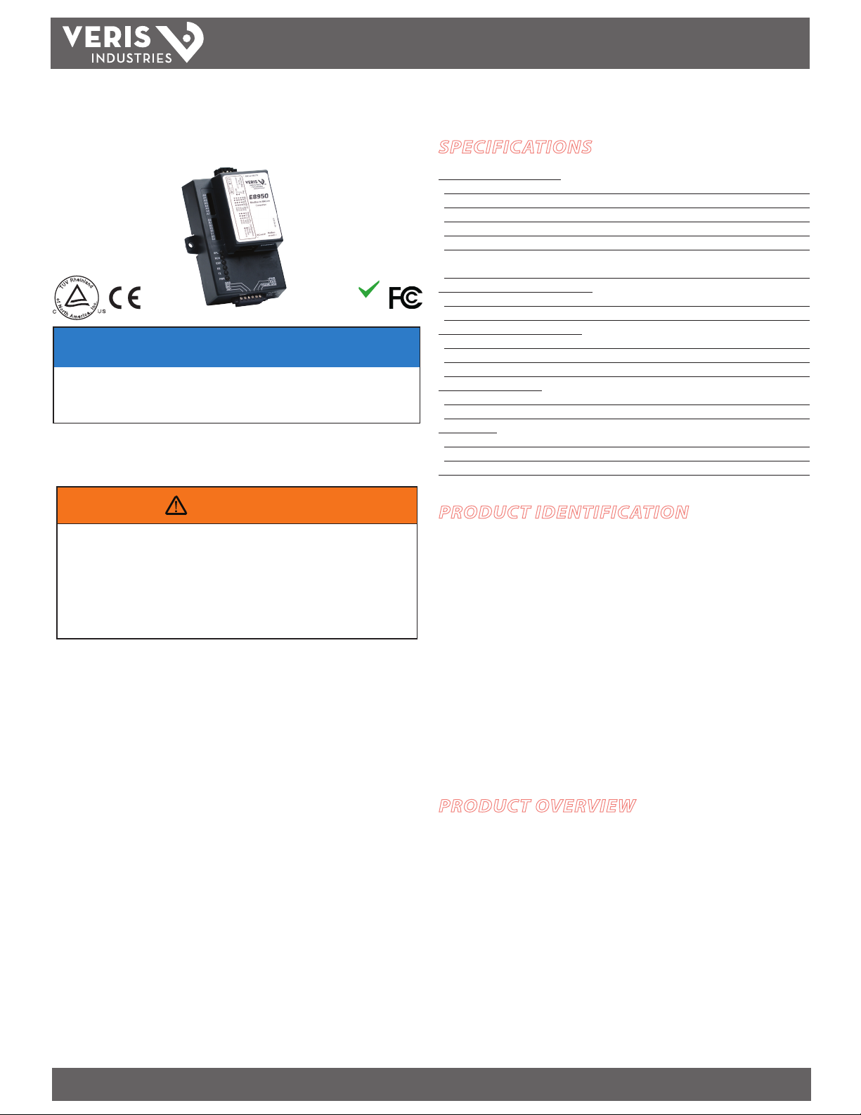
E8950
Modbus-to-BACnet Protocol Converter
e
h
i
n
R
l
a
V
n
d
U
T
o
f
.
N
NETWORK INTEGRATION
c
n
o
I
r
,
US
t
C
h
a
c
i
A
r
m
e
NOTICE
• This product is not intended for life or safety applications.
• Do not install this product in hazardous or classified locations.
• The installer is responsible for conformance to all applicable codes.
Control system design must consider the potential failure modes of control paths and, for
certain critical control functions, provide a means to acheive a safe state during and after a
path failure. Examples of critical control functions are emergency stop and over-travel stop.
RoHS
Compliant
INSTALLATION GUIDE
SPECIFICATIONS
Downstream (Device) Interfaces:
Physical Layer 2-wire RS-4 85
Line Termination Internal, 120 Ω
Line Polarization Internal
Protocol Modbus RTU
Baud Rate 9600 to 384 00 (selections var y with Modbus devices used)
Number of Devices Supported up to 32 devices
(not to exceed 1000 tot al BACnet data objects)
Upstream (Controller) Ethernet Interface:
Physical Layer 10/100 Mb Ethernet
Protocol BACnet IP
Upstream (Controller) Serial Interface:
Physical Layer 2-wire RS -485
Protocol BACnet MS/TP
Baud Rate 9600, 19200, 38400, and 7680 0
Input Power Requirements:
Supply Voltage Class 2 9-30VDC or 12-24VAC
Nominal Current Draw @ 12V 240mA
Environmental:
Operating Temperature Range -40°C to 122°C (-40°F to 50°F)
Operating Humidity Range 5-90% RH noncondensing
Agency Approvals CE; TUV approved to UL916
WARNING
LOSS OF CONTROL
∙ Assure that the system will reach a safe state during and after a control path failure.
∙ Separate or redundant control paths must be provided for critical control functions.
∙ Test the eect of transmission delays or failures of communication links.
∙ Each implementation of equipment using communication links must be individually
and thoroughly tested for proper operation before placing it in service.
Failure to follow these instructions may cause injury, death or equipment damage.
1
For additional information about anticipated transmission delays or failures of the link, refer to
NEMA ICS 1.1 (latest edition). Safety Guidelins for the Application, Installation, and Maintenance
of Solid-State Control or its equivalent in your specic country, language, and/or location.
Veris Industries assumes no responsibility for any consequences arising out of the use
of this material.
FCC PART 15 INFORMATION
NOTE: This equipment has been tested by the manufacturer and found
to comply with the limits for a class A digital device, pursuant to part
15 of the FCC Rules. These limits are designed to provide reasonable
protection against harmful interference when the equipment is
operated in a commercial environment. This equipment generates,
uses, and can radiate radio frequency energy and, if not installed and
used in accordance with the instruction manual, may cause harmful
interference to radio communications. Operation of this equipment in
a residential area is likely to cause harmful interference in which case
Modifications to this product without the express authorization of
Veris Industries nullify this statement.
1
PRODUCT IDENTIFICATION
E8950 Modbus-to-BACnet Protocol Converter
Supported Veris Meters***: H8035, H8036, E50C2,
E50C3*, E51C2, E51C3*, H81xx Series (with the
H8163-CB Modbus RTU Communication Board), H8238
Series, H8436 Series, H8437 Series, and E30Ax42**,
E30Bxxx**, E30Cxxx**, E31Bxxx**, E31Cxxx** Series
* The E8950 does not support the logging fu nctionality of these meters.
** Must include rmware version 1.011 or later.
*** E31A42 is suppor ted also, but requires some manua l conguration. Contact Veris Customer
Support for details.
Refer to Appendix 3 to determin e how many meters of each type can be supported.
PRODUCT OVERVIEW
The E8950 is a protocol conversion gateway that adapts supported Veris Modbus
RTU energy meters to building automation systems using BACnet protocol over
either IP or MS/TP physical layer interfaces. The E8950 supports up to 32 meters or
1000 total measurement points (number of output points varies by meter model). It
is pre-programmed to discover any supported meters and automatically congure
them for BACnet MS/TP and BACnet/IP. Each Modbus meter is presented as a BACnet
device, with a unique BACnet device_ID and a full set of measurement data and
conguration objects. Little conguration is required. The user sets up the system
using DIP switches and a built-in webserver graphical user interface (GUI).
ZL0105-0B PAGE 1 ©2013 Veris Industries USA 800.354.8556 or +1.503.598.4564 / support@veris.com 02131
Alta Labs, Ene rcept, Enspector, Hawk eye, Trustat, Aerospon d, Veris, and the Veris ‘V ’ logo are tradem arks or registe red trademarks o f Veris Industries, L .L.C. in the USA and/or ot her countries.
Page 2
E8950
TM
INSTALLATION GUIDE
TABLE OF CONTENTS
Dimensions 2
Quick Install 2
Product Diagram 3
LED Blink Codes 3
Installation 3
BACnet Programming Information 8
Troubleshooting 9
China RoHS Compliance Information 9
Appendix 1: Data Objects for Supported Metering Devices
Enercept H8035 Series Meter 10
Enercept H8036 Series Meter 11
E50C2 and E50C3 (without logging) Uni-Directional Meter 12
E51C2 and E51C3 (without logging) Bi-Directional Meter 15
H8436 Series Meter 20
H8437 Series Meter 21
H8238 Multi-Circuit Meter 24
H8163 Energy Meter with H8163-CB Modbus Communication Board 28
E30A042, E30A142 Branch Circuit Power Meter 31
E30Bxxx, E30Cxxx, E31Bxxx, E31Cxxx Branch Circuit Power Meter 62
Appendix 2: DIP Switch Address Settings 81
Appendix 3: Quick Guide to Calculate the Number of Meters Supported 83
QUICK INSTALL
1. Connect the Modbus outputs of the metering devices to the Modbus terminals on
the 6-pin connec tor of the E8950. Daisy chain up to 32 metering devices to the
E8950 (provided that the total number of data points from all devices does not
exceed 1000).
2. Connect 9-30 VDC or 12-24 VAC to the power terminals on the 6-pin connector.
3. Use DIP switches S0 to S2 to set the Modbus baud rate on the E8950 to the same
rate as on all metering devices in the chain (factory default is 9600 baud).
4. Use DIP switch A7 to select the BACnet physical layer (MS/TP or IP).
5. If using BACnet MS/TP, connect the MS/TP connections to the BACnet interface.
Use DIP switches A0 to A6 to set the MAC address, and use DIP switches B0 to B3 to
set the MS/TP baud rate (factory default is 76800).
6. If using BACnet/IP, connect the E8950 to a PC using an ethernet cable and use the
GUI to set the IP address.
7. If the default network number (50) or the default Device_ID oset will cause
conicts, connect the E8950 to a PC using an ethernet cable and use the GUI to set
them appropriately.
8. Apply power to the E8950 and allow time to map all Modbus devices in the chain.
9. If the conguration is nal and will not change (no Modbus devices will be added,
removed, or changed), set the conguration mode to Normal (slide DIP switch A7
to the right) to speed future power-up cycles and prevent the auto-conguration
mechanism from overwriting when power is cycled.
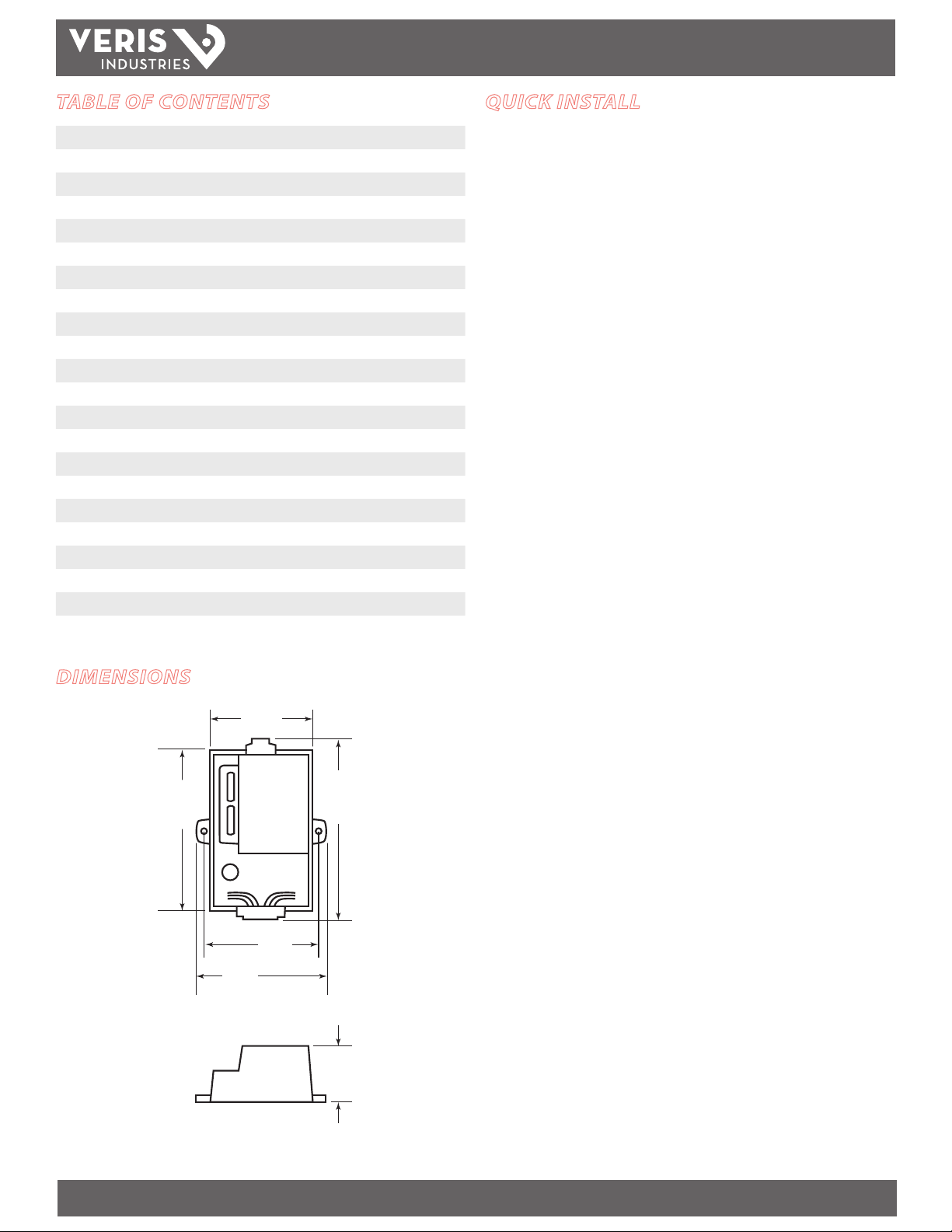
DIMENSIONS
4.5”
(115 mm)
2.9”
(74 mm)
5.1”
(129 mm)
3.25”
(83 mm)
3.6”
(92 mm)
1.6”
(41 mm)
ZL0105-0B PAGE 2 ©2013 Veris Industries USA 800.354.8556 or +1.503.598.4564 / support@veris.com 02131
Alta Labs, Ene rcept, Enspector, Hawk eye, Trustat, Aerospon d, Veris, and the Veris ‘V ’ logo are tradem arks or registe red trademarks o f Veris Industries, L .L.C. in the USA and/or ot her countries.
Page 3
E8950
TM
PRODUCT DIAGRAM
BACnet MS/TP RS-485
DIP switches for setting MS/TP
MAC address, physical interface
type, MS/TP baud rate, Modbus
baud rate, and enabling auto-
discovery of meters
BACnet
IP/Ethernet
Port
Modbus RTU port RS-485 +, -, Shield
Power 9-30 VDC, 12-24 VAC
LED BLINK CODES
LED Color Description
SPL Blue Reserved for future use. It may be on or o when the unit is on.
RUN Dark Green Slow blink (one second on, one second o) after the product
ERR Red • This illuminates blink briey when the Run LED rst comes on
RX Yellow Indicates the device is receiving data on the Modbus link.
TX Orange Indicates the device is transmitting data on the Modbus link.
PWR Light Green This is always on when the unit is powered.
has initialized (approximately 40 seconds after the unit is
powered or reset). This indicates normal operation.
(about 15 seconds after the unit is powered or reset).
• A steady red light indicates the unit needs attention.
INSTALLATION GUIDE
2. Connect the Modbus outputs of the devices to the Modbus side of the E8950.
120 Ω resistor on the last device in the daisy chain.
+
–
S
E8950 Meters
• Wire the RS-485 bus as a daisy chain from device to device (up to 32
supported devices) without any stubs. Use a 120 Ω termination resistor
(not included) on the device farthest from the E8950. An additional 120 Ω
termination and Modbus line polarization are provided internal to the
E8950.
• Connect shield to earth ground somewhere on the RS-485 bus. The shield
is not internally connected to earth ground.
• Use wire with an insulation rating sucient for the location where the
meter is installed (e.g. Belden 1120A for installation in panels with up to
60 0 VAC).
3. Connect 9-30 VDC or 12-24 VAC to the +PWR/-PWR terminals of the 6-pin
connector.
Modbus Setup
Use DIP switches S0 to S2 to set the Modbus baud rate to 9600, 19200, or 38400. The
default baud rate is 9600, because this rate is available on all the devices supported
by the E8950. If all connected devices support a faster rate, use the highest rate in
common to improve performance. Set the E8950 and all Modbus
devices in the series to the same rate. Set all devices to NO parity.
INSTALLATION
The E8950 can be DIN rail mounted, using the supplied DIN rail mounting clip, or
screw-mounted directly to a wall or other at sur face using the mounting holes on
either side of the housing.
6 Pin Connector
Pin # Pin Assignment
Pin 1 RS-485 + (Modbus)
Pin 2 RS-485 - (Modbus)
Pin 3 RS-485 GND
Pin 4 V +
Pin 5 V -
Pin 6 FRAME GND
1. Refer to the Installation Guides for the specic meter devices used to locate
instructions on connecting the meters and changing the conguration settings.
Modbus Power
Baud Rate S0 – S2 DIP Switches
S0 S1 S2
9600 Baud
19200 Baud
38400 Baud
BACnet Physical Layer Selection
Use DIP switch A7 to select the BACnet physical layer. See
Appendix 2: DIP Switch Addresses section at the back of this
document for physical layer switch settings.
Layer Switch Position
BACnet/IP
BACnet MS/TP
ZL0105-0B PAGE 3 ©2013 Veris Industries USA 800.354.8556 or +1.503.598.4564 / support@veris.com 02131
Alta Labs, Ene rcept, Enspector, Hawk eye, Trustat, Aerospon d, Veris, and the Veris ‘V ’ logo are tradem arks or registe red trademarks o f Veris Industries, L .L.C. in the USA and/or ot her countries.
Page 4
E8950
TM
INSTALLATION GUIDE
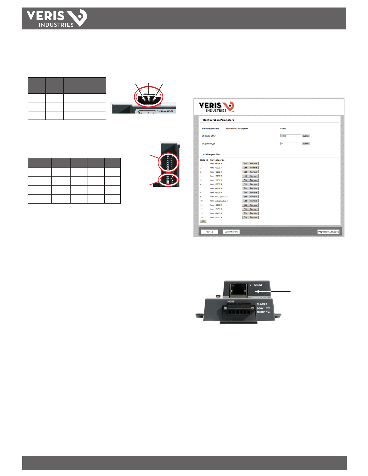
MS/TP Setup (if using BACnet/IP, skip this section)
1. Connect the MS/TP connections on the E8950 to the eld controller or other
BACnet MS/TP interface according to its guidelines.
Pin
Pin # Pin assignment
Label
+ Pin 1 RS-485 + (MS/TP)
- Pin 2 RS-485 - (MS/TP)
G Pin 3 RS-485 Shield
2. Set the MAC address using DIP switches A0-A6. See Appendix 2: DIP Switch
Addresses section at the back of this document for a full table of valid address
switch settings.
3. Set the MS/TP baud rate using DIP switches B0-B3.
Baud B0 B1 B2 B3
9600
19200
38400
76800
G (Shield) – +
MAC
Address
Baud
Rate
Accessing the Graphical User Interface (GUI)
If the E8950 IP address parameters are already congured to work on the network
and the E8950 is being accessed from a PC on that same network, open a web
browser and enter the IP address of the E8950 into the address/URL led on the
browser. Press enter. The GUI will launch and appear, as shown, in the browser
window.
If the E8950 IP address parameters are not congured for the network, connect a PC
directly and access the GUI from it as follows:
4. Connect a standard CAT5 ethernet cable between a PC and E8950.
Ethernet/BACnet IP
port location
ZL0105-0B PAGE 4 ©2013 Veris Industries USA 800.354.8556 or +1.503.598.4564 / support@veris.com 02131
Alta Labs, Ene rcept, Enspector, Hawk eye, Trustat, Aerospon d, Veris, and the Veris ‘V ’ logo are tradem arks or registe red trademarks o f Veris Industries, L .L.C. in the USA and/or ot her countries.
Page 5
E8950
TM
INSTALLATION GUIDE
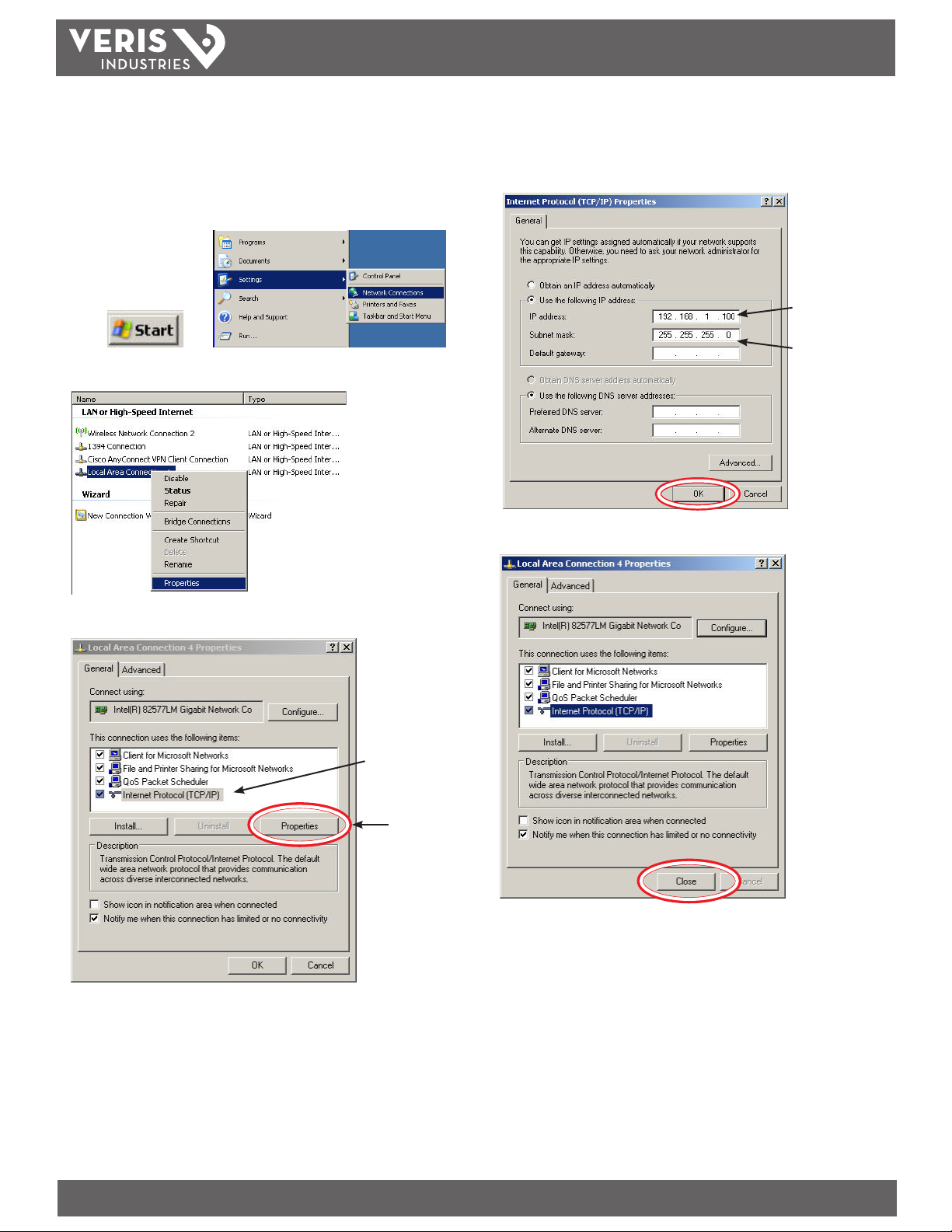
5. Temporarily change the IP address of the PC to a static value on the same subnet
as the E8950. For example: If the E8950 is set to its factory default IP address of
192.168.1.24, set the PC to an unused static IP address on the 192.168.1.xxx subnet
(where xxx is any value between 1 and 255, except 24). Set the subnet mask to
255.255.255.0 (the screen captures in this example were taken using Windows XP;
other operating systems will look dierent).
a. Click , then
b. Right-click on the local area connection you are using and select Proper ties
d. Select <Use the following IP Address>. Make note of the IP address that
appears, then enter the static IP address (e.g. if the E8950 is still set to its
default address of 192.168.1.24, then change it to 192.168.1.100). Enter for the
255.255.255.0 subnet mask. Click OK.
Enter static
IP address
Enter subnet
mask
e. Click Close.
c. Highlight Internet Protocol (TCP/IP) and select Properties
Select protocol
Click Properties
6. Open a PC web browser and enter the IP address of the E8950 (default address
is 192.168.1.24) to access the E8950 GUI. The GUI will launch and appear in the
browser window.
7. When nished using the GUI, unplug the ethernet cable from the PC and restore
the IP settings as needed.
ZL0105-0B PAGE 5 ©2013 Veris Industries USA 800.354.8556 or +1.503.598.4564 / support@veris.com 02131
Alta Labs, Ene rcept, Enspector, Hawk eye, Trustat, Aerospon d, Veris, and the Veris ‘V ’ logo are tradem arks or registe red trademarks o f Veris Industries, L .L.C. in the USA and/or ot her countries.
Page 6
E8950
TM
INSTALLATION GUIDE
Using the GUI to Set the E8950 Internal Network Number or the Device_ID
Offset
Access the GUI according the instructions in the “Accessing the Graphical User
Interface (GUI)” section.
The home screen on the GUI shows the current values used for the oset used to
assign Device_IDs in discovery mode and the network number assigned to the
internal virtual network used by the E8950 to manage the Modbus devices attached.
Using the GUI to set up the E8950 IP address for use on your network
1. Access the GUI according the instructions in the “Accessing the Graphical User
Interface (GUI)” section. To set IP address parameters, click the button labeled
“Diagnostics and Debugging.”
The Diagnostics screen appears.
The oset used to assign Device_IDs in discovery mode is the variable labeled BN_
Node_Oset. Enter a dierent value here and click submit. The new value is rst used
at the next power-up or system restart. Valid Device_ID numbers range from 1 to
4194303. Since the numbers assigned during discovery are the sum of the Oset and
the Modbus address (which can be any value from 1-255), the Oset values entered in
the GUI must be less than 4194057.
The internal virtual network used by the E8950 to manage the Modbus devices
attached is the variable labeled BN_Network_Nr. Enter a dierent value here and
click submit. Valid network numbers range from 1 to 65534; if other values are
entered, the network number defaults to 5. The new value is rst used at the next
power-up or system restart. If using a BACnet router, it is recommended that the
router also be restarted after the E8950 has completed discovery, when the network
number is changed.
2. Have the desired IP settings ready in advance (contact the system administrator).
IP parameters for use with BACnet IP are static, not dynamic.
3. Set the IP address for use on the BACnet/IP network:
a. From the navigation tree (lef t column) on the GUI, click on Setup and then
Network Set tings to enter the Edit IP Address Settings menu.
b. Enter the desired IP address in the N1_IP_Address eld (in the format xxx.xxx.
xxx.xxx)
c. If necessary, change the Subnet Mask by entering the appropriate new value in
the N1_Netmask eld
ZL0105-0B PAGE 6 ©2013 Veris Industries USA 800.354.8556 or +1.503.598.4564 / support@veris.com 02131
Alta Labs, Ene rcept, Enspector, Hawk eye, Trustat, Aerospon d, Veris, and the Veris ‘V ’ logo are tradem arks or registe red trademarks o f Veris Industries, L .L.C. in the USA and/or ot her countries.
Page 7
E8950
TM
INSTALLATION GUIDE
d. If the E8950 is connected to an ethernet gateway, enter its IP address in the
Default Gateway eld.
e. Click the Update IP settings button. The E8950 will change its settings and
restart. The GUI will not connect again until the E8950 is installed on the network
that matches those settings and the new IP address is entered into a web browser
on a PC properly congured for that network.
Profile Assignment
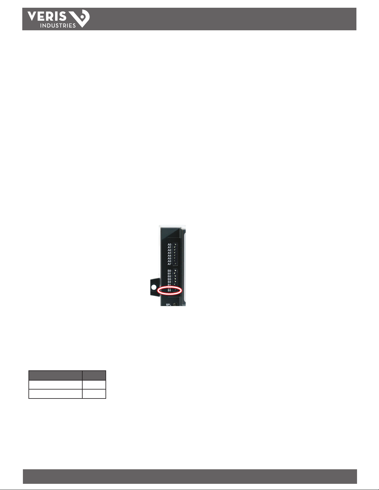
Prole assignment is automatic. Upon power-up/reset, with the device in Discovery
mode (DIP switch S3 is to the right), each Modbus address is queried for a slave ID.
Any devices that respond with a slave ID matching a supported device are given a
unique device object and a full set of data objects to match the device.
All supported Veris meters are discovered and assigned one of the proles (see
Appendix 1) if they are connected, powered, and congured properly.
The Add/Remove/Edit buttons on the GUI can be used to alter the assignments,
but this is not recommended for general use, as the proles could be assigned to
products they do not support. If a meter is not discovered because it is not connected,
powered, or congured properly, adding the prole manually will not make it work.
Any changes to the prole assignments made manually through the GUI will be
discarded when the E8950 is power-cycled or reset in Discovery mode.
Turn on the E8950
1. Set the conguration mode switch (S3) to the Discovery
position.
2. Apply power to the E8950. It can take up to 2-3 minutes to
discover all the Modbus RTU meters, build a conguration
le, and install the device on BACnet MS/TP. Scanning begins
at address 1 and continues in numerical sequence, mapping
meters as they are discovered. To shorten this time, use
lower Modbus addresses for the meters so that they will be
discovered and mapped more quickly. After the meters at the
lower addresses are discovered, the E8950 continues scanning
the remaining addresses in the background, without aecting
operation.
BACnet Network Management – Important Steps to Avoid Conflicts
BACnet conguration uses two default settings that might need to be changed,
depending on the application.
a. Network ID number. Every logical network segment (IP subnet, MS/TP trunk, etc.)
in an entire system must have a (16-bit) network ID number that is unique from
all other BACnet networks in the enterprise. The BACnet network administrator
assigns this network ID so that no two ID numbers conict (whether using
BACnet/IP or MS/TP). Within each segment, every device is physically identied by
the combination of its 8-bit MAC address and the 16-bit network ID number.
To support multiple meters with a single E8950, the E8950 presents multiple
BACnet devices using a single (its own) MAC address. Each E8950 has its own
(internal) network ID, and it assigns a unique MAC address to each Modbus meter
attached, derived from the unique Device_IDs.
The E8950 factory default network address is 50 (decimal). If that number is
already in use in the system, assign a unique address using the graphical user
interface (GUI) on the built-in web server (this requires an ethernet connection
to a web browser; see BACnet/IP Setup section for instruc tions on changing
conguration settings using the GUI). Valid network numbers range from 1 to
65534; if other values are entered, the network number defaults to 5.
b. Device ID. Every BACnet device must have a BACnet Device_ID number that is
unique throughout the entire enterprise. Since the E8950 presents every Modbus
meter as a BACnet device, each connected meter that has a Modbus address must
have a BACnet Device_ID.
By default, each device discovered receives a Device_ID number that is the sum
of an oset value (default is 50000) and the Modbus address of the device. If
these Device_ID numbers cause a conict with existing devices in the system, or
if the system includes multiple E8950s, change the Device_ID numbers before
connecting the E8950 to the system. This can be managed one of two ways:
i. Connect to the E8950 directly (oine from the system) with the devices
(meters) connected to the E8950. After the E8950 discovers the devices
and assigns their default ID numbers, the user can choose new Device_ID
values and write these to each device using BACnet software. Subsequent
discoveries will not overwrite these values with defaults even if the E8950 is
then set to Discovery mode.
3. Optional: Lock the conguration. If no more devices will be added to or removed
from the Modbus trunk, lock the device mapping by setting the mode from
Discovery to Normal (slide DIP switch S3 to the left). This causes the E8950 to
set up the same devices at power-up, without repeating the Discovery process.
In Normal mode, the power-up time improves, but BACnet devices are created
whether the device responds or not, and new devices are not discovered.
ii. Use the GUI on the built-in web server to modify the oset value used
to calculate default Device_IDs in the discovery process (this requires an
ethernet connection to a web browser; see BACnet/IP Setup section for
instructions on changing conguration settings using the GUI). The E8950
retains this oset value and uses it to assign Device_ID numbers ever y time
power is cycled if the E8950 is in Discovery mode. Valid Device_ID numbers
range from 1 to 4194303. Since the numbers assigned during discovery are
Configuration Mode S3
Normal
Discovery
the sum of the Oset and the Modbus address (which can be any value from
1-255), any Oset values entered in the GUI must be less than 4194057.
Determine the best mode for the application. Discovery mode queries and rediscovers devices each time the E8950 is power-cycled or reset, so use this mode
when you anticipate adding, removing, or changing Modbus devices. Normal
mode creates the same set of BACnet device objects when the E8950 is powercycled or reset, even if objects change, are removed, or cease to communicate.
Power-up time is faster in Normal mode.
ZL0105-0B PAGE 7 ©2013 Veris Industries USA 800.354.8556 or +1.503.598.4564 / support@veris.com 02131
Alta Labs, Ene rcept, Enspector, Hawk eye, Trustat, Aerospon d, Veris, and the Veris ‘V ’ logo are tradem arks or registe red trademarks o f Veris Industries, L .L.C. in the USA and/or ot her countries.
Page 8

E8950
TM
BACNET PROGRAMMING INFORMATION
INSTALLATION GUIDE
BACnet PICS (Protocol Implementation Conformance Statement)
Vendor Name: Veris Industries
BACnet Vendor ID 133
Product Name: E8950 Modbus-to-BACnet Protocol Converter
Product Model Number: E8950 w/Modbus Energy Meter
Product Description: Modbus-to-BACnet Protocol Converter
Protocol Conversions: Converts Modbus RTU to BACnet IP and BACnet MS/TP for supported products from Veris Industries
BACnet Protocol Version: Version 1 Revision 12
BACnet Standardized Device Prole (Annex L) – [Note: E8950 is a gateway device]
• BACnet Application Specic Controller (B‐ASC)
BACnet Interoperability Building Blocks Supported (Annex K):
• K.1.2 BIBB ‐ Data Sharing ‐ ReadProperty‐B (DS‐RP‐B)
• K.1.4 BIBB ‐ Data Sharing ‐ ReadPropertyMultiple‐B (DS‐RPM‐B)
• K.1.8 BIBB ‐ Data Sharing ‐ WriteProperty‐B (DS‐WP‐B)
• K.1.10 BIBB ‐ Data Sharing ‐ WritePropertyMultiple‐B (DS‐WPM‐B)
• K.1.12 BIBB ‐ Data Sharing ‐ COV‐B (DS‐COV‐B)
• K.2.2 BIBB ‐ Alarm and Event‐Notication Internal‐B (AE‐N‐I‐B)
• K.2.5 BIBB ‐ Alarm and Event‐ACK‐B (AE‐ACK‐B)
• K.2.11 BIBB ‐ Alarm and Event‐Information‐B (AE‐INFO‐B)
• K.5.2 BIBB ‐ Device Management ‐ Dynamic Device Binding‐B (DM‐
DDB‐B)
• K.5.4 BIBB ‐ Device Management ‐ Dynamic Object Binding‐B (DM‐DOB‐B)
• K.5.6 BIBB ‐ Device Management ‐ DeviceCommunicationControl‐B (DM‐
DCC‐ B)
• K.5.12 BIBB ‐ Device Management ‐ TimeSyncronization‐B (DM‐TS‐B)
• K.5.22 BIBB ‐ Device Management – List Manipulation‐B (DM‐LM‐B)
Standard Object Types Supported
• Device Object
• Analog Input
• Analog Output*
• Analog Value
• Binary Input*
• Binary Output*
• Binary Value*
• Multi State Input*
• Multi State Output*
• Multi State Value*
• Notication Class Object*
* Supported by device driver, but not used by current device proles
Unsupported Properties and Restrictions
• Does not support BACnet CreateObject
• Does not support BACnet DeleteObject
• Does not support any proprietary properties
• No proprietary properties exist
• No range restrictions exist
• Max_Master is writable, but it reverts to 127 when the E8950 is reset or
powered-up.
Data Link Layer Options:
• BACnet IP, (Annex J)
• MS/TP master (Clause 9), baud rate up to 76.8 kbps
Networking Options:
• BACnet/IP Broadcast Management Device (BBMD)
• Registrations by Foreign Devices
Character Sets Supported:
• ISO 10646 (UTF-8) / ANSI X3.4
General Programming Information
The E8950, in Discovery mode, queries each Modbus address, from 1 to 247 for a slave
ID. For each address queried, if a meter responds with a slave_ID that matches those
supported by the E8950, a BACnet device object and a full set of data objects are
created (see Appendix 1).
The initial Object_Identier (Device_ID) property value of each device objec t
discovered is the sum of the Device_ID oset programmed into the E8950 and the
Modbus address of the meter. The factory default value of the oset is 50000; use
the GUI to change this value. The new value will be applied the next time the E8950
is power cycled or reset. Once a device’s Object_Identier is overwritten, changes
to the ID Oset will no longer aect that Object_Identier, even in Discovery mode.
Make further changes to the value by writing the Object_Identier property.
The default Object_Name property value of each device object is an abbreviated
name of the meter series discovered with an underscore and the Modbus address of
the meter appended to it. The Object_Name is a writable property. Once a device’s
Object_Name is overwritten, the Object_Name will not rever t to the initial default,
even in Discovery mode. Make fur ther changes to the value by writing the Object_
name property.
The default description property value of each device object is the rst 40 characters
of the Modbus slave ID returned by the meter discovered. The description is not a
writable property.
The E8950 supports Subscribe_COV, with default COV increment values assigned
as shown in the data object tables (see Appendix for value tables for each meter).
If these values are not appropriate for a specic application, write them as needed
when they are subscribed. On subsequent power c ycles, no subscriptions are active
and the COV increments return to their default values.
With few exceptions, any data values written to AV objects are accepted (without
error) by the data object and passed through to the corresponding Modbus register.
There is no direct indication via the BACnet protocol if invalid values are rejected.
After an invalid value is written to the Present_Value of an AV, subsequent reads
of that propert y return the new (invalid) value until the next time the E8950 scans
and updates the AV objects (this may take several seconds, depending on the overall
conguration and timing of the scan sequence). The tables in Appendix 1 specify valid
values for AV objects of each supported model.
ZL0105-0B PAGE 8 ©2013 Veris Industries USA 800.354.8556 or +1.503.598.4564 / support@veris.com 02131
Alta Labs, Ene rcept, Enspector, Hawk eye, Trustat, Aerospon d, Veris, and the Veris ‘V ’ logo are tradem arks or registe red trademarks o f Veris Industries, L .L.C. in the USA and/or ot her countries.
Page 9
E8950
TM
TROUBLESHOOTING
Problem Solution
Use the main screen of the E8950 GUI to conrm which meters have been discovered.
Verify that the Modbus device is a model specically supported by the E8950 (see Appendix 1).
Verify that the meter is connected to a control power source and is operating normally.
Verify that the Modbus 2-wire RS-485 connection is correctly wired from the E8950 to all
Modbus device is not discovered as expected.
other Modbus devices and that the chain is terminated at both ends with 120 Ω resistors (not
included).
Verify that the Modbus RTU baud is set to the same rate on all Modbus devices and that parity
on all devices is set to “none.”
Verify that the E8950 is powered and operating (the light green LED is on).
Verify that the E8950 is in Discovery mode.
CHINA ROHS COMPLIANCE INFORMATION (EFUP TABLE)
产品中有毒有害物质或元素的名称及含量Substances
INSTALLATION GUIDE
部件名称
铅 (Pb) 汞 (Hg) 镉 (Cd) 六价铬 (Cr(VI)) 多溴联苯(PBB) 多溴二苯醚(PBDE)
电子线路板 X O O O O O
O = 表示该有毒有害物质在该部件所有均质材料中的含量均在 SJ/T11363-2006 标准规定的限量要求以下.
X = 表示该有毒有害物质至少在该部件的某一均质材料中的含量超出SJ/T11363-2006标准规定的限量要求.
Z000057-0A
ZL0105-0B PAGE 9 ©2013 Veris Industries USA 800.354.8556 or +1.503.598.4564 / support@veris.com 02131
Alta Labs, Ene rcept, Enspector, Hawk eye, Trustat, Aerospon d, Veris, and the Veris ‘V ’ logo are tradem arks or registe red trademarks o f Veris Industries, L .L.C. in the USA and/or ot her countries.
Page 10

E8950
TM
INSTALLATION GUIDE
APPENDIX 1: DATA OBJECTS FOR SUPPORTED METERING DEVICES
Enercept H8035 Series Energy Meters (all models)
The H8035 Series has 3 data objects and operates at 9600 baud.
Data Variable Description BACnet
Object
Analog_input objects: (Read-only)
kWh Energy: Total Accumulated Real Energy AI1 kWH 0 40259/40260
kW: Total Total Instantaneous Real Power AI2 kW 1 40261/40262
Analog_Value objects: (can be written as well as read)
kWh Energy Reset Write zero to reset AV1 n/a 32767 40001
Units COV_
Increment
Modbus
Address
Comments
ZL0105-0B PAGE 10 ©2013 Veris Industries USA 800.354.8556 or +1.503.598.4564 / support@veris.com 02131
Alta Labs, Ene rcept, Enspector, Hawk eye, Trustat, Aerospon d, Veris, and the Veris ‘V ’ logo are tradem arks or registe red trademarks o f Veris Industries, L .L.C. in the USA and/or ot her countries.
Page 11

TM
Enercept H8036 Series Energy Meters (all models)
The H8036 Series has 28 data objects and operates at 9600 baud.
E8950
INSTALLATION GUIDE
Data Variable Description BACnet
Object
Analog_input objects: (Read-only)
kWh Energy: Total Accumulated Real Energy AI1 kWh 0 40259/260
kW: Total Total Instantaneous Real Power AI2 kW 1 40261/262
kVAR: Total Total Instantaneous Reactive Power AI3 kVAR 1 40263/264
kVA: Total Total Instantaneous Apparent Power AI4 kVA 1 40265/266
PF: Total Total Power Factor AI5 PF 0.01 40267/268
Volts: L-L Avg Voltage L-L average of active phases AI6 Volts 5 40269/270
Volts: L-N Avg Voltage L-N average of active phases AI7 Volts 5 40271/272
Amps: Avg Current Avg of active phases AI8 Amps 5 40273/274
kW: Ph A Instantaneous Real Power Phase A AI9 kW 1 40275/276
kW: Ph B Instantaneous Real Power Phase B AI10 kW 1 40277/278
kW: Ph C Instantaneous Real Power Phase C AI11 kW 1 40279/280
PF: Ph A Instantaneous Power Factor Phase A AI12 PF 0.01 40281/282
PF: Ph B Instantaneous Power Factor Phase B AI13 PF 0.01 40283/284
PF: Ph C Instantaneous Power Factor Phase C AI14 PF 0.01 40285/286
Volts: Ph A-B Instantaneous Voltage Phase A to Phase B AI15 Volts 5 40287/288
Volts: Ph B-C Instantaneous Voltage Phase B to Phase C AI16 Volts 5 40289/290
Volts: Ph A-C Instantaneous Voltage Phase A to Phase C AI17 Volts 5 40291/292
Volts: Ph A-N Instantaneous Voltage Phase A to Neutral AI18 Volts 5 40293/294
Volts: Ph B-N Instantaneous Voltage Phase B to Neutral AI19 Volts 5 40295/296
Volts: Ph C-N Instantaneous Voltage Phase C to Neutral AI20 Volts 5 40297/298
Amps: Ph A Instantaneous Current Phase A AI21 Amps 5 40299/300
Amps: Ph B Instantaneous Current Phase B AI22 Amps 5 40301/302
Amps: Ph C Instantaneous Current Phase C AI23 Amps 5 40303/304
kW: Average Average Real Power since last reset AI24 kW 1 40305/306
kW: Min Minimum Real Power since last reset AI25 kW 1 40307/308
kW: Max Maximum Real Power since last reset AI26 kW 1 40309/310
Analog_Value objects: (can be written as well as read)
kWh Energy Reset Write Zero to reset AV1 n/a 32767 40001
kW Average, Min, Max
Reset
Write Zero to reset AV 2 n/a 32767 40026
Units COV_
Increment
Modbus
Address
Comments
ZL0105-0B PAG E 11 ©2013 Veris Industries USA 800.354.8556 or +1.503.598.4564 / support@veris.com 02131
Alta Labs, Ene rcept, Enspector, Hawk eye, Trustat, Aerospon d, Veris, and the Veris ‘V ’ logo are tradem arks or registe red trademarks o f Veris Industries, L .L.C. in the USA and/or ot her countries.
Page 12

E8950
TM
INSTALLATION GUIDE
E50C2 and E50C3 Uni-Directional Energy Meter
The E50C2/C3 has 63 data objects and operates at 9600, 19200 or 38400 baud. The E8950 does not support the logging functionality of the E50C3.
Data Variable Description BACnet
Object
Analog_input objects: (Read-only)
kWh Energy: Total Accumulated Real Energy AI1 kWh 0 259/260 Resolution is limited by data type (when value exceeds 7
kW: Total Total Instantaneous Real Power AI2 kW 1 261/262
kVAR: Total Total Instantaneous Reactive Power AI3 kVAR 1 263/264
KVA: Total Total Instantaneous Apparent Power AI4 kVA 1 265/266
PF: Total Total Instantaneous Power Factor AI5 PF 0.01 267/268
Volts: L-L Avg Voltage L-L average of active phases AI6 Volts 5 269/270
Volts: L-N Avg Voltage L-N average of active phases AI7 Volts 5 271/272
Amps: Avg Current Avg of active phases AI8 Amps 5 273/274
kW: Ph A Instantaneous Real Power Phase A AI9 kW 1 275/276
kW: Ph B Instantaneous Real Power Phase B AI10 kW 1 277/278
kW: Ph C Instantaneous Real Power Phase C AI11 kW 1 279/280
PF: Ph A Instantaneous Power Factor Phase A AI12 PF 0.01 281/282
PF: Ph B Instantaneous Power Factor Phase B AI13 PF 0.01 283/284
PF: Ph C Instantaneous Power Factor Phase C AI14 PF 0.01 285/286
Volts: Ph A-B Instantaneous Voltage Phase A to Phase B AI15 Volts 5 287/288
Volts: Ph B-C Instantaneous Voltage Phase B to Phase C AI16 Volts 5 289/290
Volts: Ph A-C Instantaneous Voltage Phase A to Phase C AI17 Volts 5 291/292
Volts: Ph A-N Instantaneous Voltage Phase A to Neutral AI18 Volts 5 293/294
Volts: Ph B-N Instantaneous Voltage Phase B to Neutral AI19 Volts 5 295/296
Volts: Ph C-N Instantaneous Voltage Phase C to Neutral AI20 Volts 5 297/298
Amps: Ph A Instantaneous Current Phase A AI21 Amps 5 299/300
Amps: Ph B Instantaneous Current Phase B AI22 Amps 5 301/302
Amps: Ph C Instantaneous Current Phase C AI23 Amps 5 303/304
Reserved Reserved AI24 n/a 0 305/306
Frequency Instantaneous Frequency AI25 Hz 0.01 307/308 Returns QNAN if frequency is out of range (or no voltage
kVAh: Total Accumulated Apparent Energy
Consumption
kVARh: Total Accumulated Reactive Energy
Consumption
kVA: Ph A Instantaneous Apparent Power Phase A AI28 kVA 1 313/314
kVA: Ph B Instantaneous Apparent Power Phase B AI29 kVA 1 315/316
kVA: Ph C Instantaneous Apparent Power Phase C AI30 kVA 1 317/318
kVAR: Ph A Instantaneous Reactive Power Phase A AI31 kVAR 1 319/320
kVAR: Ph B Instantaneous Reactive Power Phase B AI32 kVAR 1 321/322
kVAR: Ph C Instantaneous Reactive Power Phase C AI33 kVAR 1 323/324
kW: Demand Total Real Power Present Demand AI34 kW 1 325/326
kVAR: Demand Total Reactive Power Present Demand AI35 kVAR 1 327/328
kVA: Demand Total Apparent Power Present Demand AI36 kVA 1 329/330
AI26 kWh 0 309/310 The UNITS property of this object reports kWh because there
AI27 kWh 0 311/312 The UNITS property of this object reports kWh because there
Units COV_
Increment
Modbus
Address
Comments
digits, reset more often to maximize resolution)
input present on Phase A)
is no unit type in this verision of the BACnet standard for
kVARh.
is no unit type in this verision of the BACnet standard for
kVARh.
ZL0105-0B PAGE 12 ©2013 Veris Industries USA 800.354.8556 or +1.503.598.4564 / support@veris.com 02131
Alta Labs, Ene rcept, Enspector, Hawk eye, Trustat, Aerospon d, Veris, and the Veris ‘V ’ logo are tradem arks or registe red trademarks o f Veris Industries, L .L.C. in the USA and/or ot her countries.
Page 13

TM
E50C2 and E50C3 Uni-Directional Energy Meter, cont.
E8950
INSTALLATION GUIDE
Data Variable Description BACnet
Object
kW: Max Demand Total Real Power Max. Demand AI37 kW 0 331/332 This retains the largest value measured for Total Real Power
kVAR: Max Demand Total Reactive Power Max. Demand AI38 kVAR 0 333/334 This retains the largest value measured for Total Reactive
kVA: Max Demand Total Apparent Power Max. Demand AI39 kVA 0 335/336 This retains the largest value measured for Total Apparent
Pulse Counter 1 (Real
Energy)
Pulse Counter 2 Pulse Counter 2 AI41 n/a 0 339/340 Contact closure counter for Reactive Energy pulse output.
kWh: Ph A Real Energy Consumption - Phase A AI42 kWh 1 341/342
kWh: Ph B Real Energy Consumption - Phase B AI43 kWh 1 343/344
kWh: Ph C Real Energy Consumption - Phase C AI44 kWh 1 345/346
Max_Power Max Power AI45 kW 0 135
Reserved_AI77 (Reserved AI77) AI46 n/a 65535 136
Energy_Resets Count of Energy_Resets AI47 n/a 0 147
Reserved_AI79 Reserved_AI79 AI48 n/a 65535 148
Reserved_AI80 Reserved_AI80 AI49 n/a 65535 151
Power_Up_Count Count of Power Up Cycles AI50 n/a 0 152
Output_Cong Output Conguration AI51 n/a 0 153
Alarm Error Bitmap Bitmap of all alarm bits AI52 n/a 0 146
Analog_Value objects: (can be written as well as read)
Reset: write values to
reset congs
System Type (being
metered)
Pulse Counter 1 (Real Energy) AI40 n/a 0 337/338 Contact closure counter for Real Energy pulse output. Check
30078=Acc 21211=Dmd 21212=Max
16498=Puls
10=1ph 11=2ph 12=2ph+N 31=3ph-Y
40=3ph+N
AV1 n/a 0 129 Reset (aka Command Register):
AV2 n/a 0 130 10 = Single Phase: A + N
Units COV_
Increment
Modbus
Address
Comments
Demand (AI34) for any single demand interval since the
Max Demand was last explicitly reset via AV1 (this also
resets when the demand interval changes).
Power Demand (AI35) for any single demand interval since
the Max Demand was last explicitly
reset via AV1 (this also resets when the demand interval
changes).
Power Demand (AI36) for any single demand interval since
the Max Demand was last explicitly
reset via AV1 (this also resets when the demand interval
changes).
Pulse setup on the LCD display for the weight of each pulse
output count. These values are derived from 32 bit integer
counter and roll over to 0 when the integer counters do.
Write 16498 (0x4072) to the Present_Value property of
Analog_Value object AV1 to reset both Pulse Counters to 0.
Check Pulse setup on the LCD display for the weight of each
pulse output count. These values are derived from 32 bit
integer counter and roll over to 0 when the integer counters
do. Write 16498 (0x4072) to the Present_Value property of
Analog_Value object AV1 to reset both Pulse Counters to 0.
- Write 30078 (0x757E) to clear all Energy Accumulators to
0 (All).
- Write 21211 (0x52DB) to begin new Demand Sub-Interval
calculation cycle. Takes eect at the end of the next 1
second calculation cycle. Write no more frequently than
every 10 seconds.
- Write 21212 (0x52DC) to reset Max Demand values to
Present Demand Values. Takes eect at the end of the next
1 second calculation cycle. Write no more frequently than
every 10 seconds.
- Write 16498 (0x4072) to clear Pulse Counts to zero.
- Read always returns 0.
11 = Single Phase: A + B
12 = Single Split Phase: A + B + N
31 = 3 phase Δ, A + B + C, no N
40 = 3 phase Y, A + B + C + N
ZL0105-0B PAGE 13 ©2013 Veris Industries USA 800.354.8556 or +1.503.598.4564 / support@veris.com 02131
Alta Labs, Ene rcept, Enspector, Hawk eye, Trustat, Aerospon d, Veris, and the Veris ‘V ’ logo are tradem arks or registe red trademarks o f Veris Industries, L .L.C. in the USA and/or ot her countries.
Page 14

TM
E50C2 and E50C3 Uni-Directional Energy Meter, cont.
E8950
INSTALLATION GUIDE
Data Variable Description BACnet
Object
CT Ratio Primary CT Ratio Primary (5A to 32000A) AV 3 Amps 0 131 Current Transducer Size - Primary Current Range
CT Ratio Secondar y CT Ratio Secondary (1=1VAC 3=1/3VAC) AV4 n/a 0 132 Current Transducer Type – Secondar y Interface
PT Ratio Potential Transformer Ratio (1 = no PT) AV 5 n/a 0 133 PT Ratio: The meter scales this value by 100 (i.e. entering 200
System Voltage Line-Line Voltage of Service Metered AV 6 Volts 0 134 System Voltage: This voltage is line to line, unless in system
Display Units Display Units (0=IEC 1=iEEE) AV 7 n/a 0 137 Display Units:
Phase Loss Voltage
Threshold
Phase Loss Imbalance
Threshold
Num of Sub-Intrvl per
Dem Intrvl
Sub-Interval Length 10 to 32767 seconds (0= Sync-to-
Phase Loss Thresh (% of System Voltage) AV 8 Percent 0 142 Phase Loss Voltage Threshold in percent of System Voltage
Phase Loss Imbalance (% L-L variation) AV9 Percent 0 143 Phase Loss Imbalance Threshold in Percent. Default is 25%
1=most recent; n(2-6)=avg of last n AV10 n/a 0 149 Number of Sub-Intervals per Demand Interval. Sets the
AV11 Seconds 0 150 Sub-Interval Length in hundredths of a second. For sync-to-
Comms)
Units COV_
Increment
Modbus
Address
Comments
- Enter 1 for CTs with 1V outputs
- Enter 3 for CTs with 1/3V outputs
yields a potential transformer ratio of 2:1). The default is
100 (1.00:1), which is with no PT attached. Set this value
before setting the system voltage (below)
type 10 (AV2), which is line to neutral.
The meter uses this value to calculate the full scale power
for the pulse conguration (below), and as full scale for
phase loss (AV8). The meter will refuse voltages outside the
range of 82-660 volts when divided by the PT Ratio (above).
0 = IEC (U, V, P, Q, S)
1 = IEEE (default: VLL, VLN, W, VAR, VA)
(in object AV6). Default is 10 (10%). Any phase (as
congured in AV2) whose level drops below this threshold
triggers a Phase Loss alert. E.g., if the System voltage is set
to 480 V L-L, the nominal L-N voltage for each phase should
be 277 V. When the threshold is set to 10%, if any phase
drops below 27.7 V, or if any L-L voltage drops below 48 V
the corresponding phase loss alarm bit is true.
phase to phase dierence. For a 3-phase Y (3 + N) system
type (40 in object AV2), both Line to Neutral and Line to
Line voltages are tested. In a 3-phase Δ System type (31 in
object AV2), only Line to Line voltages are examined. In a
single split-phase (2 + N) system type (12 in object AV2),
just the line to neutral voltage are compared. E.g., if the
System Type is 40 (3-phase with Neutral) and the Phase
Loss Imbalance Threshold is 25%, a Phase Imbalance is
indicated when the L-L voltage between any t wo phases
drops to less than 75% of the L-L voltage between any
other two phases or when the L-N voltage of any phase
drops to less than 75% of the L-N voltage of any other
phase.
number of sub-intervals that make a single demand
interval. For block demand, set this to 1. Default is 1. When
Sub-Interval Length (in object AV11) is set to 0 (sync-tocomms mode), the value of this object is ignored.
comms mode, which allows manual triggering of demand
intervals and the logging of another Trend_Log record, set
this value to 0 and write 21211 to the reset register (object
AV1) each time the sub-interval must be externally reset.
Default is 90000 (15 minutes). This variable is tied directly
to the Log_Interval property of all three Trend_Log objects
(their value is always the same as this one). Changing any
of these four properties
changes all of them.
ZL0105-0B PAGE 14 ©2013 Veris Industries USA 800.354.8556 or +1.503.598.4564 / support@veris.com 02131
Alta Labs, Ene rcept, Enspector, Hawk eye, Trustat, Aerospon d, Veris, and the Veris ‘V ’ logo are tradem arks or registe red trademarks o f Veris Industries, L .L.C. in the USA and/or ot her countries.
Page 15

E8950
TM
INSTALLATION GUIDE
E51C2 and E51C3 Bi-Directional Energy Meter
The E51C2/C3 has 94 data objects and operates at 9600, 19200 or 38400 baud. The E8950 does not support the logging functionality of the E51C3.
Data Variable Description BACnet
Object
Analog_input objects: (Read-only)
kWh: Net Accumulated Net Real Energy AI1 kWh 0 257/258 Resolution is limited by data type (when value exceeds 7
kWh: Import Real Energy: Import (Quadrants 1 & 4) AI2 kWh 0 259/260
kWh: Export Real Energy: Export (Quadrants 2 & 3 ) AI3 kWh 0 261/262
kVARh: Quad 1 Reactive Energy: Quad 1 (Lags Import) AI4 n/a 0 263/264 The UNITS property of this object will report n/a because
kVARh: Quad 2 Reactive Energy: Quad 2 (Leads Export) AI5 n/a 0 265/266 The UNITS property of this object will report n/a because
kVARh: Quad 3 Reactive Energy: Quad 3 (Lags Export) AI6 n/a 0 267/268 The UNITS property of this object will report n/a because
kVARh: Quad 4 Reactive Energy: Quad 4 (Leads Import) AI7 n/a 0 269/270 The UNITS proper ty of this object will report n/a because
kVAh: Net Apparent Energy: Net AI8 n/a 0 271/272 The UNITS property of this object will report n/a because
kVAh: Import Apparent Energy: Import (Quads 1 & 4) AI9 n/a 0 273/274 The UNITS property of this object will report n/a because
kVAh: Export Apparent Energy: Export (Quads 2 & 3 ) AI10 n/a 0 275/276 The UNITS property of this object will report n/a because
kW: Total Net Total Net Instantaneous Real Power AI11 kW 1 277/278
kVAR: Total Net Total Net Instantaneous Reactive Power AI12 kVAR 1 279/280
kVA: Total Net Total Net Instantaneous Apparent Power AI13 kVA 1 281/282
PF: Total Total Instantaneous Power Factor AI14 PF 0.01 283/284
Volts: L-L Avg Voltage L-L average of active phases AI15 Volts 5 285/286
Volts: L-N Avg Voltage L-N average of active phases AI16 Volts 5 287/288
Amps: Avg Current Avg of active phases AI17 Amps 5 289/290
Frequency Instantaneous Frequency AI18 Hz 0.01 291/292 Will return QNAN if frequency is out of range (or no voltage
kW: Demand Total Real Power Present Demand AI19 kW 1 293/294
kVAR: Demand Total Reactive Power Present Demand AI20 kVAR 1 295/296
kVA: Demand Total Apparent Power Present Demand AI21 kVA 1 297/298
kW: Total Import Max.
Demand
kVAR: Total Import Max.
Demand
kVA: Total Import Max.
Demand
Total Import Real Power Max. Demand AI22 kW 0 299/300 This retains the largest positive (Impor t) value measured for
Total Import Reactive Power Max.
Demand
Total Import Apparent Power Max.
Demand
AI23 kVAR 0 301/302 This retains the largest positive (Import) value measured for
AI24 kVA 0 303/304 This retains the largest positive (Import) value measured
Units COV_
Increment
Modbus
Address
Comments
digits; reset more often to maximize resolution)
there is no unit type in this verision of the BACnet standard
for kVARh.
there is no unit type in this verision of the BACnet standard
for kVARh.
there is no unit type in this verision of the BACnet standard
for kVARh.
there is no unit type in this verision of the BACnet standard
for kVARh.
there is no unit type in this verision of the BACnet standard
for kVAh.
there is no unit type in this verision of the BACnet standard
for kVAh.
there is no unit type in this verision of the BACnet standard
for kVAh.
input present on Phase A)
Total Real Power Demand (AI19) for any single demand
interval since the Max Demand were last explicitly reset
via AV1 (this is also reset when the demand interval is
changed).
Total Reactive Power Demand (AI20) for any single demand
interval since the Max Demand were last explicitly reset
via AV1 (this is also reset when the demand interval is
changed).
for Total Apparent Power Demand (AI21) for any single
demand interval since the Max Demand were last explicitly
reset via AV1 (this is also reset when the demand interval is
changed).
ZL0105-0B PAGE 15 ©2013 Veris Industries USA 800.354.8556 or +1.503.598.4564 / support@veris.com 02131
Alta Labs, Ene rcept, Enspector, Hawk eye, Trustat, Aerospon d, Veris, and the Veris ‘V ’ logo are tradem arks or registe red trademarks o f Veris Industries, L .L.C. in the USA and/or ot her countries.
Page 16

TM
E51C2 and E51C3 Bi-Directional Energy Meter, cont.
E8950
INSTALLATION GUIDE
Data Variable Description BACnet
Object
kW: Total Export Max.
Demand
kVAR: Total Export Max.
Demand
kVA: Total Export Max.
Demand
Reserved_AI28 (Reserved_AI28) AI28 kVA 1 311/312 This retains the largest negative (Export) value measured
Pulse Counter 1 Import
Real Energy
Pulse Counter 2 Export
Real Energy
kWh Energy: Import
Ph A
kWh Energy: Import
Ph B
kWh Energy: Import
Ph C
kWh Energy: Export
Ph A
kWh Energy: Export
Ph B
kWh Energy: Export
Ph C
kVARh: Q1 Ph A Accumulated Q1 Reactive Energy Ph A AI37 kWh 0 329/330
kVARh: Q1 Ph B Accumulated Q1 Reactive Energy Ph B AI38 kWh 0 331/332
kVARh: Q1 Ph C Accumulated Q1 Reactive Energy Ph C AI39 kWh 0 333/334
kVARh: Q2 Ph A Accumulated Q2 Reactive Energy Ph A AI40 kWh 0 335/336
kVARh: Q2 Ph B Accumulated Q2 Reactive Energy Ph B AI41 kWh 0 337/338
kVARh: Q2 Ph C Accumulated Q2 Reactive Energy Ph C AI42 kWh 0 339/340
kVARh: Q3 Ph A Accumulated Q3 Reactive Energy Ph A AI43 kWh 0 341/342
kVARh: Q3 Ph B Accumulated Q3 Reactive Energy Ph B AI44 kWh 0 343/344
kVARh: Q3 Ph C Accumulated Q3 Reactive Energy Ph C AI45 kWh 0 345/346
Total Export Real Power Max. Demand AI25 kW 0 305/306 This retains the largest negative (Export) value measured
Total Export Reactive Power Max.
Demand
Total Export Apparent Power Max.
Demand
Pulse Counter 1 Import Real Energy AI29 n/a 0 313/314 Contact closure counter for Real Energy Import pulse output.
Pulse Counter 2 Export Real Energy AI30 n/a 0 315/316 Contact closure counter for Real Energy Export pulse output
Accumulated Real Energy Import Ph A AI31 kWh 0 317/318
Accumulated Real Energy Import Ph B AI32 kWh 0 319/320
Accumulated Real Energy Import Ph C AI33 kWh 0 321/322
Accumulated Real Energy Export Ph A AI34 kWh 0 323/324
Accumulated Real Energy Export Ph B AI35 kWh 0 325/326
Accumulated Real Energy Export Ph C AI36 kWh 0 327/328
AI26 kVAR 0 307/308 This retains the largest negative (Export) value measured for
AI27 kVA 0 309/310 This retains the largest negative (Export) value measured
Units COV_
Increment
Modbus
Address
Comments
for Total Real Power Demand (AI19) for any single demand
interval since the Max Demand were last explicitly reset
via AV1 (this is also reset when the demand interval is
changed).
Total Reactive Power Demand (AI20) for any single demand
interval since the Max Demand were last explicitly reset
via AV1 (this is also reset when the demand interval is
changed).
for Total Apparent Power Demand (AI21) for any single
demand interval since the Max Demand were last explicitly
reset via AV1 (this is also reset when the demand interval is
changed).
for Total Apparent Power Demand (AI21) for any single
demand interval since the Max Demand were last explicitly
reset via AV1 (this is also reset when the demand interval is
changed).
Check Pulse setup on the LCD display for the weight of each
pulse output count. These values are derived from 32 bit
integer counter and roll over to 0 when the integer counters
do.
Write 16498 (0x4072) to the Present_Value property of
Analog_Value object AV1 to reset both Pulse Counters to 0.
(there is no physical output for this, but the pulses are
counted anyway). Check Pulse setup on the LCD display
for the weight of each pulse output count. These values
are derived from 32 bit integer counter and roll over to 0
when the integer counters do. Write 16498 (0x4072) to the
Present_Value property of Analog_Value object AV1 to reset
both Pulse Counters to 0.
ZL0105-0B PAGE 16 ©2013 Veris Industries USA 800.354.8556 or +1.503.598.4564 / support@veris.com 02131
Alta Labs, Ene rcept, Enspector, Hawk eye, Trustat, Aerospon d, Veris, and the Veris ‘V ’ logo are tradem arks or registe red trademarks o f Veris Industries, L .L.C. in the USA and/or ot her countries.
Page 17

TM
E51C2 and E51C3 Bi-Directional Energy Meter, cont.
E8950
INSTALLATION GUIDE
Data Variable Description BACnet
Object
kVARh: Q4 Ph A Accumulated Q4 Reactive Energy Ph A AI46 kWh 0 347/348
kVARh: Q4 Ph B Accumulated Q4 Reactive Energy Ph B AI47 kWh 0 349/350
kVARh: Q4 Ph C Accumulated Q4 Reactive Energy Ph C AI48 kWh 0 351/352
kVAh: Import Ph A Accumulated Appar. Energy Import Ph A AI49 kWh 0 353/354
kVAh: Import Ph B Accumulated Appar. Energy Import Ph B AI50 kWh 0 355/356
kVAh: Import Ph C Accumulated Appar. Energy Import Ph C AI51 kWh 0 357/358
kVAh: Export Ph A Accumulated Appar. Energy Export Ph A AI52 kWh 0 359/360
kVAh: Export Ph B Accumulated Appar. Energy Export Ph B AI53 kWh 0 361/362
kVAh: Export Ph C Accumulated Appar. Energy Export Ph C AI54 kWh 0 363/364
kW: Ph A Instantaneous Real Power Phase A AI55 kW 1 365/366
kW: Ph B Instantaneous Real Power Phase B AI56 kW 1 367/368
kW: Ph C Instantaneous Real Power Phase C AI57 kW 1 369/370
kVAR: Ph A Instantaneous Reactive Power Phase A AI58 kVAR 1 371/372
kVAR: Ph B Instantaneous Reactive Power Phase B AI59 kVAR 1 373/374
kVAR: Ph C Instantaneous Reactive Power Phase C AI60 kVAR 1 375/376
kVA: Ph A Instantaneous Apparent Power Phase A AI61 kVA 1 377/378
kVA: Ph B Instantaneous Apparent Power Phase B AI62 kVA 1 379/380
kVA: Ph C Instantaneous Apparent Power Phase C AI63 kVA 1 381/382
PF: Ph A Instantaneous Power Factor Phase A AI64 PF 0.01 383/384
PF: Ph B Instantaneous Power Factor Phase B AI65 PF 0.01 385/386
PF: Ph C Instantaneous Power Fac tor Phase C AI66 PF 0.01 387/388
Volts: Ph A-B Instantaneous Voltage Phase A to Phase B AI67 Volts 5 389/390
Volts: Ph B-C Instantaneous Voltage Phase B to Phase C AI68 Volts 5 391/392
Volts: Ph A-C Instantaneous Voltage Phase A to Phase C AI69 Volts 5 393/394
Volts: Ph A-N Instantaneous Voltage Phase A to Neutral AI70 Volts 5 395/396
Volts: Ph B-N Instantaneous Voltage Phase B to Neutral AI71 Volts 5 397/398
Volts: Ph C-N Instantaneous Voltage Phase C to Neutral AI72 Volts 5 399/400
Amps: Ph A Instantaneous Current Phase A AI73 Amps 5 401/402
Amps: Ph B Instantaneous Current Phase B AI74 Amps 5 403/404
Amps: Ph C Instantaneous Current Phase C AI75 Amps 5 405/406
Max_Power Max Power AI76 kW 0 135
Reserved_AI77 (Reserved AI77) AI77 n/a 65535 136
Energy_Resets Count of Energy_Resets AI78 n/a 0 147
Reserved_AI79 Reserved_AI79 AI79 n/a 65535 148
Reserved_AI80 Reserved_AI80 AI80 n/a 65535 151
Power_Up_Count Count of Power Up Cycles AI81 n/a 0 152
Output_Cong Output Conguration AI82 n/a 0 153
Alarm Error Bitmap Bitmap of all alarm bits AI83 n/a 0 146
Units COV_
Increment
Modbus
Address
Comments
ZL0105-0B PAGE 17 ©2013 Veris Industries USA 800.354.8556 or +1.503.598.4564 / support@veris.com 02131
Alta Labs, Ene rcept, Enspector, Hawk eye, Trustat, Aerospon d, Veris, and the Veris ‘V ’ logo are tradem arks or registe red trademarks o f Veris Industries, L .L.C. in the USA and/or ot her countries.
Page 18

TM
E51C2 and E51C3 Bi-Directional Energy Meter, cont.
E8950
INSTALLATION GUIDE
Data Variable Description BACnet
Object
Analog_Value objects: (can be written as well as read)
Reset: write values to
reset congs
System Type (being
metered)
CT Ratio Primary CT Ratio Primary (5A to 32000A) AV 3 Amps 0 131 Current Transducer Size - Primary Current Range
CT Ratio Secondar y CT Ratio Secondary (1=1VAC 3=1/3VAC) AV4 n/a 0 132 Current Transducer Type – Secondary Interface
PT Ratio Potential Transformer Ratio (1= no PT) AV5 n/a 0 133 PT Ratio: The meter scales this value by 100 (i.e. entering 200
System Voltage Line-Line Voltage of Service Metered AV 6 Volts 0 134 System Voltage: This voltage is line to line, unless in system
Display Units Display Units (0=IEC 1=iEEE) AV 7 n/a 0 137 Display Units: 0 = IEC (U, V, P, Q, S), 1 = IEEE (default: VLL,
Phase Loss Voltage
Threshold
Phase Loss Imbalance
Threshold
30078=Acc 21211=Dmd 21212=Max
16498=Puls
10=1ph 11=2ph 12=2ph+N 31=3ph-Y
40=3ph+N
Phase Loss Thresh (% of System Voltage) AV 8 Percent 0 142 Phase Loss Voltage Threshold in percent of System Voltage (in
Phase Loss Imbalance (% L-L variation) AV9 Percent 0 143 Phase Loss Imbalance Threshold in Percent. Default is 25%
AV1 n/a 0 129 Reset (aka Command Register):
AV2 n/a 0 130 10 = Single Phase: A + N
Units COV_
Increment
Modbus
Address
Comments
- Write 30078 (0x757E) to clear all Energy Accumulators to
0 (All).
- Write 21211 (0x52DB) to begin new Demand Sub-Interval
calculation cycle. Takes eect at the end of the next 1 second
calculation cycle. For proper operation, write no more
frequently than every 10 seconds.
- Write 21212 (0x52DC) to reset Max Demand values to
Present Demand Values. Takes eect at the end of the next
1 second calculation cycle. For proper operation, write no
more frequently than every 10 seconds.
- Write 16498 (0x4072) to clear Pulse Counts to zero.
- Read always returns 0.
11 = Single Phase: A + B
12 = Single Split Phase: A + B +
31 = 3 phase Δ, A + B + C, no N
40 = 3 phase Y, A + B + C + N
- Enter 1 for CTs with 1V outputs
- Enter 3 for CTs with 1/3V outputs
yields a potential transformer ratio of 2:1). The default is 100
(1.00:1), which is with no PT attached. Set this value before
setting the system voltage (below)
type 10 (AV2), which is line to neutral.
The meter uses this value to calculate the full scale power for
the pulse conguration (below), and as full scale for phase
loss (AV8). The meter will refuse voltages that are outside
the range of 82-660 volts when divided by the PT Ratio
(above).
VLN, W, VAR, VA)
object AV6). Default is 10 (10%). Any phase (as congured in
AV2) whose level drops below this threshold triggers a Phase
Loss alert. E.g., if the System voltage is set to 480 V L-L,
the L-N voltage for each phase should be 277 V. When the
threshold is set to 10%, if any phase drops below 27.7, or if
any L-L voltage drops below 48 V, the corresponding phase
loss alarm bit will be true.
phase to phase dierence. For a 3-phase Y (3 + N) system
type (40 in object AV2), both Line to Neutral and Line to Line
voltages are tested. In a 3-phase Δ System type (31 in object
AV2), only Line to Line voltages are examined. In a single
split-phase (2 + N) system type (12 in object AV2), just the
line to neutral voltage are compared. E.g., if the System Type
is 40 (3-phase with Neutral) and the Phase Loss Imbalance
Threshold is 25%, a Phase Imbalance is indicated when the
L-L voltage between any two phases drops to less than 75%
of the L-L voltage between any other two phases or when
the L-N voltage of any phase drops to less than 75% of the
L-N voltage of any other phase.
ZL0105-0B PAGE 18 ©2013 Veris Industries USA 800.354.8556 or +1.503.598.4564 / support@veris.com 02131
Alta Labs, Ene rcept, Enspector, Hawk eye, Trustat, Aerospon d, Veris, and the Veris ‘V ’ logo are tradem arks or registe red trademarks o f Veris Industries, L .L.C. in the USA and/or ot her countries.
Page 19

TM
E51C2 and E51C3 Bi-Directional Energy Meter, cont.
E8950
INSTALLATION GUIDE
Data Variable Description BACnet
Num of Sub-Intrvl per
Dem Intrvl
Sub-Interval Length 10 to 32767 seconds (0= Sync-to-
1=most recent; n(2-6)=avg of last n AV10 n/a 0 149 Number of Sub-Intervals per Demand Interval. Sets the
Comms)
Units COV_
Object
AV11 Seconds 0 150 Sub-Inter val Length in hundredths of a second. For sync-to-
Increment
Modbus
Address
Comments
number of sub-intervals that make a single demand
interval. For block demand, set this to 1. Default is 1. When
Sub-Interval Length (in object AV11) is set to 0 (sync-tocomms mode), the value of this object is ignored.
comms mode, which allows manual triggering of demand
intervals and the logging of another Trend_Log record, set
this value to 0 and write 21211 to the reset register (object
AV1) each time the sub-interval must be externally reset.
Default is 90000 (15 minutes). This variable is tied directly
to the Log_Interval property of all three Trend_Log objects
(their value is always the same as this one). Changing any of
these four properties changes all of them.
ZL0105-0B PAGE 19 ©2013 Veris Industries USA 800.354.8556 or +1.503.598.4564 / support@veris.com 02131
Alta Labs, Ene rcept, Enspector, Hawk eye, Trustat, Aerospon d, Veris, and the Veris ‘V ’ logo are tradem arks or registe red trademarks o f Veris Industries, L .L.C. in the USA and/or ot her countries.
Page 20

TM
H8436 Series Energy Meters (H8436V, H8436VB & H8436VBS)
The H8436 has 34 data objects and operates at 9600 or 19200 baud.
E8950
INSTALLATION GUIDE
Data Variable Description BACnet
Object
Analog_input objects: (Read-only)
kWh Energy: Total Accumulated Real Energy AI1 kWh 0 259/260
kW: Total Total Instantaneous Real Power AI2 kW 1 261/262
kVA: Total Total Instantaneous Apparent Power AI3 k VA 1 263/264
kVAR: Total Total Instantaneous Reactive Power AI4 kVAR 1 265/266
PF: Total Total Instantaneous Power Factor AI5 PF 0.01 267/268
Volts: L-L Avg Voltage L-L average of active phases AI6 Volts 5 269/270
Volts: L-N Avg Voltage L-N average of active phases AI7 Volts 5 271/272
Amps: Avg Current Avg of active phases AI8 Amps 5 273/274
kW: Ph A Instantaneous Real Power Phase A AI9 kW 1 275/276
kW: Ph B Instantaneous Real Power Phase B AI10 kW 1 277/278
kW: Ph C Instantaneous Real Power Phase C AI11 kW 1 279/280
PF: Ph A Instantaneous Power Factor Phase A AI12 PF 0.01 281/282
PF: Ph B Instantaneous Power Factor Phase B AI13 PF 0.01 283/284
PF: Ph C Instantaneous Power Factor Phase C AI14 PF 0.01 285/286
Volts: Ph A-B Instantaneous Voltage Phase A to Phase B AI15 Volts 5 287/288
Volts: Ph B-C Instantaneous Voltage Phase B to Phase C AI16 Volts 5 289/290
Volts: Ph A-C Instantaneous Voltage Phase A to Phase C AI17 Volts 5 291/292
Volts: Ph A-N Instantaneous Voltage Phase A to Neutral AI18 Volts 5 293/294
Volts: Ph B-N Instantaneous Voltage Phase B to Neutral AI19 Volts 5 295/296
Volts: Ph C-N Instantaneous Voltage Phase C to Neutral AI20 Volts 5 297/298
Amps: Ph A Instantaneous Current Phase A AI21 Amps 5 299/300
Amps: Ph B Instantaneous Current Phase B AI22 Amps 5 301/302
Amps: Ph C Instantaneous Current Phase C AI23 Amps 5 303/304
Alarm Error Bitmap Alarm Error Bitmap AI24 n/a 0 146
Count of Energy
Accumulator Resets
Analog_Value objects: (can be written as well as read)
Reset: write values to
reset congs
System Type 10, 11, 12, 30, 31, 32, 40, 42, 44 AV2 n/a 0 130
CT Ratio Primary CT Ratio Primar y (1A to 32767A) AV3 n/a 0 131
CT Ratio S econdary CT Ratio Secondary (1=1AC 5=5A) AV4 n/a 0 132 Not used on H84xx-V models (reads 32768)
PT Ratio Primary Potential Transformer Ratio Primary AV5 n/a 0 133
PT Ratio Scale (0 =
No PT)
PT R atio Secondar y 100, 110, 115, 120 AV7 n/a 0 135
Service Frequency 50 or 60 Hz AV 8 Hz 0 136
Display Units Display Units (0=IEC 1=IEEE) AV 9 n/a 0 137
Count of Energy Accumulator Resets AI25 n/a 0 147
30078= Clear All Accumulators AV 1 n/a 0 129 Reset:
0, 1, 10, 100 (0 = no PT) AV6 n/a 0 134
Units COV_
Increment
Modbus
Address
Comments
- Write 30078 to clear all energy accumulators to 0 (All).
- Read always returns 0
ZL0105-0B PAGE 20 ©2013 Veris Industries USA 800.354.8556 or +1.503.598.4564 / support@veris.com 02131
Alta Labs, Ene rcept, Enspector, Hawk eye, Trustat, Aerospon d, Veris, and the Veris ‘V ’ logo are tradem arks or registe red trademarks o f Veris Industries, L .L.C. in the USA and/or ot her countries.
Page 21

TM
H8437 Series Energy Meters (H8437V, H8437VB & H8437VBS)
The H8437 has 66 data objects and operates at 9600 or 19200 baud.
E8950
INSTALLATION GUIDE
Data Variable Description BACnet
Object
Analog_input objects: (Read-only)
kWh Energy: Total Accumulated Real Energy AI1 kWh 0 259/260
kW: Total Total Instantaneous Real Power AI2 kW 1 261/262
KVA: Total Total Instantaneous Apparent Power AI3 k VA 1 263/264
kVAR: Total Total Instantaneous Reactive Power AI4 kVAR 1 265/266
PF: Total Total Instantaneous Power Factor AI5 PF 0.01 267/268
Volts: L-L Avg Voltage L-L average of active phases AI6 Volts 5 269/270
Volts: L-N Avg Voltage L-N average of active phases AI7 Volts 5 271/272
Amps: Avg Current Avg of active phases AI8 Amps 5 273/274
kW: Ph A Instantaneous Real Power Phase A AI9 kW 1 275/276
kW: Ph B Instantaneous Real Power Phase B AI10 kW 1 277/278
kW: Ph C Instantaneous Real Power Phase C AI11 kW 1 279/280
PF: Ph A Instantaneous Power Factor Phase A AI12 PF 0.01 281/282
PF: Ph B Instantaneous Power Factor Phase B AI13 PF 0.01 283/284
PF: Ph C Instantaneous Power Factor Phase C AI14 PF 0.01 285/286
Volts: Ph A-B Instantaneous Voltage Phase A to Phase B AI15 Volts 5 287/288
Volts: Ph B-C Instantaneous Voltage Phase B to Phase C AI16 Volts 5 289/290
Volts: Ph A-C Instantaneous Voltage Phase A to Phase C AI17 Volts 5 291/292
Volts: Ph A-N Instantaneous Voltage Phase A to Neutral AI18 Volts 5 293/294
Volts: Ph B-N Instantaneous Voltage Phase B to Neutral AI19 Volts 5 295/296
Volts: Ph C-N Instantaneous Voltage Phase C to Neutral AI20 Volts 5 297/298
Amps: Ph A Instantaneous Current Phase A AI21 Amps 5 299/300
Amps: Ph B Instantaneous Current Phase B AI22 Amps 5 301/302
Amps: Ph C Instantaneous Current Phase C AI23 Amps 5 303/304
Amps: Neutral Instantaneous Neutral Current AI24 Amps 0.1 305/306
Frequency Instantaneous Frequency AI25 Hz 0.01 307/308
kW: Total Min Total Real Power Minimum Value AI26 kW 0 309/310
kW: Total Max Total Real Power Maximum Value AI27 kW 0 311/312
kVAh: Total Accumulated Apparent Energy
Consumption
kVARh: Total Accumulated Reactive Energy
Consumption
kVA: Ph A Instantaneous Apparent Power Phase A AI30 k VA 1 317/318
kVA: Ph B Instantaneous Apparent Power Phase B AI31 kVA 1 319/320
kVA: Ph C Instantaneous Apparent Power Phase C AI32 kVA 1 321/322
kVAR: Ph A Instantaneous Reactive Power Phase A AI33 kVAR 1 323/324
kVAR: Ph B Instantaneous Reactive Power Phase B AI34 kVAR 1 325/326
kVAR: Ph C Instantaneous Reactive Power Phase C AI35 kVAR 1 327/328
kW: Demand Total Real Power Present Demand AI36 kW 0 329/330
kVA: Demand Total Apparent Power Present Demand AI37 kVA 0 331/332
kVAR: Demand Total Reactive Power Present Demand AI38 kVAR 0 333/334
kW: Max Demand Total Real Power Max. Demand AI39 kW 0 335/336
AI28 n/a 0 313/314
AI29 n/a 0 315/316
Units COV_
Increment
Modbus
Address
Comments
ZL0105-0B PAGE 21 ©2013 Veris Industries USA 800.354.8556 or +1.503.598.4564 / support@veris.com 02131
Alta Labs, Ene rcept, Enspector, Hawk eye, Trustat, Aerospon d, Veris, and the Veris ‘V ’ logo are tradem arks or registe red trademarks o f Veris Industries, L .L.C. in the USA and/or ot her countries.
Page 22

E8950
TM
H8437 Series Energy Meters (H8437V, H8437VB & H8437VBS), cont.
INSTALLATION GUIDE
Data Variable Description BACnet
Object
kVA: Max Demand Total Apparent Power Max. Demand AI40 kVA 0 337/338
kVAR: Max Demand Total Reactive Power Max. Demand AI41 kVAR 0 339/340
Usage Hours Hours: >0.1A on at least one phase AI42 Hours 0 341/342
Usage Minutes (0.0-
59.9)
Total Hours Total Hours since last timer reset AI44 Hours 0 345/346 This combination timer counts the total time for which the
Total Minutes (0.0-
59.9)
Percent Usage Usage Hours / Total Hours AI46 Percent 5 349/350 This timer counts the total time since the usage timer was
Volts THD: Ph A-N Instantaneous THD Voltage Ph A - Neutral AI47 Percent 5 351/352 Percent Usage = Usage Time / Total Time .
Volts THD: Ph B-N Instantaneous THD Voltage Ph B - Neutral AI48 Percent 5 353/354
Volts THD: Ph C-N Instantaneous THD Voltage Ph C - Neutral AI49 Percent 5 355/356
Volts THD: Ph A-B Instantaneous THD Voltage Ph A - Ph B AI50 Percent 5 357/358
Volts THD: Ph B-C Instantaneous THD Voltage Ph B - Ph C AI51 Percent 5 359/360
Volts THD: Ph A-C Instantaneous THD Voltage Ph A - Ph C AI52 Percent 5 361/362
Amps THD: Ph A Instantaneous THD Current Phase A AI53 Percent 5 363/364
Amps THD: Ph B Instantaneous THD Current Phase B AI54 Percent 5 365/366
Amps THD: Ph C Instantaneous THD Current Phase C AI55 Percent 5 367/368
Alarm Error Bitmap Alarm Error Bitmap AI56 n/a 0 146 Error Bitmap:
Count of Energy
Accumulator Resets
Analog_Value objects: (can be written as well as read)
Reset: write values to
reset congs
System Type 10; 11; 12; 30; 31; 32; 40; 42; 44 AV2 n/a 0 130
CT Ratio Primary CT Ratio Primar y (1A to 32767A) AV3 n/a 0 131
CT Ratio S econdary CT Ratio Secondary (1=1AC 5=5A) AV4 n/a 0 132 Not used on H84xxV (reads 32768)
PT Ratio Primary Potential Transformer Ratio Primary AV5 n/a 0 133
Minutes: >0.1A on at least one phase AI43 Minutes 10 343/344
Total Minutes since last timer reset AI45 Minutes 10 347/348 This combination timer counts the total time for which the
Count of Energy Accumulator Resets AI57 n/a 0 147
30078=Acc 14255=MnMx 21212=Dmd
10001=Tmr
AV1 n/a 0 129 Reset:
Units COV_
Increment
Modbus
Address
Comments
absolute current on at least one phase is >0.1 Amp.
absolute current on at least one phase is >0.1 Amp.
reset.
bit 0: Phase A Voltage out of range
bit 1: Phase B Voltage out of range
bit 2: Phase C Voltage out of range
bit 3: Phase A Current out of range
bit 4: Phase B Current out of range
bit 5: Phase C Current out of range
bit 6: Frequency out of range or insucient voltage on Phase
A to determine frequency range of 45-65 Hz.
bit 7: Reserved for future use
bit 8: Phase Loss A
bit 9: Phase Loss B
bit 10: Phase Loss C
bit 11-15: Reserved for future use
- Write 30078 to clear all Energy Accumulators to 0 (All).
- Write 14255 to reset all Power Min/Max to Present Values
(H84xx EDS Only).
- Write 21212 to reset Peak Demand values to Present Demand
Values (H84xx EDS Only).
- Write 10001 to clear the Usage Timers to 0 (H84xx EDS Only).
- Read always returns 0
ZL0105-0B PAGE 22 ©2013 Veris Industries USA 800.354.8556 or +1.503.598.4564 / support@veris.com 02131
Alta Labs, Ene rcept, Enspector, Hawk eye, Trustat, Aerospon d, Veris, and the Veris ‘V ’ logo are tradem arks or registe red trademarks o f Veris Industries, L .L.C. in the USA and/or ot her countries.
Page 23

TM
H8437 Series Energy Meters (H8437V, H8437VB & H8437VBS), cont.
E8950
INSTALLATION GUIDE
Data Variable Description BACnet
Object
PT Ratio Scale (0 =
No PT)
PT R atio Secondar y 100; 110; 115; 120 AV7 n/a 0 135
Service Frequency 50 or 60 Hz AV 8 Hz 0 136
Display Units Display Units (0=IEC 1=IEEE) AV 9 n/a 0 137
(Power) Demand Block
Interval
Num of Power Dem.
Block Sub-Intrvl.
0; 1; 10; 100 (0 = no PT) AV6 n/a 0 134
1 to 60 Minutes AV10 n/a 0 149 (Power) Demand Block Interval – Used for PQS (P=Real Power
Subset of Block interval AV11 n/a 0 150 Number of Power Demand Block Sub-Intervals - Sets the
Units COV_
Increment
Modbus
Address
Comments
KW, Q=Reactive Power KVAR, and S=Apparent Power KVA)
demand calculations.
number of sub-intervals per Demand Block Interval (above).
The method of demand calculation is set as follows:
0 = Sliding Block. Like rolling block, but with a subinterval of
15 seconds; used for Demand Intervals ≤ 15 minutes, or 60
seconds for intervals > 15 minutes
1 = Block. Fixed block with no sub-intervals.
>1 = Rolling Block. The number of sub-intervals per block.
This value must divide evenly into the Block Demand Interval
(above).
For example, if the Demand Block Interval is 15 minutes, valid
Sub-Interval values are: 3, 5, or 15. If the value of 3 is chosen,
then there will be 3 subintervals of 5 minutes each.
ZL0105-0B PAGE 23 ©2013 Veris Industries USA 800.354.8556 or +1.503.598.4564 / support@veris.com 02131
Alta Labs, Ene rcept, Enspector, Hawk eye, Trustat, Aerospon d, Veris, and the Veris ‘V ’ logo are tradem arks or registe red trademarks o f Veris Industries, L .L.C. in the USA and/or ot her countries.
Page 24

E8950
TM
INSTALLATION GUIDE
H8238 Series Multi-Circuit Meters (H8238, H8238E & H8238EL)
Each H8238 contains up to 8 logical meters, each with 73 data objects, for a total of 584 data objects for one H8238 if all 8 meters are enabled. The H8238 operates at 9600 or
19200 baud.
Data Variable Description BACnet
Object
Analog_input objects: (Read-only)
kWh Energy: Total Accumulated Real Energy AI1 kWh 0 259/260
kW: Total Total Instantaneous Real Power AI2 kW 1 261/262
kVAR: Total Total Instantaneous Reactive
Power
KVA: Total Total Instantaneous Apparent
Power
PF: Total Total Instantaneous Power
Factor
Volts: L-L Avg Voltage L-L average of active
phases
Volts: L-N Avg Voltage L-N average of active
phases
Amps: Avg Current Avg of active phases AI8 Amps 5 273/274
Frequency Instantaneous Frequency AI9 Hz 0.01 275/276 Frequency: measured from the phase A voltage input.
kW: Ph A Instantaneous Real Power
Phase A
kW: Ph B Instantaneous Real Power
Phase B
kW: Ph C Instantaneous Real Power
Phase C
PF: Ph A Instantaneous Power Factor
Phase A
PF: Ph B Instantaneous Power Factor
Phase B
PF: Ph C Instantaneous Power Factor
Phase C
Volts: Ph A-B Instantaneous Voltage Phase A
to Phase B
Volts: Ph B-C Instantaneous Voltage Phase B
to Phase C
Volts: Ph A-C Instantaneous Voltage Phase A
to Phase C
Volts: Ph A-N Instantaneous Voltage Phase A
to Neutral
Volts: Ph B-N Instantaneous Voltage Phase B
to Neutral
Volts: Ph C-N Instantaneous Voltage Phase C
to Neutral
Amps: Ph A Instantaneous Current Phase A AI22 Amps 5 301/302
Amps: Ph B Instantaneous Current Phase B AI23 Amps 5 303/304
Amps: Ph C Instantaneous Current Phase C AI24 Amps 5 305/306
Amps: Neutral Instantaneous Neutral Current AI25 Amps 0.1 307/308 Only Active in 6-Meter mode (reads 65535 in 8-meter
kW: Average Average Real Power since last
reset
AI3 kVAR 1 263/264
AI4 kVA 1 265/266
AI5 PF 0.01 267/268
AI6 Volts 5 269/270
AI7 Volts 5 271/272
AI10 kW 1 277/278
AI11 kW 1 279/280
AI12 kW 1 281/282
AI13 PF 0.01 283/284
AI14 PF 0.01 285/286
AI15 PF 0.01 287/288
AI16 Volts 5 289/290
AI17 Volts 5 291/292
AI18 Volts 5 293/294
AI19 Volts 5 295/296
AI20 Volts 5 297/298
AI21 Volts 5 299/300
AI26 kW 1 309/310
Units COV_
Increment
Modbus
Address
Comments
Range is 40 to 70 Hz. If voltage is insucient for an
accurate frequency determination, this register reads as
0xFFFF for integer and 0x7FC00000 for oat.
mode)
ZL0105-0B PAGE 24 ©2013 Veris Industries USA 800.354.8556 or +1.503.598.4564 / support@veris.com 02131
Alta Labs, Ene rcept, Enspector, Hawk eye, Trustat, Aerospon d, Veris, and the Veris ‘V ’ logo are tradem arks or registe red trademarks o f Veris Industries, L .L.C. in the USA and/or ot her countries.
Page 25

E8950
TM
H8238 Series Multi-Circuit Meters (H8238, H8238E & H8238EL), cont.
INSTALLATION GUIDE
Data Variable Description BACnet
Object
kW: Min Minimum Real Power since last
kW: Max Maximum Real Power since
Firmware Revision - Reset
System
Firmware Revision - Operating
System
Serial number MSW MSW of unsigned-long integer AI31 n/a 0 45
Serial number LSW LSW of unsigned-long integer AI32 n/a 0 46
Error Register 0=no error; 1=NV Ram error;
Device ID 15027=8-meter cong;
Meter Alarm Status (non-
latching)
Over Voltage Set Counter Over Voltage Set Counter AI36 n/a 0 50
Over Voltage Reset Counter Over Voltage Reset Counter AI37 n/a 0 51
Under Voltage Set Counter Under Voltage Set Counter AI38 n/a 0 52
Under Voltage Reset Counter Under Voltage Reset Counter AI39 n/a 0 53
Phase Loss A Set Counter Phase Loss A Set Counter AI40 n/a 0 54
Phase Loss A Reset Counter Phase Loss A Reset Counter AI41 n/a 0 55
Phase Loss B Set Counter Phase Loss B Set Counter AI42 n/a 0 56
Phase Loss B Reset Counter Phase Loss B Reset Counter AI43 n/a 0 57
Phase Loss C Set Counter Phase Loss C Set Counter AI44 n/a 0 58
Phase Loss C Reset Counter Phase Loss C Reset Counter AI45 n/a 0 59
Over Current Set Counter Over Current Set Counter AI46 n/a 0 60
Over Current Reset Counter Over Current Reset Counter AI47 n/a 0 61
Under Current Set Counter Under Current Set Counter AI48 n/a 0 62
Under Current Reset Counter Under Current Reset Counter AI49 n/a 0 63
Over kVA Set Counter Over kVA Set Counter AI50 n/a 0 64
Over kVA Reset Counter Over kVA Reset Counter AI51 n/a 0 65
Under kVA Set Counter Under kVA Set Counter AI52 n/a 0 66
Under kVA Reset Counter Under kVA Reset Counter AI53 n/a 0 67
Modbus addr as conf by DIP
switches
reset
last reset
Firmware Revision - Reset
System
Firmware Revision - Operating
System
others rsvd
15027=6-meter
bitmap of 8 alarms - bits 9-15
are all 0
integer value (1-247) addr of
1st meter
AI27 kW 1 311/312
AI28 kW 1 313/314
AI29 n/a 0 43
AI30 n/a 0 44
AI33 n/a 0 47 Reports internal errors detected by the microcontroller.
AI34 n/a 0 48
AI35 n/a 0 49 Holds the instantaneous state of the meter alarms. The
AI54 n/a 0 68
Units COV_
Increment
Modbus
Address
Comments
The ALIVE LED is steadily lit (not blinking) if any errors are
detected.
bits in this register are only set while the alarm condition
exists. These alarms cannot be reset by the user. Only set
the Over Voltage Alarm when its time-delay condition is
satised (see AV4).
bit 0 = over current
bit 1 = under current
bit 2 = over kVA
bit 3 = under kVA
bit 4 = over voltage
bit 5 = under voltage
bit 6 = phase loss A
bit 7 = phase loss B
bit 8 = phase loss C
bits 9-15 = 0
ZL0105-0B PAGE 25 ©2013 Veris Industries USA 800.354.8556 or +1.503.598.4564 / support@veris.com 02131
Alta Labs, Ene rcept, Enspector, Hawk eye, Trustat, Aerospon d, Veris, and the Veris ‘V ’ logo are tradem arks or registe red trademarks o f Veris Industries, L .L.C. in the USA and/or ot her countries.
Page 26

E8950
TM
H8238 Series Multi-Circuit Meters (H8238, H8238E & H8238EL), cont.
INSTALLATION GUIDE
Data Variable Description BACnet
Object
Baud rate as conf by DIP
switches
Analog_Value objects: (can be written as well as read)
Reset Min/Max/Avg Real Power Write Zero to Reset Min/Max/
Reset Energy Consumption Write Zero to Reset kWh
CT Scale Amp rating of CT used (integer) AV 3 Amps 0 30 Sets the size of the external 5-Amp CTs used. Range is 1 to
Over Voltage (AV6) Alarm
Threshold
Under Voltage (AV6) Alarm
Threshold
Over Current (AV8) Alarm
Threshold
Under Current (AV8) Alarm
Threshold
Over kVA (AV5) Alarm Threshold Alarm if kVA>threshold (ever) AV8 kVA 0 35 Occurs if the total apparent power (AI5) is greater than
Under kVA (AV5) Alarm
Threshold
Meter Alarm Status (Latching) bitmap of 8 alarms - bits 9-15
Phase Loss Threshold Integer % of other phases AV11 Percent 0 38 Phase Loss Threshold (0 to 100%, default = 65535): these
integer (2400; 4800; 9600;
19200)
Avg kW
Accumulator
Alarm if L-L Voltage>threshold
> 10 sec
Alarm if L-L Voltage<threshold
(ever)
Alarm if Avg Current>threshold
(ever)
Alarm if Avg Current<threshold
(ever)
Alarm if kVA<threshold (ever) AV9 kVA 0 36 Occurs if the total apparent power (AI5) is less than this
are all 0
AI55 n/a 0 69
AV1 n/a 0 28 Returns random values if read.
AV2 n/a 0 1 Returns random values if read.
AV4 Volts 0 31 Occurs if the average L-L voltage (AI6) is greater than
AV5 Volts 0 32 Occurs if the average L-L voltage (AI6) is less than this
AV6 Amps 0 33 Occurs if the average current (AI8) is greater than this
AV7 Amps 0 34 Occurs if the average current (AI8) is less than this
AV10 n/a 0 37 Holds the state of the meter alarm latches. These alarms
Units COV_
Increment
Modbus
Address
Comments
5999. E.g. for 10A:5A CTs, set register to 10; for 4000A:5A
CTs, set register to 4000.
this threshold for at least 10 seconds. Units are absolute
voltage (using integer multiplier). Range = 0 to 65535;
Default = 65535
threshold at any time. Units are absolute voltage (using
integer multiplier). Range = 0 to 65535; Default = 0
threshold at any time. Units are absolute current
(usinginteger multiplier). Range = 0 to 65535; Default
= 65535
threshold at any time. Units are absolute current
(usinginteger multiplier). Range = 0 to 65535; Default
= 0
this threshold at any time. Units are absolute kVA (using
integer multiplier). Range = 0 to 65535; Default = 65535
threshold at any time. Units are absolute kVA (using
integer multiplier). Range = 0 to 65535; Default = 0
are latching and must be cleared by the user. To reset any
alarm, read the register and then write the register with
the desired alarm bit cleared. Writing a 1 to any bit has
no eect.
bit 0 = over current
bit 1 = under current
bit 2 = over kVA
bit 3 = under kVA
bit 4 = over voltage
bit 5 = under voltage
bit 6 = phase loss A
bit 7 = phase loss B
bit 8 = phase loss C
bits 9-15 = 0
exist independently for all 3 phases (A, B, C). This register
sets the alarm threshold for all three phases. This setting
is the percent deviation of a phase from the average of
all 3 phases (register 8). The decision logic is constructed
so that normal power-ups do not trigger alarms. A phase
loss alarm will occur only if the following conditions are
met:
1. The average L-L voltage (register 8) is greater than 25V.
2. The L-N voltage on a phase (register 20, 21, or 22) is less
than the percent deviation set by this threshold.
3. This threshold is set between 0 and 100%.
ZL0105-0B PAGE 26 ©2013 Veris Industries USA 800.354.8556 or +1.503.598.4564 / support@veris.com 02131
Alta Labs, Ene rcept, Enspector, Hawk eye, Trustat, Aerospon d, Veris, and the Veris ‘V ’ logo are tradem arks or registe red trademarks o f Veris Industries, L .L.C. in the USA and/or ot her countries.
Page 27

E8950
TM
H8238 Series Multi-Circuit Meters (H8238, H8238E & H8238EL), cont.
INSTALLATION GUIDE
Data Variable Description BACnet
Meter Name: First 2 characters First 2 ASCII characters
Meter Name: Second 2
characters
Board Name: First 2 characters First 2 ASCII characters
Board Name: Second 2
characters
Meter Enable Register bitmap of 8 meters: 0=o;
Critical Alarm Register info only: set 0=critical; 1=not;
(Default=MT)
Second 2 ASCII characters
(Default=Rx)
(Default=BR)
Second 2 ASCII characters
(Default=C1)
1=on; 9-15=0
9-15=0
Units COV_
Object
AV12 n/a 0 39 AV12 – AV15 is a decimal representation of two ASCII
AV13 n/a 0 40
AV14 n/a 0 41
AV15 n/a 0 42
AV16 n/a 0 73 Meter Enable Register: allows the user to enable or disable
AV17 n/a 0 74 Critical Alarm Register: allows the user to indicate which
Increment
Modbus
Address
Comments
characters used for the meter name. Allowed characters
are 21h through 7Dh, excluding 5Ch. The high order byte
is the high-order character.
For example:
AV12 Present Value = 19796 4D54 (hex)
M = 4D (hex)
T = 54 (hex)
selected meters on the board. A disabled meter will not
respond to any Modbus queries. A 1 indicates an enabled
meter; a 0 indicates a disabled meter. This register can
only be written to meter #1. When read from meters 2
through 8, the high bit (bit 15) is always set as a ag that
the register may not be written to that meter. When in
6-meter mode, bit 6 and bit 7 may not be set and will
always read as 0.
bit 0 = Meter #1 (always reads as 1, cannot be reset)
bit 1 = Meter #2
bit 2 = Meter #3
bit 3 = Meter #4
bit 4 = Meter #5
bit 5 = Meter #6
bit 6 = Meter #7
bit 7 = Meter #8
bits 8-14 = 0
bit 15 = 0 if read from Meter #1; 1 if read from Meters
#2-#8
of the meter’s alarms are critical and non-critical. This
product takes no action on the contents of this register.
It is provided for monitoring systems’ use. A 1 indicates a
critical alarm; a 0 indicates a non-critical alarm.
bit 0 = over current
bit 1 = under current
bit 2 = over kVA
bit 3 = under kVA
bit 4 = over voltage
bit 5 = under voltage
bit 6 = phase loss A
bit 7 = phase loss B
bit 8 = phase loss C
bits 9-15 = 0
ZL0105-0B PAGE 27 ©2013 Veris Industries USA 800.354.8556 or +1.503.598.4564 / support@veris.com 02131
Alta Labs, Ene rcept, Enspector, Hawk eye, Trustat, Aerospon d, Veris, and the Veris ‘V ’ logo are tradem arks or registe red trademarks o f Veris Industries, L .L.C. in the USA and/or ot her countries.
Page 28

E8950
TM
INSTALLATION GUIDE
H8163 Series Energy Meter with H8163-CB Modbus Communication Board
The H8163 Series has 54 data objects and operates at 9600 or 19200 baud. All Date/Time values (AI39-47 & AV5-7) for the H8163 are oat representations of hexadecimal data
with two values packed into each word, one in the lower byte (LSB) and one in the upper byte (MSB). Convert these values externally.
Data Variable Description BACnet
Object
Analog_input objects: (Read-only)
kWh Energy: Total Accumulated Real Energy AI1 kWh 0 259/260
kW: Total Total Instantaneous Real Power AI2 kW 1 261/262
kVAR: Total Total Instantaneous Reactive
KVA: Total Total Instantaneous Apparent
PF: Total Total Instantaneous Power
Volts: L-L Avg Voltage L-L average of active
Volts: L-N Avg Voltage L-N average of active
Amps: Avg Current Avg of active phases AI8 Amps 5 273/274
kW: Ph A Instantaneous Real Power
kW: Ph B Instantaneous Real Power
kW: Ph C Instantaneous Real Power
PF: Ph A Instantaneous Power Factor
PF: Ph B Instantaneous Power Factor
PF: Ph C Instantaneous Power Factor
Volts: Ph A-B Instantaneous Voltage Phase A
Volts: Ph B-C Instantaneous Voltage Phase B
Volts: Ph A-C Instantaneous Voltage Phase A
Volts: Ph A-N Instantaneous Voltage Phase A
Volts: Ph B-N Instantaneous Voltage Phase B
Volts: Ph C-N Instantaneous Voltage Phase C
Amps: Ph A Instantaneous Current Phase A AI21 Amps 5 299/300
Amps: Ph B Instantaneous Current Phase B AI22 Amps 5 301/302
Amps: Ph C Instantaneous Current Phase C AI23 Amps 5 303/304
Present Real Energy Sub-Interval SubInterval value currently
Present Real Energy Demand
(kW)
Power
Power
Factor
phases
phases
Phase A
Phase B
Phase C
Phase A
Phase B
Phase C
to Phase B
to Phase C
to Phase C
to Neutral
to Neutral
to Neutral
accumulating
Most recent kW Demand Sub-
Interval
AI3 kVAR 1 263/264
AI4 kVA 1 265/266
AI5 PF 0.01 267/268
AI6 Volts 5 269/270
AI7 Volts 5 271/272
AI9 kW 1 275/276
AI10 kW 1 277/278
AI11 kW 1 279/280
AI12 PF 0.01 281/282
AI13 PF 0.01 283/284
AI14 PF 0.01 285/286
AI15 Volts 5 287/288
AI16 Volts 5 289/290
AI17 Volts 5 291/292
AI18 Volts 5 293/294
AI19 Volts 5 295/296
AI20 Volts 5 297/298
AI24 kW 1 305/306 Present Demand Sub-Interval. This is the currently
AI25 kW 1 307/308 Present Demand (kW). This is the present demand, updated
Units COV_
Increment
Modbus
Address
Comments
accumulating Sub-Interval demand, which is constantly
changing.
at the end of every Sub-Interval. This value is the average of
the previous N subintervals, where N is the number of sub
intervals (register 37).
ZL0105-0B PAGE 28 ©2013 Veris Industries USA 800.354.8556 or +1.503.598.4564 / support@veris.com 02131
Alta Labs, Ene rcept, Enspector, Hawk eye, Trustat, Aerospon d, Veris, and the Veris ‘V ’ logo are tradem arks or registe red trademarks o f Veris Industries, L .L.C. in the USA and/or ot her countries.
Page 29

E8950
TM
H8163 Series Energy Meter with H8163-CB Modbus Communication Board, cont.
INSTALLATION GUIDE
Data Variable Description BACnet
Object
Peak Real Energy Demand Largest value recorded AI26 kW 1 309/310 The peak demand is the highest demand value (register 26)
Present Reactive Energy Sub-
Interval
Present Reactive Energy Demand Most recent Demand Sub-
Peak Reactive Energy Demand Largest value recorded AI29 K VAR 1 315/316 Peak kVar. The peak kVar is the highest kVar value (register 28)
Count of KWh resets # of times kWh accumulator
Count of Peak Demand Resets # of times Peak kW Demand
Count of Peak kVAR Resets # of times Peak kVAR Demand
Count of Elapsed Sub Intervals Sub-intervals lled in current
# of Readings in Present sub-
interval
System ID 15024=Basic, 15025=Enhanced AI35 n/a 0 38 System ID. This register reads as 15024 for the Basic Meter and
CT Size Primary Rating, in Amps AI36 n/a 0 39 CT Size. This register reads as the CT size: 100, 300, etc.
CT Number Qty of CTs congured AI37 n/a 0 40 CT Number. The number of CTs that are connected, 1,2, or 3.
Count of Phase Losses. # of times phase loss has
SubInterval value currently
accumulating
Interval
was reset
was reset
was reset
Block
updated every 200 mS AI34 n/a 5000 35 Number readings in present sub-interval. This value indicates
occurred
AI27 KVAR 1 311/312 Present kVAR Sub-Interval. This is the currently accumulating
AI28 KVAR 1 313/314 Present kVAR. This is the present kVar, which is updated at
AI30 n/a 1 31 Count of KWh resets. The number of times the peak demand
AI31 n/a 1 32 Count of Peak Demand Resets. The number of times the peak
AI32 n/a 1 33 Count of Peak kVar Resets. The number of times the peak kVar
AI33 n/a 1 34 Count of Elapsed Sub Intervals. This counts the number
AI38 n/a 1 43 Count of Phase Losses. The number of times a phase loss has
Units COV_
Increment
Modbus
Address
Comments
that has occurred. This value is also displayed on LCD for MAX
kW when the comms board is present.
Sub-Interval KVAR, which is constantly changing.
the end of every sub-interval. This value is the average of
the previous N sub-intervals, where N is the number of subintervals (register 37).
that has occurred.
(register 27) has been reset. This value rolls over from 65535
to zero.
demand (register 27) has been reset. This value rolls over
from 65535 to zero.
(register 30) has been reset. This value rolls over from 65535
to zero.
of subintervals that have elapsed. Because the demand
(register 28) is updated every sub-interval, this register may
be read to determine if an identical value in register 28 is
actually the same demand
the number of readings that are represented by the present
subinterval (register 25). This register acts as an unsigned
integer. Values larger than 32767 should not be “trusted”.
See below for explanation of sub-interval reading count
overow. This register will increment every 200 ms (5 times
per Second).
15025 for the Enhanced Model to help identify the meter.
occurred on any phase. This value rolls over from 65535 to
zero.
ZL0105-0B PAGE 29 ©2013 Veris Industries USA 800.354.8556 or +1.503.598.4564 / support@veris.com 02131
Alta Labs, Ene rcept, Enspector, Hawk eye, Trustat, Aerospon d, Veris, and the Veris ‘V ’ logo are tradem arks or registe red trademarks o f Veris Industries, L .L.C. in the USA and/or ot her countries.
Page 30

E8950
TM
H8163 Series Energy Meter with H8163-CB Modbus Communication Board, cont.
INSTALLATION GUIDE
Data Variable Description BACnet
Phase Loss Timestamp, Month/
Day
Phase Loss Timestamp, Year/
Hour
Phase Loss Timestamp, Minute/
Second
Last Restart Time., Month/Day Hex Month 1-12 (LSB); Day 1-31
Last Restart Time., Year/Hour Hex Year 0-199 (LSB), Hour 0-23
Last Restart Time., Minute/
Second
Last kWh Reset Time., Month/
Day
Last kWh Reset Time., Year/Hour Hex Year 0-199 (LSB), Hour 0-23
Last kWh Reset Time., Minute/
Second
Analog_Value objects: (can be written as well as read)
Sub-Interval Length Number of Seconds * 5 (4500 =
# of Sub-Intervals per Demand
Interval
Command: write values to reset: 1=Dmd; 2=kW Accum; 4=Pk
Phase Loss; Latching Register
(bitmap):
Present Date/Time Month/Day Hex Month 1-12 (LSB); Day 1-31
Present Date/Time Year/Hour Hex Year 0-199 (LSB); Hour 0-23
Present Date/Time Minute/
Second
Hex Month 1-12 (LSB); Day 1-31
(MSB)
Hex Year 0-199 (LSB), Hour 0-23
(MSB)
Hex Minute 0-59 (LSB), Second
0-59 (MSB)
(MSB)
(MSB)
Hex Minute 0-59 (LSB), Second
0-59 (MSB)
Hex Month 1-12 (LSB); Day 1-31
(MSB)
(MSB)
Hex Minute 0-59 (LSB), Second
0-59 (MSB)
15 min)
1-6 (1= Block Demand) AV2 n/a 0 37 Number of Sub-Intervals per Demand Interval. Sets the
KW; 8=Pk kVAR
bit0=ph-A; bit1=ph-B;
bit2=ph-C; 3-15 nu
(MSB)
(MSB)
Hex Minute 0-59 (LSB); Second
0-59 (MSB)
Units COV_
Object
AI39 n/a 65535 47 The Date/Time information in A139-AI47 is encoded as two
AI40 n/a 65535 48
AI41 n/a 65535 49
AI42 n/a 65535 50
AI43 n/a 65535 51
AI44 n/a 65535 52
AI45 n/a 65535 53
AI46 n/a 65535 54
AI47 n/a 65535 55
AV1 n/a 0 36 Sub-Interval Length. Sets the length of a sub-interval.
AV3 n/a 0 41 Command (bit mapped):
AV4 n/a 0 42 Phase Loss, Latching Register (bit mapped):
AV5 n/a 65535 44 Date/Time Month 1-12(LSB) Day 1-31 (MSB)
AV6 n/a 65535 45 Date/Time Year 0-99(LSB) Hour 0-23 (MSB)
AV7 n/a 65535 46 Date/Time Minutes 0-59 (LSB) Second 0-59 (MSB)
Increment
Modbus
Address
Comments
8-bit hexadecimal values. To use these values, rst convert
the oat values read to an integer, then convert to a 16-bit
hexadecimal number, then convert each of the two bytes
of the hexadecimal number to individual integer values.
The rst value (Months, Years or Minutes) is in the least
signicant byte of the hexadecimal number, and the second
value (Days, Hours or Seconds) is in the most signicant byte
the hexadecimal number.
For example:
Last Restart Timestamp:
AI42 Present Value = 6920
AI43 Present Value = 4876
AI44 Present Value = 15145
AI42 – 6920 -> 1B08 (hex)
Day = 1B (hex) -> 27
Month = 08 (hex) -> 8
AI43 – 4876 -> 130C (hex)
Hour = 13 (hex) -> 19 -> 7 PM
Year = 0C (hex) -> 12
AI44 – 15145 -> 3B29 (hex)
Second = 3B (hex) -> 59
Minute = 29 (hex) -> 41
Last Restart Timestamp – August 27th 2012 7:41:59 PM
Value is the number of seconds * 5, for example, 4500 is 15
minutes. For sync-to-comms, or sync-to-demand-reset-input
(hardware signal), set this to zero.
number of sub-intervals that make a single demand interval.
Legal values are 1 to 6. For block demand, set this to 1.
bit 0 (mask 1) = begin new demand sub-interval
bit 1 (mask 2) = clear kWh accumulator
bit 2 (mask 4) = reset peak demand
bit 3 (mask 8) = reset peak kVAR
bits 4-15 = write as zeros to avoid activating any additional
commands that may be added in future revisions.
bit 0 = phase A (unpredictable results, phase A)
bit 1 = phase B
bit 2 = phase C
bits 3 to 15 = write as zeros. User clears this latching register.
Hexadecimal values.
Hexadecimal values.
Hexadecimal values.
ZL0105-0B PAGE 30 ©2013 Veris Industries USA 800.354.8556 or +1.503.598.4564 / support@veris.com 02131
Alta Labs, Ene rcept, Enspector, Hawk eye, Trustat, Aerospon d, Veris, and the Veris ‘V ’ logo are tradem arks or registe red trademarks o f Veris Industries, L .L.C. in the USA and/or ot her countries.
Page 31

E8950
TM
INSTALLATION GUIDE
E30A042 and E30A142 Branch Circuit Power Meter
The E30A042 and E30A142 meters have 783 data objects per Modbus address and operate at 9600, 19200, or 38400 baud. These meters monitor current, power, demand, and
energy on 42 branch circuits and 4 main circuits (up to 3 phases, plus neutral) and use only one Modbus address.
Due to the capacity limitation of 1000 BACnet data points, the E30Ax84 models and the E31Axxx models are not fully suppor ted. If these produc ts are discovered by the E8950,
they will be automatically mapped to the E30Bxx x prole, which supports a more limited data set.
AV4-AV45 are not writable on E30xxxx solid-core models because the CT size is xed (at 100 A). Other values written revert to 100 A the nex t time the meter is scanned.
Data Variable Description BACnet
Analog_Input objects
Frequency: (derived from
Phase A)
VOLTS L-N: 3ph Ave Voltage L-L - average of
VOLTS L-L: 3ph Ave Voltage L-N - average of
VOLTS A-N Instantaneous Voltage
VOLTS B-N Instantaneous Voltage
VOLTS C-N Instantaneous Voltage
VOLTS A-B Instantaneous Voltage
VOLTS B-C Instantaneous Voltage
VOLTS A-C Instantaneous Voltage
kWh Energy: 3ph Total Real Energy - total of
kW: 3ph Total Inst Real Power- total of
Power Factor: 3ph Total Inst Power Factor -
Amps: 3ph Average
(phases 1,2,3)
kW: Phase 1 Instantaneous Real
kW: Phase 2 Instantaneous Real
kW: Phase 3 Instantaneous Real
Power Factor: Phase 1 Instantaneous Power
Power Factor: Phase 2 Instantaneous Power
Power Factor: Phase 3 Instantaneous Power
Amps: Phase 1 Instantaneous Current -
Amps: Phase 2 Instantaneous Current -
Amps: Phase 3 Instantaneous Current -
Frequency (derived from
Phase A)
active phases
active phases
Ph-A to Neutral
Ph-B to Neutral
Ph-C to Neutral
Phase A to B
Phase B to C
Phase A to C
active phases
active phases
average of phases
Inst Current- average of
active phases
Power - Phase 1
Power - Phase 2
Power - Phase 3
Factor - Phase A
Factor - Phase B
Factor - Phase C
Phase 1
Phase 2
Phase 3
Units COV_
Object
AI1 Hz 0.01 600/601
AI2 Volts 5 602/603
AI3 Volts 5 604/605
AI4 Volts 5 606/607
AI5 Volts 5 608/609
AI6 Volts 5 610/611
AI7 Volts 5 612/613
AI8 Volts 5 614/615
AI9 Volts 5 616/617
AI10 kWh 0 618/619
AI11 kW 1 620/621
AI12 PF 0.01 622/623
AI13 Amps 5 624/625
AI14 kW 1 626/627
AI15 kW 1 628/629
AI16 kW 1 630/631
AI17 PF 0.01 632/633
AI18 PF 0.01 634/635
AI19 PF 0.01 636/637
AI20 Amps 5 638/639
AI21 Amps 5 640/641
AI22 Amps 5 642/643
Increment
Modbus
Address
Comments
ZL0105-0B PAGE 31 ©2013 Veris Industries USA 800.354.8556 or +1.503.598.4564 / support@veris.com 02131
Alta Labs, Ene rcept, Enspector, Hawk eye, Trustat, Aerospon d, Veris, and the Veris ‘V ’ logo are tradem arks or registe red trademarks o f Veris Industries, L .L.C. in the USA and/or ot her countries.
Page 32

TM
E30A042 and E30A142 Branch Circuit Power Meter, cont.
E8950
INSTALLATION GUIDE
Data Variable Description BACnet
Object
Amps: Phase 4 (Neutral) Instantaneous Neutral
Amps Present Demand:
Phase 1
Amps Present Demand:
Phase 2
Amps Present Demand:
Phase 3
Amps Present Demand:
(Neutral)
Amps Max Demand:
Phase 1
Amps Max Demand:
Phase 2
Amps Max Demand:
Phase 3
Amps Max Demand:
(Neutral)
kW Present Demand:
3ph Total
kW Max Demand: 3ph
Total
Max Amps: Phase 1 Max Instantaneous
Max Amps: Phase 2 Max Instantaneous
Max Amps: Phase 3 Max Instantaneous
Max Amps: (Neutral) Max Instantaneous
kW: 3ph Max Max Instantaneous Real
Device Health Bit Map of Device Health
Reserved for future use Reserved for future use AI40 n/a 1 533
Reserved for future use Reserved for future use AI41 n/a 1 534
Reserved for future use Reserved for future use AI42 n/a 1 535
Reserved for future use Reserved for future use AI43 n/a 1 536
Reserved for future use Reserved for future use AI44 n/a 1 537
Reserved for future use Reserved for future use AI45 n/a 1 538
Current
Present Current
Demand- Phase 1
Present Current Demand
- Phase 2
Present Current Demand
- Phase 3
Present Current Demand
- Neutral
Max Current Demand -
Phase 1
Max Current Demand -
Phase 2
Max Current Demand -
Phase 3
Max Current Demand -
Neutral
Real Power Present
Demand - 3ph Total
Real Power Max Demand
- 3ph Total
Current - Phase 1
Current - Phase 2
Current - Phase 3
Neutral Current
Power- 3ph Total
Indicators
AI23 Amps 5 644/645
AI24 Amps 5 646/647
AI25 Amps 5 648/649
AI26 Amps 5 650/651
AI27 Amps 5 652/653
AI28 Amps 5 654/655
AI29 Amps 5 656/657
AI30 Amps 5 658/659
AI31 Amps 5 660/661
AI32 kW 1 662/663
AI33 kW 1 664/665
AI34 Amps 5 666/667
AI35 Amps 5 668/669
AI36 Amps 5 670/671
AI37 Amps 5 672/673
AI38 kW 1 674/675
AI39 n/a 1 532 Bit 0: Reserved
Units COV_
Increment
Modbus
Address
Comments
Bit 1: Frequency out of range or insucient voltage on Phase A to
determine frequency range. Frequency range is 40-70 Hz.
Bit 2: Phase A Voltage Clipping
Bit 3: Phase B Voltage Clipping
Bit 4: Phase C Voltage Clipping
Bit 5: Current Clipping on at least 1 channel (AUX and Circuit)
Bit 6-7: Reserved
Bit 8: Strip Connection Error
Bit 9-12: Reserved
Bit 13: Current Model, Model C
Bit 14: Power Model, Model B
Bit 15: Branch Power, Model A
ZL0105-0B PAGE 32 ©2013 Veris Industries USA 800.354.8556 or +1.503.598.4564 / support@veris.com 02131
Alta Labs, Ene rcept, Enspector, Hawk eye, Trustat, Aerospon d, Veris, and the Veris ‘V ’ logo are tradem arks or registe red trademarks o f Veris Industries, L .L.C. in the USA and/or ot her countries.
Page 33

TM
E30A042 and E30A142x Branch Circuit Power Meter, cont.
E8950
INSTALLATION GUIDE
Data Variable Description BACnet
Object
Product ID bit Map of Model
kVA: 3ph Total Instantaneous Apparent
kVA: Phase 1 Instantaneous Apparent
kVA: Phase 2 Instantaneous Apparent
kVA: Phase 3 Instantaneous Apparent
Serial Number MSW Serial Number MSW AI51 n/a 1 1 Upper 16-bits of a 32-bit hex value
Serial Number LSW Serial Number LSW AI52 n/a 1 2 Lower 16-bits of a 32-bit hex value
Firmware Revision RS Firmware Revision RS AI53 n/a 1 3
Firmware Revision OS Firmware Revision OS AI54 n/a 1 4
Device ID: 15170=C, 15171=B,
Global Latching Alarm
Status
Global Non-Latching
Alarm Status
Global Most-Recent
Latching Alarm Ch
Global Most-Recent
Non-Latch Alarm Ch
Total number of Latch ch
in alarm
Total number of non-
Latch ch in alarm
Error Bitmap1
(placeholder - TBD)
Error Bitmap2
(placeholder - TBD)
Error Bitmap3
(placeholder - TBD)
conguration
Power- 3ph Total
Power - Phase 1
Power - Phase 2
Power - Phase 3
15172=A
(HHL,HL,LL,LLL,ON,Rsv,R
sv,Rsv,HVL,LVL)
(HL,LL,Rsv,Rsv,Rsv,Rsv,Rs
v,Rsv,HVL,LVL)
# of Most-Recent
Channel (0=none)
# of Most-Recent
Channel (0=none)
# alarm chan (non-
latching alarms)
# alarm chan (based on
latching alarms)
Error Bitmap1
(placeholder - bits TBD)
Error Bitmap2
(placeholder - bits TBD)
Error Bitmap3
(placeholder - bits TBD)
AI46 n/a 1 539 Bit 0: Default Solid-Core
AI47 kVA 1 676/677
AI48 kVA 1 678/679
AI49 kVA 1 680/681
AI50 kVA 1 682/683
AI55 n/a 1 5 15170 = Model C, current only on all channels, no voltage
AI56 n/a 1 224 Bit 0: High High Latching Alarm
AI57 n/a 1 225 Bit 0: High Non-Latching Alarm
AI58 n/a 1 226 0-46, 0=none
AI59 n/a 1 227 0-46, 0=none
AI60 n/a 1 228
AI61 n/a 1 229
AI62 n/a 1 230
AI63 n/a 1 231
AI64 n/a 1 232
Units COV_
Increment
Modbus
Address
Comments
Bit 1: Default Split-Core
Bit 3-9: Reserved
Bit 10: Reserved
Bit 11: Reserved
Bit 12: Custom V-Phase Capable
Bit 13: Reserved (Model C)
Bit 14: Reserved (Model B)
Bit 15: Reserved (Model A)
15171 = Model B, current only on branch channels, power on AUX
channels plus voltage
15172 = Model A, current and power on all channels plus voltage
Bit 1: High Latching Alarm
Bit 2: Low Latching Alarm
Bit 3: Low Low Latching Alarm
Bit 4: Latching Alarm OFF state declared (1=OFF; ON state must have
been achieved prior)
Bit 5-7: Reserved for future use (reads 0)
Bit 8: High Voltage Latching Alarm
Bit 9: Low Voltage Latching Alarm
Bit 10-15: Reserved for future use (reads 0)
Bit 1: Low Non-Latching Alarm
Bit 2-7: Reserved for future use (reads 0)
Bit 8: High Voltage Non-Latching Alarm
Bit 9: Low Voltage Non-Latching Alarm
Bit 10-15: Reserved for future use (reads 0)
ZL0105-0B PAGE 33 ©2013 Veris Industries USA 800.354.8556 or +1.503.598.4564 / support@veris.com 02131
Alta Labs, Ene rcept, Enspector, Hawk eye, Trustat, Aerospon d, Veris, and the Veris ‘V ’ logo are tradem arks or registe red trademarks o f Veris Industries, L .L.C. in the USA and/or ot her countries.
Page 34

TM
E30A042 and E30A142x Branch Circuit Power Meter, cont.
E8950
INSTALLATION GUIDE
Data Variable Description BACnet
Object
Error Bitmap4
(placeholder - TBD)
Error Bitmap5
(placeholder - TBD)
Error Bitmap6
(placeholder - TBD)
kWh: Channel 1 Real Energy - Channel 1 AI68 kWh 0 2000/2001
kWh: Channel 2 Real Energy - Channel 2 AI69 kWh 0 2002/2003
kWh: Channel 3 Real Energy - Channel 3 AI70 kWh 0 2004/2005
kWh: Channel 4 Real Energy - Channel 4 AI71 kWh 0 2006/2007
kWh: Channel 5 Real Energy - Channel 5 AI72 kWh 0 2008/2009
kWh: Channel 6 Real Energy - Channel 6 AI73 kWh 0 2010/2011
kWh: Channel 7 Real Energy - Channel 7 AI74 kWh 0 2012/2013
kWh: Channel 8 Real Energy - Channel 8 AI75 kWh 0 2014/2015
kWh: Channel 9 Real Energy - Channel 9 AI76 kWh 0 2016/2017
kWh: Channel 10 Real Energy - Channel 10 AI77 kWh 0 2018/2019
kWh: Channel 11 Real Energy - Channel 11 AI78 kWh 0 2020/2021
kWh: Channel 12 Real Energy - Channel 12 AI79 kWh 0 2022/2023
kWh: Channel 13 Real Energy - Channel 13 AI80 kWh 0 2024/2025
kWh: Channel 14 Real Energy - Channel 14 AI81 kWh 0 2026/2027
kWh: Channel 15 Real Energy - Channel 15 AI82 kWh 0 2028/2029
kWh: Channel 16 Real Energy - Channel 16 AI83 kWh 0 2030/2031
kWh: Channel 17 Real Energy - Channel 17 AI84 kWh 0 2032/2033
kWh: Channel 18 Real Energy - Channel 18 AI85 kWh 0 2034/2035
kWh: Channel 19 Real Energy - Channel 19 AI86 kWh 0 2036/2037
kWh: Channel 20 Real Energy - Channel 20 AI87 kWh 0 2038/2039
kWh: Channel 21 Real Energy - Channel 21 AI88 kWh 0 2040/2041
kWh: Channel 22 Real Energy - Channel 22 AI89 kWh 0 2042/2043
kWh: Channel 23 Real Energy - Channel 23 AI90 kWh 0 2044/2045
kWh: Channel 24 Real Energy - Channel 24 AI91 kWh 0 2046/2047
kWh: Channel 25 Real Energy - Channel 25 AI92 kWh 0 2048/2049
kWh: Channel 26 Real Energy - Channel 26 AI93 kWh 0 2050/2051
kWh: Channel 27 Real Energy - Channel 27 AI94 kWh 0 2052/2053
kWh: Channel 28 Real Energy - Channel 28 AI95 kWh 0 2054/2055
kWh: Channel 29 Real Energy - Channel 29 AI96 kWh 0 2056/2057
kWh: Channel 30 Real Energy - Channel 30 AI97 kWh 0 2058/2059
kWh: Channel 31 Real Energy - Channel 31 AI98 kWh 0 2060/2061
kWh: Channel 32 Real Energy - Channel 32 AI99 kWh 0 2062/2063
kWh: Channel 33 Real Energy - Channel 33 AI100 kWh 0 2064/2065
kWh: Channel 34 Real Energy - Channel 34 AI101 kWh 0 2066/2067
kWh: Channel 35 Real Energy - Channel 35 AI102 kWh 0 2068/2069
kWh: Channel 36 Real Energy - Channel 36 AI103 kWh 0 2070/2071
kWh: Channel 37 Real Energy - Channel 37 AI104 kWh 0 2072/2073
kWh: Channel 38 Real Energy - Channel 38 AI105 kWh 0 2074/2075
Error Bitmap4
(placeholder - bits TBD)
Error Bitmap5
(placeholder - bits TBD)
Error Bitmap6
(placeholder - bits TBD)
AI65 n/a 1 233
AI66 n/a 1 234
AI67 n/a 1 235
Units COV_
Increment
Modbus
Address
Comments
ZL0105-0B PAGE 34 ©2013 Veris Industries USA 800.354.8556 or +1.503.598.4564 / support@veris.com 02131
Alta Labs, Ene rcept, Enspector, Hawk eye, Trustat, Aerospon d, Veris, and the Veris ‘V ’ logo are tradem arks or registe red trademarks o f Veris Industries, L .L.C. in the USA and/or ot her countries.
Page 35

TM
E30A042 and E30A142x Branch Circuit Power Meter, cont.
E8950
INSTALLATION GUIDE
Data Variable Description BACnet
Object
kWh: Channel 39 Real Energy - Channel 39 AI106 kWh 0 2076/2077
kWh: Channel 40 Real Energy - Channel 40 AI107 kWh 0 2078/2079
kWh: Channel 41 Real Energy - Channel 41 AI108 kWh 0 2080/2081
kWh: Channel 42 Real Energy - Channel 42 AI109 kWh 0 2082/2083
kW: Channel 1 Instantaneous Real
Power - Channel 1
kW: Channel 2 Instantaneous Real
Power - Channel 2
kW: Channel 3 Instantaneous Real
Power - Channel 3
kW: Channel 4 Instantaneous Real
Power - Channel 4
kW: Channel 5 Instantaneous Real
Power - Channel 5
kW: Channel 6 Instantaneous Real
Power - Channel 6
kW: Channel 7 Instantaneous Real
Power - Channel 7
kW: Channel 8 Instantaneous Real
Power - Channel 8
kW: Channel 9 Instantaneous Real
Power - Channel 9
kW: Channel 10 Instantaneous Real
Power - Channel 10
kW: Channel 11 Instantaneous Real
Power - Channel 11
kW: Channel 12 Instantaneous Real
Power - Channel 12
kW: Channel 13 Instantaneous Real
Power - Channel 13
kW: Channel 14 Instantaneous Real
Power - Channel 14
kW: Channel 15 Instantaneous Real
Power - Channel 15
kW: Channel 16 Instantaneous Real
Power - Channel 16
kW: Channel 17 Instantaneous Real
Power - Channel 17
kW: Channel 18 Instantaneous Real
Power - Channel 18
kW: Channel 19 Instantaneous Real
Power - Channel 19
kW: Channel 20 Instantaneous Real
Power - Channel 20
kW: Channel 21 Instantaneous Real
Power - Channel 21
kW: Channel 22 Instantaneous Real
Power - Channel 22
kW: Channel 23 Instantaneous Real
Power - Channel 23
kW: Channel 24 Instantaneous Real
Power - Channel 24
AI110 kW 1 2084/2085
AI111 kW 1 2086/2087
AI112 kW 1 2088/2089
AI113 kW 1 2090/2091
AI114 kW 1 2092/2093
AI115 kW 1 2094/2095
AI116 kW 1 2096/2097
AI117 kW 1 2098/2099
AI118 kW 1 2100/2101
AI119 kW 1 2102/2103
AI120 kW 1 2104/2105
AI121 kW 1 2106/2107
AI122 kW 1 2108/2109
AI123 kW 1 2110/2111
AI124 kW 1 2112/2113
AI125 kW 1 2114/2115
AI126 kW 1 2116/2117
AI127 kW 1 2118/2119
AI128 kW 1 2120/2121
AI129 kW 1 2122/2123
AI130 kW 1 2124/2125
AI131 kW 1 2126/2127
AI132 kW 1 2128/2129
AI133 kW 1 2130/2131
Units COV_
Increment
Modbus
Address
Comments
ZL0105-0B PAGE 35 ©2013 Veris Industries USA 800.354.8556 or +1.503.598.4564 / support@veris.com 02131
Alta Labs, Ene rcept, Enspector, Hawk eye, Trustat, Aerospon d, Veris, and the Veris ‘V ’ logo are tradem arks or registe red trademarks o f Veris Industries, L .L.C. in the USA and/or ot her countries.
Page 36

TM
E30A042 and E30A142x Branch Circuit Power Meter, cont.
E8950
INSTALLATION GUIDE
Data Variable Description BACnet
kW: Channel 25 Instantaneous Real
Power - Channel 25
kW: Channel 26 Instantaneous Real
Power - Channel 26
kW: Channel 27 Instantaneous Real
Power - Channel 27
kW: Channel 28 Instantaneous Real
Power - Channel 28
kW: Channel 29 Instantaneous Real
Power - Channel 29
kW: Channel 30 Instantaneous Real
Power - Channel 30
kW: Channel 31 Instantaneous Real
Power - Channel 31
kW: Channel 32 Instantaneous Real
Power - Channel 32
kW: Channel 33 Instantaneous Real
Power - Channel 33
kW: Channel 34 Instantaneous Real
Power - Channel 34
kW: Channel 35 Instantaneous Real
Power - Channel 35
kW: Channel 36 Instantaneous Real
Power - Channel 36
kW: Channel 37 Instantaneous Real
Power - Channel 37
kW: Channel 38 Instantaneous Real
Power - Channel 38
kW: Channel 39 Instantaneous Real
Power - Channel 39
kW: Channel 40 Instantaneous Real
Power - Channel 40
kW: Channel 41 Instantaneous Real
Power - Channel 41
kW: Channel 42 Instantaneous Real
Power - Channel 42
Power Factor: Channel 1 Instantaneous Power
Factor - Channel 1
Power Factor: Channel 2 Instantaneous Power
Factor - Channel 2
Power Factor: Channel 3 Instantaneous Power
Factor - Channel 3
Power Factor: Channel 4 Instantaneous Power
Factor - Channel 4
Power Factor: Channel 5 Instantaneous Power
Factor - Channel 5
Power Factor: Channel 6 Instantaneous Power
Factor - Channel 6
Power Factor: Channel 7 Instantaneous Power
Factor - Channel 7
Power Factor: Channel 8 Instantaneous Power
Factor - Channel 8
Units COV_
Object
AI134 kW 1 2132/2133
AI135 kW 1 2134/2135
AI136 kW 1 2136/2137
AI137 kW 1 2138/2139
AI138 kW 1 2140/2141
AI139 kW 1 2142/2143
AI140 kW 1 2144/2145
AI141 kW 1 2146/2147
AI142 kW 1 2148/2149
AI143 kW 1 2150/2151
AI144 kW 1 2152/2153
AI145 kW 1 2154/2155
AI146 kW 1 2156/2157
AI147 kW 1 2158/2159
AI148 kW 1 2160/2161
AI149 kW 1 2162/2163
AI150 kW 1 2164/2165
AI151 kW 1 2166/2167
AI152 PF 0.01 2168/2169
AI153 PF 0.01 2170/2171
AI154 PF 0.01 2172/2173
AI155 PF 0.01 2174/2175
AI156 PF 0.01 2176/2177
AI157 PF 0.01 2178/2179
AI158 PF 0.01 2180/2181
AI159 PF 0.01 2182/2183
Increment
Modbus
Address
Comments
ZL0105-0B PAGE 36 ©2013 Veris Industries USA 800.354.8556 or +1.503.598.4564 / support@veris.com 02131
Alta Labs, Ene rcept, Enspector, Hawk eye, Trustat, Aerospon d, Veris, and the Veris ‘V ’ logo are tradem arks or registe red trademarks o f Veris Industries, L .L.C. in the USA and/or ot her countries.
Page 37

TM
E30A042 and E30A142x Branch Circuit Power Meter, cont.
E8950
INSTALLATION GUIDE
Data Variable Description BACnet
Power Factor: Channel 9 Instantaneous Power
Factor - Channel 9
Power Factor: Channel 10Instantaneous Power
Factor - Channel 10
Power Factor: Channel 11Instantaneous Power
Factor - Channel 11
Power Factor: Channel 12Instantaneous Power
Factor - Channel 12
Power Factor: Channel 13Instantaneous Power
Factor - Channel 13
Power Factor: Channel 14Instantaneous Power
Factor - Channel 14
Power Factor: Channel 15Instantaneous Power
Factor - Channel 15
Power Factor: Channel 16Instantaneous Power
Factor - Channel 16
Power Factor: Channel 17Instantaneous Power
Factor - Channel 17
Power Factor: Channel 18Instantaneous Power
Factor - Channel 18
Power Factor: Channel 19Instantaneous Power
Factor - Channel 19
Power Factor: Channel 20Instantaneous Power
Factor - Channel 20
Power Factor: Channel 21Instantaneous Power
Factor - Channel 21
Power Factor: Channel 22Instantaneous Power
Factor - Channel 22
Power Factor: Channel 23Instantaneous Power
Factor - Channel 23
Power Factor: Channel 24Instantaneous Power
Factor - Channel 24
Power Factor: Channel 25Instantaneous Power
Factor - Channel 25
Power Factor: Channel 26Instantaneous Power
Factor - Channel 26
Power Factor: Channel 27Instantaneous Power
Factor - Channel 27
Power Factor: Channel 28Instantaneous Power
Factor - Channel 28
Power Factor: Channel 29Instantaneous Power
Factor - Channel 29
Power Factor: Channel 30Instantaneous Power
Factor - Channel 30
Power Factor: Channel 31Instantaneous Power
Factor - Channel 31
Power Factor: Channel 32Instantaneous Power
Factor - Channel 32
Power Factor: Channel 33Instantaneous Power
Factor - Channel 33
Power Factor: Channel 34Instantaneous Power
Factor - Channel 34
Units COV_
Object
AI160 PF 0.01 2184/2185
AI161 PF 0.01 2186/2187
AI162 PF 0.01 2188/2189
AI163 PF 0.01 2190/2191
AI164 PF 0.01 2192/2193
AI165 PF 0.01 2194/2195
AI166 PF 0.01 2196/2197
AI167 PF 0.01 2198/2199
AI168 PF 0.01 2200/2201
AI169 PF 0.01 2202/2203
AI170 PF 0.01 2204/2205
AI171 PF 0.01 2206/2207
AI172 PF 0.01 2208/2209
AI173 PF 0.01 2210/2211
AI174 PF 0.01 2212/2213
AI175 PF 0.01 2214/2215
AI176 PF 0.01 2216/2217
AI177 PF 0.01 2218/2219
AI178 PF 0.01 2220/2221
AI179 PF 0.01 2222/2223
AI180 PF 0.01 2224/2225
AI181 PF 0.01 2226/2227
AI182 PF 0.01 2228/2229
AI183 PF 0.01 2230/2231
AI184 PF 0.01 2232/2233
AI185 PF 0.01 2234/2235
Increment
Modbus
Address
Comments
ZL0105-0B PAGE 37 ©2013 Veris Industries USA 800.354.8556 or +1.503.598.4564 / support@veris.com 02131
Alta Labs, Ene rcept, Enspector, Hawk eye, Trustat, Aerospon d, Veris, and the Veris ‘V ’ logo are tradem arks or registe red trademarks o f Veris Industries, L .L.C. in the USA and/or ot her countries.
Page 38

TM
E30A042 and E30A142x Branch Circuit Power Meter, cont.
E8950
INSTALLATION GUIDE
Data Variable Description BACnet
Power Factor: Channel 35Instantaneous Power
Factor - Channel 35
Power Factor: Channel 36Instantaneous Power
Factor - Channel 36
Power Factor: Channel 37Instantaneous Power
Factor - Channel 37
Power Factor: Channel 38Instantaneous Power
Factor - Channel 38
Power Factor: Channel 39Instantaneous Power
Factor - Channel 39
Power Factor: Channel 40Instantaneous Power
Factor - Channel 40
Power Factor: Channel 41Instantaneous Power
Factor - Channel 41
Power Factor: Channel 42Instantaneous Power
Factor - Channel 42
Amps: Channel 1 Instantaneous Current -
Channel 1
Amps: Channel 2 Instantaneous Current -
Channel 2
Amps: Channel 3 Instantaneous Current -
Channel 3
Amps: Channel 4 Instantaneous Current -
Channel 4
Amps: Channel 5 Instantaneous Current -
Channel 5
Amps: Channel 6 Instantaneous Current -
Channel 6
Amps: Channel 7 Instantaneous Current -
Channel 7
Amps: Channel 8 Instantaneous Current -
Channel 8
Amps: Channel 9 Instantaneous Current -
Channel 9
Amps: Channel 10 Instantaneous Current -
Channel 10
Amps: Channel 11 Instantaneous Current -
Channel 11
Amps: Channel 12 Instantaneous Current -
Channel 12
Amps: Channel 13 Instantaneous Current -
Channel 13
Amps: Channel 14 Instantaneous Current -
Channel 14
Amps: Channel 15 Instantaneous Current -
Channel 15
Amps: Channel 16 Instantaneous Current -
Channel 16
Amps: Channel 17 Instantaneous Current -
Channel 17
Amps: Channel 18 Instantaneous Current -
Channel 18
Units COV_
Object
AI186 PF 0.01 2236/2237
AI187 PF 0.01 2238/2239
AI188 PF 0.01 2240/2241
AI189 PF 0.01 2242/2243
AI190 PF 0.01 2244/2245
AI191 PF 0.01 2246/2247
AI192 PF 0.01 2248/2249
AI193 PF 0.01 2250/2251
AI194 Amps 5 2252/2253
AI195 Amps 5 2254/2255
AI196 Amps 5 2256/2257
AI197 Amps 5 2258/2259
AI198 Amps 5 2260/2261
AI199 Amps 5 2262/2263
AI200 Amps 5 2264/2265
AI201 Amps 5 2266/2267
AI202 Amps 5 2268/2269
AI203 Amps 5 2270/2271
AI204 Amps 5 2272/2273
AI205 Amps 5 2274/2275
AI206 Amps 5 2276/2277
AI207 Amps 5 2278/2279
AI208 Amps 5 2280/2281
AI209 Amps 5 2282/2283
AI210 Amps 5 2284/2285
AI211 Amps 5 2286/2287
Increment
Modbus
Address
Comments
ZL0105-0B PAGE 38 ©2013 Veris Industries USA 800.354.8556 or +1.503.598.4564 / support@veris.com 02131
Alta Labs, Ene rcept, Enspector, Hawk eye, Trustat, Aerospon d, Veris, and the Veris ‘V ’ logo are tradem arks or registe red trademarks o f Veris Industries, L .L.C. in the USA and/or ot her countries.
Page 39

TM
E30A042 and E30A142x Branch Circuit Power Meter, cont.
E8950
INSTALLATION GUIDE
Data Variable Description BACnet
Amps: Channel 19 Instantaneous Current -
Amps: Channel 20 Instantaneous Current -
Amps: Channel 21 Instantaneous Current -
Amps: Channel 22 Instantaneous Current -
Amps: Channel 23 Instantaneous Current -
Amps: Channel 24 Instantaneous Current -
Amps: Channel 25 Instantaneous Current -
Amps: Channel 26 Instantaneous Current -
Amps: Channel 27 Instantaneous Current -
Amps: Channel 28 Instantaneous Current -
Amps: Channel 29 Instantaneous Current -
Amps: Channel 30 Instantaneous Current -
Amps: Channel 31 Instantaneous Current -
Amps: Channel 32 Instantaneous Current -
Amps: Channel 33 Instantaneous Current -
Amps: Channel 34 Instantaneous Current -
Amps: Channel 35 Instantaneous Current -
Amps: Channel 36 Instantaneous Current -
Amps: Channel 37 Instantaneous Current -
Amps: Channel 38 Instantaneous Current -
Amps: Channel 39 Instantaneous Current -
Amps: Channel 40 Instantaneous Current -
Amps: Channel 41 Instantaneous Current -
Amps: Channel 42 Instantaneous Current -
kW Present Demand:
Channel 1
kW Present Demand:
Channel 2
Channel 19
Channel 20
Channel 21
Channel 22
Channel 23
Channel 24
Channel 25
Channel 26
Channel 27
Channel 28
Channel 29
Channel 30
Channel 31
Channel 32
Channel 33
Channel 34
Channel 35
Channel 36
Channel 37
Channel 38
Channel 39
Channel 40
Channel 41
Channel 42
Present Real Power
Demand - Channel 1
Present Real Power
Demand - Channel 2
Units COV_
Object
AI212 Amps 5 2288/2289
AI213 Amps 5 2290/2291
AI214 Amps 5 2292/2293
AI215 Amps 5 2294/2295
AI216 Amps 5 2296/2297
AI217 Amps 5 2298/2299
AI218 Amps 5 2300/2301
AI219 Amps 5 2302/2303
AI220 Amps 5 2304/2305
AI221 Amps 5 2306/2307
AI222 Amps 5 2308/2309
AI223 Amps 5 2310/2311
AI224 Amps 5 2312/2313
AI225 Amps 5 2314/2315
AI226 Amps 5 2316/2317
AI227 Amps 5 2318/2319
AI228 Amps 5 2320/2321
AI229 Amps 5 2322/2323
AI230 Amps 5 2324/2325
AI231 Amps 5 2326/2327
AI232 Amps 5 2328/2329
AI233 Amps 5 2330/2331
AI234 Amps 5 2332/2333
AI235 Amps 5 2334/2335
AI236 kW 1 2336/2337
AI237 kW 1 2338/2339
Increment
Modbus
Address
Comments
ZL0105-0B PAGE 39 ©2013 Veris Industries USA 800.354.8556 or +1.503.598.4564 / support@veris.com 02131
Alta Labs, Ene rcept, Enspector, Hawk eye, Trustat, Aerospon d, Veris, and the Veris ‘V ’ logo are tradem arks or registe red trademarks o f Veris Industries, L .L.C. in the USA and/or ot her countries.
Page 40

TM
E30A042 and E30A142x Branch Circuit Power Meter, cont.
E8950
INSTALLATION GUIDE
Data Variable Description BACnet
kW Present Demand:
Channel 3
kW Present Demand:
Channel 4
kW Present Demand:
Channel 5
kW Present Demand:
Channel 6
kW Present Demand:
Channel 7
kW Present Demand:
Channel 8
kW Present Demand:
Channel 9
kW Present Demand:
Channel 10
kW Present Demand:
Channel 11
kW Present Demand:
Channel 12
kW Present Demand:
Channel 13
kW Present Demand:
Channel 14
kW Present Demand:
Channel 15
kW Present Demand:
Channel 16
kW Present Demand:
Channel 17
kW Present Demand:
Channel 18
kW Present Demand:
Channel 19
kW Present Demand:
Channel 20
kW Present Demand:
Channel 21
kW Present Demand:
Channel 22
kW Present Demand:
Channel 23
kW Present Demand:
Channel 24
kW Present Demand:
Channel 25
kW Present Demand:
Channel 26
kW Present Demand:
Channel 27
kW Present Demand:
Channel 28
Present Real Power
Demand - Channel 3
Present Real Power
Demand - Channel 4
Present Real Power
Demand - Channel 5
Present Real Power
Demand - Channel 6
Present Real Power
Demand - Channel 7
Present Real Power
Demand - Channel 8
Present Real Power
Demand - Channel 9
Present Real Power
Demand - Channel 10
Present Real Power
Demand - Channel 11
Present Real Power
Demand - Channel 12
Present Real Power
Demand - Channel 13
Present Real Power
Demand - Channel 14
Present Real Power
Demand - Channel 15
Present Real Power
Demand - Channel 16
Present Real Power
Demand - Channel 17
Present Real Power
Demand - Channel 18
Present Real Power
Demand - Channel 19
Present Real Power
Demand - Channel 20
Present Real Power
Demand - Channel 21
Present Real Power
Demand - Channel 22
Present Real Power
Demand - Channel 23
Present Real Power
Demand - Channel 24
Present Real Power
Demand - Channel 25
Present Real Power
Demand - Channel 26
Present Real Power
Demand - Channel 27
Present Real Power
Demand - Channel 28
Units COV_
Object
AI238 kW 1 2340/2341
AI239 kW 1 2342/2343
AI240 kW 1 2344/2345
AI241 kW 1 2346/2347
AI242 kW 1 2348/2349
AI243 kW 1 2350/2351
AI244 kW 1 2352/2353
AI245 kW 1 2354/2355
AI246 kW 1 2356/2357
AI247 kW 1 2358/2359
AI248 kW 1 2360/2361
AI249 kW 1 2362/2363
AI250 kW 1 2364/2365
AI251 kW 1 2366/2367
AI252 kW 1 2368/2369
AI253 kW 1 2370/2371
AI254 kW 1 2372/2373
AI255 kW 1 2374/2375
AI256 kW 1 2376/2377
AI257 kW 1 2378/2379
AI258 kW 1 2380/2381
AI259 kW 1 2382/2383
AI260 kW 1 2384/2385
AI261 kW 1 2386/2387
AI262 kW 1 2388/2389
AI263 kW 1 2390/2391
Increment
Modbus
Address
Comments
ZL0105-0B PAGE 40 ©2013 Veris Industries USA 800.354.8556 or +1.503.598.4564 / support@veris.com 02131
Alta Labs, Ene rcept, Enspector, Hawk eye, Trustat, Aerospon d, Veris, and the Veris ‘V ’ logo are tradem arks or registe red trademarks o f Veris Industries, L .L.C. in the USA and/or ot her countries.
Page 41

TM
E30A042 and E30A142x Branch Circuit Power Meter, cont.
E8950
INSTALLATION GUIDE
Data Variable Description BACnet
kW Present Demand:
Channel 29
kW Present Demand:
Channel 30
kW Present Demand:
Channel 31
kW Present Demand:
Channel 32
kW Present Demand:
Channel 33
kW Present Demand:
Channel 34
kW Present Demand:
Channel 35
kW Present Demand:
Channel 36
kW Present Demand:
Channel 37
kW Present Demand:
Channel 38
kW Present Demand:
Channel 39
kW Present Demand:
Channel 40
kW Present Demand:
Channel 41
kW Present Demand:
Channel 42
kW Max Demand:
Channel 1
kW Max Demand:
Channel 2
kW Max Demand:
Channel 3
kW Max Demand:
Channel 4
kW Max Demand:
Channel 5
kW Max Demand:
Channel 6
kW Max Demand:
Channel 7
kW Max Demand:
Channel 8
kW Max Demand:
Channel 9
kW Max Demand:
Channel 10
kW Max Demand:
Channel 11
kW Max Demand:
Channel 12
Present Real Power
Demand - Channel 29
Present Real Power
Demand - Channel 30
Present Real Power
Demand - Channel 31
Present Real Power
Demand - Channel 32
Present Real Power
Demand - Channel 33
Present Real Power
Demand - Channel 34
Present Real Power
Demand - Channel 35
Present Real Power
Demand - Channel 36
Present Real Power
Demand - Channel 37
Present Real Power
Demand - Channel 38
Present Real Power
Demand - Channel 39
Present Real Power
Demand - Channel 40
Present Real Power
Demand - Channel 41
Present Real Power
Demand - Channel 42
Max Real Power Demand
- Channel 1
Max Real Power Demand
- Channel 2
Max Real Power Demand
- Channel 3
Max Real Power Demand
- Channel 4
Max Real Power Demand
- Channel 5
Max Real Power Demand
- Channel 6
Max Real Power Demand
- Channel 7
Max Real Power Demand
- Channel 8
Max Real Power Demand
- Channel 9
Max Real Power Demand
- Channel 10
Max Real Power Demand
- Channel 11
Max Real Power Demand
- Channel 12
Units COV_
Object
AI264 kW 1 2392/2393
AI265 kW 1 2394/2395
AI266 kW 1 2396/2397
AI267 kW 1 2398/2399
AI268 kW 1 2400/2401
AI269 kW 1 2402/2403
AI270 kW 1 2404/2405
AI271 kW 1 2406/2407
AI272 kW 1 2408/2409
AI273 kW 1 2410/2411
AI274 kW 1 2412/2413
AI275 kW 1 2414/2415
AI276 kW 1 2416/2417
AI277 kW 1 2418/2419
AI278 kW 1 2420/2421
AI279 kW 1 2422/2423
AI280 kW 1 2424/2425
AI281 kW 1 2426/2427
AI282 kW 1 2428/2429
AI283 kW 1 2430/2431
AI284 kW 1 2432/2433
AI285 kW 1 2434/2435
AI286 kW 1 2436/2437
AI287 kW 1 2438/2439
AI288 kW 1 2440/2441
AI289 kW 1 2442/2443
Increment
Modbus
Address
Comments
ZL0105-0B PAGE 41 ©2013 Veris Industries USA 800.354.8556 or +1.503.598.4564 / support@veris.com 02131
Alta Labs, Ene rcept, Enspector, Hawk eye, Trustat, Aerospon d, Veris, and the Veris ‘V ’ logo are tradem arks or registe red trademarks o f Veris Industries, L .L.C. in the USA and/or ot her countries.
Page 42

TM
E30A042 and E30A142x Branch Circuit Power Meter, cont.
E8950
INSTALLATION GUIDE
Data Variable Description BACnet
kW Max Demand:
Channel 13
kW Max Demand:
Channel 14
kW Max Demand:
Channel 15
kW Max Demand:
Channel 16
kW Max Demand:
Channel 17
kW Max Demand:
Channel 18
kW Max Demand:
Channel 19
kW Max Demand:
Channel 20
kW Max Demand:
Channel 21
kW Max Demand:
Channel 22
kW Max Demand:
Channel 23
kW Max Demand:
Channel 24
kW Max Demand:
Channel 25
kW Max Demand:
Channel 26
kW Max Demand:
Channel 27
kW Max Demand:
Channel 28
kW Max Demand:
Channel 29
kW Max Demand:
Channel 30
kW Max Demand:
Channel 31
kW Max Demand:
Channel 32
kW Max Demand:
Channel 33
kW Max Demand:
Channel 34
kW Max Demand:
Channel 35
kW Max Demand:
Channel 36
kW Max Demand:
Channel 37
kW Max Demand:
Channel 38
Max Real Power Demand
- Channel 13
Max Real Power Demand
- Channel 14
Max Real Power Demand
- Channel 15
Max Real Power Demand
- Channel 16
Max Real Power Demand
- Channel 17
Max Real Power Demand
- Channel 18
Max Real Power Demand
- Channel 19
Max Real Power Demand
- Channel 20
Max Real Power Demand
- Channel 21
Max Real Power Demand
- Channel 22
Max Real Power Demand
- Channel 23
Max Real Power Demand
- Channel 24
Max Real Power Demand
- Channel 25
Max Real Power Demand
- Channel 26
Max Real Power Demand
- Channel 27
Max Real Power Demand
- Channel 28
Max Real Power Demand
- Channel 29
Max Real Power Demand
- Channel 30
Max Real Power Demand
- Channel 31
Max Real Power Demand
- Channel 32
Max Real Power Demand
- Channel 33
Max Real Power Demand
- Channel 34
Max Real Power Demand
- Channel 35
Max Real Power Demand
- Channel 36
Max Real Power Demand
- Channel 37
Max Real Power Demand
- Channel 38
Units COV_
Object
AI290 kW 1 2444/2445
AI291 kW 1 2446/2447
AI292 kW 1 2448/2449
AI293 kW 1 2450/2451
AI294 kW 1 2452/2453
AI295 kW 1 2454/2455
AI296 kW 1 2456/2457
AI297 kW 1 2458/2459
AI298 kW 1 2460/2461
AI299 kW 1 2462/2463
AI300 kW 1 2464/2465
AI301 kW 1 2466/2467
AI302 kW 1 2468/2469
AI303 kW 1 2470/2471
AI304 kW 1 2472/2473
AI305 kW 1 2474/2475
AI306 kW 1 2476/2477
AI307 kW 1 2478/2479
AI308 kW 1 2480/2481
AI309 kW 1 2482/2483
AI310 kW 1 2484/2485
AI311 kW 1 2486/2487
AI312 kW 1 2488/2489
AI313 kW 1 2490/2491
AI314 kW 1 2492/2493
AI315 kW 1 2494/2495
Increment
Modbus
Address
Comments
ZL0105-0B PAGE 42 ©2013 Veris Industries USA 800.354.8556 or +1.503.598.4564 / support@veris.com 02131
Alta Labs, Ene rcept, Enspector, Hawk eye, Trustat, Aerospon d, Veris, and the Veris ‘V ’ logo are tradem arks or registe red trademarks o f Veris Industries, L .L.C. in the USA and/or ot her countries.
Page 43

TM
E30A042 and E30A142x Branch Circuit Power Meter, cont.
E8950
INSTALLATION GUIDE
Data Variable Description BACnet
kW Max Demand:
Channel 39
kW Max Demand:
Channel 40
kW Max Demand:
Channel 41
kW Max Demand:
Channel 42
Amps Present Demand:
Channel 1
Amps Present Demand:
Channel 2
Amps Present Demand:
Channel 3
Amps Present Demand:
Channel 4
Amps Present Demand:
Channel 5
Amps Present Demand:
Channel 6
Amps Present Demand:
Channel 7
Amps Present Demand:
Channel 8
Amps Present Demand:
Channel 9
Amps Present Demand:
Channel 10
Amps Present Demand:
Channel 11
Amps Present Demand:
Channel 12
Amps Present Demand:
Channel 13
Amps Present Demand:
Channel 14
Amps Present Demand:
Channel 15
Amps Present Demand:
Channel 16
Amps Present Demand:
Channel 17
Amps Present Demand:
Channel 18
Amps Present Demand:
Channel 19
Amps Present Demand:
Channel 20
Amps Present Demand:
Channel 21
Amps Present Demand:
Channel 22
Max Real Power Demand
- Channel 39
Max Real Power Demand
- Channel 40
Max Real Power Demand
- Channel 41
Max Real Power Demand
- Channel 42
Present Current Demand
- Channel 1
Present Current Demand
- Channel 2
Present Current Demand
- Channel 3
Present Current Demand
- Channel 4
Present Current Demand
- Channel 5
Present Current Demand
- Channel 6
Present Current Demand
- Channel 7
Present Current Demand
- Channel 8
Present Current Demand
- Channel 9
Present Current Demand
- Channel 10
Present Current Demand
- Channel 11
Present Current Demand
- Channel 12
Present Current Demand
- Channel 13
Present Current Demand
- Channel 14
Present Current Demand
- Channel 15
Present Current Demand
- Channel 16
Present Current Demand
- Channel 17
Present Current Demand
- Channel 18
Present Current Demand
- Channel 19
Present Current Demand
- Channel 20
Present Current Demand
- Channel 21
Present Current Demand
- Channel 22
Units COV_
Object
AI316 kW 1 2496/2497
AI317 kW 1 2498/2499
AI318 kW 1 2500/2501
AI319 kW 1 2502/2503
AI320 Amps 5 2504/2505
AI321 Amps 5 2506/2507
AI322 Amps 5 2508/2509
AI323 Amps 5 2510/2511
AI324 Amps 5 2512/2513
AI325 Amps 5 2514/2515
AI326 Amps 5 2516/2517
AI327 Amps 5 2518/2519
AI328 Amps 5 2520/2521
AI329 Amps 5 2522/2523
AI330 Amps 5 2524/2525
AI331 Amps 5 2526/2527
AI332 Amps 5 2528/2529
AI333 Amps 5 2530/2531
AI334 Amps 5 2532/2533
AI335 Amps 5 2534/2535
AI336 Amps 5 2536/2537
AI337 Amps 5 2538/2539
AI338 Amps 5 2540/2541
AI339 Amps 5 2542/2543
AI340 Amps 5 2544/2545
AI341 Amps 5 2546/2547
Increment
Modbus
Address
Comments
ZL0105-0B PAGE 43 ©2013 Veris Industries USA 800.354.8556 or +1.503.598.4564 / support@veris.com 02131
Alta Labs, Ene rcept, Enspector, Hawk eye, Trustat, Aerospon d, Veris, and the Veris ‘V ’ logo are tradem arks or registe red trademarks o f Veris Industries, L .L.C. in the USA and/or ot her countries.
Page 44

TM
E30A042 and E30A142x Branch Circuit Power Meter, cont.
E8950
INSTALLATION GUIDE
Data Variable Description BACnet
Amps Present Demand:
Channel 23
Amps Present Demand:
Channel 24
Amps Present Demand:
Channel 25
Amps Present Demand:
Channel 26
Amps Present Demand:
Channel 27
Amps Present Demand:
Channel 28
Amps Present Demand:
Channel 29
Amps Present Demand:
Channel 30
Amps Present Demand:
Channel 31
Amps Present Demand:
Channel 32
Amps Present Demand:
Channel 33
Amps Present Demand:
Channel 34
Amps Present Demand:
Channel 35
Amps Present Demand:
Channel 36
Amps Present Demand:
Channel 37
Amps Present Demand:
Channel 38
Amps Present Demand:
Channel 39
Amps Present Demand:
Channel 40
Amps Present Demand:
Channel 41
Amps Present Demand:
Channel 42
Amps Max Demand:
Channel 1
Amps Max Demand:
Channel 2
Amps Max Demand:
Channel 3
Amps Max Demand:
Channel 4
Amps Max Demand:
Channel 5
Amps Max Demand:
Channel 6
Present Current Demand
- Channel 23
Present Current Demand
- Channel 24
Present Current Demand
- Channel 25
Present Current Demand
- Channel 26
Present Current Demand
- Channel 27
Present Current Demand
- Channel 28
Present Current Demand
- Channel 29
Present Current Demand
- Channel 30
Present Current Demand
- Channel 31
Present Current Demand
- Channel 32
Present Current Demand
- Channel 33
Present Current Demand
- Channel 34
Present Current Demand
- Channel 35
Present Current Demand
- Channel 36
Present Current Demand
- Channel 37
Present Current Demand
- Channel 38
Present Current Demand
- Channel 39
Present Current Demand
- Channel 40
Present Current Demand
- Channel 41
Present Current Demand
- Channel 42
Max Current Demand -
Channel 1
Max Current Demand -
Channel 2
Max Current Demand -
Channel 3
Max Current Demand -
Channel 4
Max Current Demand -
Channel 5
Max Current Demand -
Channel 6
Units COV_
Object
AI342 Amps 5 2548/2549
AI343 Amps 5 2550/2551
AI344 Amps 5 2552/2553
AI345 Amps 5 2554/2555
AI346 Amps 5 2556/2557
AI347 Amps 5 2558/2559
AI348 Amps 5 2560/2561
AI349 Amps 5 2562/2563
AI350 Amps 5 2564/2565
AI351 Amps 5 2566/2567
AI352 Amps 5 2568/2569
AI353 Amps 5 2570/2571
AI354 Amps 5 2572/2573
AI355 Amps 5 2574/2575
AI356 Amps 5 2576/2577
AI357 Amps 5 2578/2579
AI358 Amps 5 2580/2581
AI359 Amps 5 2582/2583
AI360 Amps 5 2584/2585
AI361 Amps 5 2586/2587
AI362 Amps 5 2588/2589
AI363 Amps 5 2590/2591
AI364 Amps 5 2592/2593
AI365 Amps 5 2594/2595
AI366 Amps 5 2596/2597
AI367 Amps 5 2598/2599
Increment
Modbus
Address
Comments
ZL0105-0B PAGE 44 ©2013 Veris Industries USA 800.354.8556 or +1.503.598.4564 / support@veris.com 02131
Alta Labs, Ene rcept, Enspector, Hawk eye, Trustat, Aerospon d, Veris, and the Veris ‘V ’ logo are tradem arks or registe red trademarks o f Veris Industries, L .L.C. in the USA and/or ot her countries.
Page 45

TM
E30A042 and E30A142x Branch Circuit Power Meter, cont.
E8950
INSTALLATION GUIDE
Data Variable Description BACnet
Amps Max Demand:
Channel 7
Amps Max Demand:
Channel 8
Amps Max Demand:
Channel 9
Amps Max Demand:
Channel 10
Amps Max Demand:
Channel 11
Amps Max Demand:
Channel 12
Amps Max Demand:
Channel 13
Amps Max Demand:
Channel 14
Amps Max Demand:
Channel 15
Amps Max Demand:
Channel 16
Amps Max Demand:
Channel 17
Amps Max Demand:
Channel 18
Amps Max Demand:
Channel 19
Amps Max Demand:
Channel 20
Amps Max Demand:
Channel 21
Amps Max Demand:
Channel 22
Amps Max Demand:
Channel 23
Amps Max Demand:
Channel 24
Amps Max Demand:
Channel 25
Amps Max Demand:
Channel 26
Amps Max Demand:
Channel 27
Amps Max Demand:
Channel 28
Amps Max Demand:
Channel 29
Amps Max Demand:
Channel 30
Amps Max Demand:
Channel 31
Amps Max Demand:
Channel 32
Max Current Demand -
Channel 7
Max Current Demand -
Channel 8
Max Current Demand -
Channel 9
Max Current Demand -
Channel 10
Max Current Demand -
Channel 11
Max Current Demand -
Channel 12
Max Current Demand -
Channel 13
Max Current Demand -
Channel 14
Max Current Demand -
Channel 15
Max Current Demand -
Channel 16
Max Current Demand -
Channel 17
Max Current Demand -
Channel 18
Max Current Demand -
Channel 19
Max Current Demand -
Channel 20
Max Current Demand -
Channel 21
Max Current Demand -
Channel 22
Max Current Demand -
Channel 23
Max Current Demand -
Channel 24
Max Current Demand -
Channel 25
Max Current Demand -
Channel 26
Max Current Demand -
Channel 27
Max Current Demand -
Channel 28
Max Current Demand -
Channel 29
Max Current Demand -
Channel 30
Max Current Demand -
Channel 31
Max Current Demand -
Channel 32
Units COV_
Object
AI368 Amps 5 2600/2601
AI369 Amps 5 2602/2603
AI370 Amps 5 2604/2605
AI371 Amps 5 2606/2607
AI372 Amps 5 2608/2609
AI373 Amps 5 2610/2611
AI374 Amps 5 2612/2613
AI375 Amps 5 2614/2615
AI376 Amps 5 2616/2617
AI377 Amps 5 2618/2619
AI378 Amps 5 2620/2621
AI379 Amps 5 2622/2623
AI380 Amps 5 2624/2625
AI381 Amps 5 2626/2627
AI382 Amps 5 2628/2629
AI383 Amps 5 2630/2631
AI384 Amps 5 2632/2633
AI385 Amps 5 2634/2635
AI386 Amps 5 2636/2637
AI387 Amps 5 2638/2639
AI388 Amps 5 2640/2641
AI389 Amps 5 2642/2643
AI390 Amps 5 2644/2645
AI391 Amps 5 2646/2647
AI392 Amps 5 2648/2649
AI393 Amps 5 2650/2651
Increment
Modbus
Address
Comments
ZL0105-0B PAGE 45 ©2013 Veris Industries USA 800.354.8556 or +1.503.598.4564 / support@veris.com 02131
Alta Labs, Ene rcept, Enspector, Hawk eye, Trustat, Aerospon d, Veris, and the Veris ‘V ’ logo are tradem arks or registe red trademarks o f Veris Industries, L .L.C. in the USA and/or ot her countries.
Page 46

TM
E30A042 and E30A142x Branch Circuit Power Meter, cont.
E8950
INSTALLATION GUIDE
Data Variable Description BACnet
Amps Max Demand:
Channel 33
Amps Max Demand:
Channel 34
Amps Max Demand:
Channel 35
Amps Max Demand:
Channel 36
Amps Max Demand:
Channel 37
Amps Max Demand:
Channel 38
Amps Max Demand:
Channel 39
Amps Max Demand:
Channel 40
Amps Max Demand:
Channel 41
Amps Max Demand:
Channel 42
kW Max Total: Channel 1 Max Instantaneous Real
kW Max Total: Channel 2 Max Instantaneous Real
kW Max Total: Channel 3 Max Instantaneous Real
kW Max Total: Channel 4 Max Instantaneous Real
kW Max Total: Channel 5 Max Instantaneous Real
kW Max Total: Channel 6 Max Instantaneous Real
kW Max Total: Channel 7 Max Instantaneous Real
kW Max Total: Channel 8 Max Instantaneous Real
kW Max Total: Channel 9 Max Instantaneous Real
kW Max Total: Channel 10Max Instantaneous Real
kW Max Total: Channel 11Max Instantaneous Real
kW Max Total: Channel 12Max Instantaneous Real
kW Max Total: Channel 13Max Instantaneous Real
kW Max Total: Channel 14Max Instantaneous Real
kW Max Total: Channel 15Max Instantaneous Real
kW Max Total: Channel 16Max Instantaneous Real
Max Current Demand -
Channel 33
Max Current Demand -
Channel 34
Max Current Demand -
Channel 35
Max Current Demand -
Channel 36
Max Current Demand -
Channel 37
Max Current Demand -
Channel 38
Max Current Demand -
Channel 39
Max Current Demand -
Channel 40
Max Current Demand -
Channel 41
Max Current Demand -
Channel 42
Power - Chan 1
Power - Chan 2
Power - Chan 3
Power - Chan 4
Power - Chan 5
Power - Chan 6
Power - Chan 7
Power - Chan 8
Power - Chan 9
Power - Chan 10
Power - Chan 11
Power - Chan 12
Power - Chan 13
Power - Chan 14
Power - Chan 15
Power - Chan 16
Units COV_
Object
AI394 Amps 5 2652/2653
AI395 Amps 5 2654/2655
AI396 Amps 5 2656/2657
AI397 Amps 5 2658/2659
AI398 Amps 5 2660/2661
AI399 Amps 5 2662/2663
AI400 Amps 5 2664/2665
AI401 Amps 5 2666/2667
AI402 Amps 5 2668/2669
AI403 Amps 5 2670/2671
AI404 kW 1 2672/2673
AI405 kW 1 2674/2675
AI406 kW 1 2676/2677
AI407 kW 1 2678/2679
AI408 kW 1 2680/2681
AI409 kW 1 2682/2683
AI410 kW 1 2684/2685
AI411 kW 1 2686/2687
AI412 kW 1 2688/2689
AI413 kW 1 2690/2691
AI414 kW 1 2692/2693
AI415 kW 1 2694/2695
AI416 kW 1 2696/2697
AI417 kW 1 2698/2699
AI418 kW 1 2700/2701
AI419 kW 1 2702/2703
Increment
Modbus
Address
Comments
ZL0105-0B PAGE 46 ©2013 Veris Industries USA 800.354.8556 or +1.503.598.4564 / support@veris.com 02131
Alta Labs, Ene rcept, Enspector, Hawk eye, Trustat, Aerospon d, Veris, and the Veris ‘V ’ logo are tradem arks or registe red trademarks o f Veris Industries, L .L.C. in the USA and/or ot her countries.
Page 47

TM
E30A042 and E30A142x Branch Circuit Power Meter, cont.
E8950
INSTALLATION GUIDE
Data Variable Description BACnet
kW Max Total: Channel 17Max Instantaneous Real
Power - Chan 17
kW Max Total: Channel 18Max Instantaneous Real
Power - Chan 18
kW Max Total: Channel 19Max Instantaneous Real
Power - Chan 19
kW Max Total: Channel 20Max Instantaneous Real
Power - Chan 20
kW Max Total: Channel 21Max Instantaneous Real
Power - Chan 21
kW Max Total: Channel 22Max Instantaneous Real
Power - Chan 22
kW Max Total: Channel 23Max Instantaneous Real
Power - Chan 23
kW Max Total: Channel 24Max Instantaneous Real
Power - Chan 24
kW Max Total: Channel 25Max Instantaneous Real
Power - Chan 25
kW Max Total: Channel 26Max Instantaneous Real
Power - Chan 26
kW Max Total: Channel 27Max Instantaneous Real
Power - Chan 27
kW Max Total: Channel 28Max Instantaneous Real
Power - Chan 28
kW Max Total: Channel 29Max Instantaneous Real
Power - Chan 29
kW Max Total: Channel 30Max Instantaneous Real
Power - Chan 30
kW Max Total: Channel 31Max Instantaneous Real
Power - Chan 31
kW Max Total: Channel 32Max Instantaneous Real
Power - Chan 32
kW Max Total: Channel 33Max Instantaneous Real
Power - Chan 33
kW Max Total: Channel 34Max Instantaneous Real
Power - Chan 34
kW Max Total: Channel 35Max Instantaneous Real
Power - Chan 35
kW Max Total: Channel 36Max Instantaneous Real
Power - Chan 36
kW Max Total: Channel 37Max Instantaneous Real
Power - Chan 37
kW Max Total: Channel 38Max Instantaneous Real
Power - Chan 38
kW Max Total: Channel 39Max Instantaneous Real
Power - Chan 39
kW Max Total: Channel 40Max Instantaneous Real
Power - Chan 40
kW Max Total: Channel 41Max Instantaneous Real
Power - Chan 41
kW Max Total: Channel 42Max Instantaneous Real
Power - Chan 42
Units COV_
Object
AI420 kW 1 2704/2705
AI421 kW 1 2706/2707
AI422 kW 1 2708/2709
AI423 kW 1 2710/2711
AI424 kW 1 2712/2713
AI425 kW 1 2714/2715
AI426 kW 1 2716/2717
AI427 kW 1 2718/2719
AI428 kW 1 2720/2721
AI429 kW 1 2722/2723
AI430 kW 1 2724/2725
AI431 kW 1 2726/2727
AI432 kW 1 2728/2729
AI433 kW 1 2730/2731
AI434 kW 1 2732/2733
AI435 kW 1 2734/2735
AI436 kW 1 2736/2737
AI437 kW 1 2738/2739
AI438 kW 1 2740/2741
AI439 kW 1 2742/2743
AI440 kW 1 2744/2745
AI441 kW 1 2746/2747
AI442 kW 1 2748/2749
AI443 kW 1 2750/2751
AI444 kW 1 2752/2753
AI445 kW 1 2754/2755
Increment
Modbus
Address
Comments
ZL0105-0B PAGE 47 ©2013 Veris Industries USA 800.354.8556 or +1.503.598.4564 / support@veris.com 02131
Alta Labs, Ene rcept, Enspector, Hawk eye, Trustat, Aerospon d, Veris, and the Veris ‘V ’ logo are tradem arks or registe red trademarks o f Veris Industries, L .L.C. in the USA and/or ot her countries.
Page 48

TM
E30A042 and E30A142x Branch Circuit Power Meter, cont.
E8950
INSTALLATION GUIDE
Data Variable Description BACnet
Max Amps: Channel 1 Max Instantaneous
Current - Channel 1
Max Amps: Channel 2 Max Instantaneous
Current - Channel 2
Max Amps: Channel 3 Max Instantaneous
Current - Channel 3
Max Amps: Channel 4 Max Instantaneous
Current - Channel 4
Max Amps: Channel 5 Max Instantaneous
Current - Channel 5
Max Amps: Channel 6 Max Instantaneous
Current - Channel 6
Max Amps: Channel 7 Max Instantaneous
Current - Channel 7
Max Amps: Channel 8 Max Instantaneous
Current - Channel 8
Max Amps: Channel 9 Max Instantaneous
Current - Channel 9
Max Amps: Channel 10 Max Instantaneous
Current - Channel 10
Max Amps: Channel 11 Max Instantaneous
Current - Channel 11
Max Amps: Channel 12 Max Instantaneous
Current - Channel 12
Max Amps: Channel 13 Max Instantaneous
Current - Channel 13
Max Amps: Channel 14 Max Instantaneous
Current - Channel 14
Max Amps: Channel 15 Max Instantaneous
Current - Channel 15
Max Amps: Channel 16 Max Instantaneous
Current - Channel 16
Max Amps: Channel 17 Max Instantaneous
Current - Channel 17
Max Amps: Channel 18 Max Instantaneous
Current - Channel 18
Max Amps: Channel 19 Max Instantaneous
Current - Channel 19
Max Amps: Channel 20 Max Instantaneous
Current - Channel 20
Max Amps: Channel 21 Max Instantaneous
Current - Channel 21
Max Amps: Channel 22 Max Instantaneous
Current - Channel 22
Max Amps: Channel 23 Max Instantaneous
Current - Channel 23
Max Amps: Channel 24 Max Instantaneous
Current - Channel 24
Max Amps: Channel 25 Max Instantaneous
Current - Channel 25
Max Amps: Channel 26 Max Instantaneous
Current - Channel 26
Units COV_
Object
AI446 Amps 5 2756/2757
AI447 Amps 5 2758/2759
AI448 Amps 5 2760/2761
AI449 Amps 5 2762/2763
AI450 Amps 5 2764/2765
AI451 Amps 5 2766/2767
AI452 Amps 5 2768/2769
AI453 Amps 5 2770/2771
AI454 Amps 5 2772/2773
AI455 Amps 5 2774/2775
AI456 Amps 5 2776/2777
AI457 Amps 5 2778/2779
AI458 Amps 5 2780/2781
AI459 Amps 5 2782/2783
AI460 Amps 5 2784/2785
AI461 Amps 5 2786/2787
AI462 Amps 5 2788/2789
AI463 Amps 5 2790/2791
AI464 Amps 5 2792/2793
AI465 Amps 5 2794/2795
AI466 Amps 5 2796/2797
AI467 Amps 5 2798/2799
AI468 Amps 5 2800/2801
AI469 Amps 5 2802/2803
AI470 Amps 5 2804/2805
AI471 Amps 5 2806/2807
Increment
Modbus
Address
Comments
ZL0105-0B PAGE 48 ©2013 Veris Industries USA 800.354.8556 or +1.503.598.4564 / support@veris.com 02131
Alta Labs, Ene rcept, Enspector, Hawk eye, Trustat, Aerospon d, Veris, and the Veris ‘V ’ logo are tradem arks or registe red trademarks o f Veris Industries, L .L.C. in the USA and/or ot her countries.
Page 49

TM
E30A042 and E30A142x Branch Circuit Power Meter, cont.
E8950
INSTALLATION GUIDE
Data Variable Description BACnet
Max Amps: Channel 27 Max Instantaneous
Current - Channel 27
Max Amps: Channel 28 Max Instantaneous
Current - Channel 28
Max Amps: Channel 29 Max Instantaneous
Current - Channel 29
Max Amps: Channel 30 Max Instantaneous
Current - Channel 30
Max Amps: Channel 31 Max Instantaneous
Current - Channel 31
Max Amps: Channel 32 Max Instantaneous
Current - Channel 32
Max Amps: Channel 33 Max Instantaneous
Current - Channel 33
Max Amps: Channel 34 Max Instantaneous
Current - Channel 34
Max Amps: Channel 35 Max Instantaneous
Current - Channel 35
Max Amps: Channel 36 Max Instantaneous
Current - Channel 36
Max Amps: Channel 37 Max Instantaneous
Current - Channel 37
Max Amps: Channel 38 Max Instantaneous
Current - Channel 38
Max Amps: Channel 39 Max Instantaneous
Current - Channel 39
Max Amps: Channel 40 Max Instantaneous
Current - Channel 40
Max Amps: Channel 41 Max Instantaneous
Current - Channel 41
Max Amps: Channel 42 Max Instantaneous
Current - Channel 42
kVA: Channel 1 Instantaneous Apparent
Power - Chan 1
kVA: Channel 2 Instantaneous Apparent
Power - Chan 2
kVA: Channel 3 Instantaneous Apparent
Power - Chan 3
kVA: Channel 4 Instantaneous Apparent
Power - Chan 4
kVA: Channel 5 Instantaneous Apparent
Power - Chan 5
kVA: Channel 6 Instantaneous Apparent
Power - Chan 6
kVA: Channel 7 Instantaneous Apparent
Power - Chan 7
kVA: Channel 8 Instantaneous Apparent
Power - Chan 8
kVA: Channel 9 Instantaneous Apparent
Power - Chan 9
kVA: Channel 10 Instantaneous Apparent
Power - Chan 10
Units COV_
Object
AI472 Amps 5 2808/2809
AI473 Amps 5 2810/2811
AI474 Amps 5 2812/2813
AI475 Amps 5 2814/2815
AI476 Amps 5 2816/2817
AI477 Amps 5 2818/2819
AI478 Amps 5 2820/2821
AI479 Amps 5 2822/2823
AI480 Amps 5 2824/2825
AI481 Amps 5 2826/2827
AI482 Amps 5 2828/2829
AI483 Amps 5 2830/2831
AI484 Amps 5 2832/2833
AI485 Amps 5 2834/2835
AI486 Amps 5 2836/2837
AI487 Amps 5 2838/2839
AI488 kVA 1 2840/2841
AI489 kVA 1 2842/2843
AI490 kVA 1 2844/2845
AI491 kVA 1 2846/2847
AI492 kVA 1 2848/2849
AI493 kVA 1 2850/2851
AI494 kVA 1 2852/2853
AI495 kVA 1 2854/2855
AI496 kVA 1 2856/2857
AI497 kVA 1 2858/2859
Increment
Modbus
Address
Comments
ZL0105-0B PAGE 49 ©2013 Veris Industries USA 800.354.8556 or +1.503.598.4564 / support@veris.com 02131
Alta Labs, Ene rcept, Enspector, Hawk eye, Trustat, Aerospon d, Veris, and the Veris ‘V ’ logo are tradem arks or registe red trademarks o f Veris Industries, L .L.C. in the USA and/or ot her countries.
Page 50

TM
E30A042 and E30A142x Branch Circuit Power Meter, cont.
E8950
INSTALLATION GUIDE
Data Variable Description BACnet
kVA: Channel 11 Instantaneous Apparent
Power - Chan 11
kVA: Channel 12 Instantaneous Apparent
Power - Chan 12
kVA: Channel 13 Instantaneous Apparent
Power - Chan 13
kVA: Channel 14 Instantaneous Apparent
Power - Chan 14
kVA: Channel 15 Instantaneous Apparent
Power - Chan 15
kVA: Channel 16 Instantaneous Apparent
Power - Chan 16
kVA: Channel 17 Instantaneous Apparent
Power - Chan 17
kVA: Channel 18 Instantaneous Apparent
Power - Chan 18
kVA: Channel 19 Instantaneous Apparent
Power - Chan 19
kVA: Channel 20 Instantaneous Apparent
Power - Chan 20
kVA: Channel 21 Instantaneous Apparent
Power - Chan 21
kVA: Channel 22 Instantaneous Apparent
Power - Chan 22
kVA: Channel 23 Instantaneous Apparent
Power - Chan 23
kVA: Channel 24 Instantaneous Apparent
Power - Chan 24
kVA: Channel 25 Instantaneous Apparent
Power - Chan 25
kVA: Channel 26 Instantaneous Apparent
Power - Chan 26
kVA: Channel 27 Instantaneous Apparent
Power - Chan 27
kVA: Channel 28 Instantaneous Apparent
Power - Chan 28
kVA: Channel 29 Instantaneous Apparent
Power - Chan 29
kVA: Channel 30 Instantaneous Apparent
Power - Chan 30
kVA: Channel 31 Instantaneous Apparent
Power - Chan 31
kVA: Channel 32 Instantaneous Apparent
Power - Chan 32
kVA: Channel 33 Instantaneous Apparent
Power - Chan 33
kVA: Channel 34 Instantaneous Apparent
Power - Chan 34
kVA: Channel 35 Instantaneous Apparent
Power - Chan 35
kVA: Channel 36 Instantaneous Apparent
Power - Chan 36
Units COV_
Object
AI498 kVA 1 2860/2861
AI499 kVA 1 2862/2863
AI500 kVA 1 2864/2865
AI501 kVA 1 2866/2867
AI502 kVA 1 2868/2869
AI503 kVA 1 2870/2871
AI504 kVA 1 2872/2873
AI505 kVA 1 2874/2875
AI506 kVA 1 2876/2877
AI507 kVA 1 2878/2879
AI508 kVA 1 2880/2881
AI509 kVA 1 2882/2883
AI510 kVA 1 2884/2885
AI511 kVA 1 2886/2887
AI512 kVA 1 2888/2889
AI513 kVA 1 2890/2891
AI514 kVA 1 2892/2893
AI515 kVA 1 2894/2895
AI516 kVA 1 2896/2897
AI517 kVA 1 2898/2899
AI518 kVA 1 2900/2901
AI519 kVA 1 2902/2903
AI520 kVA 1 2904/2905
AI521 kVA 1 2906/2907
AI522 kVA 1 2908/2909
AI523 kVA 1 2910/2911
Increment
Modbus
Address
Comments
ZL0105-0B PAGE 50 ©2013 Veris Industries USA 800.354.8556 or +1.503.598.4564 / support@veris.com 02131
Alta Labs, Ene rcept, Enspector, Hawk eye, Trustat, Aerospon d, Veris, and the Veris ‘V ’ logo are tradem arks or registe red trademarks o f Veris Industries, L .L.C. in the USA and/or ot her countries.
Page 51

TM
E30A042 and E30A142x Branch Circuit Power Meter, cont.
E8950
INSTALLATION GUIDE
Data Variable Description BACnet
kVA: Channel 37 Instantaneous Apparent
kVA: Channel 38 Instantaneous Apparent
kVA: Channel 39 Instantaneous Apparent
kVA: Channel 40 Instantaneous Apparent
kVA: Channel 41 Instantaneous Apparent
kVA: Channel 42 Instantaneous Apparent
Analog_Value objects:
Conguration (bit 0 is
LSB):
# of Sub-Intervals per
Demand Int.
Sub-Interval Length in
seconds.
Power - Chan 37
Power - Chan 38
Power - Chan 39
Power - Chan 40
Power - Chan 41
Power - Chan 42
Conguration (bit 0 is
LSB):
Number of Sub-Intervals
per Interval
Sub-Interval Length in
seconds.
Units COV_
Object
AI524 kVA 1 2912/2913
AI525 kVA 1 2914/2915
AI526 kVA 1 2916/2917
AI527 kVA 1 2918/2919
AI528 kVA 1 2920/2921
AI529 kVA 1 2922/2923
AV1 n/a 1 6 Bit 0: 0 = odd-even, 1 = sequential
AV2 n/a 1 71 Sets the number of sub-intervals that make a single demand interval.
AV3 n/a 1 72 Sub-Interval Length in seconds. For sync-to-comms, set this to 0.
Increment
Modbus
Address
Comments
Bit 1: 0 = odd-even, 1 = sequential
Bits 2-15: future use
Examples:
Value 0 = Odd/Even
Value 1 = Reserved for Solid-Core
Value 2 = Sequential
Value 3 = Reserved for Solid-Core
For block demand, set this to 1.
ZL0105-0B PAGE 51 ©2013 Veris Industries USA 800.354.8556 or +1.503.598.4564 / support@veris.com 02131
Alta Labs, Ene rcept, Enspector, Hawk eye, Trustat, Aerospon d, Veris, and the Veris ‘V ’ logo are tradem arks or registe red trademarks o f Veris Industries, L .L.C. in the USA and/or ot her countries.
Page 52

TM
E30A042 and E30A142x Branch Circuit Power Meter, cont.
E8950
INSTALLATION GUIDE
Data Variable Description BACnet
Object
Branch 1 CT Size Branch 1 CT Size AV 4 Amps 5 73
Branch 2 CT Size Branch 2 CT Size AV 5 Amps 5 74
Branch 3 CT Size Branch 3 CT Size AV 6 Amps 5 75
Branch 4 CT Size Branch 4 CT Size AV 7 Amps 5 76
Branch 5 CT Size Branch 5 CT Size AV 8 Amps 5 77
Branch 6 CT Size Branch 6 CT Size AV 9 Amps 5 78
Branch 7 CT Size Branch 7 CT Size AV10 Amps 5 79
Branch 8 CT Size Branch 8 CT Size AV11 Amps 5 80
Branch 9 CT Size Branch 9 CT Size AV12 Amps 5 81
Branch 10 CT Size Branch 10 CT Size AV13 Amps 5 82
Branch 11 CT Size Branch 11 CT Size AV14 Amps 5 83
Branch 12 CT Size Branch 12 CT Size AV15 Amps 5 84
Branch 13 CT Size Branch 13 CT Size AV16 Amps 5 85
Branch 14 CT Size Branch 14 CT Size AV17 Amps 5 86
Branch 15 CT Size Branch 15 CT Size AV18 Amps 5 87
Branch 16 CT Size Branch 16 CT Size AV19 Amps 5 88
Branch 17 CT Size Branch 17 CT Size AV20 Amps 5 89
Branch 18 CT Size Branch 18 CT Size AV21 Amps 5 90
Branch 19 CT Size Branch 19 CT Size AV22 Amps 5 91
Branch 20 CT Size Branch 20 CT Size AV23 Amps 5 92
Branch 21 CT Size Branch 21 CT Size AV24 Amps 5 93
Branch 22 CT Size Branch 22 CT Size AV25 Amps 5 94
Branch 23 CT Size Branch 23 CT Size AV26 Amps 5 95
Branch 24 CT Size Branch 24 CT Size AV27 Amps 5 96
Branch 25 CT Size Branch 25 CT Size AV28 Amps 5 97
Branch 26 CT Size Branch 26 CT Size AV29 Amps 5 98
Branch 27 CT Size Branch 27 CT Size AV30 Amps 5 99
Branch 28 CT Size Branch 28 CT Size AV31 Amps 5 100
Branch 29 CT Size Branch 29 CT Size AV32 Amps 5 101
Branch 30 CT Size Branch 30 CT Size AV33 Amps 5 102
Branch 31 CT Size Branch 31 CT Size AV34 Amps 5 103
Branch 32 CT Size Branch 32 CT Size AV35 Amps 5 104
Branch 33 CT Size Branch 33 CT Size AV36 Amps 5 105
Branch 34 CT Size Branch 34 CT Size AV37 Amps 5 106
Branch 35 CT Size Branch 35 CT Size AV38 Amps 5 107
Branch 36 CT Size Branch 36 CT Size AV39 Amps 5 108
Branch 37 CT Size Branch 37 CT Size AV40 Amps 5 109
Branch 38 CT Size Branch 38 CT Size AV41 Amps 5 110
Branch 39 CT Size Branch 39 CT Size AV42 Amps 5 111
Branch 40 CT Size Branch 40 CT Size AV43 Amps 5 112
Branch 41 CT Size Branch 41 CT Size AV44 Amps 5 113
Branch 42 CT Size Branch 42 CT Size AV45 Amps 5 114
Units COV_
Increment
Modbus
Address
Comments
These are writable ONLY on E31Axxx split-core models.
These are NOT WRITABLE on E30Axxx solid-core models because the CT
size is xed (at 100 A). Other values written revert to 100 A the next
time the meter is scanned.
ZL0105-0B PAGE 52 ©2013 Veris Industries USA 800.354.8556 or +1.503.598.4564 / support@veris.com 02131
Alta Labs, Ene rcept, Enspector, Hawk eye, Trustat, Aerospon d, Veris, and the Veris ‘V ’ logo are tradem arks or registe red trademarks o f Veris Industries, L .L.C. in the USA and/or ot her countries.
Page 53

TM
E30A042 and E30A142x Branch Circuit Power Meter, cont.
E8950
INSTALLATION GUIDE
Data Variable Description BACnet
Object
AUX Channel (phase 1)
CT Size
AUX Channel (phase 2)
CT Size
AUX Channel (phase 3)
CT Size
AUX Channel (Neutral)
CT Size
Branch 1 Breaker Size Branch 1 Breaker Size AV50 Amps 5 119
Branch 2 Breaker Size Branch 2 Breaker Size AV51 Amps 5 120
Branch 3 Breaker Size Branch 3 Breaker Size AV52 Amps 5 121
Branch 4 Breaker Size Branch 4 Breaker Size AV53 Amps 5 122
Branch 5 Breaker Size Branch 5 Breaker Size AV54 Amps 5 123
Branch 6 Breaker Size Branch 6 Breaker Size AV55 Amps 5 124
Branch 7 Breaker Size Branch 7 Breaker Size AV56 Amps 5 125
Branch 8 Breaker Size Branch 8 Breaker Size AV57 Amps 5 126
Branch 9 Breaker Size Branch 9 Breaker Size AV58 Amps 5 127
Branch 10 Breaker Size Branch 10 Breaker Size AV59 Amps 5 128
Branch 11 Breaker Size Branch 11 Breaker Size AV60 Amps 5 129
Branch 12 Breaker Size Branch 12 Breaker Size AV61 Amps 5 130
Branch 13 Breaker Size Branch 13 Breaker Size AV62 Amps 5 131
Branch 14 Breaker Size Branch 14 Breaker Size AV63 Amps 5 132
Branch 15 Breaker Size Branch 15 Breaker Size AV64 Amps 5 133
Branch 16 Breaker Size Branch 16 Breaker Size AV65 Amps 5 134
Branch 17 Breaker Size Branch 17 Breaker Size AV66 Amps 5 135
Branch 18 Breaker Size Branch 18 Breaker Size AV67 Amps 5 136
Branch 19 Breaker Size Branch 19 Breaker Size AV68 Amps 5 137
Branch 20 Breaker Size Branch 20 Breaker Size AV69 Amps 5 138
Branch 21 Breaker Size Branch 21 Breaker Size AV70 Amps 5 139
Branch 22 Breaker Size Branch 22 Breaker Size AV71 Amps 5 140
Branch 23 Breaker Size Branch 23 Breaker Size AV72 Amps 5 141
Branch 24 Breaker Size Branch 24 Breaker Size AV73 Amps 5 142
Branch 25 Breaker Size Branch 25 Breaker Size AV74 Amps 5 143
Branch 26 Breaker Size Branch 26 Breaker Size AV75 Amps 5 144
Branch 27 Breaker Size Branch 27 Breaker Size AV76 Amps 5 145
Branch 28 Breaker Size Branch 28 Breaker Size AV77 Amps 5 146
Branch 29 Breaker Size Branch 29 Breaker Size AV78 Amps 5 147
Branch 30 Breaker Size Branch 30 Breaker Size AV79 Amps 5 148
Branch 31 Breaker Size Branch 31 Breaker Size AV80 Amps 5 149
Branch 32 Breaker Size Branch 32 Breaker Size AV81 Amps 5 150
Branch 33 Breaker Size Branch 33 Breaker Size AV82 Amps 5 151
Branch 34 Breaker Size Branch 34 Breaker Size AV83 Amps 5 152
Branch 35 Breaker Size Branch 35 Breaker Size AV84 Amps 5 153
Branch 36 Breaker Size Branch 36 Breaker Size AV85 Amps 5 154
AUX Channel (phase 1)
CT Size
AUX Channel (phase 2)
CT Size
AUX Channel (phase 3)
CT Size
AUX Channel (Neutral)
CT Size
AV46 Amps 5 115
AV47 Amps 5 116
AV48 Amps 5 117
AV49 Amps 5 118
Units COV_
Increment
Modbus
Address
Comments
ZL0105-0B PAGE 53 ©2013 Veris Industries USA 800.354.8556 or +1.503.598.4564 / support@veris.com 02131
Alta Labs, Ene rcept, Enspector, Hawk eye, Trustat, Aerospon d, Veris, and the Veris ‘V ’ logo are tradem arks or registe red trademarks o f Veris Industries, L .L.C. in the USA and/or ot her countries.
Page 54

TM
E30A042 and E30A142x Branch Circuit Power Meter, cont.
E8950
INSTALLATION GUIDE
Data Variable Description BACnet
Object
Branch 37 Breaker Size Branch 37 Breaker Size AV86 Amps 5 155
Branch 38 Breaker Size Branch 38 Breaker Size AV87 Amps 5 156
Branch 39 Breaker Size Branch 39 Breaker Size AV88 Amps 5 157
Branch 40 Breaker Size Branch 40 Breaker Size AV89 Amps 5 158
Branch 41 Breaker Size Branch 41 Breaker Size AV90 Amps 5 159
Branch 42 Breaker Size Branch 42 Breaker Size AV91 Amps 5 160
AUX Channel (phase 1)
Breaker Size
AUX Channel (phase 2)
Breaker Size
AUX Channel (phase 3)
Breaker Size
AUX Channel (Neutral)
Breaker Size
High-High Latching
Alarm Time Delay
High Latching Alarm
Time Delay
Low Latching Alarm
Time Delay
Low-Low Latching Alarm
Time Delay
Latching Alarm ON Time From initial current to
Latching Alarms time
until OFF state
High-High Latching
Alarm Threshold
High Alarm Latching
Alarm Threshold
Low Alarm Latching
Alarm Threshold
Low Low Latching Alarm
Threshold
Non-Latching High
Threshold
Non-Latching Low
Threshold
Non-Latching Hysteresis
(0-100%)
Branch 1 Alarm Status Write 0 to alarm bits to
AUX Channel (phase 1)
Breaker Size
AUX Channel (phase 2)
Breaker Size
AUX Channel (phase 3)
Breaker Size
AUX Channel (Neutral)
Breaker Size
Alarm event duration
threshold
Alarm event duration
threshold
Alarm event duration
threshold
Alarm event duration
threshold
alarms enabled
time until OFF state
declared
% of breaker size AV102 Percent 1 171
% of breaker size AV103 Percent 1 172
% of breaker size AV104 Percent 1 173
% of breaker size AV105 Percent 1 174
% of breaker size AV106 Percent 1 175
% of breaker size AV107 Percent 1 176
Non-Latching Hysteresis
(% of setpoint)
clear alarms
AV92 Amps 5 161
AV93 Amps 5 162
AV94 Amps 5 163
AV95 Amps 5 164
AV96 Seconds 1 165
AV97 Seconds 1 166
AV98 Seconds 1 167
AV99 Seconds 1 168
AV100 Seconds 1 169 Latching Alarm ON Time (when the current is above Low-Low alarm and
AV101 Seconds 1 170 Latching Alarms time until OFF state is declared for all latching alarms
AV108 Percent 1 177
AV109 n/a 1 178 Latching Alarms are cleared by writing a 0 to its alarm bit. Writing to a
Units COV_
Increment
Modbus
Address
Comments
These timers control entry into a latching alarm state. A return to a non-
alarm state is instantaneous. All channels use the same global timers.
Latching Alarm On Time applies to all Latching Alarms. The parameter
measurement rate is expected to be approximately 2.5 sec, which
limits the eective resolution of the timers.
the ON Time elapses, the ON state is declared for all latching alarms.
ON State enables Alarm Time Delays)
(when current is below Low-Low alarm and an ON state was declared)
Non-Latching alarm is ignored
Bit 0: High High Latching Alarm
Bit 1: High Latching Alarm
Bit 2: Low Latching Alarm
Bit 3: Low Low Latching Alarm
Bit 4: Latching Alarm OFF state declared (1=OFF; ON state must have
been achieved prior)
Bit 5-7: Reserved for future use (reads 0)
Bit 8: High Non-Latching Alarm
Bit 9: Low Non-Latching Alarm
Bit 10-15: Reserved for future use (reads 0)
ZL0105-0B PAGE 54 ©2013 Veris Industries USA 800.354.8556 or +1.503.598.4564 / support@veris.com 02131
Alta Labs, Ene rcept, Enspector, Hawk eye, Trustat, Aerospon d, Veris, and the Veris ‘V ’ logo are tradem arks or registe red trademarks o f Veris Industries, L .L.C. in the USA and/or ot her countries.
Page 55

TM
E30A042 and E30A142x Branch Circuit Power Meter, cont.
E8950
INSTALLATION GUIDE
Data Variable Description BACnet
Branch 2 Alarm Status Write 0 to alarm bits to
clear alarms
Branch 3 Alarm Status Write 0 to alarm bits to
clear alarms
Branch 4 Alarm Status Write 0 to alarm bits to
clear alarms
Branch 5 Alarm Status Write 0 to alarm bits to
clear alarms
Branch 6 Alarm Status Write 0 to alarm bits to
clear alarms
Branch 7 Alarm Status Write 0 to alarm bits to
clear alarms
Branch 8 Alarm Status Write 0 to alarm bits to
clear alarms
Branch 9 Alarm Status Write 0 to alarm bits to
clear alarms
Branch 10 Alarm Status Write 0 to alarm bits to
clear alarms
Branch 11 Alarm Status Write 0 to alarm bits to
clear alarms
Branch 12 Alarm Status Write 0 to alarm bits to
clear alarms
Branch 13 Alarm Status Write 0 to alarm bits to
clear alarms
Branch 14 Alarm Status Write 0 to alarm bits to
clear alarms
Branch 15 Alarm Status Write 0 to alarm bits to
clear alarms
Branch 16 Alarm Status Write 0 to alarm bits to
clear alarms
Branch 17 Alarm Status Write 0 to alarm bits to
clear alarms
Branch 18 Alarm Status Write 0 to alarm bits to
clear alarms
Branch 19 Alarm Status Write 0 to alarm bits to
clear alarms
Branch 20 Alarm Status Write 0 to alarm bits to
clear alarms
Branch 21 Alarm Status Write 0 to alarm bits to
clear alarms
Branch 22 Alarm Status Write 0 to alarm bits to
clear alarms
Branch 23 Alarm Status Write 0 to alarm bits to
clear alarms
Branch 24 Alarm Status Write 0 to alarm bits to
clear alarms
Branch 25 Alarm Status Write 0 to alarm bits to
clear alarms
Branch 26 Alarm Status Write 0 to alarm bits to
clear alarms
Branch 27 Alarm Status Write 0 to alarm bits to
clear alarms
Units COV_
Object
AV110 n/a 1 179
AV111 n/a 1 180
AV112 n/a 1 181
AV113 n/a 1 182
AV114 n/a 1 183
AV115 n/a 1 184
AV116 n/a 1 185
AV117 n/a 1 186
AV118 n/a 1 187
AV119 n/a 1 188
AV120 n/a 1 189
AV121 n/a 1 190
AV122 n/a 1 191
AV123 n/a 1 192
AV124 n/a 1 193
AV125 n/a 1 194
AV126 n/a 1 195
AV127 n/a 1 196
AV128 n/a 1 197
AV129 n/a 1 198
AV130 n/a 1 199
AV131 n/a 1 200
AV132 n/a 1 201
AV133 n/a 1 202
AV134 n/a 1 203
AV135 n/a 1 204
Increment
Modbus
Address
Comments
ZL0105-0B PAGE 55 ©2013 Veris Industries USA 800.354.8556 or +1.503.598.4564 / support@veris.com 02131
Alta Labs, Ene rcept, Enspector, Hawk eye, Trustat, Aerospon d, Veris, and the Veris ‘V ’ logo are tradem arks or registe red trademarks o f Veris Industries, L .L.C. in the USA and/or ot her countries.
Page 56

TM
E30A042 and E30A142x Branch Circuit Power Meter, cont.
E8950
INSTALLATION GUIDE
Data Variable Description BACnet
Branch 28 Alarm Status Write 0 to alarm bits to
Branch 29 Alarm Status Write 0 to alarm bits to
Branch 30 Alarm Status Write 0 to alarm bits to
Branch 31 Alarm Status Write 0 to alarm bits to
Branch 32 Alarm Status Write 0 to alarm bits to
Branch 33 Alarm Status Write 0 to alarm bits to
Branch 34 Alarm Status Write 0 to alarm bits to
Branch 35 Alarm Status Write 0 to alarm bits to
Branch 36 Alarm Status Write 0 to alarm bits to
Branch 37 Alarm Status Write 0 to alarm bits to
Branch 38 Alarm Status Write 0 to alarm bits to
Branch 39 Alarm Status Write 0 to alarm bits to
Branch 40 Alarm Status Write 0 to alarm bits to
Branch 41 Alarm Status Write 0 to alarm bits to
Branch 42 Alarm Status Write 0 to alarm bits to
AUX Channel (phase 1)
Alarm Status
AUX Channel (phase 2)
Alarm Status
AUX Channel (phase 3)
Alarm Status
AUX Channel (Neutral)
Alarm Status
Overvoltage Alarm Timer Alarm event duration
Undervoltage Alarm
Timer
Overvoltage Alarm
Threshold
Undervoltage Alarm
Threshold
Voltage Alarm Hysteresis Voltage Alarm Hysteresis
clear alarms
clear alarms
clear alarms
clear alarms
clear alarms
clear alarms
clear alarms
clear alarms
clear alarms
clear alarms
clear alarms
clear alarms
clear alarms
clear alarms
clear alarms
Write 0 to alarm bits to
clear alarms
Write 0 to alarm bits to
clear alarms
Write 0 to alarm bits to
clear alarms
Write 0 to alarm bits to
clear alarms
threshold
Alarm event duration
threshold
Overvoltage level
threshold (0=OFF)
Undervoltage level
threshold (0=OFF)
(% of setpoint)
Units COV_
Object
AV136 n/a 1 205
AV137 n/a 1 206
AV138 n/a 1 207
AV139 n/a 1 208
AV140 n/a 1 209
AV141 n/a 1 210
AV142 n/a 1 211
AV143 n/a 1 212
AV144 n/a 1 213
AV145 n/a 1 214
AV146 n/a 1 215
AV147 n/a 1 216
AV148 n/a 1 217
AV149 n/a 1 218
AV150 n/a 1 219
AV151 n/a 1 220
AV152 n/a 1 221
AV153 n/a 1 222
AV154 n/a 1 223
AV155 Seconds 1 236 Controls entry into Overvoltage alarm state. A return to a non-alarm
AV156 Seconds 1 237 Controls entry into Undervoltage alarm state. A return to a non-alarm
AV157 Volts 5 238
AV158 Volts 5 239
AV159 Percent 1 240 Percentage of setpoint
Increment
Modbus
Address
Comments
state is instantaneous. All channels use these same global timers. Note
that the parameter measurement update rate is 1.6 sec, which limits
the eective resolution of these timers.
state is instantaneous. All channels use these same global timers. Note
that the parameter measurement update rate is 1.6 sec, which limits
the eective resolution of these timers.
ZL0105-0B PAGE 56 ©2013 Veris Industries USA 800.354.8556 or +1.503.598.4564 / support@veris.com 02131
Alta Labs, Ene rcept, Enspector, Hawk eye, Trustat, Aerospon d, Veris, and the Veris ‘V ’ logo are tradem arks or registe red trademarks o f Veris Industries, L .L.C. in the USA and/or ot her countries.
Page 57

TM
E30A042 and E30A142x Branch Circuit Power Meter, cont.
E8950
INSTALLATION GUIDE
Data Variable Description BACnet
Object
Voltage 1 Alarm Status Write 0 to alarm bits to
Voltage 2 Alarm Status Write 0 to alarm bits to
Voltage 3 Alarm Status Write 0 to alarm bits to
Power Up Counter Power Up Counter AV163 n/a 1 531 Number of power-up cycles (write 0 to reset)
User Dened Status
Register
Voltage Phase for Branch
Channel 1
Voltage Phase for Branch
Channel 2
Voltage Phase for Branch
Channel 3
Voltage Phase for Branch
Channel 4
Voltage Phase for Branch
Channel 5
Voltage Phase for Branch
Channel 6
Voltage Phase for Branch
Channel 7
Voltage Phase for Branch
Channel 8
Voltage Phase for Branch
Channel 9
Voltage Phase for Branch
Channel 10
Voltage Phase for Branch
Channel 11
Voltage Phase for Branch
Channel 12
Voltage Phase for Branch
Channel 13
clear alarms
clear alarms
clear alarms
1 in bit 0 enables CT
phase assignment
0=phase-1/A, 1=phase-
2/B, 2=phase-3/C
0=phase-1/A, 1=phase-
2/B, 2=phase-3/C
0=phase-1/A, 1=phase-
2/B, 2=phase-3/C
0=phase-1/A, 1=phase-
2/B, 2=phase-3/C
0=phase-1/A, 1=phase-
2/B, 2=phase-3/C
0=phase-1/A, 1=phase-
2/B, 2=phase-3/C
0=phase-1/A, 1=phase-
2/B, 2=phase-3/C
0=phase-1/A, 1=phase-
2/B, 2=phase-3/C
0=phase-1/A, 1=phase-
2/B, 2=phase-3/C
0=phase-1/A, 1=phase-
2/B, 2=phase-3/C
0=phase-1/A, 1=phase-
2/B, 2=phase-3/C
0=phase-1/A, 1=phase-
2/B, 2=phase-3/C
0=phase-1/A, 1=phase-
2/B, 2=phase-3/C
AV160 n/a 1 241 Latching Alarms are cleared by writing a 0 to its alarm bit. Writing to a
AV161 n/a 1 242 Latching Alarms are cleared by writing a 0 to its alarm bit. Writing to a
AV162 n/a 1 243 Latching Alarms are cleared by writing a 0 to its alarm bit. Writing to a
AV164 n/a 1 62017 User Dened Status Register:
AV165 n/a 1 62116
AV166 n/a 1 62117
AV167 n/a 1 62118
AV168 n/a 1 62119
AV169 n/a 1 62120
AV170 n/a 1 62121
AV171 n/a 1 62122
AV172 n/a 1 62123
AV173 n/a 1 62124
AV174 n/a 1 62125
AV175 n/a 1 62126
AV176 n/a 1 62127
AV177 n/a 1 62128
Units COV_
Increment
Modbus
Address
Comments
Non-Latching alarm is ignored
Bit 0: High Latching Alarm
Bit 1: Low Latching Alarm
Bit 2-7: Reserved for future use (reads 0)
Bit 8: High Non-Latching Alarm
Bit 9: Low Non-Latching Alarm
Bit 10-15: Reserved for future use (reads 0)
Non-Latching alarm is ignored
Bit 0: High Latching Alarm
Bit 1: Low Latching Alarm
Bit 2-7: Reserved for future use (reads 0)
Bit 8: High Non-Latching Alarm
Bit 9: Low Non-Latching Alarm
Bit 10-15: Reserved for future use (reads 0)
Non-Latching alarm is ignored
Bit 0: High Latching Alarm
Bit 1: Low Latching Alarm
Bit 2-7: Reserved for future use (reads 0)
Bit 8: High Non-Latching Alarm
Bit 9: Low Non-Latching Alarm
Bit 10-15: Reserved for future use (reads 0)
Bit 0: Enable User CT Phase Assignment
Bit 1-15: Reserved
ZL0105-0B PAGE 57 ©2013 Veris Industries USA 800.354.8556 or +1.503.598.4564 / support@veris.com 02131
Alta Labs, Ene rcept, Enspector, Hawk eye, Trustat, Aerospon d, Veris, and the Veris ‘V ’ logo are tradem arks or registe red trademarks o f Veris Industries, L .L.C. in the USA and/or ot her countries.
Page 58

TM
E30A042 and E30A142x Branch Circuit Power Meter, cont.
E8950
INSTALLATION GUIDE
Data Variable Description BACnet
Voltage Phase for Branch
Channel 14
Voltage Phase for Branch
Channel 15
Voltage Phase for Branch
Channel 16
Voltage Phase for Branch
Channel 17
Voltage Phase for Branch
Channel 18
Voltage Phase for Branch
Channel 19
Voltage Phase for Branch
Channel 20
Voltage Phase for Branch
Channel 21
Voltage Phase for Branch
Channel 22
Voltage Phase for Branch
Channel 23
Voltage Phase for Branch
Channel 24
Voltage Phase for Branch
Channel 25
Voltage Phase for Branch
Channel 26
Voltage Phase for Branch
Channel 27
Voltage Phase for Branch
Channel 28
Voltage Phase for Branch
Channel 29
Voltage Phase for Branch
Channel 30
Voltage Phase for Branch
Channel 31
Voltage Phase for Branch
Channel 32
Voltage Phase for Branch
Channel 33
Voltage Phase for Branch
Channel 34
Voltage Phase for Branch
Channel 35
Voltage Phase for Branch
Channel 36
Voltage Phase for Branch
Channel 37
Voltage Phase for Branch
Channel 38
Voltage Phase for Branch
Channel 39
0=phase-1/A, 1=phase-
2/B, 2=phase-3/C
0=phase-1/A, 1=phase-
2/B, 2=phase-3/C
0=phase-1/A, 1=phase-
2/B, 2=phase-3/C
0=phase-1/A, 1=phase-
2/B, 2=phase-3/C
0=phase-1/A, 1=phase-
2/B, 2=phase-3/C
0=phase-1/A, 1=phase-
2/B, 2=phase-3/C
0=phase-1/A, 1=phase-
2/B, 2=phase-3/C
0=phase-1/A, 1=phase-
2/B, 2=phase-3/C
0=phase-1/A, 1=phase-
2/B, 2=phase-3/C
0=phase-1/A, 1=phase-
2/B, 2=phase-3/C
0=phase-1/A, 1=phase-
2/B, 2=phase-3/C
0=phase-1/A, 1=phase-
2/B, 2=phase-3/C
0=phase-1/A, 1=phase-
2/B, 2=phase-3/C
0=phase-1/A, 1=phase-
2/B, 2=phase-3/C
0=phase-1/A, 1=phase-
2/B, 2=phase-3/C
0=phase-1/A, 1=phase-
2/B, 2=phase-3/C
0=phase-1/A, 1=phase-
2/B, 2=phase-3/C
0=phase-1/A, 1=phase-
2/B, 2=phase-3/C
0=phase-1/A, 1=phase-
2/B, 2=phase-3/C
0=phase-1/A, 1=phase-
2/B, 2=phase-3/C
0=phase-1/A, 1=phase-
2/B, 2=phase-3/C
0=phase-1/A, 1=phase-
2/B, 2=phase-3/C
0=phase-1/A, 1=phase-
2/B, 2=phase-3/C
0=phase-1/A, 1=phase-
2/B, 2=phase-3/C
0=phase-1/A, 1=phase-
2/B, 2=phase-3/C
0=phase-1/A, 1=phase-
2/B, 2=phase-3/C
Units COV_
Object
AV178 n/a 1 62129
AV179 n/a 1 62130
AV180 n/a 1 62131
AV181 n/a 1 62132
AV182 n/a 1 62133
AV183 n/a 1 62134
AV184 n/a 1 62135
AV185 n/a 1 62136
AV186 n/a 1 62137
AV187 n/a 1 62138
AV188 n/a 1 62139
AV189 n/a 1 62140
AV190 n/a 1 62141
AV191 n/a 1 62142
AV192 n/a 1 62143
AV193 n/a 1 62144
AV194 n/a 1 62145
AV195 n/a 1 62146
AV196 n/a 1 62147
AV197 n/a 1 62148
AV198 n/a 1 62149
AV199 n/a 1 62150
AV200 n/a 1 62151
AV201 n/a 1 62152
AV202 n/a 1 62153
AV203 n/a 1 62154
Increment
Modbus
Address
Comments
ZL0105-0B PAGE 58 ©2013 Veris Industries USA 800.354.8556 or +1.503.598.4564 / support@veris.com 02131
Alta Labs, Ene rcept, Enspector, Hawk eye, Trustat, Aerospon d, Veris, and the Veris ‘V ’ logo are tradem arks or registe red trademarks o f Veris Industries, L .L.C. in the USA and/or ot her countries.
Page 59

TM
E30A042 and E30A142x Branch Circuit Power Meter, cont.
E8950
INSTALLATION GUIDE
Data Variable Description BACnet
Voltage Phase for Branch
Channel 40
Voltage Phase for Branch
Channel 41
Voltage Phase for Branch
Channel 42
Voltage Phase for Aux
Channel 1
Voltage Phase for Aux
Channel 2
Voltage Phase for Aux
Channel 3
Analog_Output objects:
AUX Resets: Write value
to reset
Global Resets: Write
value to reset
Channel 1 Reset 10203=kWh,
Channel 2 Reset 10203=kWh,
Channel 3 Reset 10203=kWh,
Channel 4 Reset 10203=kWh,
Channel 5 Reset 10203=kWh,
Channel 6 Reset 10203=kWh,
Channel 7 Reset 10203=kWh,
Channel 8 Reset 10203=kWh,
Channel 9 Reset 10203=kWh,
Channel 10 Reset 10203=kWh,
0=phase-1/A, 1=phase-
2/B, 2=phase-3/C
0=phase-1/A, 1=phase-
2/B, 2=phase-3/C
0=phase-1/A, 1=phase-
2/B, 2=phase-3/C
0=phase-1/A, 1=phase-
2/B, 2=phase-3/C
0=phase-1/A, 1=phase-
2/B, 2=phase-3/C
0=phase-1/A, 1=phase-
2/B, 2=phase-3/C
10203=kWh,
29877=Max Current &
Max kW
10203=kWh, others… AO2 n/a 1 295 Write the listed value to perform the corresponding reset:
29877=Max Current &
Max kW
29877=Max Current &
Max kW
29877=Max Current &
Max kW
29877=Max Current &
Max kW
29877=Max Current &
Max kW
29877=Max Current &
Max kW
29877=Max Current &
Max kW
29877=Max Current &
Max kW
29877=Max Current &
Max kW
29877=Max Current &
Max kW
Units COV_
Object
AV204 n/a 1 62155
AV205 n/a 1 62156
AV206 n/a 1 62157
AV207 n/a 1 62158
AV208 n/a 1 62159
AV209 n/a 1 62160
AO1 n/a 1 294 Write the listed value to perform the corresponding reset:
AO3 n/a 1 1126 Write the listed value to perform the corresponding reset:
AO4 n/a 1 1127
AO5 n/a 1 1128
AO6 n/a 1 1129
AO7 n/a 1 1130
AO8 n/a 1 1131
AO9 n/a 1 1132
AO10 n/a 1 1133
AO11 n/a 1 1134
AO12 n/a 1 1135
Increment
Modbus
Address
Comments
10203 = Clear kWh value to zero
29877 = Clear Max Current and Max kW values to zero
26012 = Begin new Demand Sub-interval
26013 = Reset Demand
31010 = Reset all Latching Alarms
10203 = Clear all kWh values to zero
29877 = Clear all Max Current and Max kW values to zero
20097 = Clear all Max Demand values to zero
10203 = Clear kWh value to zero
29877 = Clear Max Current and Max kW values to zero
ZL0105-0B PAGE 59 ©2013 Veris Industries USA 800.354.8556 or +1.503.598.4564 / support@veris.com 02131
Alta Labs, Ene rcept, Enspector, Hawk eye, Trustat, Aerospon d, Veris, and the Veris ‘V ’ logo are tradem arks or registe red trademarks o f Veris Industries, L .L.C. in the USA and/or ot her countries.
Page 60

TM
E30A042 and E30A142x Branch Circuit Power Meter, cont.
E8950
INSTALLATION GUIDE
Data Variable Description BACnet
Channel 11 Reset 10203=kWh,
29877=Max Current &
Max kW
Channel 12 Reset 10203=kWh,
29877=Max Current &
Max kW
Channel 13 Reset 10203=kWh,
29877=Max Current &
Max kW
Channel 14 Reset 10203=kWh,
29877=Max Current &
Max kW
Channel 15 Reset 10203=kWh,
29877=Max Current &
Max kW
Channel 16 Reset 10203=kWh,
29877=Max Current &
Max kW
Channel 17 Reset 10203=kWh,
29877=Max Current &
Max kW
Channel 18 Reset 10203=kWh,
29877=Max Current &
Max kW
Channel 19 Reset 10203=kWh,
29877=Max Current &
Max kW
Channel 20 Reset 10203=kWh,
29877=Max Current &
Max kW
Channel 21 Reset 10203=kWh,
29877=Max Current &
Max kW
Channel 22 Reset 10203=kWh,
29877=Max Current &
Max kW
Channel 23 Reset 10203=kWh,
29877=Max Current &
Max kW
Channel 24 Reset 10203=kWh,
29877=Max Current &
Max kW
Channel 25 Reset 10203=kWh,
29877=Max Current &
Max kW
Channel 26 Reset 10203=kWh,
29877=Max Current &
Max kW
Channel 27 Reset 10203=kWh,
29877=Max Current &
Max kW
Channel 28 Reset 10203=kWh,
29877=Max Current &
Max kW
Channel 29 Reset 10203=kWh,
29877=Max Current &
Max kW
Units COV_
Object
AO13 n/a 1 1136
AO14 n/a 1 1137
AO15 n/a 1 1138
AO16 n/a 1 1139
AO17 n/a 1 1140
AO18 n/a 1 1141
AO19 n/a 1 1142
AO20 n/a 1 1143
AO21 n/a 1 1144
AO22 n/a 1 1145
AO23 n/a 1 1146
AO24 n/a 1 1147
AO25 n/a 1 1148
AO26 n/a 1 1149
AO27 n/a 1 1150
AO28 n/a 1 1151
AO29 n/a 1 1152
AO30 n/a 1 1153
AO31 n/a 1 1154
Increment
Modbus
Address
Comments
ZL0105-0B PAGE 60 ©2013 Veris Industries USA 800.354.8556 or +1.503.598.4564 / support@veris.com 02131
Alta Labs, Ene rcept, Enspector, Hawk eye, Trustat, Aerospon d, Veris, and the Veris ‘V ’ logo are tradem arks or registe red trademarks o f Veris Industries, L .L.C. in the USA and/or ot her countries.
Page 61

TM
E30A042 and E30A142x Branch Circuit Power Meter, cont.
E8950
INSTALLATION GUIDE
Data Variable Description BACnet
Channel 30 Reset 10203=kWh,
29877=Max Current &
Max kW
Channel 31 Reset 10203=kWh,
29877=Max Current &
Max kW
Channel 32 Reset 10203=kWh,
29877=Max Current &
Max kW
Channel 33 Reset 10203=kWh,
29877=Max Current &
Max kW
Channel 34 Reset 10203=kWh,
29877=Max Current &
Max kW
Channel 35 Reset 10203=kWh,
29877=Max Current &
Max kW
Channel 36 Reset 10203=kWh,
29877=Max Current &
Max kW
Channel 37 Reset 10203=kWh,
29877=Max Current &
Max kW
Channel 38 Reset 10203=kWh,
29877=Max Current &
Max kW
Channel 39 Reset 10203=kWh,
29877=Max Current &
Max kW
Channel 40 Reset 10203=kWh,
29877=Max Current &
Max kW
Channel 41 Reset 10203=kWh,
29877=Max Current &
Max kW
Channel 42 Reset 10203=kWh,
29877=Max Current &
Max kW
Units COV_
Object
AO32 n/a 1 1155
AO33 n/a 1 1156
AO34 n/a 1 1157
AO35 n/a 1 1158
AO36 n/a 1 1159
AO37 n/a 1 1160
AO38 n/a 1 1161
AO39 n/a 1 1162
AO40 n/a 1 1163
AO41 n/a 1 1164
AO42 n/a 1 1165
AO43 n/a 1 1166
AO44 n/a 1 1167
Increment
Modbus
Address
Comments
ZL0105-0B PAGE 61 ©2013 Veris Industries USA 800.354.8556 or +1.503.598.4564 / support@veris.com 02131
Alta Labs, Ene rcept, Enspector, Hawk eye, Trustat, Aerospon d, Veris, and the Veris ‘V ’ logo are tradem arks or registe red trademarks o f Veris Industries, L .L.C. in the USA and/or ot her countries.
Page 62

E8950
TM
INSTALLATION GUIDE
E30Bxxx/Cxxx and E31Bxxx/Cxxx Branch Circuit Meters
The E3xBxxx/Cxxx meters have 446 data objects per Modbus address and operate at 9600, 19200 or 38400 baud. These meters monitor current on 42 branch circuits and 4
main circuits (up to 3 phases, plus neutral) for each Modbus address. The E3xBxxx models also monitor power, demand, and energy on the main channels (not the branches).
The E30Bx42/Cx42 models have one Modbus address and support only 42 branch channels (plus main channels). The E30Bx84/Cx84 models and all E31Bxxx/Cxxx models have
two Modbus addresses and support up to 84 branch channels and two sets of main channels. On E3xCxxx models, some of the data objects are not used and will return QNAN
when their Present_Value is read.
AV4-AV45 are not writable on E30Bxxx/E30Cxxx solid-core models because the CT size is xed (at 100 A). Other values written revert to 100 A the next time the meter is
scanned. AV4-AV45 are writable on E31Bxxx/E31Cxxx split-core models.
Data Variable Description BACnet
Analog_Input objects
Frequency: (derived from
Phase A)
VOLTS L-N: 3ph Ave Voltage L-L - average of
VOLTS L-L: 3ph Ave Voltage L-N - average of
VOLTS A-N Instantaneous Voltage
VOLTS B-N Instantaneous Voltage
VOLTS C-N Instantaneous Voltage
VOLTS A-B Instantaneous Voltage
VOLTS B-C Instantaneous Voltage
VOLTS A-C Instantaneous Voltage
kWh Energy: 3ph Total Real Energy - total of
kW: 3ph Total Inst Real Power- total of
Power Factor: 3ph Total Inst Power Factor -
Amps: 3ph Average
(phases 1,2,3)
kW: Phase 1 Instantaneous Real
kW: Phase 2 Instantaneous Real
kW: Phase 3 Instantaneous Real
Power Factor: Phase 1 Instantaneous Power
Power Factor: Phase 2 Instantaneous Power
Power Factor: Phase 3 Instantaneous Power
Amps: Phase 1 Instantaneous Current -
Amps: Phase 2 Instantaneous Current -
Frequency (derived from
Phase A)
active phases
active phases
Ph-A to Neutral
Ph-B to Neutral
Ph-C to Neutral
Phase A to B
Phase B to C
Phase A to C
active phases
active phases
average of phases
Inst Current- average of
active phases
Power - Phase 1
Power - Phase 2
Power - Phase 3
Factor - Phase A
Factor - Phase B
Factor - Phase C
Phase 1
Phase 2
AI1 Hz 0.01 600/601 Not used on E3xCxxx models; reports QNAN
AI2 Volts 5 602/603 Not used on E3xCxxx models; reports QNAN
AI3 Volts 5 604/605 Not used on E3xCxxx models; reports QNAN
AI4 Volts 5 606/607 Not used on E3xCxxx models; reports QNAN
AI5 Volts 5 608/609 Not used on E3xCxxx models; reports QNAN
AI6 Volts 5 610/611 Not used on E3xCxxx models; reports QNAN
AI7 Volts 5 612/613 Not used on E3xCxxx models; reports QNAN
AI8 Volts 5 614/615 Not used on E3xCxxx models; reports QNAN
AI9 Volts 5 616/617 Not used on E3xCxxx models; reports QNAN
AI10 kWh 0 618/619 Not used on E3xCxxx models; reports QNAN
AI11 kW 1 620/621 Not used on E3xCxxx models; reports QNAN
AI12 PF 0.01 622/623 Not used on E3xCxxx models; reports QNAN
AI13 Amps 5 624/625
AI14 kW 1 626/627 Not used on E3xCxxx models; reports QNAN
AI15 kW 1 628/629 Not used on E3xCxxx models; reports QNAN
AI16 kW 1 630/631 Not used on E3xCxxx models; reports QNAN
AI17 PF 0.01 632/633 Not used on E3xCxxx models; reports QNAN
AI18 PF 0.01 634/635 Not used on E3xCxxx models; reports QNAN
AI19 PF 0.01 636/637 Not used on E3xCxxx models; reports QNAN
AI20 Amps 5 638/639
AI21 Amps 5 640/641
Object
Units COV_
Increment
Modbus
Address
Comments
ZL0105-0B PAGE 62 ©2013 Veris Industries USA 800.354.8556 or +1.503.598.4564 / support@veris.com 02131
Alta Labs, Ene rcept, Enspector, Hawk eye, Trustat, Aerospon d, Veris, and the Veris ‘V ’ logo are tradem arks or registe red trademarks o f Veris Industries, L .L.C. in the USA and/or ot her countries.
Page 63

TM
E30Bxxx/Cxxx and E31Bxxx/Cxxx Branch Circuit Meters cont.
E8950
INSTALLATION GUIDE
Data Variable Description BACnet
Object
Amps: Phase 3 Instantaneous Current -
Amps: Phase 4 (Neutral) Instantaneous Neutral
Amps Present Demand:
Phase 1
Amps Present Demand:
Phase 2
Amps Present Demand:
Phase 3
Amps Present Demand:
Phase 4 (Neutral)
Amps Max Demand:
Phase 1
Amps Max Demand:
Phase 2
Amps Max Demand:
Phase 3
Amps Max Demand:
Phase 4 (Neutral)
kW Present Demand:
3ph Total
kW Max Demand: 3ph
Total
Max Amps: Phase 1 Max Instantaneous
Max Amps: Phase 2 Max Instantaneous
Max Amps: Phase 3 Max Instantaneous
Max Amps: Phase 4
(Neutal)
kW: 3ph Max Max Instantaneous Real
Device Health Bit Map of Device Health
Reserved for future use Reserved for future use AI40 n/a 1 533
Reserved for future use Reserved for future use AI41 n/a 1 534
Reserved for future use Reserved for future use AI42 n/a 1 535
Reserved for future use Reserved for future use AI43 n/a 1 536
Reserved for future use Reserved for future use AI44 n/a 1 537
Phase 3
Current
Present Current
Demand- Phase 1
Present Current Demand
- Phase 2
Present Current Demand
- Phase 3
Present Current Demand
- Neutral
Max Current Demand -
Phase 1
Max Current Demand -
Phase 2
Max Current Demand -
Phase 3
Max Current Demand -
Neutral
Real Power Present
Demand - 3ph Total
Real Power Max Demand
- 3ph Total
Current - Phase 1
Current - Phase 2
Current - Phase 3
Max Instantaneous
Neutral Current
Power- 3ph Total
Indicators
AI22 Amps 5 642/643
AI23 Amps 5 644/645
AI24 Amps 5 646/647
AI25 Amps 5 648/649
AI26 Amps 5 650/651
AI27 Amps 5 652/653
AI28 Amps 5 654/655
AI29 Amps 5 656/657
AI30 Amps 5 658/659
AI31 Amps 5 660/661
AI32 kW 1 662/663 Not used on E3xCxxx models; reports QNAN
AI33 kW 1 664/665 Not used on E3xCxxx models; reports QNAN
AI34 Amps 5 666/667
AI35 Amps 5 668/669
AI36 Amps 5 670/671
AI37 Amps 5 672/673
AI38 kW 1 674/675 Not used on E3xCxxx models; reports QNAN
AI39 n/a 1 532 Bit 0: Reser ved
Units COV_
Increment
Modbus
Address
Comments
Bit 1: Frequency Out of Range or insucient voltage on Phase A to
determine frequency range. Frequency range is 40-70 Hz.
Bit 2: Phase A Voltage Clipping
Bit 3: Phase B Voltage Clipping
Bit 4: Phase C Voltage Clipping
Bit 5: Current Clipping on at least 1 channel (AUX & Circuit)
Bit 6-7: Reserved
Bit 8: Strip Connection Error
Bit 9-12: Reserved
Bit 13: Current Model, Model C
Bit 14: Power Model, Model B
Bit 15: Branch Power, Model A
ZL0105-0B PAGE 63 ©2013 Veris Industries USA 800.354.8556 or +1.503.598.4564 / support@veris.com 02131
Alta Labs, Ene rcept, Enspector, Hawk eye, Trustat, Aerospon d, Veris, and the Veris ‘V ’ logo are tradem arks or registe red trademarks o f Veris Industries, L .L.C. in the USA and/or ot her countries.
Page 64

TM
E30Bxxx/Cxxx and E31Bxxx/Cxxx Branch Circuit Meters cont.
E8950
INSTALLATION GUIDE
Data Variable Description BACnet
Object
Reserved for future use Reserved for future use AI45 n/a 1 538
Product ID bit Map of Model
kVA: 3ph Total Instantaneous Apparent
kVA: Phase 1 Instantaneous Apparent
kVA: Phase 2 Instantaneous Apparent
kVA: Phase 3 Instantaneous Apparent
Serial Number MSW Serial Number MSW AI51 n/a 1 1 Upper 16-bits of a 32-bit Hex Value
Serial Number LSW Serial Number LSW AI52 n/a 1 2 Lower 16-bits of a 32-bit Hex Value
Firmware Revision RS Firmware Revision RS AI53 n/a 1 3
Firmware Revision OS Firmware Revision OS AI54 n/a 1 4
Device ID: 15170=C, 15171=B,
Global Latching Alarm
Status
Global Non-Latching
Alarm Status
Global Most-Recent
Latching Alarm Chan
Global Most-Recent Non-
Latching Alrm Ch
Total number of Latch
channels in alarm
Total number of non-
Latch chan in alarm
Error Bitmap1
(placeholder - bits TBD)
Error Bitmap2
(placeholder - bits TBD)
conguration
Power- 3ph Total
Power - Phase 1
Power - Phase 2
Power - Phase 3
15172=A
(HHL,HL,LL,LLL,ON,Rsv,R
sv,Rsv,HVL,LVL)
(HL,LL,Rsv,Rsv,Rsv,Rsv,Rs
v,Rsv,HVL,LVL)
# of Most-Recent
Channel (0=none)
# of Most-Recent
Channel (0=none)
# alarm chan (non-
latching alarms)
# alarm chan (based on
latching alarms)
Error Bitmap1
(placeholder - bits TBD)
Error Bitmap2
(placeholder - bits TBD)
AI46 n/a 1 539 Bit 0: Default Solid-Core
AI47 kVA 1 676/677 Not used on E3xCxxx models; reports QNAN
AI48 kVA 1 678/679 Not used on E3xCxxx models; reports QNAN
AI49 kVA 1 680/681 Not used on E3xCxxx models; reports QNAN
AI50 kVA 1 682/683 Not used on E3xCxxx models; reports QNAN
AI55 n/a 1 5 15170 = Model C, current only on all channels, no voltage
AI56 n/a 1 224 Bit 0: High High Latching Alarm
AI57 n/a 1 225 Bit 0: High Non-Latching Alarm
AI58 n/a 1 226 0-46, 0=none
AI59 n/a 1 227 0-46, 0=none
AI60 n/a 1 228
AI61 n/a 1 229
AI62 n/a 1 230
AI63 n/a 1 231
Units COV_
Increment
Modbus
Address
Comments
Bit 1: Default Split-Core
Bit 3-9: Reserved
Bit 10: Reserved
Bit 11: Reserved
Bit 12: Custom V-Phase Capable
Bit 13: Reserved (Model C)
Bit 14: Reserved (Model B)
Bit 15: Reserved (Model A)
15171 = Model B, current only on branch channels, power on AUX
channels plus voltage
15172 = Model A, current and power on all channels plus voltage
Bit 1: High Latching Alarm
Bit 2: Low Latching Alarm
Bit 3: Low Low Latching Alarm
Bit 4: Latching Alarm OFF state declared (1=OFF; ON state must have
been achieved prior)
Bit 5-7: Reserved for future use (reads 0)
Bit 8: High Voltage Latching Alarm
Bit 9: Low Voltage Latching Alarm
Bit 10-15: Reserved for future use (reads 0)
Bit 1: Low Non-Latching Alarm
Bit 2-7: Reserved for future use (reads 0)
Bit 8: High Voltage Non-Latching Alarm
Bit 9: Low Voltage Non-Latching Alarm
Bit 10-15: Reserved for future use (reads 0)
ZL0105-0B PAGE 64 ©2013 Veris Industries USA 800.354.8556 or +1.503.598.4564 / support@veris.com 02131
Alta Labs, Ene rcept, Enspector, Hawk eye, Trustat, Aerospon d, Veris, and the Veris ‘V ’ logo are tradem arks or registe red trademarks o f Veris Industries, L .L.C. in the USA and/or ot her countries.
Page 65

TM
E30Bxxx/Cxxx and E31Bxxx/Cxxx Branch Circuit Meters cont.
E8950
INSTALLATION GUIDE
Data Variable Description BACnet
Error Bitmap3
(placeholder - bits TBD)
Error Bitmap4
(placeholder - bits TBD)
Error Bitmap5
(placeholder - bits TBD)
Error Bitmap6
(placeholder - bits TBD)
Amps: Channel 1 Instantaneous Current -
Amps: Channel 2 Instantaneous Current -
Amps: Channel 3 Instantaneous Current -
Amps: Channel 4 Instantaneous Current -
Amps: Channel 5 Instantaneous Current -
Amps: Channel 6 Instantaneous Current -
Amps: Channel 7 Instantaneous Current -
Amps: Channel 8 Instantaneous Current -
Amps: Channel 9 Instantaneous Current -
Amps: Channel 10 Instantaneous Current -
Amps: Channel 11 Instantaneous Current -
Amps: Channel 12 Instantaneous Current -
Amps: Channel 13 Instantaneous Current -
Amps: Channel 14 Instantaneous Current -
Amps: Channel 15 Instantaneous Current -
Amps: Channel 16 Instantaneous Current -
Amps: Channel 17 Instantaneous Current -
Amps: Channel 18 Instantaneous Current -
Amps: Channel 19 Instantaneous Current -
Amps: Channel 20 Instantaneous Current -
Amps: Channel 21 Instantaneous Current -
Amps: Channel 22 Instantaneous Current -
Error Bitmap3
(placeholder - bits TBD)
Error Bitmap4
(placeholder - bits TBD)
Error Bitmap5
(placeholder - bits TBD)
Error Bitmap6
(placeholder - bits TBD)
Channel 1
Channel 2
Channel 3
Channel 4
Channel 5
Channel 6
Channel 7
Channel 8
Channel 9
Channel 10
Channel 11
Channel 12
Channel 13
Channel 14
Channel 15
Channel 16
Channel 17
Channel 18
Channel 19
Channel 20
Channel 21
Channel 22
AI64 n/a 1 232
AI65 n/a 1 233
AI66 n/a 1 234
AI67 n/a 1 235
AI68 Amps 5 2252/2253
AI69 Amps 5 2254/2255
AI70 Amps 5 2256/2257
AI71 Amps 5 2258/2259
AI72 Amps 5 2260/2261
AI73 Amps 5 2262/2263
AI74 Amps 5 2264/2265
AI75 Amps 5 2266/2267
AI76 Amps 5 2268/2269
AI77 Amps 5 2270/2271
AI78 Amps 5 2272/2273
AI79 Amps 5 2274/2275
AI80 Amps 5 2276/2277
AI81 Amps 5 2278/2279
AI82 Amps 5 2280/2281
AI83 Amps 5 2282/2283
AI84 Amps 5 2284/2285
AI85 Amps 5 2286/2287
AI86 Amps 5 2288/2289
AI87 Amps 5 2290/2291
AI88 Amps 5 2292/2293
AI89 Amps 5 2294/2295
Object
Units COV_
Increment
Modbus
Address
Comments
ZL0105-0B PAGE 65 ©2013 Veris Industries USA 800.354.8556 or +1.503.598.4564 / support@veris.com 02131
Alta Labs, Ene rcept, Enspector, Hawk eye, Trustat, Aerospon d, Veris, and the Veris ‘V ’ logo are tradem arks or registe red trademarks o f Veris Industries, L .L.C. in the USA and/or ot her countries.
Page 66

TM
E30Bxxx/Cxxx and E31Bxxx/Cxxx Branch Circuit Meters cont.
E8950
INSTALLATION GUIDE
Data Variable Description BACnet
Amps: Channel 23 Instantaneous Current -
Amps: Channel 24 Instantaneous Current -
Amps: Channel 25 Instantaneous Current -
Amps: Channel 26 Instantaneous Current -
Amps: Channel 27 Instantaneous Current -
Amps: Channel 28 Instantaneous Current -
Amps: Channel 29 Instantaneous Current -
Amps: Channel 30 Instantaneous Current -
Amps: Channel 31 Instantaneous Current -
Amps: Channel 32 Instantaneous Current -
Amps: Channel 33 Instantaneous Current -
Amps: Channel 34 Instantaneous Current -
Amps: Channel 35 Instantaneous Current -
Amps: Channel 36 Instantaneous Current -
Amps: Channel 37 Instantaneous Current -
Amps: Channel 38 Instantaneous Current -
Amps: Channel 39 Instantaneous Current -
Amps: Channel 40 Instantaneous Current -
Amps: Channel 41 Instantaneous Current -
Amps: Channel 42 Instantaneous Current -
Amps Present Demand:
Channel 1
Amps Present Demand:
Channel 2
Amps Present Demand:
Channel 3
Amps Present Demand:
Channel 4
Amps Present Demand:
Channel 5
Amps Present Demand:
Channel 6
Channel 23
Channel 24
Channel 25
Channel 26
Channel 27
Channel 28
Channel 29
Channel 30
Channel 31
Channel 32
Channel 33
Channel 34
Channel 35
Channel 36
Channel 37
Channel 38
Channel 39
Channel 40
Channel 41
Channel 42
Present Current Demand
- Channel 1
Present Current Demand
- Channel 2
Present Current Demand
- Channel 3
Present Current Demand
- Channel 4
Present Current Demand
- Channel 5
Present Current Demand
- Channel 6
Units COV_
Object
AI90 Amps 5 2296/2297
AI91 Amps 5 2298/2299
AI92 Amps 5 2300/2301
AI93 Amps 5 2302/2303
AI94 Amps 5 2304/2305
AI95 Amps 5 2306/2307
AI96 Amps 5 2308/2309
AI97 Amps 5 2310/2311
AI98 Amps 5 2312/2313
AI99 Amps 5 2314/2315
AI100 Amps 5 2316/2317
AI101 Amps 5 2318/2319
AI102 Amps 5 2320/2321
AI103 Amps 5 2322/2323
AI104 Amps 5 2324/2325
AI105 Amps 5 2326/2327
AI106 Amps 5 2328/2329
AI107 Amps 5 2330/2331
AI108 Amps 5 2332/2333
AI109 Amps 5 2334/2335
AI110 Amps 5 2504/2505
AI111 Amps 5 2506/2507
AI112 Amps 5 2508/2509
AI113 Amps 5 2510/2511
AI114 Amps 5 2512/2513
AI115 Amps 5 2514/2515
Increment
Modbus
Address
Comments
ZL0105-0B PAGE 66 ©2013 Veris Industries USA 800.354.8556 or +1.503.598.4564 / support@veris.com 02131
Alta Labs, Ene rcept, Enspector, Hawk eye, Trustat, Aerospon d, Veris, and the Veris ‘V ’ logo are tradem arks or registe red trademarks o f Veris Industries, L .L.C. in the USA and/or ot her countries.
Page 67

TM
E30Bxxx/Cxxx and E31Bxxx/Cxxx Branch Circuit Meters cont.
E8950
INSTALLATION GUIDE
Data Variable Description BACnet
Amps Present Demand:
Channel 7
Amps Present Demand:
Channel 8
Amps Present Demand:
Channel 9
Amps Present Demand:
Channel 10
Amps Present Demand:
Channel 11
Amps Present Demand:
Channel 12
Amps Present Demand:
Channel 13
Amps Present Demand:
Channel 14
Amps Present Demand:
Channel 15
Amps Present Demand:
Channel 16
Amps Present Demand:
Channel 17
Amps Present Demand:
Channel 18
Amps Present Demand:
Channel 19
Amps Present Demand:
Channel 20
Amps Present Demand:
Channel 21
Amps Present Demand:
Channel 22
Amps Present Demand:
Channel 23
Amps Present Demand:
Channel 24
Amps Present Demand:
Channel 25
Amps Present Demand:
Channel 26
Amps Present Demand:
Channel 27
Amps Present Demand:
Channel 28
Amps Present Demand:
Channel 29
Amps Present Demand:
Channel 30
Amps Present Demand:
Channel 31
Amps Present Demand:
Channel 32
Present Current Demand
- Channel 7
Present Current Demand
- Channel 8
Present Current Demand
- Channel 9
Present Current Demand
- Channel 10
Present Current Demand
- Channel 11
Present Current Demand
- Channel 12
Present Current Demand
- Channel 13
Present Current Demand
- Channel 14
Present Current Demand
- Channel 15
Present Current Demand
- Channel 16
Present Current Demand
- Channel 17
Present Current Demand
- Channel 18
Present Current Demand
- Channel 19
Present Current Demand
- Channel 20
Present Current Demand
- Channel 21
Present Current Demand
- Channel 22
Present Current Demand
- Channel 23
Present Current Demand
- Channel 24
Present Current Demand
- Channel 25
Present Current Demand
- Channel 26
Present Current Demand
- Channel 27
Present Current Demand
- Channel 28
Present Current Demand
- Channel 29
Present Current Demand
- Channel 30
Present Current Demand
- Channel 31
Present Current Demand
- Channel 32
Units COV_
Object
AI116 Amps 5 2516/2517
AI117 Amps 5 2518/2519
AI118 Amps 5 2520/2521
AI119 Amps 5 2522/2523
AI120 Amps 5 2524/2525
AI121 Amps 5 2526/2527
AI122 Amps 5 2528/2529
AI123 Amps 5 2530/2531
AI124 Amps 5 2532/2533
AI125 Amps 5 2534/2535
AI126 Amps 5 2536/2537
AI127 Amps 5 2538/2539
AI128 Amps 5 2540/2541
AI129 Amps 5 2542/2543
AI130 Amps 5 2544/2545
AI131 Amps 5 2546/2547
AI132 Amps 5 2548/2549
AI133 Amps 5 2550/2551
AI134 Amps 5 2552/2553
AI135 Amps 5 2554/2555
AI136 Amps 5 2556/2557
AI137 Amps 5 2558/2559
AI138 Amps 5 2560/2561
AI139 Amps 5 2562/2563
AI140 Amps 5 2564/2565
AI141 Amps 5 2566/2567
Increment
Modbus
Address
Comments
ZL0105-0B PAGE 67 ©2013 Veris Industries USA 800.354.8556 or +1.503.598.4564 / support@veris.com 02131
Alta Labs, Ene rcept, Enspector, Hawk eye, Trustat, Aerospon d, Veris, and the Veris ‘V ’ logo are tradem arks or registe red trademarks o f Veris Industries, L .L.C. in the USA and/or ot her countries.
Page 68

TM
E30Bxxx/Cxxx and E31Bxxx/Cxxx Branch Circuit Meters cont.
E8950
INSTALLATION GUIDE
Data Variable Description BACnet
Amps Present Demand:
Channel 33
Amps Present Demand:
Channel 34
Amps Present Demand:
Channel 35
Amps Present Demand:
Channel 36
Amps Present Demand:
Channel 37
Amps Present Demand:
Channel 38
Amps Present Demand:
Channel 39
Amps Present Demand:
Channel 40
Amps Present Demand:
Channel 41
Amps Present Demand:
Channel 42
Amps Max Demand:
Channel 1
Amps Max Demand:
Channel 2
Amps Max Demand:
Channel 3
Amps Max Demand:
Channel 4
Amps Max Demand:
Channel 5
Amps Max Demand:
Channel 6
Amps Max Demand:
Channel 7
Amps Max Demand:
Channel 8
Amps Max Demand:
Channel 9
Amps Max Demand:
Channel 10
Amps Max Demand:
Channel 11
Amps Max Demand:
Channel 12
Amps Max Demand:
Channel 13
Amps Max Demand:
Channel 14
Amps Max Demand:
Channel 15
Amps Max Demand:
Channel 16
Present Current Demand
- Channel 33
Present Current Demand
- Channel 34
Present Current Demand
- Channel 35
Present Current Demand
- Channel 36
Present Current Demand
- Channel 37
Present Current Demand
- Channel 38
Present Current Demand
- Channel 39
Present Current Demand
- Channel 40
Present Current Demand
- Channel 41
Present Current Demand
- Channel 42
Max Current Demand -
Channel 1
Max Current Demand -
Channel 2
Max Current Demand -
Channel 3
Max Current Demand -
Channel 4
Max Current Demand -
Channel 5
Max Current Demand -
Channel 6
Max Current Demand -
Channel 7
Max Current Demand -
Channel 8
Max Current Demand -
Channel 9
Max Current Demand -
Channel 10
Max Current Demand -
Channel 11
Max Current Demand -
Channel 12
Max Current Demand -
Channel 13
Max Current Demand -
Channel 14
Max Current Demand -
Channel 15
Max Current Demand -
Channel 16
Units COV_
Object
AI142 Amps 5 2568/2569
AI143 Amps 5 2570/2571
AI144 Amps 5 2572/2573
AI145 Amps 5 2574/2575
AI146 Amps 5 2576/2577
AI147 Amps 5 2578/2579
AI148 Amps 5 2580/2581
AI149 Amps 5 2582/2583
AI150 Amps 5 2584/2585
AI151 Amps 5 2586/2587
AI152 Amps 5 2588/2589
AI153 Amps 5 2590/2591
AI154 Amps 5 2592/2593
AI155 Amps 5 2594/2595
AI156 Amps 5 2596/2597
AI157 Amps 5 2598/2599
AI158 Amps 5 2600/2601
AI159 Amps 5 2602/2603
AI160 Amps 5 2604/2605
AI161 Amps 5 2606/2607
AI162 Amps 5 2608/2609
AI163 Amps 5 2610/2611
AI164 Amps 5 2612/2613
AI165 Amps 5 2614/2615
AI166 Amps 5 2616/2617
AI167 Amps 5 2618/2619
Increment
Modbus
Address
Comments
ZL0105-0B PAGE 68 ©2013 Veris Industries USA 800.354.8556 or +1.503.598.4564 / support@veris.com 02131
Alta Labs, Ene rcept, Enspector, Hawk eye, Trustat, Aerospon d, Veris, and the Veris ‘V ’ logo are tradem arks or registe red trademarks o f Veris Industries, L .L.C. in the USA and/or ot her countries.
Page 69

TM
E30Bxxx/Cxxx and E31Bxxx/Cxxx Branch Circuit Meters cont.
E8950
INSTALLATION GUIDE
Data Variable Description BACnet
Amps Max Demand:
Channel 17
Amps Max Demand:
Channel 18
Amps Max Demand:
Channel 19
Amps Max Demand:
Channel 20
Amps Max Demand:
Channel 21
Amps Max Demand:
Channel 22
Amps Max Demand:
Channel 23
Amps Max Demand:
Channel 24
Amps Max Demand:
Channel 25
Amps Max Demand:
Channel 26
Amps Max Demand:
Channel 27
Amps Max Demand:
Channel 28
Amps Max Demand:
Channel 29
Amps Max Demand:
Channel 30
Amps Max Demand:
Channel 31
Amps Max Demand:
Channel 32
Amps Max Demand:
Channel 33
Amps Max Demand:
Channel 34
Amps Max Demand:
Channel 35
Amps Max Demand:
Channel 36
Amps Max Demand:
Channel 37
Amps Max Demand:
Channel 38
Amps Max Demand:
Channel 39
Amps Max Demand:
Channel 40
Amps Max Demand:
Channel 41
Amps Max Demand:
Channel 42
Max Current Demand -
Channel 17
Max Current Demand -
Channel 18
Max Current Demand -
Channel 19
Max Current Demand -
Channel 20
Max Current Demand -
Channel 21
Max Current Demand -
Channel 22
Max Current Demand -
Channel 23
Max Current Demand -
Channel 24
Max Current Demand -
Channel 25
Max Current Demand -
Channel 26
Max Current Demand -
Channel 27
Max Current Demand -
Channel 28
Max Current Demand -
Channel 29
Max Current Demand -
Channel 30
Max Current Demand -
Channel 31
Max Current Demand -
Channel 32
Max Current Demand -
Channel 33
Max Current Demand -
Channel 34
Max Current Demand -
Channel 35
Max Current Demand -
Channel 36
Max Current Demand -
Channel 37
Max Current Demand -
Channel 38
Max Current Demand -
Channel 39
Max Current Demand -
Channel 40
Max Current Demand -
Channel 41
Max Current Demand -
Channel 42
Units COV_
Object
AI168 Amps 5 2620/2621
AI169 Amps 5 2622/2623
AI170 Amps 5 2624/2625
AI171 Amps 5 2626/2627
AI172 Amps 5 2628/2629
AI173 Amps 5 2630/2631
AI174 Amps 5 2632/2633
AI175 Amps 5 2634/2635
AI176 Amps 5 2636/2637
AI177 Amps 5 2638/2639
AI178 Amps 5 2640/2641
AI179 Amps 5 2642/2643
AI180 Amps 5 2644/2645
AI181 Amps 5 2646/2647
AI182 Amps 5 2648/2649
AI183 Amps 5 2650/2651
AI184 Amps 5 2652/2653
AI185 Amps 5 2654/2655
AI186 Amps 5 2656/2657
AI187 Amps 5 2658/2659
AI188 Amps 5 2660/2661
AI189 Amps 5 2662/2663
AI190 Amps 5 2664/2665
AI191 Amps 5 2666/2667
AI192 Amps 5 2668/2669
AI193 Amps 5 2670/2671
Increment
Modbus
Address
Comments
ZL0105-0B PAGE 69 ©2013 Veris Industries USA 800.354.8556 or +1.503.598.4564 / support@veris.com 02131
Alta Labs, Ene rcept, Enspector, Hawk eye, Trustat, Aerospon d, Veris, and the Veris ‘V ’ logo are tradem arks or registe red trademarks o f Veris Industries, L .L.C. in the USA and/or ot her countries.
Page 70

TM
E30Bxxx/Cxxx and E31Bxxx/Cxxx Branch Circuit Meters cont.
E8950
INSTALLATION GUIDE
Data Variable Description BACnet
Max Amps: Channel 1 Max Instantaneous
Current - Channel 1
Max Amps: Channel 2 Max Instantaneous
Current - Channel 2
Max Amps: Channel 3 Max Instantaneous
Current - Channel 3
Max Amps: Channel 4 Max Instantaneous
Current - Channel 4
Max Amps: Channel 5 Max Instantaneous
Current - Channel 5
Max Amps: Channel 6 Max Instantaneous
Current - Channel 6
Max Amps: Channel 7 Max Instantaneous
Current - Channel 7
Max Amps: Channel 8 Max Instantaneous
Current - Channel 8
Max Amps: Channel 9 Max Instantaneous
Current - Channel 9
Max Amps: Channel 10 Max Instantaneous
Current - Channel 10
Max Amps: Channel 11 Max Instantaneous
Current - Channel 11
Max Amps: Channel 12 Max Instantaneous
Current - Channel 12
Max Amps: Channel 13 Max Instantaneous
Current - Channel 13
Max Amps: Channel 14 Max Instantaneous
Current - Channel 14
Max Amps: Channel 15 Max Instantaneous
Current - Channel 15
Max Amps: Channel 16 Max Instantaneous
Current - Channel 16
Max Amps: Channel 17 Max Instantaneous
Current - Channel 17
Max Amps: Channel 18 Max Instantaneous
Current - Channel 18
Max Amps: Channel 19 Max Instantaneous
Current - Channel 19
Max Amps: Channel 20 Max Instantaneous
Current - Channel 20
Max Amps: Channel 21 Max Instantaneous
Current - Channel 21
Max Amps: Channel 22 Max Instantaneous
Current - Channel 22
Max Amps: Channel 23 Max Instantaneous
Current - Channel 23
Max Amps: Channel 24 Max Instantaneous
Current - Channel 24
Max Amps: Channel 25 Max Instantaneous
Current - Channel 25
Max Amps: Channel 26 Max Instantaneous
Current - Channel 26
Units COV_
Object
AI194 Amps 5 2756/2757
AI195 Amps 5 2758/2759
AI196 Amps 5 2760/2761
AI197 Amps 5 2762/2763
AI198 Amps 5 2764/2765
AI199 Amps 5 2766/2767
AI200 Amps 5 2768/2769
AI201 Amps 5 2770/2771
AI202 Amps 5 2772/2773
AI203 Amps 5 2774/2775
AI204 Amps 5 2776/2777
AI205 Amps 5 2778/2779
AI206 Amps 5 2780/2781
AI207 Amps 5 2782/2783
AI208 Amps 5 2784/2785
AI209 Amps 5 2786/2787
AI210 Amps 5 2788/2789
AI211 Amps 5 2790/2791
AI212 Amps 5 2792/2793
AI213 Amps 5 2794/2795
AI214 Amps 5 2796/2797
AI215 Amps 5 2798/2799
AI216 Amps 5 2800/2801
AI217 Amps 5 2802/2803
AI218 Amps 5 2804/2805
AI219 Amps 5 2806/2807
Increment
Modbus
Address
Comments
ZL0105-0B PAGE 70 ©2013 Veris Industries USA 800.354.8556 or +1.503.598.4564 / support@veris.com 02131
Alta Labs, Ene rcept, Enspector, Hawk eye, Trustat, Aerospon d, Veris, and the Veris ‘V ’ logo are tradem arks or registe red trademarks o f Veris Industries, L .L.C. in the USA and/or ot her countries.
Page 71

TM
E30Bxxx/Cxxx and E31Bxxx/Cxxx Branch Circuit Meters cont.
E8950
INSTALLATION GUIDE
Data Variable Description BACnet
Object
Max Amps: Channel 27 Max Instantaneous
Max Amps: Channel 28 Max Instantaneous
Max Amps: Channel 29 Max Instantaneous
Max Amps: Channel 30 Max Instantaneous
Max Amps: Channel 31 Max Instantaneous
Max Amps: Channel 32 Max Instantaneous
Max Amps: Channel 33 Max Instantaneous
Max Amps: Channel 34 Max Instantaneous
Max Amps: Channel 35 Max Instantaneous
Max Amps: Channel 36 Max Instantaneous
Max Amps: Channel 37 Max Instantaneous
Max Amps: Channel 38 Max Instantaneous
Max Amps: Channel 39 Max Instantaneous
Max Amps: Channel 40 Max Instantaneous
Max Amps: Channel 41 Max Instantaneous
Max Amps: Channel 42 Max Instantaneous
Analog_Value objects
Conguration (bit 0 is
LSB):
# of Sub-Intervals per
Demand Int.
Sub-Interval Length in
seconds.
Branch 1 CT Size Branch 1 CT Size AV 4 Amps 5 73 These are writable ONLY on E31Bxxx/E31Cxxx split-core models.
Branch 2 CT Size Branch 2 CT Size AV 5 Amps 5 74
Branch 3 CT Size Branch 3 CT Size AV 6 Amps 5 75
Branch 4 CT Size Branch 4 CT Size AV 7 Amps 5 76
Branch 5 CT Size Branch 5 CT Size AV 8 Amps 5 77
Current - Channel 27
Current - Channel 28
Current - Channel 29
Current - Channel 30
Current - Channel 31
Current - Channel 32
Current - Channel 33
Current - Channel 34
Current - Channel 35
Current - Channel 36
Current - Channel 37
Current - Channel 38
Current - Channel 39
Current - Channel 40
Current - Channel 41
Current - Channel 42
Conguration (bit 0 is
LSB):
Number of Sub-Interval
per Dem Interval
Sub-Interval Length in
seconds.
AI220 Amps 5 2808/2809
AI221 Amps 5 2810/2811
AI222 Amps 5 2812/2813
AI223 Amps 5 2814/2815
AI224 Amps 5 2816/2817
AI225 Amps 5 2818/2819
AI226 Amps 5 2820/2821
AI227 Amps 5 2822/2823
AI228 Amps 5 2824/2825
AI229 Amps 5 2826/2827
AI230 Amps 5 2828/2829
AI231 Amps 5 2830/2831
AI232 Amps 5 2832/2833
AI233 Amps 5 2834/2835
AI234 Amps 5 2836/2837
AI235 Amps 5 2838/2839
AV1 n/a 1 6 Bit 0: 0 = odd-even, 1 = sequential
AV2 n/a 1 71 Sets the number of sub-intervals that make a single demand interval.
AV3 n/a 1 72 Sub-Interval Length in seconds. For sync-to-comms, set this to 0.
Units COV_
Increment
Modbus
Address
Comments
Bit 1: 0 = odd-even, 1 = sequential
Bits 2-15: future use
Examples:
Value 0 = Odd/Even
Value 1 = Reserved for Solid-Core
Value 2 = Sequential
Value 3 = Reserved for Solid-Core
For block demand, set this to 1.
These are NOT WRITABLE on E30Bxxx/E30Cxxx solid-core models
because the CT size is xed (at 100 A). Other values written revert to
100 A the next time the meter is scanned.
ZL0105-0B PAGE 71 ©2013 Veris Industries USA 800.354.8556 or +1.503.598.4564 / support@veris.com 02131
Alta Labs, Ene rcept, Enspector, Hawk eye, Trustat, Aerospon d, Veris, and the Veris ‘V ’ logo are tradem arks or registe red trademarks o f Veris Industries, L .L.C. in the USA and/or ot her countries.
Page 72

TM
E30Bxxx/Cxxx and E31Bxxx/Cxxx Branch Circuit Meters cont.
E8950
INSTALLATION GUIDE
Data Variable Description BACnet
Object
Branch 6 CT Size Branch 6 CT Size AV 9 Amps 5 78
Branch 7 CT Size Branch 7 CT Size AV10 Amps 5 79
Branch 8 CT Size Branch 8 CT Size AV11 Amps 5 80
Branch 9 CT Size Branch 9 CT Size AV12 Amps 5 81
Branch 10 CT Size Branch 10 CT Size AV13 Amps 5 82
Branch 11 CT Size Branch 11 CT Size AV14 Amps 5 83
Branch 12 CT Size Branch 12 CT Size AV15 Amps 5 84
Branch 13 CT Size Branch 13 CT Size AV16 Amps 5 85
Branch 14 CT Size Branch 14 CT Size AV17 Amps 5 86
Branch 15 CT Size Branch 15 CT Size AV18 Amps 5 87
Branch 16 CT Size Branch 16 CT Size AV19 Amps 5 88
Branch 17 CT Size Branch 17 CT Size AV20 Amps 5 89
Branch 18 CT Size Branch 18 CT Size AV21 Amps 5 90
Branch 19 CT Size Branch 19 CT Size AV22 Amps 5 91
Branch 20 CT Size Branch 20 CT Size AV23 Amps 5 92
Branch 21 CT Size Branch 21 CT Size AV24 Amps 5 93
Branch 22 CT Size Branch 22 CT Size AV25 Amps 5 94
Branch 23 CT Size Branch 23 CT Size AV26 Amps 5 95
Branch 24 CT Size Branch 24 CT Size AV27 Amps 5 96
Branch 25 CT Size Branch 25 CT Size AV28 Amps 5 97
Branch 26 CT Size Branch 26 CT Size AV29 Amps 5 98
Branch 27 CT Size Branch 27 CT Size AV30 Amps 5 99
Branch 28 CT Size Branch 28 CT Size AV31 Amps 5 100
Branch 29 CT Size Branch 29 CT Size AV32 Amps 5 101
Branch 30 CT Size Branch 30 CT Size AV33 Amps 5 102
Branch 31 CT Size Branch 31 CT Size AV34 Amps 5 103
Branch 32 CT Size Branch 32 CT Size AV35 Amps 5 104
Branch 33 CT Size Branch 33 CT Size AV36 Amps 5 105
Branch 34 CT Size Branch 34 CT Size AV37 Amps 5 106
Branch 35 CT Size Branch 35 CT Size AV38 Amps 5 107
Branch 36 CT Size Branch 36 CT Size AV39 Amps 5 108
Branch 37 CT Size Branch 37 CT Size AV40 Amps 5 109
Branch 38 CT Size Branch 38 CT Size AV41 Amps 5 110
Branch 39 CT Size Branch 39 CT Size AV42 Amps 5 111
Branch 40 CT Size Branch 40 CT Size AV43 Amps 5 112
Branch 41 CT Size Branch 41 CT Size AV44 Amps 5 113
Branch 42 CT Size Branch 42 CT Size AV45 Amps 5 114
AUX Channel (phase 1)
CT Size
AUX Channel (phase 2)
CT Size
AUX Channel (phase 3)
CT Size
AUX Channel (Neutral)
CT Size
AUX Channel (phase 1)
CT Size
AUX Channel (phase 2)
CT Size
AUX Channel (phase 3)
CT Size
AUX Channel (Neutral)
CT Size
AV46 Amps 5 115
AV47 Amps 5 116
AV48 Amps 5 117
AV49 Amps 5 118
Units COV_
Increment
Modbus
Address
Comments
ZL0105-0B PAGE 72 ©2013 Veris Industries USA 800.354.8556 or +1.503.598.4564 / support@veris.com 02131
Alta Labs, Ene rcept, Enspector, Hawk eye, Trustat, Aerospon d, Veris, and the Veris ‘V ’ logo are tradem arks or registe red trademarks o f Veris Industries, L .L.C. in the USA and/or ot her countries.
Page 73

TM
E30Bxxx/Cxxx and E31Bxxx/Cxxx Branch Circuit Meters cont.
E8950
INSTALLATION GUIDE
Data Variable Description BACnet
Object
Branch 1 Breaker Size Branch 1 Breaker Size AV50 Amps 5 119
Branch 2 Breaker Size Branch 2 Breaker Size AV51 Amps 5 120
Branch 3 Breaker Size Branch 3 Breaker Size AV52 Amps 5 121
Branch 4 Breaker Size Branch 4 Breaker Size AV53 Amps 5 122
Branch 5 Breaker Size Branch 5 Breaker Size AV54 Amps 5 123
Branch 6 Breaker Size Branch 6 Breaker Size AV55 Amps 5 124
Branch 7 Breaker Size Branch 7 Breaker Size AV56 Amps 5 125
Branch 8 Breaker Size Branch 8 Breaker Size AV57 Amps 5 126
Branch 9 Breaker Size Branch 9 Breaker Size AV58 Amps 5 127
Branch 10 Breaker Size Branch 10 Breaker Size AV59 Amps 5 128
Branch 11 Breaker Size Branch 11 Breaker Size AV60 Amps 5 129
Branch 12 Breaker Size Branch 12 Breaker Size AV61 Amps 5 130
Branch 13 Breaker Size Branch 13 Breaker Size AV62 Amps 5 131
Branch 14 Breaker Size Branch 14 Breaker Size AV63 Amps 5 132
Branch 15 Breaker Size Branch 15 Breaker Size AV64 Amps 5 133
Branch 16 Breaker Size Branch 16 Breaker Size AV65 Amps 5 134
Branch 17 Breaker Size Branch 17 Breaker Size AV66 Amps 5 135
Branch 18 Breaker Size Branch 18 Breaker Size AV67 Amps 5 136
Branch 19 Breaker Size Branch 19 Breaker Size AV68 Amps 5 137
Branch 20 Breaker Size Branch 20 Breaker Size AV69 Amps 5 138
Branch 21 Breaker Size Branch 21 Breaker Size AV70 Amps 5 139
Branch 22 Breaker Size Branch 22 Breaker Size AV71 Amps 5 140
Branch 23 Breaker Size Branch 23 Breaker Size AV72 Amps 5 141
Branch 24 Breaker Size Branch 24 Breaker Size AV73 Amps 5 142
Branch 25 Breaker Size Branch 25 Breaker Size AV74 Amps 5 143
Branch 26 Breaker Size Branch 26 Breaker Size AV75 Amps 5 144
Branch 27 Breaker Size Branch 27 Breaker Size AV76 Amps 5 145
Branch 28 Breaker Size Branch 28 Breaker Size AV77 Amps 5 146
Branch 29 Breaker Size Branch 29 Breaker Size AV78 Amps 5 147
Branch 30 Breaker Size Branch 30 Breaker Size AV79 Amps 5 148
Branch 31 Breaker Size Branch 31 Breaker Size AV80 Amps 5 149
Branch 32 Breaker Size Branch 32 Breaker Size AV81 Amps 5 150
Branch 33 Breaker Size Branch 33 Breaker Size AV82 Amps 5 151
Branch 34 Breaker Size Branch 34 Breaker Size AV83 Amps 5 152
Branch 35 Breaker Size Branch 35 Breaker Size AV84 Amps 5 153
Branch 36 Breaker Size Branch 36 Breaker Size AV85 Amps 5 154
Branch 37 Breaker Size Branch 37 Breaker Size AV86 Amps 5 155
Branch 38 Breaker Size Branch 38 Breaker Size AV87 Amps 5 156
Branch 39 Breaker Size Branch 39 Breaker Size AV88 Amps 5 157
Branch 40 Breaker Size Branch 40 Breaker Size AV89 Amps 5 158
Branch 41 Breaker Size Branch 41 Breaker Size AV90 Amps 5 159
Branch 42 Breaker Size Branch 42 Breaker Size AV91 Amps 5 160
Units COV_
Increment
Modbus
Address
Comments
ZL0105-0B PAGE 73 ©2013 Veris Industries USA 800.354.8556 or +1.503.598.4564 / support@veris.com 02131
Alta Labs, Ene rcept, Enspector, Hawk eye, Trustat, Aerospon d, Veris, and the Veris ‘V ’ logo are tradem arks or registe red trademarks o f Veris Industries, L .L.C. in the USA and/or ot her countries.
Page 74

TM
E30Bxxx/Cxxx and E31Bxxx/Cxxx Branch Circuit Meters cont.
E8950
INSTALLATION GUIDE
Data Variable Description BACnet
AUX Channel (phase 1)
Breaker Size
AUX Channel (phase 2)
Breaker Size
AUX Channel (phase 3)
Breaker Size
AUX Channel (Neutral)
Breaker Size
High-High Latching
Alarm Time Delay
High Latching Alarm
Time Delay
Low Latching Alarm
Time Delay
Low-Low Latching Alarm
Time Delay
Latching Alarm ON Time From initial current to
Latching Alarms time
until OFF state
High-High Latching
Alarm Threshold
High Alarm Latching
Alarm Threshold
Low Alarm Latching
Alarm Threshold
Low Low Latching Alarm
Threshold
Non-Latching High
Threshold
Non-Latching Low
Threshold
Non-Latching Hysteresis
(0-100%)
Branch 1 Alarm Status Write 0 to alarm bits to
Branch 2 Alarm Status Write 0 to alarm bits to
Branch 3 Alarm Status Write 0 to alarm bits to
Branch 4 Alarm Status Write 0 to alarm bits to
AUX Channel (phase 1)
Breaker Size
AUX Channel (phase 2)
Breaker Size
AUX Channel (phase 3)
Breaker Size
AUX Channel (Neutral)
Breaker Size
Alarm event duration
threshold
Alarm event duration
threshold
Alarm event duration
threshold
Alarm event duration
threshold
alarms enabled
time until OFF state
declared
% of breaker size AV102 Percent 1 171
% of breaker size AV103 Percent 1 172
% of breaker size AV104 Percent 1 173
% of breaker size AV105 Percent 1 174
% of breaker size AV106 Percent 1 175
% of breaker size AV107 Percent 1 176
Non-Latching Hysteresis
(% of setpoint)
clear alarms
clear alarms
clear alarms
clear alarms
AV92 Amps 5 161
AV93 Amps 5 162
AV94 Amps 5 163
AV95 Amps 5 164
AV96 Seconds 1 165
AV97 Seconds 1 166
AV98 Seconds 1 167
AV99 Seconds 1 168
AV100 Seconds 1 169 Latching Alarm ON Time (when current is above Low-Low alarm and
AV101 Seconds 1 170 Latching Alarms time until OFF state is declared for all latching alarms
AV108 Percent 1 177
AV109 n/a 1 178 Latching Alarms are cleared by writing a 0 to its alarm bit. Writing to a
AV110 n/a 1 179
AV111 n/a 1 180
AV112 n/a 1 181
Object
Units COV_
Increment
Modbus
Address
Comments
These timers control entry into a latching alarm state. A return to a
non-alarm state is instantaneous. All channels use the same global
timers. Latching Alarm On Time applies to all Latching Alarms. The
parameter measurement rate is expected to be approximately 2.5
sec, which limits the eective resolution of these timers.
ON Time elapses then ON state is declared for all latching alarms, ON
State enables Alarm Time Delays)
(when current is below Low-Low alarm and ON state was declared)
Non-Latching alarm is ignored.
Bit 0: High High Latching Alarm
Bit 1: High Latching Alarm
Bit 2: Low Latching Alarm
Bit 3: Low Low Latching Alarm
Bit 4: Latching Alarm OFF state declared (1=OFF; ON state must have
been achieved prior)
Bit 5-7: Reserved for future use (reads 0)
Bit 8: High Non-Latching Alarm
Bit 9: Low Non-Latching Alarm
Bit 10-15: Reserved for future use (reads 0)
ZL0105-0B PAGE 74 ©2013 Veris Industries USA 800.354.8556 or +1.503.598.4564 / support@veris.com 02131
Alta Labs, Ene rcept, Enspector, Hawk eye, Trustat, Aerospon d, Veris, and the Veris ‘V ’ logo are tradem arks or registe red trademarks o f Veris Industries, L .L.C. in the USA and/or ot her countries.
Page 75

TM
E30Bxxx/Cxxx and E31Bxxx/Cxxx Branch Circuit Meters cont.
E8950
INSTALLATION GUIDE
Data Variable Description BACnet
Branch 5 Alarm Status Write 0 to alarm bits to
clear alarms
Branch 6 Alarm Status Write 0 to alarm bits to
clear alarms
Branch 7 Alarm Status Write 0 to alarm bits to
clear alarms
Branch 8 Alarm Status Write 0 to alarm bits to
clear alarms
Branch 9 Alarm Status Write 0 to alarm bits to
clear alarms
Branch 10 Alarm Status Write 0 to alarm bits to
clear alarms
Branch 11 Alarm Status Write 0 to alarm bits to
clear alarms
Branch 12 Alarm Status Write 0 to alarm bits to
clear alarms
Branch 13 Alarm Status Write 0 to alarm bits to
clear alarms
Branch 14 Alarm Status Write 0 to alarm bits to
clear alarms
Branch 15 Alarm Status Write 0 to alarm bits to
clear alarms
Branch 16 Alarm Status Write 0 to alarm bits to
clear alarms
Branch 17 Alarm Status Write 0 to alarm bits to
clear alarms
Branch 18 Alarm Status Write 0 to alarm bits to
clear alarms
Branch 19 Alarm Status Write 0 to alarm bits to
clear alarms
Branch 20 Alarm Status Write 0 to alarm bits to
clear alarms
Branch 21 Alarm Status Write 0 to alarm bits to
clear alarms
Branch 22 Alarm Status Write 0 to alarm bits to
clear alarms
Branch 23 Alarm Status Write 0 to alarm bits to
clear alarms
Branch 24 Alarm Status Write 0 to alarm bits to
clear alarms
Branch 25 Alarm Status Write 0 to alarm bits to
clear alarms
Branch 26 Alarm Status Write 0 to alarm bits to
clear alarms
Branch 27 Alarm Status Write 0 to alarm bits to
clear alarms
Branch 28 Alarm Status Write 0 to alarm bits to
clear alarms
Branch 29 Alarm Status Write 0 to alarm bits to
clear alarms
Branch 30 Alarm Status Write 0 to alarm bits to
clear alarms
Units COV_
Object
AV113 n/a 1 182
AV114 n/a 1 183
AV115 n/a 1 184
AV116 n/a 1 185
AV117 n/a 1 186
AV118 n/a 1 187
AV119 n/a 1 188
AV120 n/a 1 189
AV121 n/a 1 190
AV122 n/a 1 191
AV123 n/a 1 192
AV124 n/a 1 193
AV125 n/a 1 194
AV126 n/a 1 195
AV127 n/a 1 196
AV128 n/a 1 197
AV129 n/a 1 198
AV130 n/a 1 199
AV131 n/a 1 200
AV132 n/a 1 201
AV133 n/a 1 202
AV134 n/a 1 203
AV135 n/a 1 204
AV136 n/a 1 205
AV137 n/a 1 206
AV138 n/a 1 207
Increment
Modbus
Address
Comments
ZL0105-0B PAGE 75 ©2013 Veris Industries USA 800.354.8556 or +1.503.598.4564 / support@veris.com 02131
Alta Labs, Ene rcept, Enspector, Hawk eye, Trustat, Aerospon d, Veris, and the Veris ‘V ’ logo are tradem arks or registe red trademarks o f Veris Industries, L .L.C. in the USA and/or ot her countries.
Page 76

TM
E30Bxxx/Cxxx and E31Bxxx/Cxxx Branch Circuit Meters cont.
E8950
INSTALLATION GUIDE
Data Variable Description BACnet
Branch 31 Alarm Status Write 0 to alarm bits to
Branch 32 Alarm Status Write 0 to alarm bits to
Branch 33 Alarm Status Write 0 to alarm bits to
Branch 34 Alarm Status Write 0 to alarm bits to
Branch 35 Alarm Status Write 0 to alarm bits to
Branch 36 Alarm Status Write 0 to alarm bits to
Branch 37 Alarm Status Write 0 to alarm bits to
Branch 38 Alarm Status Write 0 to alarm bits to
Branch 39 Alarm Status Write 0 to alarm bits to
Branch 40 Alarm Status Write 0 to alarm bits to
Branch 41 Alarm Status Write 0 to alarm bits to
Branch 42 Alarm Status Write 0 to alarm bits to
AUX Channel (phase 1)
Alarm Status
AUX Channel (phase 2)
Alarm Status
AUX Channel (phase 3)
Alarm Status
AUX Channel (Neutral)
Alarm Status
Overvoltage Alarm Timer Alarm event duration
Undervoltage Alarm
Timer
Overvoltage Alarm
Threshold
Undervoltage Alarm
Threshold
Voltage Alarm Hysteresis Voltage Alarm Hysteresis
clear alarms
clear alarms
clear alarms
clear alarms
clear alarms
clear alarms
clear alarms
clear alarms
clear alarms
clear alarms
clear alarms
clear alarms
Write 0 to alarm bits to
clear alarms
Write 0 to alarm bits to
clear alarms
Write 0 to alarm bits to
clear alarms
Write 0 to alarm bits to
clear alarms
threshold
Alarm event duration
threshold
Overvoltage level
threshold (0=OFF)
Undervoltage level
threshold (0=OFF)
(% of setpoint)
Units COV_
Object
AV139 n/a 1 208
AV140 n/a 1 209
AV141 n/a 1 210
AV142 n/a 1 211
AV143 n/a 1 212
AV144 n/a 1 213
AV145 n/a 1 214
AV146 n/a 1 215
AV147 n/a 1 216
AV148 n/a 1 217
AV149 n/a 1 218
AV150 n/a 1 219
AV151 n/a 1 220
AV152 n/a 1 221
AV153 n/a 1 222
AV154 n/a 1 223
AV155 Seconds 1 236 Not used on E3xCxxx models; reports QNAN
AV156 Seconds 1 237 Not used on E3xCxxx models; reports QNAN
AV157 Volts 5 238 Not used on E3xCxxx models; reports QNAN
AV158 Volts 5 239 Not used on E3xCxxx models; reports QNAN
AV159 Percent 1 240 Not used on E3xCxxx models; reports QNAN Percentage of setpoint
Increment
Modbus
Address
Comments
Controls entry into Overvoltage alarm state. A return to a non-alarm
state is instantaneous. All channels use these same global timers.
Note that the parameter measurement update rate is 1.6 sec, which
limits the eective resolution of these timers.
Controls entry into Undervoltage alarm state. A return to a non-alarm
state is instantaneous. All channels use these same global timers.
Note that the parameter measurement update rate is 1.6 sec, which
limits the eective resolution of these timers.
ZL0105-0B PAGE 76 ©2013 Veris Industries USA 800.354.8556 or +1.503.598.4564 / support@veris.com 02131
Alta Labs, Ene rcept, Enspector, Hawk eye, Trustat, Aerospon d, Veris, and the Veris ‘V ’ logo are tradem arks or registe red trademarks o f Veris Industries, L .L.C. in the USA and/or ot her countries.
Page 77

TM
E30Bxxx/Cxxx and E31Bxxx/Cxxx Branch Circuit Meters cont.
E8950
INSTALLATION GUIDE
Data Variable Description BACnet
Object
Voltage 1 Alarm Status Write 0 to alarm bits to
Voltage 2 Alarm Status Write 0 to alarm bits to
Voltage 3 Alarm Status Write 0 to alarm bits to
Power Up Counter Power Up Counter AV163 n/a 1 531 Number of power-up cycles (write 0 to reset)
User Dened Status
Register
Voltage Phase for Aux
Channel 1
Voltage Phase for Aux
Channel 2
Voltage Phase for Aux
Channel 3
Analog_Output objects
AUX Resets: Write value
to reset
Global Resets: Write
value to reset
Channel 1 Reset 10203=kWh,
Channel 2 Reset 10203=kWh,
clear alarms
clear alarms
clear alarms
1 in bit 0 enables CT
phase assignment
0=phase-1/A, 1=phase-
2/B, 2=phase-3/C
0=phase-1/A, 1=phase-
2/B, 2=phase-3/C
0=phase-1/A, 1=phase-
2/B, 2=phase-3/C
10203=kWh,
29877=Max Current &
Max kW
10203=kWh, others… AO2 n/a 1 295 Write the listed value to perform the corresponding reset:
29877=Max Current &
Max kW
29877=Max Current &
Max kW
AV160 n/a 1 241 Not used on E3xCxxx models; reports QNAN
AV161 n/a 1 242 Not used on E3xCxxx models; reports QNAN
AV162 n/a 1 243 Not used on E3xCxxx models; reports QNAN
AV164 n/a 1 62017 User Dened Status Register:
AV165 n/a 1 62158 Not used on E3xCxxx models; reports QNAN
AV166 n/a 1 62159 Not used on E3xCxxx models; reports QNAN
AV167 n/a 1 62160 Not used on E3xCxxx models; reports QNAN
AO1 n/a 1 294 Write the listed value to perform the corresponding reset:
AO3 n/a 1 1126 Write the listed value to perform the corresponding reset:
AO4 n/a 1 1127
Units COV_
Increment
Modbus
Address
Comments
Latching Alarms are cleared by writing a 0 to its alarm bit. Writing to
Non-Latching alarm is ignored.
Bit 0: High Latching Alarm
Bit 1: Low Latching Alarm
Bit 2-7: Reserved for future use (reads 0)
Bit 8: High Non-Latching Alarm
Bit 9: Low Non-Latching Alarm
Bit 10-15: Reserved for future use (reads 0)
Bit 0: Enable User CT Phase Assignment
Bit 1-15: Reserved
10203 = Clear kWh value to zero
29877 = Clear Max Current and Max kW values to zero
26012 = Begin new Demand Sub-interval
26013 = Reset Demand
31010 = Reset all Latching Alarms
10203 = Clear all kWh values to zero
29877 = Clear all Max Current and Max kW values to zero
20097 = Clear all Max Demand values to zero
10203 = Clear kWh value to zero
29877 = Clear Max Current and Max kW values to zero
ZL0105-0B PAGE 77 ©2013 Veris Industries USA 800.354.8556 or +1.503.598.4564 / support@veris.com 02131
Alta Labs, Ene rcept, Enspector, Hawk eye, Trustat, Aerospon d, Veris, and the Veris ‘V ’ logo are tradem arks or registe red trademarks o f Veris Industries, L .L.C. in the USA and/or ot her countries.
Page 78

TM
E30Bxxx/Cxxx and E31Bxxx/Cxxx Branch Circuit Meters cont.
E8950
INSTALLATION GUIDE
Data Variable Description BACnet
Channel 3 Reset 10203=kWh,
29877=Max Current &
Max kW
Channel 4 Reset 10203=kWh,
29877=Max Current &
Max kW
Channel 5 Reset 10203=kWh,
29877=Max Current &
Max kW
Channel 6 Reset 10203=kWh,
29877=Max Current &
Max kW
Channel 7 Reset 10203=kWh,
29877=Max Current &
Max kW
Channel 8 Reset 10203=kWh,
29877=Max Current &
Max kW
Channel 9 Reset 10203=kWh,
29877=Max Current &
Max kW
Channel 10 Reset 10203=kWh,
29877=Max Current &
Max kW
Channel 11 Reset 10203=kWh,
29877=Max Current &
Max kW
Channel 12 Reset 10203=kWh,
29877=Max Current &
Max kW
Channel 13 Reset 10203=kWh,
29877=Max Current &
Max kW
Channel 14 Reset 10203=kWh,
29877=Max Current &
Max kW
Channel 15 Reset 10203=kWh,
29877=Max Current &
Max kW
Channel 16 Reset 10203=kWh,
29877=Max Current &
Max kW
Channel 17 Reset 10203=kWh,
29877=Max Current &
Max kW
Channel 18 Reset 10203=kWh,
29877=Max Current &
Max kW
Channel 19 Reset 10203=kWh,
29877=Max Current &
Max kW
Channel 20 Reset 10203=kWh,
29877=Max Current &
Max kW
Channel 21 Reset 10203=kWh,
29877=Max Current &
Max kW
Units COV_
Object
AO5 n/a 1 1128
AO6 n/a 1 1129
AO7 n/a 1 1130
AO8 n/a 1 1131
AO9 n/a 1 1132
AO10 n/a 1 1133
AO11 n/a 1 1134
AO12 n/a 1 1135
AO13 n/a 1 1136
AO14 n/a 1 1137
AO15 n/a 1 1138
AO16 n/a 1 1139
AO17 n/a 1 1140
AO18 n/a 1 1141
AO19 n/a 1 1142
AO20 n/a 1 1143
AO21 n/a 1 1144
AO22 n/a 1 1145
AO23 n/a 1 1146
Increment
Modbus
Address
Comments
ZL0105-0B PAGE 78 ©2013 Veris Industries USA 800.354.8556 or +1.503.598.4564 / support@veris.com 02131
Alta Labs, Ene rcept, Enspector, Hawk eye, Trustat, Aerospon d, Veris, and the Veris ‘V ’ logo are tradem arks or registe red trademarks o f Veris Industries, L .L.C. in the USA and/or ot her countries.
Page 79

TM
E30Bxxx/Cxxx and E31Bxxx/Cxxx Branch Circuit Meters cont.
E8950
INSTALLATION GUIDE
Data Variable Description BACnet
Channel 22 Reset 10203=kWh,
29877=Max Current &
Max kW
Channel 23 Reset 10203=kWh,
29877=Max Current &
Max kW
Channel 24 Reset 10203=kWh,
29877=Max Current &
Max kW
Channel 25 Reset 10203=kWh,
29877=Max Current &
Max kW
Channel 26 Reset 10203=kWh,
29877=Max Current &
Max kW
Channel 27 Reset 10203=kWh,
29877=Max Current &
Max kW
Channel 28 Reset 10203=kWh,
29877=Max Current &
Max kW
Channel 29 Reset 10203=kWh,
29877=Max Current &
Max kW
Channel 30 Reset 10203=kWh,
29877=Max Current &
Max kW
Channel 31 Reset 10203=kWh,
29877=Max Current &
Max kW
Channel 32 Reset 10203=kWh,
29877=Max Current &
Max kW
Channel 33 Reset 10203=kWh,
29877=Max Current &
Max kW
Channel 34 Reset 10203=kWh,
29877=Max Current &
Max kW
Channel 35 Reset 10203=kWh,
29877=Max Current &
Max kW
Channel 36 Reset 10203=kWh,
29877=Max Current &
Max kW
Channel 37 Reset 10203=kWh,
29877=Max Current &
Max kW
Channel 38 Reset 10203=kWh,
29877=Max Current &
Max kW
Channel 39 Reset 10203=kWh,
29877=Max Current &
Max kW
Channel 40 Reset 10203=kWh,
29877=Max Current &
Max kW
AO24 n/a 1 1147
AO25 n/a 1 1148
AO26 n/a 1 1149
AO27 n/a 1 1150
AO28 n/a 1 1151
AO29 n/a 1 1152
AO30 n/a 1 1153
AO31 n/a 1 1154
AO32 n/a 1 1155
AO33 n/a 1 1156
AO34 n/a 1 1157
AO35 n/a 1 1158
AO36 n/a 1 1159
AO37 n/a 1 1160
AO38 n/a 1 1161
AO39 n/a 1 1162
AO40 n/a 1 1163
AO41 n/a 1 1164
AO42 n/a 1 1165
Object
Units COV_
Increment
Modbus
Address
Comments
ZL0105-0B PAGE 79 ©2013 Veris Industries USA 800.354.8556 or +1.503.598.4564 / support@veris.com 02131
Alta Labs, Ene rcept, Enspector, Hawk eye, Trustat, Aerospon d, Veris, and the Veris ‘V ’ logo are tradem arks or registe red trademarks o f Veris Industries, L .L.C. in the USA and/or ot her countries.
Page 80

TM
E30Bxxx/Cxxx and E31Bxxx/Cxxx Branch Circuit Meters cont.
E8950
INSTALLATION GUIDE
Data Variable Description BACnet
Channel 41 Reset 10203=kWh,
29877=Max Current &
Max kW
Channel 42 Reset 10203=kWh,
29877=Max Current &
Max kW
Units COV_
Object
AO43 n/a 1 1166
AO44 n/a 1 1167
Increment
Modbus
Address
Comments
ZL0105-0B PAGE 80 ©2013 Veris Industries USA 800.354.8556 or +1.503.598.4564 / support@veris.com 02131
Alta Labs, Ene rcept, Enspector, Hawk eye, Trustat, Aerospon d, Veris, and the Veris ‘V ’ logo are tradem arks or registe red trademarks o f Veris Industries, L .L.C. in the USA and/or ot her countries.
Page 81

E8950
TM
APPENDIX 2: DIP SWITCH ADDRESS SETTINGS
Switch A7 is used to select the BACnet physical interface. It appears shaded here to indicate it is not part of the MAC address.
INSTALLATION GUIDE
A0
A1
A2
A3
A4
A5
A6
A7
A0
A1
A2
A3
A4
A5
A6
A7
14
A0
A1
A2
A3
A4
A5
A6
A7
A0
A1
A2
A3
A4
A5
A6
A7
A0
A1
A2
A3
A4
A5
A6
A7
A0
A1
A2
A3
A4
A5
A6
A7
A0
A1
A2
A3
A4
A5
A6
A7
1 2 3 40 6 7 8 95 11 12 13
A0
A1
A2
A3
A4
A5
A6
A7
A0
A1
A2
A3
A4
A5
A6
A7
A0
A1
A2
A3
A4
A5
A6
A7
A0
A1
A2
A3
A4
A5
A6
A7
A0
A1
A2
A3
A4
A5
A6
A7
A0
A1
A2
A3
A4
A5
A6
A7
A0
A1
A2
A3
A4
A5
A6
A7
A0
A1
A2
A3
A4
A5
A6
A7
A0
A1
A2
A3
A4
A5
A6
A7
A0
A1
A2
A3
A4
A5
A6
A7
A0
A1
A2
A3
A4
A5
A6
A7
A0
A1
A2
A3
A4
A5
A6
A7
10
A0
A1
A2
A3
A4
A5
A6
A7
16 17 18 1915 21 22 23 2420 26 27
A0
A1
A2
A3
A4
A5
A6
A7
A0
A1
A2
A3
A4
A5
A6
A7
A0
A1
A2
A3
A4
A5
A6
A7
A0
A1
A2
A3
A4
A5
A6
A7
A0
A1
A2
A3
A4
A5
A6
A7
A0
A1
A2
A3
A4
A5
A6
A7
A0
A1
A2
A3
A4
A5
A6
A7
A0
A1
A2
A3
A4
A5
A6
A7
A0
A1
A2
A3
A4
A5
A6
A7
A0
A1
A2
A3
A4
A5
A6
A7
25
A0
A1
A2
A3
A4
A5
A6
A7
A0
A1
A2
A3
A4
A5
A6
A7
A0
A1
A2
A3
A4
A5
A6
A7
A0
A1
A2
A3
A4
A5
A6
A7
A0
A1
A2
A3
A4
A5
A6
A7
A0
A1
A2
A3
A4
A5
A6
A7
A0
A1
A2
A3
A4
A5
A6
A7
A0
A1
A2
A3
A4
A5
A6
A7
A0
A1
A2
A3
A4
A5
A6
A7
A0
A1
A2
A3
A4
A5
A6
A7
A0
A1
A2
A3
A4
A5
A6
A7
A0
A1
A2
A3
A4
A5
A6
A7
28 29
A0
A1
A2
A3
A4
A5
A6
A7
A0
A1
A2
A3
A4
A5
A6
A7
A0
A1
A2
A3
A4
A5
A6
A7
42 43 44
A0
A1
A2
A3
A4
A5
A6
A7
A0
A1
A2
A3
A4
A5
A6
A7
A0
A1
A2
A3
A4
A5
A6
A7
56 57 58 59
31 32 33 3430 36 37 38 3935 41
A0
A1
A2
A3
A4
A5
A6
A7
A0
A1
A2
A3
A4
A5
A6
A7
A0
A1
A2
A3
A4
A5
A6
A7
A0
A1
A2
A3
A4
A5
A6
A7
A0
A1
A2
A3
A4
A5
A6
A7
A0
A1
A2
A3
A4
A5
A6
A7
A0
A1
A2
A3
A4
A5
A6
A7
A0
A1
A2
A3
A4
A5
A6
A7
A0
A1
A2
A3
A4
A5
A6
A7
40
A0
A1
A2
A3
A4
A5
A6
A7
46 47 48 4945 51 52 53 5450 55
A0
A1
A2
A3
A4
A5
A6
A7
A0
A1
A2
A3
A4
A5
A6
A7
A0
A1
A2
A3
A4
A5
A6
A7
A0
A1
A2
A3
A4
A5
A6
A7
A0
A1
A2
A3
A4
A5
A6
A7
A0
A1
A2
A3
A4
A5
A6
A7
A0
A1
A2
A3
A4
A5
A6
A7
A0
A1
A2
A3
A4
A5
A6
A7
A0
A1
A2
A3
A4
A5
A6
A7
A0
A1
A2
A3
A4
A5
A6
A7
61 62 63 6460 66 67 68 6965
A0
A1
A2
A3
A4
A5
A6
A7
A0
A1
A2
A3
A4
A5
A6
A7
ZL0105-0B PAGE 81 ©2013 Veris Industries USA 800.354.8556 or +1.503.598.4564 / support@veris.com 02131
Alta Labs, Ene rcept, Enspector, Hawk eye, Trustat, Aerospon d, Veris, and the Veris ‘V ’ logo are tradem arks or registe red trademarks o f Veris Industries, L .L.C. in the USA and/or ot her countries.
Page 82

E8950
TM
INSTALLATION GUIDE
A0
A1
A2
A3
A4
A5
A6
A7
A0
A1
A2
A3
A4
A5
A6
A7
A0
A1
A2
A3
A4
A5
A6
A7
84
A0
A1
A2
A3
A4
A5
A6
A7
71 72 73 7470
A0
A1
A2
A3
A4
A5
A6
A7
A0
A1
A2
A3
A4
A5
A6
A7
A0
A1
A2
A3
A4
A5
A6
A7
A0
A1
A2
A3
A4
A5
A6
A7
86 87 88 8985
A0
A1
A2
A3
A4
A5
A6
A7
A0
A1
A2
A3
A4
A5
A6
A7
A0
A1
A2
A3
A4
A5
A6
A7
A0
A1
A2
A3
A4
A5
A6
A7
A0
A1
A2
A3
A4
A5
A6
A7
A0
A1
A2
A3
A4
A5
A6
A7
A0
A1
A2
A3
A4
A5
A6
A7
A0
A1
A2
A3
A4
A5
A6
A7
A0
A1
A2
A3
A4
A5
A6
A7
A0
A1
A2
A3
A4
A5
A6
A7
A0
A1
A2
A3
A4
A5
A6
A7
A0
A1
A2
A3
A4
A5
A6
A7
A0
A1
A2
A3
A4
A5
A6
A7
A0
A1
A2
A3
A4
A5
A6
A7
76 77 78 7975 81 82 83
A0
A1
A2
A3
A4
A5
A6
A7
A0
A1
A2
A3
A4
A5
A6
A7
A0
A1
A2
A3
A4
A5
A6
A7
A0
A1
A2
A3
A4
A5
A6
A7
A0
A1
A2
A3
A4
A5
A6
A7
A0
A1
A2
A3
A4
A5
A6
A7
A0
A1
A2
A3
A4
A5
A6
A7
80
95
A0
A1
A2
A3
A4
A5
A6
A7
96 97
A0
A1
A2
A3
A4
A5
A6
A7
A0
A1
A2
A3
A4
A5
A6
A7
A0
A1
A2
A3
A4
A5
A6
A7
A0
A1
A2
A3
A4
A5
A6
A7
A0
A1
A2
A3
A4
A5
A6
A7
91 92 93 9490
A0
A1
A2
A3
A4
A5
A6
A7
A0
A1
A2
A3
A4
A5
A6
A7
A0
A1
A2
A3
A4
A5
A6
A7
A0
A1
A2
A3
A4
A5
A6
A7
A0
A1
A2
A3
A4
A5
A6
A7
A0
A1
A2
A3
A4
A5
A6
A7
A0
A1
A2
A3
A4
A5
A6
A7
98 99
A0
A1
A2
A3
A4
A5
A6
A7
A0
A1
A2
A3
A4
A5
A6
A7
A0
A1
A2
A3
A4
A5
A6
A7
112 113 114
101 102 103 104100
A0
A1
A2
A3
A4
A5
A6
A7
A0
A1
A2
A3
A4
A5
A6
A7
A0
A1
A2
A3
A4
A5
A6
A7
A0
A1
A2
A3
A4
A5
A6
A7
A0
A1
A2
A3
A4
A5
A6
A7
116 117 118 119115
106 107 108 109105
A0
A1
A2
A3
A4
A5
A6
A7
A0
A1
A2
A3
A4
A5
A6
A7
A0
A1
A2
A3
A4
A5
A6
A7
A0
A1
A2
A3
A4
A5
A6
A7
123 124 125 126120 127
110
A0
A1
A2
A3
A4
A5
A6
A7
111
A0
A1
A2
A3
A4
A5
A6
A7
ZL0105-0B PAGE 82 ©2013 Veris Industries USA 800.354.8556 or +1.503.598.4564 / support@veris.com 02131
Alta Labs, Ene rcept, Enspector, Hawk eye, Trustat, Aerospon d, Veris, and the Veris ‘V ’ logo are tradem arks or registe red trademarks o f Veris Industries, L .L.C. in the USA and/or ot her countries.
Page 83

E8950
TM
INSTALLATION GUIDE
APPENDIX 3: QUICK GUIDE TO CALCULATE THE NUMBER OF METERS SUPPORTED
The E8950 can support up to 32 meters (maximum) and up to 1000 total BACnet points.
The installer can mix meter types, but only from the list of supported meters.
Set all meters to a common baud rate. The combined number of points (see table below) must not exceed 1000.
Meter Type
E30Ax42 1 783 783 1
E30Bx42 1 446 446 2
E30Cx42 1 446 446 2
E30Ax84 2 783 1566 0
E30Bx84 2 446 892 1
E30Cx84 2 446 892 1
E31A42 2 783 1566 0*
E31B42 2 446 892 1
E31C42 2 446 892 1
E31A84 2 783 1566 0
E31B84 2 446 892 1
E31C84 2 446 892 1
E50C2 1 63 63 15
E50C3 1 63 63 15
E51C2 1 94 94 10
E51C3 1 94 94 10
H8035 1 3 3 32**
H8036 1 28 28 32**
H8163-CB 1 54 54 18
H8238 8 73 584 1
H8436 1 34 34 29
H8437 1 66 66 15
Modbus Addresses
per Meter
BACnet Points per
Address
Total Number of
Points per Meter
number of Meters
Maximum
Supported
* The E31A42 can be congured with help f rom Ve ris Cus tomer Support.
** 32 meters maximum.
ZL0105-0B PAGE 83 ©2013 Veris Industries USA 800.354.8556 or +1.503.598.4564 / support@veris.com 02131
Alta Labs, Ene rcept, Enspector, Hawk eye, Trustat, Aerospon d, Veris, and the Veris ‘V ’ logo are tradem arks or registe red trademarks o f Veris Industries, L .L.C. in the USA and/or ot her countries.
 Loading...