

Page 1
Installation Guide
Power Monitoring
TM
Installation Guide
Power Monitoring
E61C20
TM
HAZARD OF ELECTRIC SHOCK, EXPLOSION, OR ARC FLASH
• Follow safe electrical work practices. See NFPA 70E in the USA, or applicable local codes.
• This equipment must only be installed and serviced by qualified electrical personnel.
• Read, understand and follow the instructions before installing this product.
• Turn off all power supplying equipment before working on or inside the equipment.
• Product may use multiple voltage/power sources. Disconnect ALL sources before
servicing.
• Use a properly rated voltage sensing device to confirm that power is off.
DO NOT DEPEND ON THIS PRODUCT FOR VOLTAGE INDICATION.
• Current transformer secondaries must be shorted or connected to a burden at all times.
• Products rated only for basic insulation must be installed on insulated conductors.
• Replace all doors, covers and protective devices before powering the equipment.
Failure to follow these instructions will result in death or serious injury.
A qualied person is one who has skills and knowledge related to the construction and
operation of this electrical equipment and installations, and has received safety
training to recognize and avoid the hazards involved. NEC Article 100
No responsibility is assumed by Veris Industries for any consequences arising out of the
use of this material.
DANGER
For use in a Polluti on Degre e 2 or bet ter envir onment o nly. A Pollut ion Degr ee 2 envir onment
must control conductive pollution and the possibility of condensation or high humidity.
Consider the enclosure, the correct use of ventilation, thermal properties of the equipment,
and the relation ship wit h the envi ronment . Instal lation c ategor y: CAT II or C AT III. Provid e
a disconnect d evice to di sconne ct the me ter from t he suppl y source. P lace this d evice in
close proximi ty to the e quipme nt and wit hin easy r each of the o perato r, and mark it a s the
disconnecting device. The disconnecting device shall meet the relevant requirements of
IEC 60947-1 and IEC 60947-3 and s hall be sui table f or the app licatio n. In the US an d Canada,
disconnecting fuse holders can be used. Provide overcurrent protection and disconecting
device for supp ly conduc tors w ith appr oved cur rent limi ting dev ices sui table fo r protec ting th e
wiring. If the equipment is used in a manner not specified by the manufacturer, the protection
provided by the d evice may b e impair ed.
NOTICE
• This product is not intended for life or safety applications.
• Do not install this product in hazardous or classied locations.
• The installer is responsible for conformance to all applicable codes.
• Mount this product inside a suitable re and electrical enclosure.
FCC PART 15 INFORMATION
NOTE: This equipment has been tested by the manufacturer and found to
comply with the limits for a class B digital device, pursuant to part 15 of
the FCC Rules. These limits are designed to provide reasonable protection
against harmful interference when the equipment is operated in a
residential environment. This equipment generates, uses, and can radiate
radio frequency energy and, if not installed and used in accordance with
the instruction manual, may cause harmful interference to radio
communications. This device complies with part 15 of the FCC Rules.
Operation is subject to the following two conditions:
(1) This device may not cause harmful interference, and
(2) this device must accept any interference received, including
interference that may cause undesired operation.
Modifications to this product without the express authorization of the
manufacturer nullify this statement.
WARNING
LOSS OF CONTROL
∙ Assure that the system will reach a safe state during and after a control path failure.
∙ Separate or redundant control paths must be provided for critical control functions.
∙ Test the eect of transmission delays or failures of communication links.
1
∙ Each implementation of equipment using communication links must be individually
and thoroughly tested for proper operation before placing it in service.
Failure to follow these instructions may cause injury, death or equipment damage.
1
For additional information about anticipated transmission delays or failures of the link, refer to
NEMA ICS 1.1 (latest edition). Safety Guidelins for the Application, Installation, and Maintenance
of Solid-State Control or its equivalent in your specic country, language, and/or location.
Control system design must consider the potential failure modes of control paths and, for
certain critical control functions, provide a means to acheive a safe state during and after a
path failure. Examples of critical control functions are emergency stop and over-travel stop.
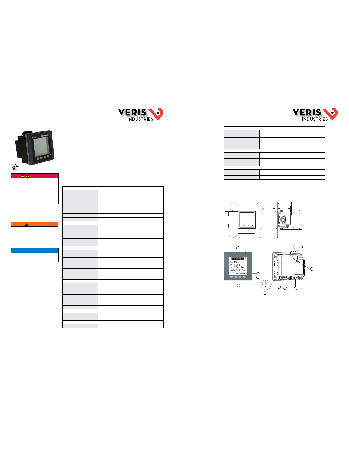
Product Overview
The E61C20 panel mount power and energy meter provides basic four quadrant me tering capability with
Modbus communication via ethernet cab le. It includes voltage and current inputs, optically is olated digital
inputs and outputs, and a multi-tar iff feature for accumulated energy readings. The E61C20 requires exter nal
power to operate.
E61C20
Power and Energy Meter
Specifications
CONTROL POWER
AC 100-277 VAC
L-N
± 10%; 100-415 VAC
L-L
± 10%
DC 125-250 VDC ± 20%
AC Burden 5 W/11 VA max. at 415 VAC
DC Burden 4 W max. at 125 VDC
Frequency 50/60 Hz ± 5 Hz
Fuses 500 mA
Wire Size 0.82 - 3.31 mm
2
(18 - 12 AWG)
Terminal Block Torque 0.5 - 0.6 N·m (4.4 - 5.3 in·lb)
VOLTAGE INPUTS
Measured Voltage UL CAT III, 20-347 V
L-N
/35-600V
L-L
(Delta)
IEC CAT III, 20- 400V
L-N
/35-690V
L-L
Frequency 50/60 Hz
Impedance 5 MΩ
Wire Size 0.82 - 3.31 mm
2
(18 - 12 AWG)
Terminal Block Torque 0.5 - 0.6 N·m (4.4 - 5.3 in·lb)
CURRENT INPUTS
Nominal Current 1 A or 5 A (Note: 1A accuracy i s from 150mA only)
Measured Current 5 mA to 8.5 A
Withstand 20 A continu ous; 50 A@10 sec/hr; 500 A@1 s ec/hr
Frequency 50/60 Hz
Impedance <0.3 mΩ
Burden <0.026 VA@8.5 A
Wire Size 0.82 - 3.31 mm
2
(18 - 12 AWG)
Terminal Block Torque 0.9 - 1.0 N·m (8.0 - 9.0 in·lb)
DIGITAL OUTPUT
Maximum Load Voltage 40 VDC
Maximum Load Current 20 mA
On Resistance 50 Ω max.
Pulse Width 50% duty cyc le
Pulse Frequency 25 Hz max.
Leakage Current 0.03 µA
Isolation 5 kV RMS
LED OPTICAL OUTPUT
Pulse Width (orange LED) 200 µsec
Pulse Frequency 50 Hz max.
COMMUNICATION
Ethernet Port 10/100 Mbps; Modbus T CP/IP; 1 port
Specifications (cont.)
MEASUREMEN T ACCURACY
Accuracy IEC 61557-12 PMD/[SD|SS]/K70/0.5
Real Power and Energy Class 0.5 as per IEC 61557-12; Class 0.5 S as per IEC 62053-22
Reactive Power and Energy Class 2 as per IEC 61557-12; Class 2S as per I EC 62053-23
Current, Phase Class 0.5 as pe r IEC 61557-12
Voltage , L-N Class 0 .5 as per IEC 61557-12
OPERATING CONDITIONS
Operating Temperature
and Humidity Range
-25°C to 70°C (-13° to 158°F) (5% to 95% RH noncond ensing)
(display functions to -25°C with reduced performance)
Storage Temperature Range -40° to 85°C (-40° to 185°F)
Altitude of Operation < 2000 m
COMPLIANCE INFORMATION
Approvals CE IEC 61010-1 Ed -3; UL6 1010-1; IEC 6 1010-1; IEC 62052-11;
IEC 61557-12
Housing Pollution Degree 2, Installation Category III
Not suitable for wet locations. For indoor use only.
ZL0142-0B Page 1 of 6 ©2014 Veris Industries USA 800.354.8556 or +1.503.598.4564 / support@veris.com 1214
Alta Labs, Enercept , Enspector, Hawk eye, Trustat, Aer ospond, Veris, a nd the Veris ‘V ’ logo are trad emarks or re gistered tra demarks of Ver is Industrie s, L.L.C. in th e USA and/or other co untries.
Other companies’ trademarks are hereby acknowledged to belong to their respective owners.
ZL0142-0B Page 2 of 6 ©2014 Veris Industries USA 800.354.8556 or +1.503.598.4564 / support@veris.com 1214
Alta Labs, Enercept , Enspector, Hawk eye, Trustat, Aer ospond, Veris, a nd the Veris ‘V ’ logo are trad emarks or re gistered tra demarks of Ver is Industrie s, L.L.C. in th e USA and/or other co untries.
Other companies’ trademarks are hereby acknowledged to belong to their respective owners.
Dimensions
3.8”
(96 mm)
3.8”
(96 mm)
4.2”
(108 mm)
3.6”
(91 mm)
0.5”
(13 mm)
3.1”
(79 mm)
2.8”
(72 mm)
Product Diagram
A. Menu selection buttons
B. LED indicators (orange and green)
Orange is programmable for either alarm or
energy pulse
Green indicates meter heartbeat/communications
C. Navigation or menu selections
▲ Exit screen and go up one level
▲ Move cursor up the list of options
▼ Move cursor down and display more options
▲ Move cursor one character to the left
▲ Scroll right and display more menu items
E F
GH
I
J
A
B
C
D
K
+ Show the next item in the list, or increase the highlighted value
– Show the previous item i n the list
D. Maintenance and alarm notification area
E. Voltage inputs
F. Control power
G. Current inputs
H. Status inputs/digital outputs
I. Ethernet communication port
J. Gasket
K. Latching points
Page 2
Installation Guide
Power Monitoring
E61C20
TM
Installation Guide
Power Monitoring
E61C20
TM
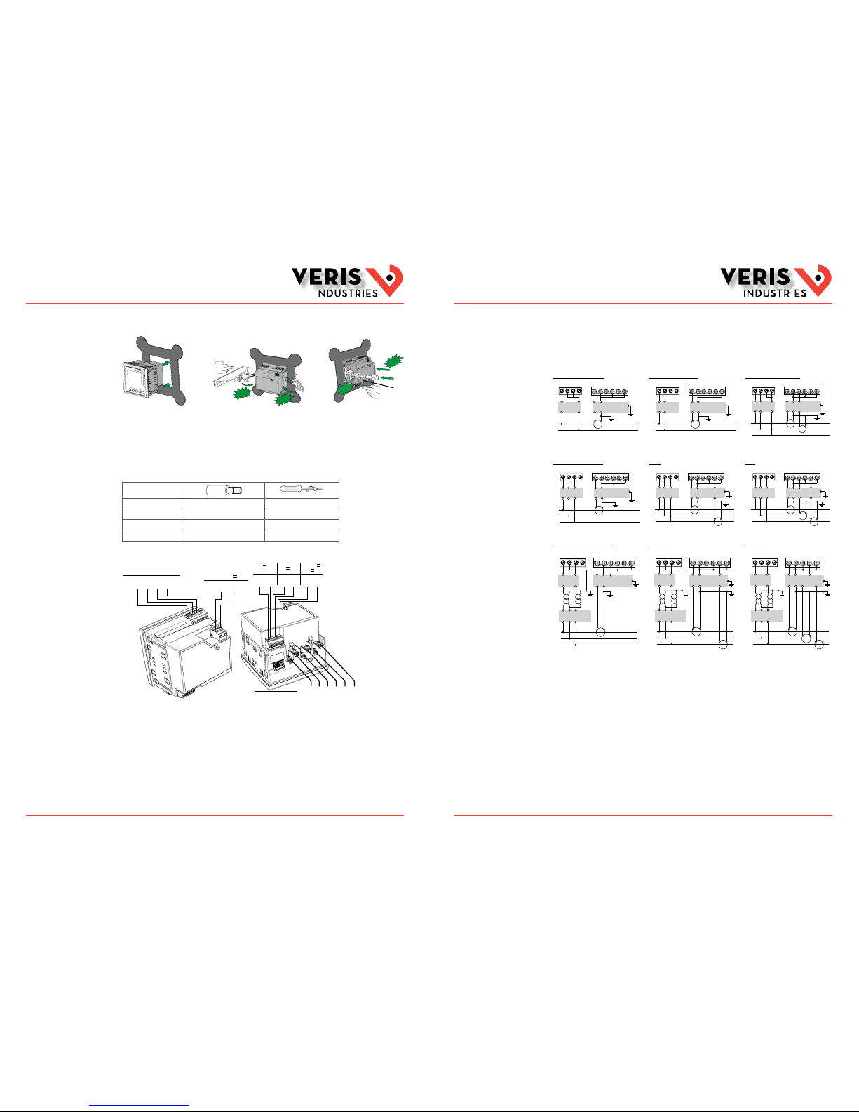
Installation
1. Disconnect power prior to the ins tallation. Use a properly rated voltage sensing device to ensure p ower is off.
2. Cut a mounting hole and install the E61 as shown.
CLICK
CLIC
K
CLAC
K
CLAC
K
3. Wire the meter (see the Wiring section).
4. Reconnect power to the meter.
5. Configure the meter (see the Configuration section).
Wiring
For all terminals, apply the correct torque.
Voltage Inputs 0.82 - 3.31 mm2 (18 - 12 AWG) 0.5 - 0.6 N·m (4.4 - 5.3 in·lb)
Control Power 0.82 - 3.31 mm
2
(18 - 12 AWG) 0.5 - 0.6 N·m (4.4 - 5.3 in·lb)
Status Input/Digital Output 0.33 - 2.08 mm
2
(22 - 14 AWG) 0.5 - 0.6 N·m (4.4 - 5.3 in·lb)
Current Inputs 0.82 - 3.31 mm
2
(18 - 12 AWG) 0.9 - 1.0 N·m (8.0 - 9.0 in·lb)
Voltage Inputs
UL CAT III, 20-347V
L-N
/35-600V
L-L
IEC CAT III, 20-400V
L-N
/35-690V
L-L
V1 V2 V3 V4
(1) (2) (3) (4)
L1 L2
(8) (9)
Control Power
100-277V
L-N
/415V
L-L
±10% ~
50/60 ± 5 Hz < 11 VA
125-250V ± 20% < 4W
Status Input/Digital Output
40V max.
20mA max.
36V max.
24V
8mA max.
D1+ D2+
(60) (62)
S1+ S2+
(40) (42)
−/C +
(57) (56)
Current Inputs
1A/5A nom., 0.0005-5(6)A
(10) (11) (12) (13) (14) (15)
I1+ I1- I2+ I2- I3+ I
3-
Modbus TCP/IP
(30)
Act Link
10/100
The ground terminal is not available on the meter. Connect shield to ground at t he other end.
Control power terminals (L1 and L2) are not polarity sensitive. If using an AC power supply with neutral, connec t the neutral
to the meter’s L2 terminal. Always use a fuse on L1. Fuse L2 when connecting an ungrounde d neutral to the control power.
If using a control power transformer, fuse both the pr imary and the secondary sides of the tran sformer. Use fuses/circuit
breakers that are rated for the installation voltag e and sized for the available fault current.
Use shielded ethernet cable. There is no ground ter minal on the meter, so connect shield to ground at the other end of the
cable. Install the meter in a location that minimizes t he overall ethernet cable rounting length.
ZL0142-0B Page 3 of 6 ©2014 Veris Industries USA 800.354.8556 or +1.503.598.4564 / support@veris.com 1214
Alta Labs, Enercept , Enspector, Hawk eye, Trustat, Aer ospond, Veris, a nd the Veris ‘V ’ logo are trad emarks or re gistered tra demarks of Ver is Industrie s, L.L.C. in th e USA and/or other co untries.
Other companies’ trademarks are hereby acknowledged to belong to their respective owners.
ZL0142-0B Page 4 of 6 ©2014 Veris Industries USA 800.354.8556 or +1.503.598.4564 / support@veris.com 1214
Alta Labs, Enercept , Enspector, Hawk eye, Trustat, Aer ospond, Veris, a nd the Veris ‘V ’ logo are trad emarks or re gistered tra demarks of Ver is Industrie s, L.L.C. in th e USA and/or other co untries.
Other companies’ trademarks are hereby acknowledged to belong to their respective owners.
CT Wiring
Clearly label the device’s disconnect circuit mec hanism and install it within easy reach of the operator. Use fuses/circuit
breakers that are rated for the installation voltag e and sized for the available fault current. A fuse for neu tral is required if the
source neutral is not grounded.
1 Phase
1 Phase, 2 Wire, L-N 1 Phase, 2 Wire, L-L 1 Phase, 3 Wire, L-L-N
Shorting
Block
Fuses and
Disconnect
V1 V2 V3 Vn
(I1) (I3)(I2)
+
L
N
+ - + - + -
Shorting
Block
Fuses and
Disconnect
V1 V2 V3 Vn
(I1) (I3)(I2)
+
L1
L2
+ - + - + -
Shorting
Block
Fuses and
Disconnect
V1 V2 V3 Vn
(I1) (I3)(I2)
+
+
L1
L2
N
+ - + - + -
3 Phase, 3 Wire
1 CT, Balanced Load 2 CT 3 CT
Shorting
Block
Fuses and
Disconnect
V1 V2 V3 Vn
(I1) (I3)(I2)
+
L1
L2
L3
+ - + - + -
Shorting
Block
Fuses and
Disconnect
V1 V2 V3 Vn
(I1) (I3)(I2)
+
+
L1
L2
L3
+ - + - + -
Shorting
Block
Fuses and
Disconnect
V1 V2 V3 Vn
(I1) (I3)(I2)
+
+
+
L1
L2
L3
+ - + - + -
1 CT, 2 PT, Balanced Load 2 CT, 2 PT 3 CT, 2 PT
Fuses and
Disconnect
Shorting
Block
PT Primary Fuses and
Disconnect Switch
V1 V2 V3 Vn
(I1) (I3)(I2)
+
L1
L2
L3
+ - + - + -
Fuses and
Disconnect
Shorting
Block
PT Primary Fuses and
Disconnect Switch
V1 V2 V3 Vn
(I1) (I3)(I2)
+
+
L1
L2
L3
+ - + - + -
Fuses and
Disconnect
Shorting
Block
PT Primary Fuses and
Disconnect Switch
V1 V2 V3 Vn
(I1) (I3)(I2)
+
+
+
L1
L2
L3
+ - - + -
Wiring (cont.)
Page 3

Installation Guide
Power Monitoring
E61C20
TM
Installation Guide
Power Monitoring
E61C20
TM
ZL0142-0B Page 5 of 6 ©2014 Veris Industries USA 800.354.8556 or +1.503.598.4564 / support@veris.com 1214
Alta Labs, Enercept , Enspector, Hawk eye, Trustat, Aer ospond, Veris, a nd the Veris ‘V ’ logo are trad emarks or re gistered tra demarks of Ver is Industrie s, L.L.C. in th e USA and/or other co untries.
Other companies’ trademarks are hereby acknowledged to belong to their respective owners.
ZL0142-0B Page 6 of 6 ©2014 Veris Industries USA 800.354.8556 or +1.503.598.4564 / support@veris.com 1214
Alta Labs, Enercept , Enspector, Hawk eye, Trustat, Aer ospond, Veris, a nd the Veris ‘V ’ logo are trad emarks or re gistered tra demarks of Ver is Industrie s, L.L.C. in th e USA and/or other co untries.
Other companies’ trademarks are hereby acknowledged to belong to their respective owners.
Wiring (cont.)
3 Phase, 4 Wire
1 CT, Balanced Load 2 CT, Balanced Load 3 CT
Shorting
Block
Fuses and
Disconnect
V1 V2 V3 Vn
(I1) (I3)(I2)
+
L1
L2
L3
N
+ - + - + -
Shorting
Block
Fuses and
Disconnect
V1 V2 V3 Vn
(I1) (I3)(I2)
+
+
L1
L2
L3
N
+ - + - + -
Shorting
Block
Fuses and
Disconnect
V1 V2 V3 Vn
(I1) (I3)(I2)
+
+
+
L1
L2
L3
N
+ - + - + -
1 CT, 3 PT, Balanced Load 2 CT, 3 PT, Balanced Load 3 CT, 3 PT
PT Primary Fuses and
Disconnect Switch
Fuses and
Disconnect
Shorting
Block
V1 V2 V3 Vn
(I1) (I3)(I2)
+
L1
L2
L3
N
+ - + - + -
PT Primary Fuses and
Disconnect Switch
Fuses and
Disconnect
Shorting
Block
V1 V2 V3 Vn
(I1) (I3)(I2)
+
+
L1
L2
L3
N
+ - + - + -
PT Primary Fuses and
Disconnect Switch
Fuses and
Disconnect
Shorting
Block
V1 V2 V3 Vn
(I1) (I3)(I2)
+
+
+
L1
L2
L3
N
+ - + - + -
Configuration
Notification Icons
Notification icons appear in the upper lef t corner of the display screen. If no icon appears, the meter is f unctioning normally.
Icon Description
The wrench icon indicates that the power meter requires maintenance.
The alarm icon indicates an alarm condition has occurred.
●
The blinking heartbeat icon indicates that the power meter is in normal operating condition.
For full details, see the E61C20 Configuration Guide, available at www.veris.com.
Digital Outputs
The meter is equipped with two digit al output ports (D1, D2) for use in the following applications:
• Switching applications (e.g., to provide on/off control signals for swi tching capacitor banks, generators, and other
external devices and equipment)
• Demand synchroniz ation applications, where the meter provides pulse signals to t he input of another meter to
control its demand period
• Energy pulsing applications, where a receiving device determines energy usage by counting the k_h pulses (k _h
= kWh, kVARh or kVAh depending on the energy parameter selected) coming f rom the meter’s digital output port
The digital outputs can handle voltage s less than 40 VDC. For higher voltage applications, use an e xternal relay in the
switching circuit.
Status Inputs
The meter is equipped with two stat us input ports (S1 and S2) for use in status monitoring applications .
The meter’s status inputs require an ex ternal voltage source to detect the stat us input’s on/off state. The meter detects an ON
state if the external voltage appear ing at the status input is within its operating r ange.
The external voltage can be derive d from either the whetting output prov ided by the meter or by a voltage source up to 36
VDC external to the meter.
Basic Menu Configuration
Maint
Reset
Meter
I
U-V PQS PF
F
Clock
E
Unbal
MnMx
Alarm
I/O
Timer
Setup
Diag
Comm Alarm I/O HMI
Clock
Password = 0000
(default)
THD Harm
Basic
For the full menu with explanations of all options, s ee the E61C20 Configuration Guide, available at www.veris.com.
Multi-Tariff Overview
The meter’s multi-tariff feature includes up to 4 di fferent tariffs to store accumulated energy data. Th e tariff modes are
defined below.
Command Mode Send a Modbus command to the device that sets the active tariff. This tariff is applied to the measured
energy until another Modbus command sets a different tariff.
Time of Day Mode Create a tariff schedule that specifies where the meter stores energy or input metered data, based on
the time of year (month, day), the type of day (every day, weekend, weekday or a specific day of the
week), or time of day.
Input Mode The meter’s digital inputs set which tariff is applied to the energy that is presently being consumed. If a
digital input is used for multi-tariff, it cannot be used for an exclusive association (such as Demand Sync
or Input Metering), but digital inputs can be shared with a non-exclusive association (such as Alarms).
 Loading...