

Page 1
Installation Guide
the FCC Rules. These limits are designed to provide reasonable protection
residential environment. This equipment generates, uses, and can radiate
Power Monitoring
E51H2, E51H5
Bi-Directional Compact
Power and Energy Meter
With BACnet MS/TP Support
Product Overview
n
C
e
A
t
B
·
®
·
T
S
E
E
S
I
T
R
I
O
N
T
G
A
L
R
A
O
RoHS
Compliant
B
E51H5 o nly
DANGER
HAZARD OF ELECTRIC SHOCK, EXPLOSION, OR ARC FLASH
• Follow safe electrical work practices. See NFPA 70E in the USA, or applicable local codes.
• This equipment must only be installed and serviced by qualified electrical personnel.
• Read, understand and follow the instructions before installing this product.
• Turn off all power supplying equipment before working on or inside the equipment.
• Any covers that may be displaced during the installation must be reinstalled
before powering the unit.
• Use a properly rated voltage sensing device to confirm power is off.
DO NOT DEPEND ON THIS PRODUCT FOR VOLTAGE INDICATION
Failure to follow these instructions will result in death or serious injury.
A qualied person is one who has skills and knowledge related to the construction and
operation of this electrical equipment and the installation, and has received safety
training to recognize and avoid the hazards involved. NEC2009 Article 100
No responsibility is assumed by Veris Industries for any consequences arising out of the
use of this material.
Control system design must consider the potential failure modes of control paths and, for
certain critical control functions, provide a means to acheive a safe state during and after a
path failure. Examples of critical control functions are emergency stop and over-travel stop.
WARNING
LOSS OF CONTROL
∙ Assure that the system will reach a safe state during and after a control path failure.
∙ Separate or redundant control paths must be provided for critical control func tions.
∙ Test the eect of transmission delays or failures of communication links.
∙ Each implementation of equipment using communication links must be individually
and thoroughly tested for proper operation before placing it in service.
Failure to follow these instructions may cause injury, death or equipment damage.
1
For additional information about anticipated transmission delays or failures of the link, refer to
NEMA ICS 1.1 (latest edition). Safety Guidelins for the Application, Installation, and Maintenance
of Solid-State Control or its equivalent in your specic country, language, and/or location.
NOTICE
• This product is not intended for life or safety applications.
• Do not install this product in hazardous or classified locations.
• The installer is responsible for conformance to all applicable codes.
• Mount this product inside a suitable fire and electrical enclosure.
FCC PART 15 INFORMATION
NOTE: This equipment has been tested by the manufacturer and found to
comply with the limits for a class B digital device, pursuant to part 15 of
against harmful interference when the equipment is operated in a
radio frequency energy and, if not installed and used in accordance with
the instruction manual, may cause harmful interference to radio
communications. This device complies with part 15 of the FCC Rules.
Operation is subject to the following two conditions:
(1) This device may not cause harmful interference, and
(2) this device must accept any interference received, including
interference that may cause undesired operation.
Modifications to this product without the express authorization of the
manufacturer nullify this statement.
For use in a P ollution D egree 2 or be tter envi ronment on ly. A Pollutio n Degree 2
environment must control conductive pollution and the possibility of condensation or
high hum idity. Cons ider the enc losure, th e correc t use of venti lation, the rmal prop erties
of the equ ipment, an d the relati onship wi th the envir onment. In stallati on categor y:
CAT II or CAT III. P rovide a di sconnec t device to di sconnec t the meter f rom the sup ply
source. P lace this de vice in clos e proximit y to the equ ipment and w ithin eas y reach of
the oper ator, and mark i t as the disc onnecti ng device. T he disconn ecting de vice shall
meet th e relevant r equireme nts of IEC 60 947-1 and IEC 60947-3 and sh all be suit able for
the appl ication. I n the US and Can ada, discon nectin g fuse hold ers can be us ed. Provi de
overcu rrent prot ection a nd discone cting dev ice for sup ply conduc tors wit h approved
current limiting devices suitable for protecting the wiring. If the equipment is used in a
manner n ot specie d by the manu facture r, the protec tion prov ided by the d evice may
be impaired.
ZL0109-0C Page 1 of 32 ©2013 Veris Industries USA 800.354.8556 or +1.503.598.4564 / support@veris.com 10131
Alta Labs, E nercept, Ensp ector, Hawkeye, Trus tat, Aerospo nd, Veris, and th e Veris ‘V’ log o are tradema rks or registe red tradema rks of Veris Ind ustries, L. L.C. in the USA and /or other countri es.
1
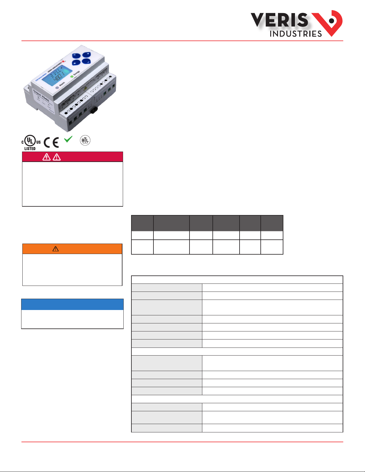
The E51H2 and E51H5 DIN rail power meters provide a solution for measuring energy data with a single device.
Inputs include control power, CT, and 3-phase voltage. Both models support BACnet MS/TP protocol. The E51H2
has one pulse contact input and a phase loss alarm output. The E51H5 has data logging capability and two pulse
contact inputs. The LCD screen on the faceplate allows instant output viewing.
The E51 meters are capable of bidirectional metering. Power is monitored in both directions (upstream and
downstream from the meter). The meter is housed in a plastic enclosure suitable for installation on T35 DIN rail
according to EN50022. The E51 can be mounted either on a DIN rail or in a panel. Observe correct CT orientation
when installing the device.
Product Identification
Model
E51H2
E51H5
BACnet MS/TP
Protocol Output
n n n n
n n n
Alarm
Output
Full Data
Set
Data
Logging
Pulse
Input
n
(2 pulses)
Specifications
MEASUREMENT ACCURACY
Real Power and Energy
Reactive Power and Energy
Current
Voltag e
Sample Rate
Data Update Rate
Type of Measurement
Measured AC Voltage
Metering Over-Range
Impedance
Frequency Range
CT Scaling
Measurement Input Range
Impedance
Other companies’ trademarks are hereby acknowledged to belong to their respective owners.
IEC 620 53 -22 Class 0.2S, A NSI C12.20 0.2%
IEC 620 53 -23 Class 2, 2%
0.2% (+ 0.0 05% per ° C deviation from 25°C ) from 1% to 5% of range;
0.1% (+0.0 05% per °C deviation from 25°C ) from 5% to 100 % of range
0.1% (+0.0 05% per °C deviation from 25°C ) from 90 VAC
2520 samples per second; no blind time
1 sec.
True RMS; one to three phase AC system
INPUT VO LTAG E CHARACTE RISTIC S
Minimum 90 V
UL Maximums: 600 V
(156 V
L-N
) for stated accuracy;
L-L
(3 47 V
L-L
); CE Maximum: 3 00 V
L-N
+20%
2.5 MΩ
/5 M Ω
L-N
L-L
45 to 65 Hz
INPUT CUR RENT CHARACTER ISTICS
Primar y: Adjustable from 5 A to 3 2,00 0 A
0 to 0.333 VAC or 0 to 1.0 VAC (+20 % over-range), rated for use with
Class 1 voltage inputs
10.6 kΩ (1/3 V mode) or 32.1 kΩ (1 V mode)
to 600 VAC
L-N
L-N
TM
L-L
Page 2

Installation Guide
Power Monitoring
EH, EH
TM
Specifications (cont.)
CONTROL POWER
AC
5 VA max.; 9 0V min.;
DC*
Ride Through Time
Pulse
Minimum Pulse Width
Alarm Contacts (E51H2 only)
RS-485 Port
Weight
IP Degree of Protec tion
(IEC 6 0529)
Display Characteristics
Terminal Block Screw Torque
Terminal Block W ire Size
Rail
Operating Temperature Range
Storage Temperature Range
Humidity Range
Altitude of Operation
US and Canada
CE
Dielectric Withstand
Conducted and Radiated
Emissions
Conducted and Radiated
Immunity
US and Canada (cULus)
Europe (CE)
UL Maximums: 600 V
3 W max.; U L and CE: 125 to 300 VDC
100 msec at 120 VAC
INP UT
Solid -state or mechanical contacts (current less than 1 mA)
E51H2: 1 pulse input; E51H5: 2 pulse inputs
20 msec
OUTPUT
N.C., static output ( 30VAC/ DC, 100 mA max. @ 25°C,
derate 0.56mA per °C above 25°C)
2-wire, 9 60 0 to 115.2 kbaud, BACnet MS/TP
MECHAN ICAL CHARACTER ISTICS
0.62 lb ( 0.28 kg)
IP40 front display; IP20 Meter
Back-lit blue LCD
0.37 to 0.44 ft-lb ( 0.5 to 0.6 N·m)
24 to 14 AWG (0.2 to 2.1 mm2)
T35 ( 35mm) DIN Rail per EN50022
OPERATING CO NDITION S
-30° to 70°C (-22° to 158° F)
-4 0° to 85°C (-40° to 185°F)
<95% RH noncondensing
3000 m
COMPLIANCE INFORMATION
CAT III, Pollution degree 2;
for distribution systems up to 347V
CAT III, Pollution degree 2;
for distribution systems up to 300 V
Per UL 50 8, EN61010
FCC par t 15 Class B, EN55011/EN6100 0 Class B ( residential and light
industrial)
EN61000 Class A (heavy industrial)
UL508 (open type device) /CSA 22. 2 No. 14- 05
EN6 1010-1
(3 47 V
L-L
* External DC current limiting is required, see fuse recommendations.
); CE Maximum: 3 00 V
L-N
/600VAC
L-N
L-N
L-L
L-N
ZL0109-0C Page 2 of 32 ©2013 Veris Industries USA 800.354.8556 or +1.503.598.4564 / support@veris.com 10131
Alta Labs, E nercept, Ensp ector, Hawkeye, Trus tat, Aerospo nd, Veris, and th e Veris ‘V’ log o are tradema rks or registe red tradema rks of Veris Ind ustries, L. L.C. in the USA and /or other countri es.
Other companies’ trademarks are hereby acknowledged to belong to their respective owners.
Page 3

Installation Guide
Power Monitoring
EH, EH
TM
Table of Contents
Dimensions 4
Application Example 4
Data Outputs 5
Product Diagram 5
Display Screen Diagram 6
Installation 7
Supported System Types 8
Wiring Symbols 8
Wiring Diagrams 9
Control Power Diagrams 10
Quick Setup Instructions 11
Pulse Contact Inputs 12
User Interface Menu Abbreviations Dened 12
User Interface for Data Conguration 13
Alert/Reset Information 15
User Interface for Setup 16
RS-485 Communications 18
BACnet Default Settings 19
BACnet Programming Information 20
Legend 22
Device Objects 22
Analog_Value Objects 23
Analog_Input Objects 25
Binary_Input Objects 29
Data Logging (E51H5 Only) 30
Trend_Log Objects 31
Troubleshooting 32
China RoHS Compliance Information (EFUP Table) 32
ZL0109-0C Page 3 of 32 ©2013 Veris Industries USA 800.354.8556 or +1.503.598.4564 / support@veris.com 10131
Alta Labs, E nercept, Ensp ector, Hawkeye, Trus tat, Aerospo nd, Veris, and th e Veris ‘V’ log o are tradema rks or registe red tradema rks of Veris Ind ustries, L. L.C. in the USA and /or other countri es.
Other companies’ trademarks are hereby acknowledged to belong to their respective owners.
Page 4
Installation Guide
Power Monitoring
EH, EH
TM
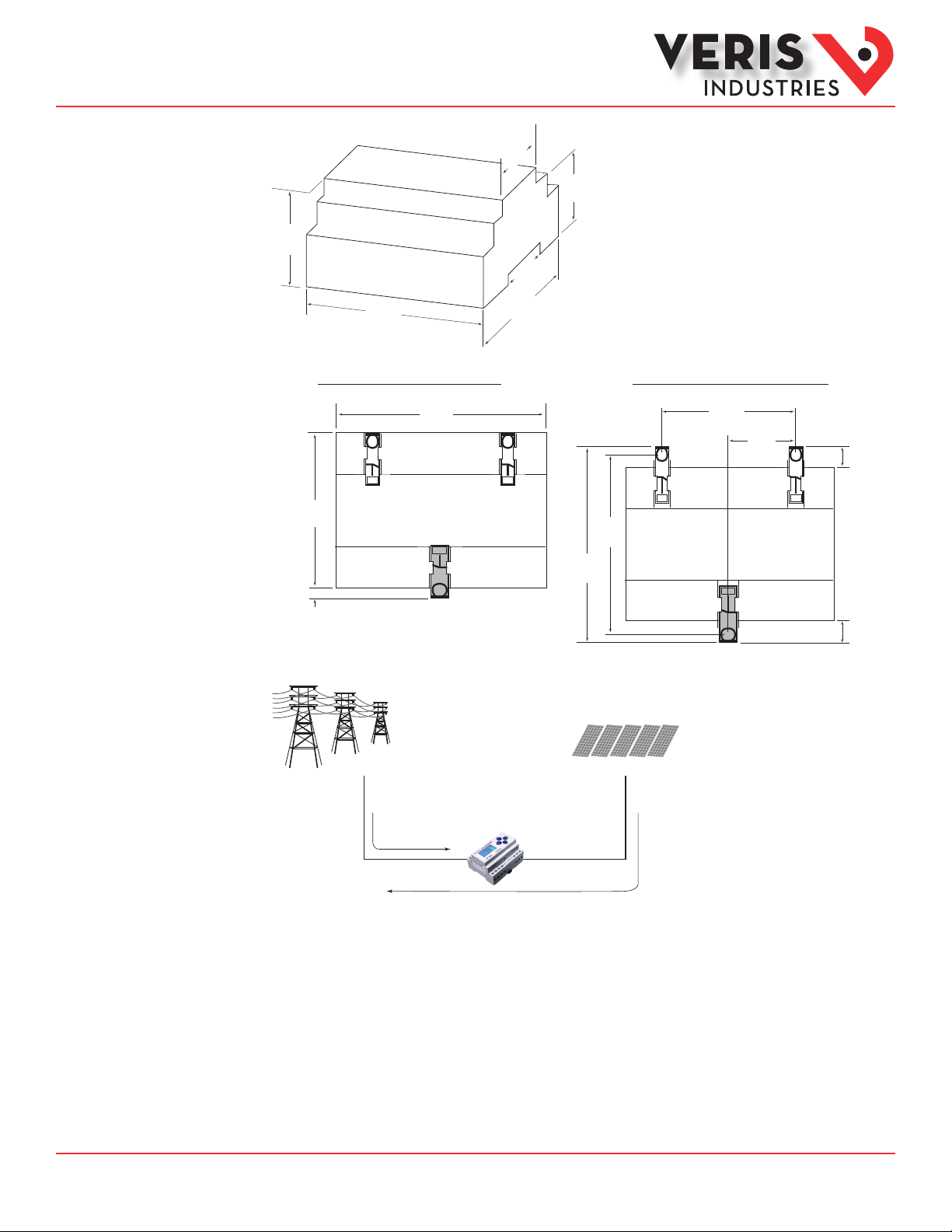
Dimensions
1.8”
(45mm)
1.9”
(48mm)
2.3”
(59mm)
1.5”
(39mm)
4.2”
(107mm)
3.6”
(91mm)
Bottom View (DIN Mount Option) Bottom View (Screw Mount Option)
2.4 “
(61 mm)
+
0.2 “
(4 mm)
3.6 “
(91 mm)
4.2 “
(107 mm)
3.9“
(99 mm)
4.3 “
(109 mm)
1.2 “
(31 mm)
++
0.3 “
(8 mm)
0.4 “
(10 mm)
Application Example
Main Utility Grid Solar Panels
Imported Power
Exported Power
ZL0109-0C Page 4 of 32 ©2013 Veris Industries USA 800.354.8556 or +1.503.598.4564 / support@veris.com 10131
Alta Labs, E nercept, Ensp ector, Hawkeye, Trus tat, Aerospo nd, Veris, and th e Veris ‘V’ log o are tradema rks or registe red tradema rks of Veris Ind ustries, L. L.C. in the USA and /or other countri es.
Other companies’ trademarks are hereby acknowledged to belong to their respective owners.
Page 5
Installation Guide
Power Monitoring
EH, EH
TM
Data Outputs
Full Data Set (FDS):
Power (kW)
Energy (kWh)
Congurable for CT & PT ratios, system type, and passwords
Diagnostic alerts
Current: 3-phase average
Volts: 3-phase average
Current: by phase
Volts: by phase Line-Line and Line-Neutral
Power: Real, Reactive, and Apparent 3-phase total and per phase
Power Factor: 3-phase average and per phase
Frequency
Power Demand: Most Recent and Peak
Demand Conguration: Fixed, Rolling Block, and External Sync
Real Time Clock: uses BACnet Time Synchronization services
Data Logging (E51H5 only; includes all FDS outputs, plus):
3 BACnet Log_Events: each buer holds 5760 time-stamped 32-bit entries
(User congures which 3 data points are stored in these buers)
User congurable logging interval
(When congured for a 15 minute interval, each buer holds 60 days of data)
Continuous and Single Shot logging modes: user selectable
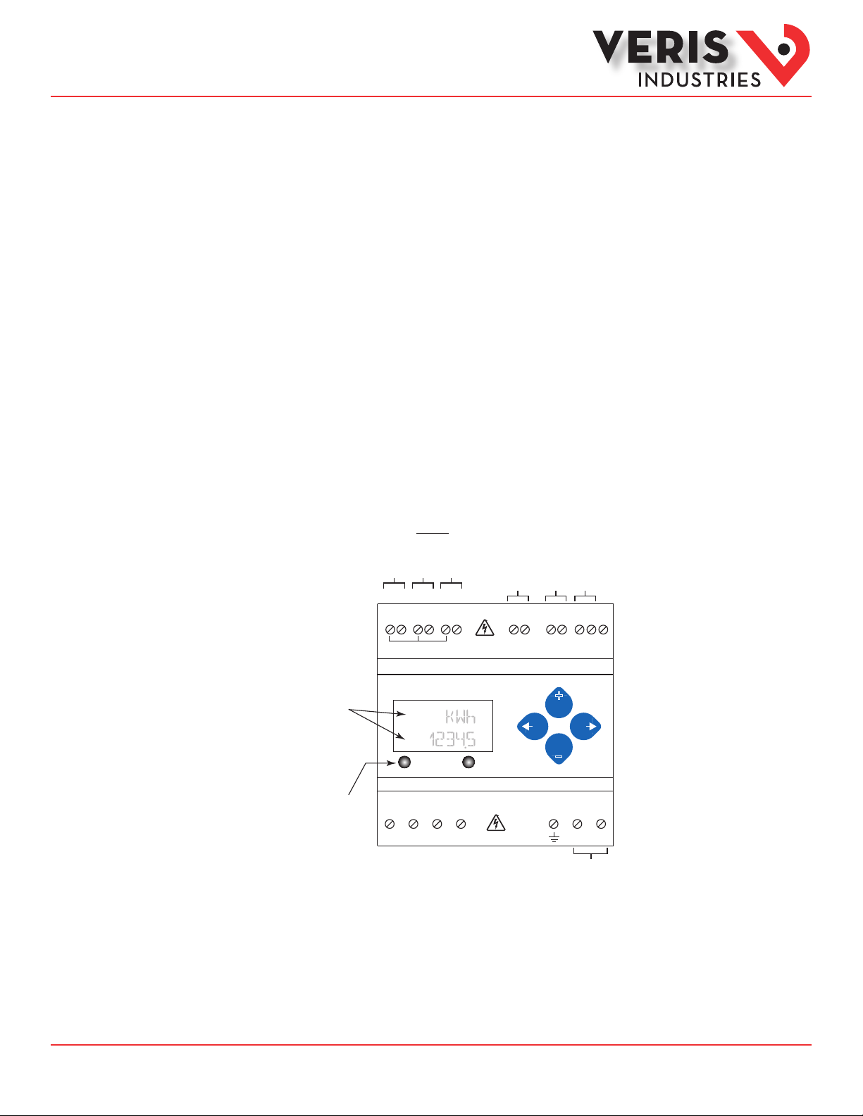
Product Diagram
Two 5-character rows
of display text.
Top row alphanumeric;
Bottom row numeric only
The red Alarm LED lights
when any of the 3 phase
voltages drop below the
selected threshold.
The green Energy LED is not
used on the E5xH2A.
E51H2
IA
IB
IC
X2 X1 X2 X1 X2 X1
(X2) A (X1) (X2) B (X1) (X2) C (X1)
CT Inputs
1 or 0.333 VAC
Alarm Energy
VOLTAGE INPUTS
CAT III 50/60 Hz
A B C N 1 2
VA
UL: 90V
L-N
VB
VC
Neutral
- 600V
CE: 90V
L-L
Phase Loss
L-N
Alarm Output
- 300V
L-N
Pulse Input
+ - S
+
–
CONTROL POWER
0.1A 50/60 Hz
Earth
RS-485
BACnet
Control
Shield
Power
ZL0109-0C Page 5 of 32 ©2013 Veris Industries USA 800.354.8556 or +1.503.598.4564 / support@veris.com 10131
Alta Labs, E nercept, Ensp ector, Hawkeye, Trus tat, Aerospo nd, Veris, and th e Veris ‘V’ log o are tradema rks or registe red tradema rks of Veris Ind ustries, L. L.C. in the USA and /or other countri es.
Other companies’ trademarks are hereby acknowledged to belong to their respective owners.
Page 6
Installation Guide
Power Monitoring
EH, EH
TM
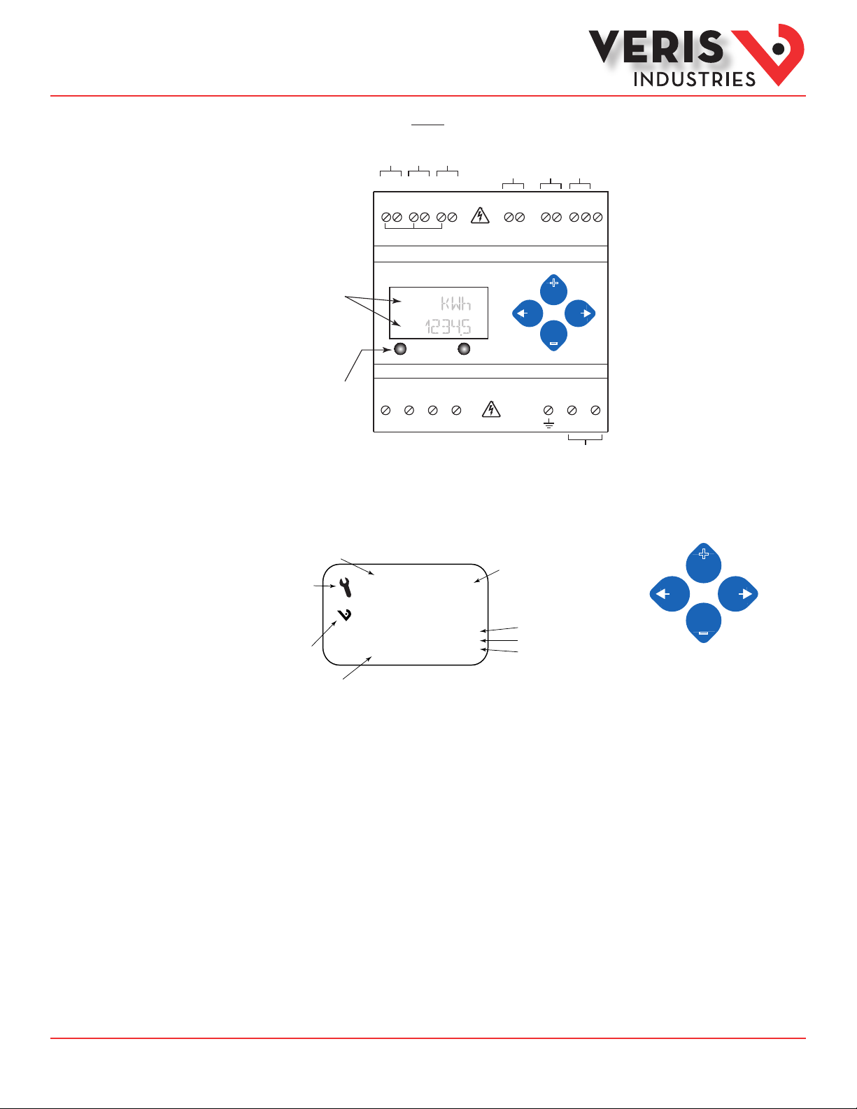
Product Diagram
(cont.)
Display Screen
Diagram
E51H5
IA
IB
IC
X2 X1 X2 X1 X2 X1
(X2) A (X1) (X2) B (X1) (X2) C (X1)
CT Inputs
1 or 0.333 VAC
Two 5-character rows
of display text.
Top row alphanumeric;
Bottom row numeric only
Alarm Energy
The red Alarm LED lights
when any of the 3 phase
voltages drop below the
VOLTAGE INPUTS
CAT III 50/60 Hz
UL: 90V
L-N
- 600V
selected threshold.
The green Energy LED lights
when the pulse 1 input
contacts are active or closed.
A B C N 1 2
VA
VB
VC
Neutral
LCD Screen: Buttons:
Screen Name or Units
Diagnostic Alert:
indicates that one or
more of the alarm
bits (Binary_Objects
1-15) are active.
Logo
Numeric Data
♥
Tx
Rx
ERR
Pulse Input 1
Pulse Inputs
1 2 + - S
CE: 90V
- 300V
L-L
L-N
L-N
Alive Indicator
RS-485 Equipped Units Only:
Transmit Data
Receive Data
Receive Data Error
Pulse Input 2
RS-485
+
–
CONTROL POWER
0.1A 50/60 Hz
Earth
BACnet
Shield
Control
Power
(Left)
Back
(Up)
Select
+
(Right)
Next
–
(Down)
Select
ZL0109-0C Page 6 of 32 ©2013 Veris Industries USA 800.354.8556 or +1.503.598.4564 / support@veris.com 10131
Alta Labs, E nercept, Ensp ector, Hawkeye, Trus tat, Aerospo nd, Veris, and th e Veris ‘V’ log o are tradema rks or registe red tradema rks of Veris Ind ustries, L. L.C. in the USA and /or other countri es.
Other companies’ trademarks are hereby acknowledged to belong to their respective owners.
Page 7
Installation Guide
Power Monitoring
EH, EH
TM
Installation
Disconnect power prior to installation.
Reinstall any covers that are displaced during the installation before powering the unit.
Mount the meter in an appropriate electrical enclosure near equipment to be monitored.
Do not install on the load side of a Variable Frequency Drive (VFD), aka Variable Speed Drive (VSD)
or Adjustable Frequency Drive (AFD).
Observe correct CT orientation.
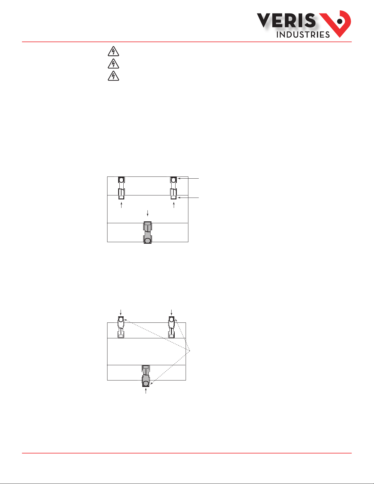
The meter can be mounted in two ways: on standard 35 mm DIN rail or screw-mounted to the interior surface of the enclosure.
A. DIN Rail Mounting
1. Attach the mounting clips to the underside of the housing by sliding them into the slots from the inside. The stopping pegs
must face the housing, and the outside edge of the clip must be ush with the outside edge of the housing.
2. Snap the clips onto the DIN rail. See the diagram of the underside of the housing (below).
Clip flush with
outside edge
Snap onto
Insert clips from inside
DIN rail
3. To reduce horizontal shifting across the DIN rail, use two Veris AV02 end stop clips.
B. Screw Mounting
1. Attach the mounting clips to the underside of the housing by sliding them into the slots from the outside. The stopping pegs
must face the housing, and the screw hole must be exposed on the outside of the housing.
2. Use three #8 screws (not supplied) to mount the meter to the inside of the enclosure. See the diagram of the underside of the
housing (below).
Insert clips from outside
Screw holes
exposed for
mounting
ZL0109-0C Page 7 of 32 ©2013 Veris Industries USA 800.354.8556 or +1.503.598.4564 / support@veris.com 10131
Alta Labs, E nercept, Ensp ector, Hawkeye, Trus tat, Aerospo nd, Veris, and th e Veris ‘V’ log o are tradema rks or registe red tradema rks of Veris Ind ustries, L. L.C. in the USA and /or other countri es.
Other companies’ trademarks are hereby acknowledged to belong to their respective owners.
Page 8
Installation Guide
Power Monitoring
EH, EH
TM
Supported System
Types
Number
of wires
Single-Phase Wiring
2 1 A 2 A, N L- N 10 1L + 1n AN 1
2 1 A 2 A, B L- L 11 2L AB 2
3 2 A, B 3 A, B, N L-L with N 12 2L + 1n AB AN, BN AN-BN 3
Three-Phase Wiring
3 3 A, B, C 3 A, B, C Delta 31 3L AB, BC, CA AB-BC-CA 4
4 3 A, B, C 4 A, B, C, N Grounded
The E51Hx power meters have a number of dierent possible system wiring congurations (see Wiring Diagrams, page 5). To
congure the meter, set the System Type via the User Interface or by writing the Present_Value of AV2 with the System Type value
in the table below. The System Type tells the meter which of its current and voltage inputs are valid, which are to be ignored, and
if neutral is connected. Setting the correct System Type prevents unwanted energy accumulation on unused inputs, selects the
formula to calculate the Theoretical Maximum System Power, and determines which phase loss algorithm is to be used. The phase
loss algorithm is congured as a percent of the Line-to-Line System Voltage (except when in System Type 10) and also calculates
the expected Line to Neutral voltages for system types that have Neutral (12 & 40).
Values that are not valid in a particular System Type will display as “----” on the User Interface or as QNAN in the BACnet objects.
CTs Voltage Connections System Type Phase Loss Measurements Wiring
Diagram
Qty ID Qty ID Type BACnet object
AV2
40 3L + 1n AB, BC, CA AN, BN, CN AN-BN-CN &
Wye
User Interface:
SETUP>S SYS
VLL VLN Balance Diagram
number
5, 6
AB-BC-CA
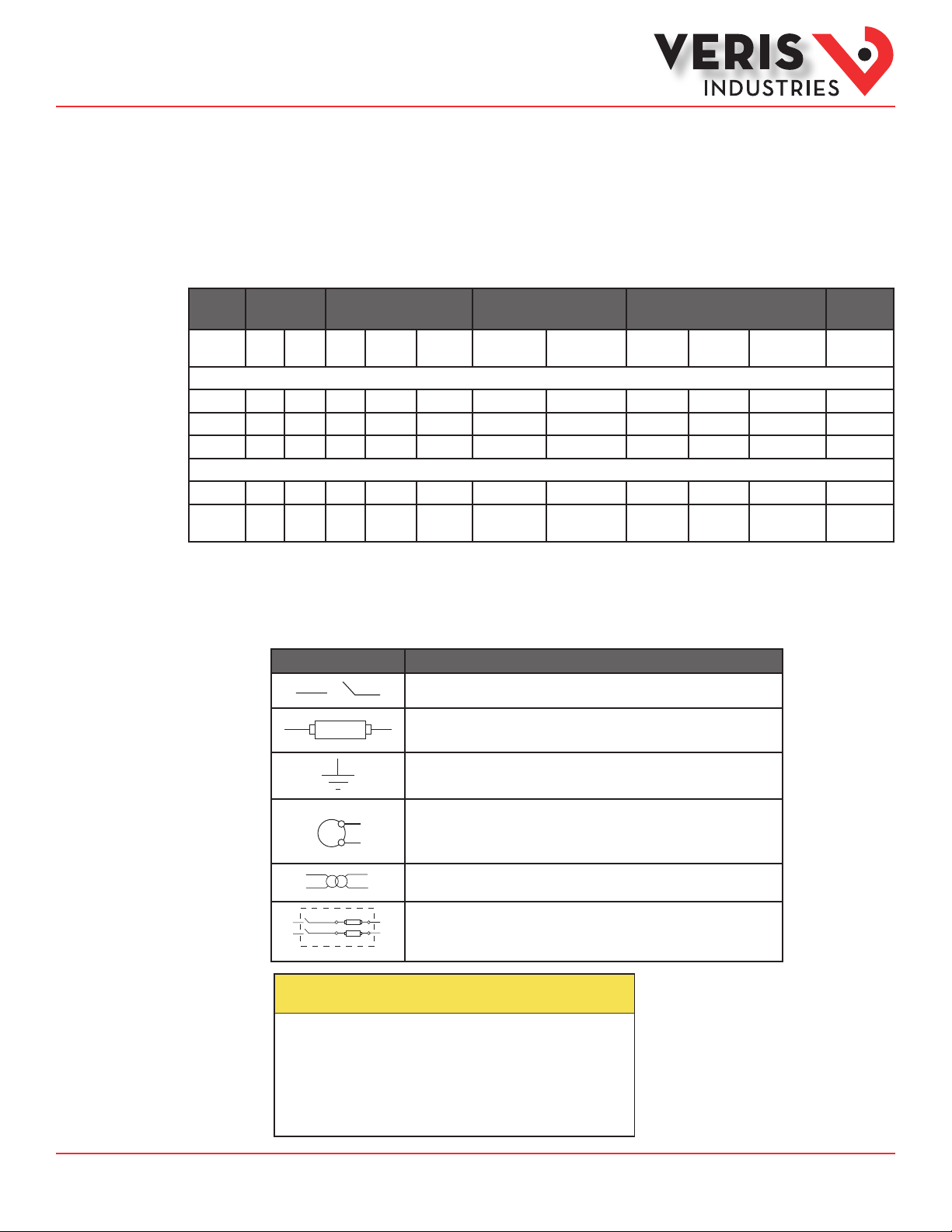
Wiring Symbols
To avoid distortion, use parallel wires for control power and voltage inputs.
The following symbols are used in the wiring diagrams on the following pages.
Symbol Description
Voltage Disconnect Switch
Fuse (installer is responsible for ensuring compliance with local requirements. No
fuses are included with the meter.)
Earth ground
X1
Current Transducer
Potential Transformer
Protection containing a voltage disconnect switch with a fuse or disconnect circuit
breaker. The protection device must be rated for the available short-circuit current at
the connection point.
CAUTION
RISK OF EQUIPMENT DAMAGE
• This product is designed only for use with 1V or 0.33V current
transducers (CTs).
• DO NOT USE CURRENT OUTPUT (e.g. 5A) CTs ON THIS PRODUCT.
• Failure to follow these instructions can result in overheating and
permanent equipment damage.
ZL0109-0C Page 8 of 32 ©2013 Veris Industries USA 800.354.8556 or +1.503.598.4564 / support@veris.com 10131
Alta Labs, E nercept, Ensp ector, Hawkeye, Trus tat, Aerospo nd, Veris, and th e Veris ‘V’ log o are tradema rks or registe red tradema rks of Veris Ind ustries, L. L.C. in the USA and /or other countri es.
Other companies’ trademarks are hereby acknowledged to belong to their respective owners.
Page 9
Installation Guide
Power Monitoring
EH, EH
TM
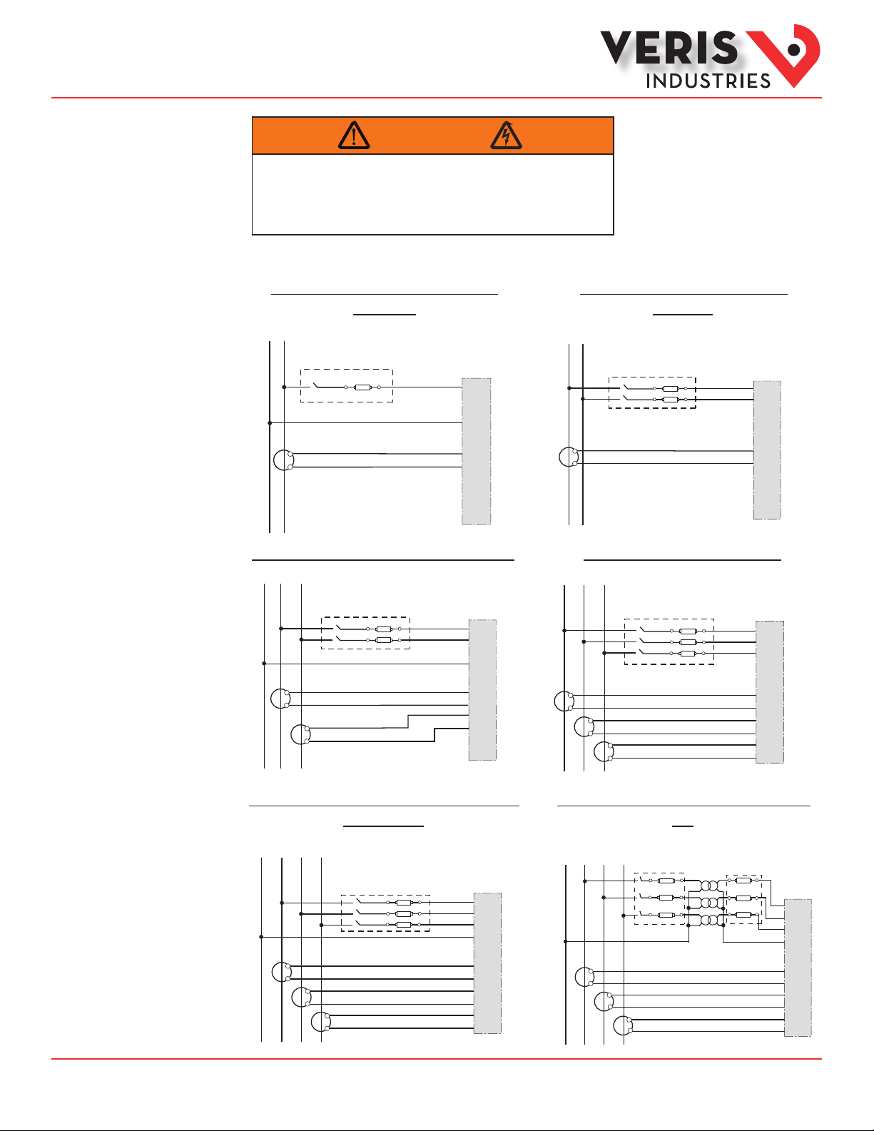
Wiring
WARNING
RISK OF ELECTRIC SHOCK OR PERMANENT EQUIPMENT DAMAGE
CT negative terminals are referenced to the meter’s neutral and may be at elevated voltages
· Do not contact meter terminals while the unit is connected
· Do not connect or short other circuits to the CT terminals
Failure to follow these instructions may cause injury, death or equipment damage.
Observe correct CT orientation.
Diagram 1: 1-Phase Line-to-Neutral 2- Wire
System 1 CT
N L1
Use System Type 10 (1L + 1n)
X1
X2
L1 L2
A
B
C
N
White
Black
X1
A
X2
X1
B
X2
X1
C
X2
X1
X2
Diagram 2: 1-Phase Line-to-Line 2-Wire
System 1 CT
Use System Type 11 (2L)
A
B
C
N
White
Black
X1
A
X2
X1
B
X2
X1
C
X2
Diagram 3: 1-Phase Direct Voltage Connection 2 CT
N
L1 L2
X1
X2
Use System Type 12 (2L + 1n) Use System Type 31 (3L)
A
B
C
N
White
Black
X1
X2
White
Black
X1
A
X2
X1
B
X2
X1
C
X2
Diagram 5: 3-Phase 4-Wire Wye Direct Voltage Input
Connection 3 CT
Use System Type 40 (3L + 1n)
L1N L2 L3
A
B
C
N
X1
X2
X1
X2
X1
X2
White
Black
White
Black
White
Black
X1
A
X2
X1
B
X2
X1
C
X2
Diagram 4: 3-Phase 3-Wire 3 CT no PT
L1 L2 L3
A
B
C
N
X1
X1
X2
X2
White
Black
White
X1
X2
Black
White
Black
X1
A
X2
X1
B
X2
X1
C
X2
Diagram 6: 3-Phase 4-Wire Wye Connection 3 CT
3 PT
Use System Type 40 (3L + 1n)
L1N L2 L3
A
B
C
N
X1
X1
X2
X2
X1
X2
White
Black
White
Black
White
Black
X1
X2
X1
X2
X1
X2
A
B
C
ZL0109-0C Page 9 of 32 ©2013 Veris Industries USA 800.354.8556 or +1.503.598.4564 / support@veris.com 10131
Alta Labs, E nercept, Ensp ector, Hawkeye, Trus tat, Aerospo nd, Veris, and th e Veris ‘V’ log o are tradema rks or registe red tradema rks of Veris Ind ustries, L. L.C. in the USA and /or other countri es.
Other companies’ trademarks are hereby acknowledged to belong to their respective owners.
Page 10
Installation Guide
Power Monitoring
EH, EH
TM
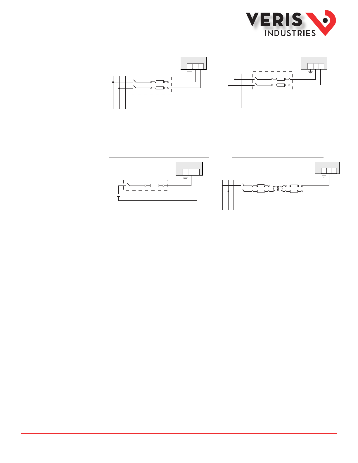
Control Power
Diagrams
Direct Connect Control Power (Line to Line)
L1
L2 L3
Line to Line from 90 VAC to 600 VAC (UL). In UL installations the
lines may be oating (such as a delta). If any lines are tied to an
earth (such as a corner grounded del ta), see the Line to Neutral
installation limits. In CE compliant installations, the lines must
be neutral (earth) referenced at less than 300 VAC
1 2G
L-N
Direct Connect Control Power (DC Control Power)
1 2G
DC Control Power from 125 VDC to 300 VDC
(UL and CE max.)
Direct Connect Control Power (Line to Neutral)
L1N L2 L3
Line to Neutral from 90 VAC to 347 VAC (UL) or 300 VAC (CE)
Control Power Transformer (CPT) Connection
L1N L2 L3
The Control Power Transformer may be wired L-N or L-L. Output to
meet meter input requirements
1 2G
1 2G
Fuse Recommendations
Keep the fuses close to the power source (obey local and national code requirements).
For selecting fuses and circuit breakers, use the following criteria:
• Select current interrupt capacity based on the installation category and fault current capability.
• Select over-current protection with a time delay.
• Select a voltage rating sucient for the input voltage applied.
• Provide overcurrent protection and disconnecting means to protect the wiring. For AC installations, use Veris AH02,
AH03, AH04, or equivalent. For DC installations, provide external circuit protection. Suggested: 0.5 A, time delay fuses.
• The earth connection (G) is required for electromagnetic compatibility (EMC) and is not a protective earth ground.
ZL0109-0C Page 10 of 32 ©2013 Veris Industries USA 800.354.8556 or +1.503.598.4564 / support@veris.com 10131
Alta Labs, E nercept, Ensp ector, Hawkeye, Trus tat, Aerospo nd, Veris, and th e Veris ‘V’ log o are tradema rks or registe red tradema rks of Veris Ind ustries, L. L.C. in the USA and /or other countri es.
Other companies’ trademarks are hereby acknowledged to belong to their respective owners.
Page 11

Installation Guide
Power Monitoring
EH, EH
TM
Quick Setup
Instructions
Use this section to enter:
- BACnet communication parameters
- CT (Current Transducer) output voltage and input current ranges
- The service type to be monitored
These instruc tions assume the meter is set to factory defaults. If it has been previously congured, check all optional values.
A. To Navigate to the Setup screens:
+
+
1. Press
or – repeatedly until SETU P screen appears.
2. Press to get to the PASWD screen.
+
3. Press to move through the digits. Use the
+
or – buttons to enter your password (the default is 00000).
4. Press to move to the rst Setup screen (S BAC)
+
+
5. Use
or – to select the parameter screen you want to set.
+
6. After you set the parameters you want, use
+
or – to select the next Setup screen or to exit the Setup screens (return to
SETU P).
B. To Enter BACnet communication parameters
1. Navigate to the S BAC (set BACnet) Setup screen (see section A above).
+
2. Press to go to the MAC screen and through the address digits. Use
0 01 ).
3. Press to accept the value and go to the KBAUD screen. Use
4. Press to go to the ID1 screen and through the upper four digits of the Device Instance. Use
The setup screen splits the Device ID into two parts, the most signicant four digits (ID1) and the least signicant three digits
(ID2). The E51Hx supports BACnet Device ID values from 1 to 4,193,999. Units are shipped with a factory default set ting that is
pseudo-randomly generated in the range from 1,000,000 to 3,097,151.
5. Press to accept the value and go to the ID 2 screen and through the lower three digits of the Device Instance. Use
select the ID digits.
+
or – to select the BACnet MAC address (default is
+
+
or – to select the baud rate (default is 76.8K).
+
+
or – to select the ID digits.
+
+
or – to
6. Press to accept the value and go back to the S BAC screen.
C. To Enter the CT (current transducer) output voltage and input current ranges:
1. Navigate to the S CT (Set Current Transducer) Setup screen (see section A above).
+
2. Press to go to the CT V screen. Use
+
or – to select the voltage mode Current Transducer output voltage (default is
1. 00).
+
3. Press to go to the CT SZ screen and through the digits. Use
+
or – to select the CT size in amps (default is 100). accept
the value and
4. Press to accept the value and go back to the S CT screen.
D. To Enter the service type to be monitored:
1. Navigate to the S SYS (Set System) Setup screen (see section A above).
+
2. Press to go to the SY STM screen. Use
3. Press to go back to the S SYS screen.
For full setup instructions, see the conguration instructions on the following pages.
ZL0109-0C Page 11 of 32 ©2013 Veris Industries USA 800.354.8556 or +1.503.598.4564 / support@veris.com 10131
Alta Labs, E nercept, Ensp ector, Hawkeye, Trus tat, Aerospo nd, Veris, and th e Veris ‘V’ log o are tradema rks or registe red tradema rks of Veris Ind ustries, L. L.C. in the USA and /or other countri es.
Other companies’ trademarks are hereby acknowledged to belong to their respective owners.
+
or – to select the conguration (see wiring diagrams - default is 3LN-1N).
Page 12

Installation Guide
Power Monitoring
EH, EH
TM
Pulse Contact Inputs
The E51H5 has two inputs with pulse accumulators for solid state or mechanical contacts in other sensors, such as water or gas
ow meters. These inputs are isolated from the measured circuits and referenced to the communication signal ground. Use with
contacts that do not require current to remove oxidation.
Pulse Input
Contacts
SComm
Output
Comm
Ground
Equivalent
Circuit
4-10 VDC
nominal
~10 kΩ
+
The E51H2 has one input with pulse accumulator as described above, and one phase loss alarm output terminal.
4-10 VDC
nominal
Phase Loss
Alarm Output
~10 kΩ
+
Pulse Input
Output
Comm
Ground
SComm
Equivalent
Circuit
User Interface (UI)
Menu Abbreviations
Defined
The user can set the display mode to either IEC or IEEE notation in the SETUP menu.
Main Menu
IEC IEEE Description
D D Demand
MAX M Maximum Demand
P W Present Real Power
Q VAR Present Reactive Power
S VA Present Apparent Power
A A Amps
UAB, UBC, UAC VAB, VBC, VAC Voltage Line to Line
V VLN Voltage Line to Neutral
PF PF Power Factor
U VLL Voltage Line to Line
HZ HZ Frequency
KSh K VAh Accumulated Apparent
Energy
KQh KVA Rh Accumulated Reactive
Energy
KPh KWh Accumulated Real Energy
PLOSS PLOSS Phase Loss
LOWPF LOWPF Low Power Factor Error
IEC IEEE Description
F ERR F ERR Frequency Error
I OVR I OVR Over Current
V OVR V OVR Over Voltage
PULSE PULSE kWh Pulse Output Overrun
_PHASE _PHASE Summary Data for 1, 2, or 3
ALERT ALERT Diagnostic Aler t Status
INFO INFO Unit Information
MODEL MODEL Model Number
OS OS Operating System
RS RS Reset System
SN SN Serial Number
RESET RESET Reset Data
PASWD PASWD Enter Reset or Setup
ENERG ENERG Reset Energy Accumulators
DEMND DEMND Reset Demand Maximums
Main Menu
(conguration error)
active phases
Password
ZL0109-0C Page 12 of 32 ©2013 Veris Industries USA 800.354.8556 or +1.503.598.4564 / support@veris.com 10131
Alta Labs, E nercept, Ensp ector, Hawkeye, Trus tat, Aerospo nd, Veris, and th e Veris ‘V’ log o are tradema rks or registe red tradema rks of Veris Ind ustries, L. L.C. in the USA and /or other countri es.
Other companies’ trademarks are hereby acknowledged to belong to their respective owners.
Page 13

Installation Guide
Power Monitoring
EH, EH
User Interface for
Data Configuration
DEMND
CPHAS
TM
ENRGY
PULS2
Pulse Counter
(not used on E51H2)
PULS1
Counter 1
Input Pulse
_PHAS
KVAh
HZ
Frequency
BPHAS
APHAS
Export
Apparent Energy
Power (S)
M KVA
Export Demand
Maximum Apparent
Power (Q)
MKVAR
Export Demand
Maximum Reactive
Power (P)
M KW
Maximum Real
Export Demand
Power (S)
M KVA
Import Demand
Maximum Apparent
MKVAR
Power (Q)
Import Demand
Maximum Reactive
M KW
IEEE Display Mode
Power (P)
Import Demand
Maximum Real
Present
D KVA
Demand (S)
Apparent Power
C -KWh
C +KWh
C PF
C KVA
CKVAR
C KW
C VLN
B -KWh
B +KWh
B PF
B KVA
BKVAR
B KWB VLN
A -KWh
A +KWh
A PF
A KVA
AKVAR
A KW
A VLN
3 -KWh
Total Export
Total Import
3 +KWh
3 PF
Power Factor
3 KVA
Total Apparent
3KVAR
Total Reactive
3 KW
Total Real
3 VLN
Volts Line-Neutral (V)
Real Energy
Real Energy
(Average of
Active Phases)
Power (S)
Power (Q)
>>> Scroll When Idle >>>
Power (P)
Phases)
(Average of Active
Import
KVAh
Apparent Energy
KVAh
Signed Net
Apparent Energy
Energy
KVAR4
Quadrant 4
Export Reactive
Energy
KVAR3
Quadrant 3
Export Reactive
Energy
KVAR2
Quadrant 2
Import Reactive
Energy
KVAR1
Quadrant 1
Import Reactive
Export
3 -KWh
Real Energy
To:
Present
Demand (Q)
DKVAR
Reactive Power
Present
Real Power
Demand (P)
D KW
SETUP
DEMND
Demand
Phase C:
C VAC
C A
CPHAS
3 Phase
B VBC
B A
BPHAS
Phase B:
2 & 3 Phase
Systems Only
A VAB
A A
APHAS
Phase A:
Systems Only
3 VLL
Phases)
(Average of Active
Volts Line-Line (U)
3 A
Amps (A)
(Average of
Active Phases)
_PHAS
All Systems
Summary Data
1, 2, or 3 Phase
Energy
3 +KWh
3 KWh
ENRGY
and Counters
Accumulators
Import
Real Energy
Signed Net
Real Energy
To:
ALERT
The units for all Power and Energy screens change to preserve resolution as the
accumulated totals increase. For example, energy starts out as Wh, then switches
ZL0109-0C Page 13 of 32 ©2013 Veris Industries USA 800.354.8556 or +1.503.598.4564 / support@veris.com 10131
Alta Labs, E nercept, Ensp ector, Hawkeye, Trus tat, Aerospo nd, Veris, and th e Veris ‘V’ log o are tradema rks or registe red tradema rks of Veris Ind ustries, L. L.C. in the USA and /or other countri es.
Other companies’ trademarks are hereby acknowledged to belong to their respective owners.
to kWh, MWh, and eventually GWh as the accumulated value increases.
Page 14

Installation Guide
Power Monitoring
EH, EH
User Interface for
Data Configuration
(cont.)
TM
ENRGY
PULS2
Pulse Counter
(not used on E51H2)
PULS1
Counter 1
Input Pulse
_PHAS
Export
HZ
DEMND
CPHAS
BPHAS
APHAS
Frequency
E KSh
Apparent Energy
IEC Display Mode
Power (S)
M KS
Export Demand
Maximum Apparent
Power (Q)
M KQ
Export Demand
Maximum Reactive
Demand
M KP
Power Export
Maximum Real
Power
M KS
Import Demand
Maximum Apparent
Power
M KQ
Import Demand
Maximum Reactive
Demand
M KP
Power Import
Maximum Real
Present
Demand
D KS
Apparent Power
C -KPh
C +KPh
C PF
C KS
C KQ
C KPC V
B -KPh
B +KPh
B PF
B KS
B KQ
B KP
B V
A -KPh
A +KPh
A PF
A KS
A KQ
A KP
A V
3 -KPh
Total Export
Total Import
3 +KPh
3 PF
Power Factor
3 KS
Total Apparent
3 KQ
Total Reactive
3 KP
Total Real
3 V
Volts Line-Neutral (V)
Real Energy
Real Energy
(Average of
Active Phases)
Power (S)
Power (Q)
>>> Scroll When Idle >>>
Power (P)
Phases)
(Average of Active
Import
E KSh
Apparent Energy
E KSh
Signed Net
Apparent Energy
Energy
Q4 Qh
Quadrant 4
Export Reactive
Energy
Q3 Qh
Quadrant 3
Export Reactive
Energy
Q2 Qh
Quadrant 2
Import Reactive
Energy
Q1 Qh
Quadrant 1
Import Reactive
Export
E -KPh
Real Energy
Present
Demand
D KQ
Reactive Power
Present
Demand
Real Power
D KP
To:
SETUP
DEMND
Demand
C U
C A
CPHAS
3 Phase
Phase C:
Volts CA
Systems Only
Phase B:
Volts BC
B U
B A
BPHAS
2 & 3 Phase
Systems Only
A U
A A
APHAS
Phase A:
All Systems
Volts AB
3 U
3 A
_PHAS
Phases)
(Average of Active
Volts Line-Line (U)
Amps (A)
(Average of
Active Phases)
Import
E +KPh
Real Energy
E KPh
Signed Net
Real Energy
The units for all Power and Energy screens change to preserve resolution as the
To:
ENRGY
ALERT
accumulated totals increase. For example, energy starts out as Wh, then switches
Energy
and Counters
1, 2, or 3 Phase
Summary Data
Accumulators
ZL0109-0C Page 14 of 32 ©2013 Veris Industries USA 800.354.8556 or +1.503.598.4564 / support@veris.com 10131
Alta Labs, E nercept, Ensp ector, Hawkeye, Trus tat, Aerospo nd, Veris, and th e Veris ‘V’ log o are tradema rks or registe red tradema rks of Veris Ind ustries, L. L.C. in the USA and /or other countri es.
Other companies’ trademarks are hereby acknowledged to belong to their respective owners.
to kWh, MWh, and eventually GWh as the accumulated value increases.
Page 15

Installation Guide
Power Monitoring
EH, EH
TM
Alert/Reset
Information
Alert Status
(check if
Wrench on
LCD)
Unit
Information
Reset
Data
Setup
Meter
To: ENRGY
ALERT
INFO
RESET
SETUP
PLOSS
-------A b C
Phase Loss
A B C
MODEL OS SNRS
Model
Number
Back
PASWD
--------
0
Enter Reset
Password
PASWD
--------
0
Enter Setup
Password
0000
0000
LOWPF
-------A b C
Low Power Factor
A B C
Operating
System
ENERG
--------
rES
Reset Energy
Accumulators to 0
F ERR
-------A
Frequency Out
of Range
Display “nOnE” if no alerts
Reset
System
Reset Demand
Maximums to Present
A
DEMND
--------
rES
I OVR
-------A b C
Current
Out of Range
A B C
Serial
Number
Reset Pulse
Counters to 0
COUNT
--------
rES
V OVR
-------A b C
Voltage
Out of Range
A B C
INFO
RESET
To Setup
PULSE
------- n0nE
Not used on
E5xHx
PASWD – Enter the Reset Password
(configured in the setup menu).
ENERG – Reset all Energy
Accumulators (Wh, VARh, VAh) to 0.
Press “+” or “-“ to Reset.
DEMND – Reset all Maximum
Demand (W, VAR, VA) to the present
Demand. Hit “+” or “-“ to Reset.
COUNT – Reset the pulse counters.
Press “+” or “-“ to Reset.
ALERT
To: DEMND
ZL0109-0C Page 15 of 32 ©2013 Veris Industries USA 800.354.8556 or +1.503.598.4564 / support@veris.com 10131
Alta Labs, E nercept, Ensp ector, Hawkeye, Trus tat, Aerospo nd, Veris, and th e Veris ‘V’ log o are tradema rks or registe red tradema rks of Veris Ind ustries, L. L.C. in the USA and /or other countri es.
Other companies’ trademarks are hereby acknowledged to belong to their respective owners.
Page 16

Installation Guide
Power Monitoring
EH, EH
UI for Setup
To: SPASS
TM
Back
From:
SETUP > PASWD
Back
Current
Transformer
Back
System
Type
Back
Potential
Back To SETUP
Transformer
Back
Sytem
Voltage
Back
Sytem
Voltage
S BAC
S CT
S SYS
S PT
S V
S PWR
MAC
--------
0
01
SYSTM
3L-1n
3L
2L-1n
2L
1L+1n
MX KW
CT V
--------
1.0
.33
--------
RATIO
--------
001
V LL
--------
0
0600
--------
103.92
Next
.00
Next
Next
Next
KBAUD
--------
115.2
76.8
38.4
19.2
9.6
CT SZ
--------
1
00
Next
ID1
--------
0
000
Next
ID2
--------
00
0
Set Communications Parameters:
ADDR – BACnet MS/TP MAC Address: 0 – 127.
+ increments the selected (blinking) digit.
– selects the digit to the left.
BAUD - Baud Rate: 9600 – 115200 Baud
BACnet ID: These two screens set the 7 digit
BACnet device ID. Screen ID1 is the most
significant 4 digits and ID2 the least significant
three digits. This is in the range of 0 - 4,194,302.
Set Current Transducer:
CT V - CT Input Voltage: + or – to Select 1.0 or .33V.
CT SZ - CT Size: in Amps. Maximum is 32000 Amps.
Set System Configuration:
SYSTM: + or – to step through the following System Type options:
Reg 130 CTs Description
System
3L-1n 40 3 Wye Three Phase: A, B, & C with Neutral (Default).
3L 31 3 Delta Three Phase: A, B & C; no Neutral
2L-1n 12 2 Single Split Phase: A & B with Neutral
2L 11 1 Single Phase: A & B; no Neutral
1L-1n 10 1 Single Phase: A to Neutral
Set Potential Transfomer Ratio:
RATIO – Potential transformer step down is RATIO:1. Default is 1:1
(No PT installed). See Install for wiring diagrams. This value must be
set before the System Voltage (if used).
Set System Voltage:
V LL – The nominal Line to Line Voltage for the system. This is used
by the meter to calculate the theoretical maximum system power, and
as the reference voltage for setting the Phase Loss threshold.
Maximum is 32000 Volts. For system type 1+N (10), this is a Line to
Neutral Voltage, indicated by “V LN”. Note: the meter will reject settings
that are not within the meter’s operating range when divided by the PT
ratio.
System Power:
MX KW – The theoretical Maximum System Power is calculated by the
meter from the System Voltage, CT size, and System Type. Power
Factor is assumed to be unity. The value of System Power is used to
determine which combinations of pulse weight and duration are valid
and will keep up with the maximum power the meter will see. This value
is read only.
To Setup p. 2 “SPLOS”
Note: Bold is the Default.
ZL0109-0C Page 16 of 32 ©2013 Veris Industries USA 800.354.8556 or +1.503.598.4564 / support@veris.com 10131
Alta Labs, E nercept, Ensp ector, Hawkeye, Trus tat, Aerospo nd, Veris, and th e Veris ‘V’ log o are tradema rks or registe red tradema rks of Veris Ind ustries, L. L.C. in the USA and /or other countri es.
Other companies’ trademarks are hereby acknowledged to belong to their respective owners.
Page 17

Installation Guide
Power Monitoring
EH, EH
UI for Setup
(cont.)
To Setup p. 1 “S PWR”
Back
Phase
Loss
SPLOS
VOLTS
--------
0.1
0
IMBAL
--------
0.2
Next
TM
Set Phase Loss:
VOLTS - Phase Loss Voltage: The fraction of the system
voltage below which Phase Loss Alarm is on. For system
types with neutral, the Line to Neutral voltage is also
calculated and tested. If the System Voltage is 600 and the
fraction is set to 0.10, then the Phase Loss threshold will be
5
60 volts.
IMBAL - Phase Loss Imbalance: The fractional difference
in Line to Line voltages above which Phase Loss Alarm is
on. For system types with neutral, the Line to Neutral
voltages are also tested. For system types 1+N (10) and 2
(11) , imbalance is not tested.
Back
Back
Back
Passwords
To Setup page 1 “S BAC”
SDMND
Demand
S DIS
Display
Units
SPASS
Setup
INTRV
-------6
5
4
3
2
1
UNITS
--------
IEEE
IEC
Next
SETUP
--------
0
0000
SEC
--------
0
0900
Next
RESET
--------
0
0000
Next
Set Demand Interval:
INTRV - The number of Sub-Intervals (1 to 6) in a
Demand Interval. Default is 1 (block demand).
SEC - Sub-Interval length in seconds. Default is
900 (15 minutes). Set to 0 for external sync-tocomms.
Set Display Units: +/- to switch between:
IEEE – VLL VLN W VAR VA Units.
IEC - U V P Q S Units.
Set Passwords:
SETUP - The Password to enter the SETUP menu.
RESET - The Password to enter the RESET menu.
ZL0109-0C Page 17 of 32 ©2013 Veris Industries USA 800.354.8556 or +1.503.598.4564 / support@veris.com 10131
Alta Labs, E nercept, Ensp ector, Hawkeye, Trus tat, Aerospo nd, Veris, and th e Veris ‘V’ log o are tradema rks or registe red tradema rks of Veris Ind ustries, L. L.C. in the USA and /or other countri es.
Other companies’ trademarks are hereby acknowledged to belong to their respective owners.
Page 18

Installation Guide
Red
Black
Gray
Use 14-24 gauge wire
Power Monitoring
EH, EH
TM
RS-485
Communications
Daisy-chaining Devices to the Power Meter
The RS-485 slave port allows the power meter to be connected in a daisy chain with up to 63 2-wire devices.
120 Ω terminator on the rst and last
device of the daisy chain
+
–
S
Shield wire
Notes
• The terminal’s voltage and current ratings are compliant with the requirements of the EIA RS-485 communications
standard.
• The RS-485 transceivers are ¼ unit load or less.
• RS-485+ has a 47 kΩ pull up to +5V, and RS-485- has a 47 kΩ pull down to Shield (RS-485 signal ground).
• Wire the RS-485 bus as a daisy chain from device to device, without any stubs. Use 120 Ω termination resistors at each
end of the bus (not included).
• Shield is not internally connected to Earth Ground.
• Connect Shield to Earth Ground somewhere on the RS-485 bus.
For all terminals:
• When tightening terminals, apply the correct torque: 0.37 to 0.44
ft·lb (0.5-0.6 N·m).
• Use 14-24 gauge (2.1-0.2 mm2) wire.
0.37–0.44 ft•lb
(0.5–0.6 N•m)
ZL0109-0C Page 18 of 32 ©2013 Veris Industries USA 800.354.8556 or +1.503.598.4564 / support@veris.com 10131
Alta Labs, E nercept, Ensp ector, Hawkeye, Trus tat, Aerospo nd, Veris, and th e Veris ‘V’ log o are tradema rks or registe red tradema rks of Veris Ind ustries, L. L.C. in the USA and /or other countri es.
Other companies’ trademarks are hereby acknowledged to belong to their respective owners.
Page 19

Installation Guide
Power Monitoring
EH, EH
TM
BACnet Default
Settings
Setting Default Value* BACnet Object
Setup Password 00000 n/a
Reset Password 00000 n/a
System Type 40 (3 + N) Wye AV2
CT Primary Ratio 100A AV3
CT Secondary Ratio 1V AV4
PT Ratio 1:1 (none) AV5
System Voltage 600 V L-L AV 6
Max. Theoretical Power Calculated from AV2, AV3, AV5 & AV6 (with all default
Display Mode 1 (IEEE Units) AV7
Phase Loss Voltage Threshold 10% of System Voltage AV8
Phase Loss Voltage Threshold 25% Phase to Phase Imbalance AV9
Demand: number of subintervals per interval 1 (block mode) AV10
Demand: sub-interval length 900 sec (15 min)
BACnet MAC Address 001 n/a
BACnet MS/TP Baud Rate 76.8 kBaud n/a
BACnet MS/TP Max_Master 127 Device
BACnet Device_ID Pseudo-random value
BACnet Device Location Installed location not yet identied Device
Trend_Log Object 1
Log_Device_Object_Property **
Trend_Log Object 2
Log_Device_Object_Property **
Trend_Log Object 3
Log_Device_Object_Property **
settings, this would be 103.92 kW)
(AV11 default value is 90000 [1/100 seconds])
from 1,000,000 to 3,097,151
AI2 (Real Energy Import) TL1
AI3 (Real Energy Export) TL2
AI19 (Total Real Power Present Demand) TL3
AI45
AV11
Device
* Default value s are preset at the factory. Once cha nged, there is no way to automatically re set defaults. They must be res tored individually. The baud rate and
MAC address are set th rough the user-interface screens, an d the others are set by re-writing ea ch Object (see BACnet Programming In formation section, nex t
page).
** These values are a vailable only on the E51H5. The E51H2 does not suppo rt the data logging func tions.
ZL0109-0C Page 19 of 32 ©2013 Veris Industries USA 800.354.8556 or +1.503.598.4564 / support@veris.com 10131
Alta Labs, E nercept, Ensp ector, Hawkeye, Trus tat, Aerospo nd, Veris, and th e Veris ‘V’ log o are tradema rks or registe red tradema rks of Veris Ind ustries, L. L.C. in the USA and /or other countri es.
Other companies’ trademarks are hereby acknowledged to belong to their respective owners.
Page 20

Installation Guide
Power Monitoring
EH, EH
TM
BACnet
Programming
Information
The E51Hx is programmable via BACnet protocol and can easily be connected to a BACnet MS/TP network using an o-the shelf
BACnet router. It uses ve types of BACnet objects. A standard PICS (below) describes the required characteristics of the BACnet
implementation, but this additional descriptive context may be helpful to the integrator.
In addition to the required properties, the device object utilizes some optional properties to support other functionality, Time
Synchronization (primarily used for data/trend logging on the device) and Description and Location properties to simplify
installation and maintenance. Congure all of the meter’s functions, other than Data Logging and writable Device Properties, by
writing the Present_Value of the 11 Analog_Value objects. These values (except for the conguration register, AV1, which always
returns zero when read) are all readable and stored in nonvolatile memor y so that they are retained if power to the device is
interrupted.
Data values other than log information and alerts are all accessed by reading the Present_Value of the 52 Analog_Input objects.
Most of these values are instantaneous readings of measured service parameters. Some of them, (AI1-AI10, AI22-AI27, AI31-AI54,
AI76-AI78) represent accumulated values and are stored in nonvolatile memory as well. If power to the device is interrupted, these
values are retained, but no additional information accumulates until the device completes its re-initialization.
Alerts are used to indicate conditions of potential concern to the installer or the system, such as input voltage or current on any
phase that exceeds the meter’s measurement range, phase voltage below the Phase Loss Threshold set by the user, or Power
Factor below 0.5 on any phase. Alerts are accessible individually by reading the Present_Value of the Binary_Input objec ts or as a
group by reading the Present_Value of Analog_Input object 52. Alerts are not latched and do not generate events to system. They
indicate presence of these conditions at the time they are read, but the device does not latch and store them until they are read (if
the condition changes before they are read, the alert will go away).
All Analog_Value, Analog_Input, and Binary_Input objects implement the reliability property and use it to indicate that the
Present_Value properties are functional, valid and current. For complete assurance, check the Reliabilty property for a No_Fault_
Detected status before reading the Present_Value of any AV, AI or BI objec ts.
The E51H5 includes data logging capability, which is implemented using three Trend_Log objects. These are described in more
detail in the section on data logging.
BACnet Protocol Implementation Conformance Statement (PICS)
Date: January 1, 2013
Vendor Name: Veris Industries, LLC
Product Name: E51Hx Energy Meter
Product Model Number: E51Hx
Applications Software Version: 1
Firmware Revision: x.xxx
BACnet Protocol Revision: 4
Product Description: 3-phase electrical energy meter
BACnet Standardized Device Profile (Annex L): BACnet Application Specic Controller (B-ASC)
List all BACnet Interoperability Building Blocks Supported (Annex K): DS-RP-B, DS-RPM-B, DS-WP-B, DM-DDB-B, DM-DOB-B,
DM-DCC-B, T-VMT-I-B (E51H5), DM-TS-B, DM-RD-B
Segmentation Capability: Segmentation not supported
ZL0109-0C Page 20 of 32 ©2013 Veris Industries USA 800.354.8556 or +1.503.598.4564 / support@veris.com 10131
Alta Labs, E nercept, Ensp ector, Hawkeye, Trus tat, Aerospo nd, Veris, and th e Veris ‘V’ log o are tradema rks or registe red tradema rks of Veris Ind ustries, L. L.C. in the USA and /or other countri es.
Other companies’ trademarks are hereby acknowledged to belong to their respective owners.
Page 21

Installation Guide
Power Monitoring
EH, EH
TM
BACnet
Programming
Information (cont.)
Standard Object Types Supported: No dynamic Creation or Deletion supported; no proprietary properties or object types
1. Device Objec t:
Optional Properties Supported: Max_Master, Max_Info_Frames, Description, Location, Local_Time, Local_Date
Writable Properties: Object_Identier, Object_Name, Max_Master, Location
Property Range Restrictions: Object_Identier – May only write values from 1 to 4,193,999; Location – (limited to 64
characters); Max_Master – May only write values from 1 to 127
2. Analog_Input Objects:
Optional Properties Supported: Description, Reliability
No Writable Properties.
3. Analog_Value Objects:
Optional Properties Supported: Description, Reliability
Writable Properties: Only the Present_Value is writable.
Property Range Restrictions:
AV1: May only write 30078, 21211, 21212 and 16498.
AV2: May only write 10, 11, 12, 31 and 40.
AV3: May only write values from 5 to 32000.
AV4: May only write values 1 and 3.
AV5: May only write values from 0.01 to 320.0
AV6: May only write values such that AV6/AV5 is from 82 to 660 (absolute range is 82-32000). To ensure AV6 accepts/rejects
the proper values, set AV5 rst.
AV7: May only write values 0 and 1.
AV8: May only write values from 1 to 99.
AV9: May only write values from 1 to 99.
AV10: May only write values from 1 to 6.
AV11: May only write the value 0 or a value from 1000 to 3276700 in multiples of 100.
The Present Demand values (AI19-AI21) and the Record_Count of the Trend_Logs (TL1 to TL3) are reset when this object is
written (E51H5 only).
4. Binary_Input Objects:
Optional Properties Supported: Description, Reliability
No Writable Properties
5. Trend_Log Objects (E51H5 only):
Optional Properties Supported: Description,
Writable Properties: Log_Enable, Start_Time, Stop_Time, Log_DeviceObjectProperty, Log_Interval, Stop_When_Full,
Record_Count
Property Range Restrictions:
Log_DeviceObjectProperty: May only be set to the Present_Value of local objects AI1 through AI75 (only the Present_
Value of objects AI1 through AI75 may be logged).
Log_Interval: May only write the value 0 or values from 1000 to 3276700 in multiples of 100.
Data Link Layer Options: MS/TP master (Clause 9), baud rate(s): 9600, 19200, 38400, 76800, 115200
Device Address Binding: Static device binding is not supported. (No client functionality is included).
Networking Options: None
Character Sets Supported: ANSI X3.4
ZL0109-0C Page 21 of 32 ©2013 Veris Industries USA 800.354.8556 or +1.503.598.4564 / support@veris.com 10131
Alta Labs, E nercept, Ensp ector, Hawkeye, Trus tat, Aerospo nd, Veris, and th e Veris ‘V’ log o are tradema rks or registe red tradema rks of Veris Ind ustries, L. L.C. in the USA and /or other countri es.
Other companies’ trademarks are hereby acknowledged to belong to their respective owners.
Page 22

Installation Guide
Power Monitoring
EH, EH
TM
Legend
R/W R=read only; R/W=read or write
NV Value is stored in non-volatile memory. The value are still available if the meter experiences a power loss and reset.
Units Lists the physical units that a register holds.
Device Object
Property R/W NV Value Returned Additional information
Object_Identier R/W NV Device<n> n is the 7 digit ID # set in the ID1 & ID2 setup screens on the meter. The BACnet Device
Object_Type R NV Device (8)
Object_Name R NV Veris E51 Series Energy Meter - S/N: <serial
number>
Vendor_Name R NV Veris Industries, LLC
Vendor_Identier R NV 133
Model_Name R NV E51Hx Energy Meter
Firmware_Revision R NV <Current Revision #> “xyyy”.
Application_Software_ Version R NV <Current version #> “RS= xyyy, OS=xyyy, BACnet Gateway=xyyy”
Location R/W NV <Location> Limted to 64 Characters - Default value is “Installed location not yet identied”
Description R NV Veris E51Hx DIN-Rail Energy Meter S/N:
<serial number>
Protocol_Version R NV 1 BACnet Protocol Version 1
Protocol_Revsion R NV 4 BACnet Protocol Revision 4
Local_Date R Date Set via BACnet Time Synchronization only - reverts to Jan 1, 2000 if control power drops
Local_Time R Time Set via BACnet Time Synchronization only - reverts to 12:00:00 AM if control power
Segmentation_Supported R NV NO_SEGMENTATION (3) Segmentation is not supported
Max_Master R/W NV 1-127 (Factory Default is 127) Highest possible MAC Address for Master nodes on the local MS/TP network
Max_Info_Frames R NV 1 Maximum number of information frames allowed before passing the MS/TP token
Max_APDU_Length_Accepted R NV 480
APDU_Timeout R NV 60000
Number_of_APDU_Retries R NV 0
System_Status R NV Operational (0)
Protocol_Sevices_Supported R NV 0b0000000000001011010000000000000
011110000
Protocol_Object_Types_Supported R NV 0b1011000010000000000010000000000
ID is a decimal number from 1 to 4,193,999 that can be entered or viewed on the user
screens or through this property. The default value set at the factory is a psuedo random number from 1,000,000 to 3,097,151 to reduce the likelihood of conicts if
multiple units are installed using their default IDs.
This is the BACnet processor rmware version in the format <xyyy>, with an implied
decimal point between the rst two digits (x.yyy)
The format <xyyy> has an implied decimal point between the rst two digits (x.yyy)
drops
ZL0109-0C Page 22 of 32 ©2013 Veris Industries USA 800.354.8556 or +1.503.598.4564 / support@veris.com 10131
Alta Labs, E nercept, Ensp ector, Hawkeye, Trus tat, Aerospo nd, Veris, and th e Veris ‘V’ log o are tradema rks or registe red tradema rks of Veris Ind ustries, L. L.C. in the USA and /or other countri es.
Other companies’ trademarks are hereby acknowledged to belong to their respective owners.
Page 23

Installation Guide
Power Monitoring
EH, EH
Device Object (cont.)
Property R/W NV Value Returned Additional information
Object_List R NV DE1,AI1,AI2,AI3,AI4,AI5,AI6,AI7,AI8,AI9,AI1
0,AI11,AI12,AI13,AI14,AI15,AI16,AI17,AI1
8,AI19,AI20,AI21,AI22,AI23,AI24,AI25,AI2
6,AI27,AI28,AI29,AI30,AI31,AI32,AI33,AI3
4,AI35,AI36,AI37,AI38,AI39,AI40,AI41,AI4
2,AI43,AI44,AI45,AI46,AI47,AI48,AI49,AI5
0,AI51,AI52, AI53, AI54, AI55, AI56, AI57,
AI58, AI59, AI60, AI61, AI62, AI63, AI64,
AI65, AI66, AI67, AI68, AI69, AI70, AI71,
AI72, AI73, AI74, AI75, AI76, AI77, AI78,
AI79, AI80, AI81, AI82, AI83, AV1,AV2,AV3,
AV4,AV5,AV6,AV7,AV8,AV9,AV10,AV11,BI1
,BI2,BI3,BI4,BI5,BI6,BI7,BI8,BI9,BI10,BI11,
BI12,BI13,BI14,BI15,TL1,TL2,TL3
Device_Address_Binding R NV {}
Database_Revsion R NV 0
TM
BI15, TL1, TL2, and TL3 are present on the E51H5 only.
Analog_Value
Objects
Use the Present_Value property of the Analog_Value object for all writable variables in the meter other than those used
specically for BACnet conguration, Time Synchronization (in the Device Object), or Data Logging (in the Trend_Log objects).
Values are checked when writ ten, and errors are returned for invalid entries. This table describes how the meter uses those
variables, what values are valid, and what their defaults are. When writing values to the Present_Value properties of Analog_
Value BACnet objects, there is a delay of up to about two seconds to validate and store the new value. An immediate read of the
same property before that delay has elapsed can return the prior value (even if the new value was accepted). To read a value
immediately after writing it, check the Reliability property rst. When it reports a No_Fault_Detected status, the Present_Value
of the object is current.
These objects support the Description and Reliability object properties and all required Analog_Value object properties, but
Present_Value is the only writable property.
# Name Description R/W NV Units Range Factory
Default
AV1 Cong Conguration R/W n/a n/a Always
AV2 System_Type System Type R/W NV n/a 40, 31, 12,
AV3 CT_Ratio_
Primary
AV4 CT_Ratio_
Secondary
CT Ratio -
Primary
CT Ratio -
Secondary
R/W NV Amps 5-32000 100 Current Transducer Size - Primary Current Range (Default is set for 100 A CTs)
R/W NV 1/Volts 1,3 1 Current Transducer Type – Secondary Interface
11, 10
returns
”0” when
read
40 System_Type:
Additional information
Value
Command Register:
- Write 30078 (0x757E) to clear all energy accumulators to 0 (All).
- Write 21211 (0x52DB) to begin new Demand Sub-Interval calculation cycle and log
another data value on Trend_Log objects TL1-TL3 (when the meter is in Manual “Syncto Comms” mode). This takes eect at the end of the next 1 second calculation cycle.
Write no more frequently than every 10 seconds. Trend_Log values are only present on
the E51H5 model.
- Write 21212 (0x52DC) to reset Max Demand values to Present Demand Values. Takes
eect at the end of the next 1 second calculation cycle. Write no more frequently than
every 10 seconds.
- Write 16498 (0x4072) to clear pulse counters to 0.
- Write 10 for Single-Phase: A + N
- Write 11 for Single-Phase: A + B
- Write 12 for Split-Phase: A + B + N
- Write 31 for 3-Phase Δ: A + B + C, no N
- Write 40 for 3-Phase Y: A + B + C + N
- Enter 1 for CTs with 1V outputs (Default)
- Enter 3 for CTs with 1/3V outputs
ZL0109-0C Page 23 of 32 ©2013 Veris Industries USA 800.354.8556 or +1.503.598.4564 / support@veris.com 10131
Alta Labs, E nercept, Ensp ector, Hawkeye, Trus tat, Aerospo nd, Veris, and th e Veris ‘V’ log o are tradema rks or registe red tradema rks of Veris Ind ustries, L. L.C. in the USA and /or other countri es.
Other companies’ trademarks are hereby acknowledged to belong to their respective owners.
Page 24

Installation Guide
Power Monitoring
EH, EH
Analog_Value Objects (cont.)
TM
# Name Description R/W NV Units Range Factory
Additional information
Default
Value
AV5 PT_Ratio PT Ratio R/W NV Value 0.01 - 320.0 1 Potential Transformer Ratio - The default is 1.00 (1:1), which is no PT attached. Set this
AV6 System_
Voltage
AV7 Display_
Units
AV8 Phase_Loss_
Voltage_
Threshold
AV9 Phase_Loss_
Imbalance_
Threshold
AV10 Subintervals Number of
AV11 Subinterval_
Length
System
Voltage
Display Units R/W NV n/a 0,1 1 Display Units: 0 = IEC (U, V, P, Q, S), 1 = IEEE (default: VLL, VLN, W, VAR, VA)
Phase Loss
Voltage
Threshold
Phase Loss
Imbalance
Threshold
Subintervals
Per Demand
Interval
Subinterval
Length
R/W NV Volts from 82 (times
R/W NV Percent 1-99 10 Phase Loss Voltage Threshold in percent of System Voltage (in object AV6). Default is
R/W NV Percent 1-99 25 Phase Loss Imbalance Threshold in Percent. Default is 25% phase to phase dierence.
R/W NV 1-6 1 Number of Sub-Intervals per Demand Interval. Sets the number of sub-intervals that
R/W NV hundreths
of a
second
the PT_Ratio
in AV5) to
660 (times
the PT_Ratio
in AV5 absolute
limits are
82-32000)
0,
10-32767
600 System Voltage – This voltage is Line to Line unless in System Type 10 (in object AV2), in
90000 Sub-Interval Length in hundredths of a second. For sync-to-comms mode, which allows
value before setting the System Voltage (below).
which case it is Line to Neutral. This value is used to by the meter to calculate the full
scale power for the analog outputs and pulse conguration (see below), and as full
scale for phase loss (in object AV8). Do not set the meter to voltages outside the range
of 82-660 volts times the PT Ratio in object AV5.
10 (10%). Any phase (as congured in AV2) whose level drops below this threshold
triggers a Phase Loss alert - i.e. if the System voltage is set to 480 V L-L, the L-N
voltage for each phase should be 277 V. When the threshold is set to 10%, if any phase
drops more than 10% below 277 V, (less than 249 V), or if any L-L voltage drops more
than 10% below 480 V (less than 432 V) the corresponding phase loss alarm bit will
be true.
For a 3-phase Y (3 + N) system type (40 in object AV2), both Line to Neutral and Line
to Line voltages are tested. In a 3-phase ∆ System type (31 in object AV2), only Line to
Line voltages are examined. In a single split-phase (2 + N) system type (12 in object
AV2), only the line to neutral voltage are compared.
make a single demand interval. For block demand, set this to 1. Default is 1. When
Sub-Interval Length (in object AV11) is set to 0 (sync-to-comms mode), the meter
ignores this value.
manual triggerring of demand intervals and the logging of another Trend_Log record,
set this value to 0 and write 21211 to the reset register (object AV1) each time the
sub-interval must be externally reset. Default is 90000 (15 minutes). This variable is
tied directly to the Log_Interval property of all three Trend_Log objects (their value
is always the same as this one). Changing any of these four properties changes all of
them.
Trend_Log values are only used on the E51H5 model.
ZL0109-0C Page 24 of 32 ©2013 Veris Industries USA 800.354.8556 or +1.503.598.4564 / support@veris.com 10131
Alta Labs, E nercept, Ensp ector, Hawkeye, Trus tat, Aerospo nd, Veris, and th e Veris ‘V’ log o are tradema rks or registe red tradema rks of Veris Ind ustries, L. L.C. in the USA and /or other countri es.
Other companies’ trademarks are hereby acknowledged to belong to their respective owners.
Page 25

Installation Guide
Power Monitoring
EH, EH
TM
Analog_Input
Objects
Use the Present_Value property of the Analog_Input objects for all read-only numeric variables in the meter other than those
used specically for device conguration (in the Device Object) or data logging (in the Trend_Log objects). Only the E51H5
supports the data logging capability.
These objects support the Description and Reliability object properties and all required Analog_Input object properties. None
of them are writable. The values that are not instantaneous (i.e., Accumulated Energy, Max Demand, Pulse Input Counts) are
non-volatile. They are not updated while control power is inactive, but their past values are retained when power is restored. The
Present_Value of the accumulated data objects (AI1-AI10 and AI31-AI54) use oating-point data types (all AI objects use oating
point data points). The resolution of the accumulated values decreases as the value grows larger over time and more of the
signicant digits precede the decimal point. If the size of the value limits the resolution unacceptably, read and store the current
value oine and reset the accumulators to restore ner resolution.
For complete assurance, check the Reliabilty property for a No_Fault_Detected status before reading the Present_Value. If the
line voltage or input frequency of the system being monitored falls out of the supported range, the corresponding alert bits
(BI1-BI7) are set and the reliability property of any values that cannot be accurately measured under those conditions returns
Unreliable_Other.
# Object
Description R/W NV Units Range Additional Information
Name
AI1 KWh_Net Accumulated Real
AI2 KWh_Import Real Energy Import R NV kWh 0 - 3.4+E38
AI3 KWh_Export Real Energy Export R NV kWh 0 - 3.4+E38
AI4 KVARh_Q1 Reactive Energy
AI5 KVARh_Q2 Reactive Energy
AI6 KVARh_Q3 Reactive Energy
AI7 KVARh_Q4 Reactive Energy
AI8 Net_KVAh Apparent Energy: Net
AI9 KVAh_Import Apparent Energy
AI10 KVAh_Export Apparent Energy
AI11 KW_Total Total Instantaneous
AI12 KVAR_Total Total Instantaneous
AI13 KVA_Total Total Instantaneous
AI14 PF_Total Total Power Fac tor R -1.00 - 1.00
AI15 Volts_LL_Avg Voltage, L-L, Average
AI16 Volts_LN_Avg Voltage, L-N, Average
AI17 Current
Average
AI18 Frequenc y Frequency R Hz 45.0 - 65.0 Returns QNAN if frequency is out of range (or no voltage input present on Phase
Energy: Net (Import Export)
Quadrant 1
Quadrant 2
Quadrant 3
Quadrant 4
(Import - Export)
Import
Export
Real Power
Reactive Power
Apparent Power
of Active Phases
of Active Phases
Current, Average of
Active Phases
R NV kWh -3.4+E38 - 3.4+E38
R NV kVARh 0 - 3.4+E38 The Units property of object AI4 reports that these units are kWh because there
is no unit type in the BACnet standard for KVARh
R NV kVARh 0 - 3.4+E38 The Units property of object AI5 reports that these units are kWh because there
is no unit type in the BACnet standard for kVARh
R NV kVARh 0 - 3.4+E38 The Units property of object AI6 reports that these units are kWh because there
is no unit type in the BACnet standard for kVARh
R NV kVARh 0 - 3.4+E38 The Units property of object AI7 reports that these units are kWh because there
is no unit type in the BACnet standard for kVAh
R NV kVAh -3.4+E38 - 3.4+E38 The Units property of object AI8 reports that these units are kWh because there
is no unit type in the BACnet standard for kVAh
R NV kVAh 0 - 3.4+E38 The Units property of object AI9 reports that these units are kWh because there
is no unit type in the BACnet standard for kVAh
R NV kVAh 0 - 3.4+E38 The Units property of object AI10 reports that these units are kWh because there
is no unit type in the BACnet standard for kVAh
R kW 0 - Max_Power (AI76)
R kVAR 0 - Max_Power (AI76)
R k VA 0 - Max_Power (AI76)
R Volts
R Volts
R Amps
A)
ZL0109-0C Page 25 of 32 ©2013 Veris Industries USA 800.354.8556 or +1.503.598.4564 / support@veris.com 10131
Alta Labs, E nercept, Ensp ector, Hawkeye, Trus tat, Aerospo nd, Veris, and th e Veris ‘V’ log o are tradema rks or registe red tradema rks of Veris Ind ustries, L. L.C. in the USA and /or other countri es.
Other companies’ trademarks are hereby acknowledged to belong to their respective owners.
Page 26

Installation Guide
Power Monitoring
EH, EH
Analog_Input Objects (cont.)
TM
# Object
Description R/W NV Units Range Additional Information
Name
AI19 KW_Present_
Demand
AI20 KVAR_
Present_
Demand
AI21 KVA_Present_
Demand
AI22 KW_Max_
Demand_
Import
AI23 KVAR_Max_
Demand_
Import
AI24 KVA_Max_
Demand_
Import
AI25 KW_Max_
Demand_
Export
AI26 KVAR_Max_
Demand_
Export
AI27 KVA_Max_
Demand_
Export
AI28 Reserved_
AI28
AI29 E51H2: Pulse
Count
E51H5: Pulse_
Count_1
AI30 E51H2:
Reserved
E51H5: Pulse_
Count_2
AI31 KWh_
Import_A
AI32 KWh_
Import_B
AI33 KWh_
Import_C
AI34 KWh_
Export_A
AI35 KWh_
Export_B
AI36 KWh_
Export_C
AI37 KVARh_Q1_A Reactive Energy Q1
AI38 KVARh_Q1_B Reactive Energy Q1
Total Real Power
Present Demand
Total Reactive Power
Present Demand
Total Apparent Power
Present Demand
Total Real Power Max
Demand Import
Total Reactive Power
Max Demand Import
Total Apparent Power
Max Demand Import
Total Real Power Max
Demand Export
Total Reactive Power
Max Demand Export
Total Apparent Power
Max Demand Export
(Reserved_AI28) R Returns QNAN or any value
E51H2: Pulse Count
E51H5: Pulse Count 1
E51H2: Reserved
E51H5: Pulse Count 2
Real Energy Import
Phase A
Real Energy Import
Phase B
Real Energy Import
Phase C
Real Energy Export
Phase A
Real Energy Export
Phase B
Real Energy Export
Phase C
Phase A
Phase b
R kW 0 - Max_Power (AI76)
R kVAR 0 - Max_Power (AI76)
R k VA 0 - Max_Power (AI76)
R NV kW 0 - Max_Power (AI76)
R NV kVAR 0 - Max_Power (AI76)
R NV kVA 0 - Max_Power (AI76)
R NV kW 0 - Max_Power (AI76)
R NV kVAR 0 - Max_Power (AI76)
R NV kVA 0 - Max_Power (AI76)
R 0 - 4294967040 Running count of contact closures on Pulse Input 1 since last reset. Write 16498
(0x4072) to Present_Value of AV1 to reset both pulse counters to 0 (not used
on the E51H5).
R 0 - 4294967040 E51H2: Reser ved
E51H5: Pulse Count 2; Running count of contact closures on Pulse2 input since
last reset. Write 16498 (0x4072) to the Present_Value property of Analog_
Value object AV1 to reset both Pulse Counters to 0.
R NV kWh 0 - 3.4+E38
R NV kWh 0 - 3.4+E38
R NV kWh 0 - 3.4+E38
R NV kWh 0 - 3.4+E38
R NV kWh 0 - 3.4+E38
R NV kWh 0 - 3.4+E38
R NV kVARh 0 - 3.4+E38 The Units property of object AI37 reports that these units are kWh because there
is no unit type in the BACnet standard for kVARh
R NV kVARh 0 - 3.4+E38 The Units property of object AI38 reports that these units are kWh because there
is no unit type in the BACnet standard for kVARh
ZL0109-0C Page 26 of 32 ©2013 Veris Industries USA 800.354.8556 or +1.503.598.4564 / support@veris.com 10131
Alta Labs, E nercept, Ensp ector, Hawkeye, Trus tat, Aerospo nd, Veris, and th e Veris ‘V’ log o are tradema rks or registe red tradema rks of Veris Ind ustries, L. L.C. in the USA and /or other countri es.
Other companies’ trademarks are hereby acknowledged to belong to their respective owners.
Page 27

Installation Guide
Power Monitoring
EH, EH
Analog_Input Objects (cont.)
TM
# Object
Description R/W NV Units Range Additional Information
Name
AI39 KVARh_Q1_C Reactive Energy Q1
AI40 KVARh_Q2_A Reactive Energy Q2
AI41 KVARh_Q2_B Reactive Energy Q2
AI42 KVARh_Q2_C Reactive Energy Q2
AI43 KVARh_Q3_A Reactive Energy Q3
AI44 KVARh_Q3_B Reactive Energy Q3
AI45 KVARh_Q3_C Reactive Energy Q3
AI46 KVARh_Q4_A Reactive Energy Q4
AI47 KVARh_Q4_B Reactive Energy Q4
AI48 KVARh_Q4_C Reactive Energy Q4
AI49 KVAh_
Import_A
AI50 KVAh_
Import_B
AI51 KVAh_
Import_C
AI52 KVAh_
Export_A
AI53 KVAh_
Export_B
AI54 KVAh_
Export_C
AI55 KW_A Real Power Phase A R kW 0 - Max_Power (AI76)
AI56 KW_B Real Power Phase B R kW 0 - Max_Power (AI76)
AI57 KW_C Real Power Phase C R kW 0 - Max_Power (AI76)
AI58 KVAR_A Reactive Power
AI59 KVAR_B Reactive Power
AI60 KVAR_C Reactive Power
AI61 KVA_A Apparent Power
AI62 KVA_B Apparent Power
AI63 KVA_C Apparent Power
AI64 PF_A Power Factor Phase A R -1.00 - 1.00
Phase C
Phase A
Phase B
Phase C
Phase A
Phase B
Phase C
Phase A
Phase b
Phase C
Apparent Energy
Import Phase A
Apparent Energy
Import Phase B
Apparent Energy
Import Phase C
Apparent Energy
Export Phase A
Apparent Energy
Export Phase B
Apparent Energy
Export Phase C
Phase A
Phase B
Phase C
Phase A
Phase B
Phase C
R NV kVARh 0 - 3.4+E38 The Units property of object AI39 reports that these units are kWh because there
R NV kVARh 0 - 3.4+E38 The Units property of object AI40 reports that these units are kWh because there
R NV kVARh 0 - 3.4+E38 The Units property of object AI41 reports that these units are kWh because there
R NV kVARh 0 - 3.4+E38 The Units property of object AI42 reports that these units are kWh because there
R NV kVARh 0 - 3.4+E38 The Units property of object AI43 reports that these units are kWh because there
R NV kVARh 0 - 3.4+E38 The Units property of object AI44 reports that these units are kWh because there
R NV kVARh 0 - 3.4+E38 The Units property of object AI45 reports that these units are kWh because there
R NV kVARh 0 - 3.4+E38 The Units property of object AI46 reports that these units are kWh because there
R NV kVARh 0 - 3.4+E38 The Units property of object AI47 reports that these units are kWh because there
R NV kVARh 0 - 3.4+E38 The Units property of object AI48 reports that these units are kWh because there
R NV kVAh 0 - 3.4+E38 The Units property of object AI49 reports that these units are kWh because there
R NV kVAh 0 - 3.4+E38 The Units property of object AI50 reports that these units are kWh because there
R NV kVAh 0 - 3.4+E38 The Units property of object AI51 reports that these units are kWh because there
R NV kVAh 0 - 3.4+E38 The Units property of object AI52 reports that these units are kWh because there
R NV kVAh 0 - 3.4+E38 The Units property of object AI53 reports that these units are kWh because there
R NV kVAh 0 - 3.4+E38 The Units property of object AI54 reports that these units are kWh because there
R kVAR 0 - Max_Power (AI76)
R kVAR 0 - Max_Power (AI76)
R kVAR 0 - Max_Power (AI76)
R k VA 0 - Max_Power (AI76)
R k VA 0 - Max_Power (AI76)
R k VA 0 - Max_Power (AI76)
is no unit type in the BACnet standard for kVARh
is no unit type in the BACnet standard for kVARh
is no unit type in the BACnet standard for kVARh
is no unit type in the BACnet standard for kVARh
is no unit type in the BACnet standard for kVARh
is no unit type in the BACnet standard for kVARh
is no unit type in the BACnet standard for kVARh
is no unit type in the BACnet standard for kVARh
is no unit type in the BACnet standard for kVARh
is no unit type in the BACnet standard for kVARh
is no unit type in the BACnet standard for kVAh
is no unit type in the BACnet standard for kVAh
is no unit type in the BACnet standard for kVAh
is no unit type in the BACnet standard for kVAh
is no unit type in the BACnet standard for kVAh
is no unit type in the BACnet standard for kVAh
ZL0109-0C Page 27 of 32 ©2013 Veris Industries USA 800.354.8556 or +1.503.598.4564 / support@veris.com 10131
Alta Labs, E nercept, Ensp ector, Hawkeye, Trus tat, Aerospo nd, Veris, and th e Veris ‘V’ log o are tradema rks or registe red tradema rks of Veris Ind ustries, L. L.C. in the USA and /or other countri es.
Other companies’ trademarks are hereby acknowledged to belong to their respective owners.
Page 28

Installation Guide
Power Monitoring
EH, EH
Analog_Input Objects (cont.)
TM
# Object
Description R/W NV Units Range Additional Information
Name
AI65 PF_B Power Factor Phase B R -1.00 - 1.00
AI66 PF_C Power Factor Phase C R -1.00 - 1.00
AI67 Volts_AB Voltage Phase A-B R Volts
AI68 Volts_BC Voltage Phase B-C R Volts
AI69 Volts_AC Voltage Phase A-C R Volts
AI70 Volts_AN Voltage Phase A-N R Volts
AI71 Volts_BN Voltage Phase B-N R Volts
AI72 Volts_CN Voltage Phase C-N R Volts
AI73 Current_A Current Phase A R Amps
AI74 Current_B Current Phase B R Amps
AI75 Current_C Current Phase C R Amps
AI76 Max_Power Max Power R NV kW
AI77 Reserved_
AI77
AI78 Energy_Resets Count of Energy_
AI79 Reserved_
AI79
AI80 Reserved_
AI80
AI81 Power_Up_
Count
AI82 Output_
Cong
AI83 Alarm_Bitmap Alarm Bitmap (all of
(Reserved AI77) R Returns QNAN or any value
Resets
(Reserved AI79) R Returns QNAN or any value
(Reserved AI80) R Returns QNAN or any value
Count of Power Up
Cycles
Output Conguration R NV 0-15 E51H2 returns “11”
BI1-BI15)
R NV
R NV
R NV
E51H5 returns “10”
ZL0109-0C Page 28 of 32 ©2013 Veris Industries USA 800.354.8556 or +1.503.598.4564 / support@veris.com 10131
Alta Labs, E nercept, Ensp ector, Hawkeye, Trus tat, Aerospo nd, Veris, and th e Veris ‘V’ log o are tradema rks or registe red tradema rks of Veris Ind ustries, L. L.C. in the USA and /or other countri es.
Other companies’ trademarks are hereby acknowledged to belong to their respective owners.
Page 29

Installation Guide
Power Monitoring
EH, EH
TM
Binary_Input Objects
Use the Present_Value properties of the Binary_Input objects as alerts for conditions of potential concern regarding to the system
measurement. These values are dynamic and are not latched, so if the condition is resolved, the alert will go inactive, whether it
has been read or not.
These objects support the Description and Reliability object properties and all required Binary_Input object properties. None
of them are writable. For complete assurance, check the Reliabilty property for a No_Fault_Detected status before reading the
Present_Value.
To test the meter’s alert status, read the Present_Value of each of the Binary_Input objects representing the alert bits of interest,
or read the Present_Value of AI52, which combines all 15 bits into a single decimal value. AI52 represents the status of all 15
Binary_Object alert values in one number that can be read without having to access mulitple objects. The bit value of Object BI1 is
the least signicant bit and BI15 is the most signicant bit (BI15 is only present on the E51H5).
# Name Description R/W Range Additional information
BI1 Volts_Error_A Voltage Out of Range Phase A R 0=INACTIVE, 1=ACTIVE Phase A Input Voltage exceeds meter’s measurement range
BI2 Volts_Error_B Voltage Out of Range Phase B R 0=INACTIVE, 1=ACTIVE Phase B Input Voltage exceeds meter’s measurement range
BI3 Volts_Error_C Voltage Out of Range Phase C R 0=INACTIVE, 1=ACTIVE Phase C Input Voltage exceeds meter’s measurement range
BI4 Current_Error_A Current Out of Range Phase A R 0=INACTIVE, 1=ACTIVE Phase A Current out of range
BI5 Current_Error_A Current Out of Range Phase B R 0=INACTIVE, 1=ACTIVE Phase B Current out of range
BI6 Current_Error_A Current Out of Range Phase C R 0=INACTIVE, 1=ACTIVE Phase C Current out of range
BI7 Frequency_Error Frequency Error R 0=INACTIVE, 1=ACTIVE Phase A Frequency out of range
BI8 Reserved_BI8 Reserved R 0=INACTIVE, 1=ACTIVE Returns “INACTIVE”
BI9 Phase_Loss_A Phase Loss Phase A R 0=INACTIVE, 1=ACTIVE Phase Loss - Phase A voltage dropped below the Phase Loss Threshold set by
BI10 Phase_Loss_B Phase Loss Phase B R 0=INACTIVE, 1=ACTIVE Phase Loss - Phase B voltage dropped below the Phase Loss Threshold set by
BI11 Phase_Loss_C Phase Loss Phase C R 0=INACTIVE, 1=ACTIVE Phase Loss - Phase C voltage dropped below the Phase Loss Threshold set by
BI12 Power_Factor_A Low Power Factor Phase A R 0=INACTIVE, 1=ACTIVE Phase A Power Factor less than 50% (commonly due to mis-wiring of CTs/PTs
BI13 Power_Factor_B Low Power Factor Phase B R 0=INACTIVE, 1=ACTIVE Phase B Power Factor less than 50% (commonly due to mis-wiring of CTs/PTs
BI14 Power_Factor_C Low Power Factor Phase C R 0=INACTIVE, 1=ACTIVE Phase C Power Factor less than 50% (commonly due to mis-wiring of CTs/PTs
BI15 RTC_Reset
(E51H5 only)
RTC Reset R 0=INACTIVE, 1=ACTIVE Real-Time Clock reset. This activates when the meter is powered after an
user
user
user
to meter)
to meter)
to meter)
interruption (since it does not use a battery backup). It indicates that the
real-time clock has re-initialized to a default setting (00:00:00:00 on Jan
1, 2000) and should not be relied upon. The clock runs, the meter operates
and even logs data (E51H5 oly), but the date and time are not correct until a
Time_Synchronization occurs.
ZL0109-0C Page 29 of 32 ©2013 Veris Industries USA 800.354.8556 or +1.503.598.4564 / support@veris.com 10131
Alta Labs, E nercept, Ensp ector, Hawkeye, Trus tat, Aerospo nd, Veris, and th e Veris ‘V’ log o are tradema rks or registe red tradema rks of Veris Ind ustries, L. L.C. in the USA and /or other countri es.
Other companies’ trademarks are hereby acknowledged to belong to their respective owners.
Page 30

Installation Guide
Power Monitoring
EH, EH
TM
Data Logging
(EH Only)
The E51H5 includes a data logging feature that records three meter parameters, accessible via BACnet using Trend_Log objects.
All three Trend_Log objects utilize shared data logging resources in the meter, so all three are controlled in unison. All writable
properties other than Log_Device_Property_Object are common to all three Trend_Log obects. Changes to these properties
(Log_Enable, Start_Time, Stop_Time, Log_Interval, Stop_When_Full or Record Count) for any one of the objects will be reected
in the corresponding property of all three objects. The Log_Interval property is also common with the Demand_Subinterval
(Present_Value of AV11), since logging records are updated synchronously with demand calculations.
Default settings cause logging to begin immediately, with 15 minute intervals and no stop time. When full, the buer will wrap
and overwrite the oldest data rst (unless the Stop_When_Full property is used).
Configuration
Use Log_Device_Object_Property to select the meter parameter to log with each object. Set this property to point to Present_
Value property of any of the Analog_Input objects. The default the values for the Log_Device_Object_Property of the three
Trend_Log objects are set as follows:
• TL1 = Real Energy Import (AI2 Present_Value)
• TL2 = Real Energy Expor t (AI3 Present_Value)
• TL3 = Total Real Power Present Demand (AI19 Present_Value)
The Log_Interval (& Demand Subinterval) can be set from 10 seconds to 32767 seconds (values of 1000 to 3276700). The
subinterval timer, which determines how often the meter’s demand accumulators are updated, also triggers writing to the
Trend_Log log buers. Use the Log_Interval property to set the data logging time subinterval, in units of hundredths of a second
(0.01 seconds). The default subinterval is 15 minutes (a value of 90000 in the Log_Interval property). The Buer_Length is xed at
5760, so at a 15 minute interval setting, the buers hold 60 days of data.
Use the Stop_When_Full property to select either Single Shot (Stop_When_Full = TRUE) or Continuous mode (Stop_When_Full
= FALSE) for data logging. The default mode is Continuous. In Single Shot mode, the meter records data only until the buer is
full. Data for this time period is kept, but newer energy information is lost. In Continuous mode, the meter continues to record
energy data as long as the meter is operating. The buer can only hold 5760 entries at one time, however, so when the number of
records exceeds 5760, the oldest entry is deleted to make room for the newest.
To start data logging with any of the three Trend_Log objects, set the Log_Enable property to TRUE or set the Start_Time and
Stop_Time properties appropriately and wait for logging to commence at Star t_Time.
By default, the Record_Count property of the Trend_Log objects is initialized to Zero.
Reading Data
Access logged data with corresponding timestamps via the Log_Buer property of the Trend_Log object using the BACnet
ReadRange service. The E51H5 supports both the “by Position” and “by Sequence Number” modes of the ReadRange service, but
not the “by Time” mode.
ZL0109-0C Page 30 of 32 ©2013 Veris Industries USA 800.354.8556 or +1.503.598.4564 / support@veris.com 10131
Alta Labs, E nercept, Ensp ector, Hawkeye, Trus tat, Aerospo nd, Veris, and th e Veris ‘V’ log o are tradema rks or registe red tradema rks of Veris Ind ustries, L. L.C. in the USA and /or other countri es.
Other companies’ trademarks are hereby acknowledged to belong to their respective owners.
Page 31

Installation Guide
Power Monitoring
EH, EH
Trend_Log Objects
TM
Trend_Log Properties
R/W Units Additional information
Used
Object_Name R Trend_Log_<n> Where n is 1-3 (there are three instances of Trend_Log objects available)
Description R Trend_Log <n> Where n is 1-3 (there are three instances of Trend_Log objects available)
Log_Enable W Binary Set this to TRUE to enable logging or FALSE to disable logging. The default is TRUE.
Start_Time W Date/Time Sets the Date/Time when data logging will Start (if Log_enable is TRUE). Set to a Date/Time earlier than
Stop_Time W Date/Time Sets the Date/Time when data Logging will STOP (if still running).
Log_Device_Object_
Property
Log_Interval W 0.01 seconds Logging period in hundredths of a second.
Stop_When_Full W Binary Set this to TRUE to stop logging when the buer is full (single-shot mode) or FALSE to continue when
Buer_Size R 5760 Length of Log Data buer (# of records).
Log_Buer R List of BACnetLongRecord Contains the data values logged, with timestamps
Record_Count W Unsigned 32-bit integer This is an integer count of how many records logged since the Trend_Log objects were last reset. Writing
Total_Record_Count R Unsigned 32-bit integer This is an integer count of how many records logged since the Trend_Log objects were created (the
Event_State R Binary
W BACnetDeviceObjectProptertyReference Set (point) this to the Present_Value of any objects AI1 through AI75
The value is set to FALSE internally if logging stops for other reasons (i.e. buer is full).
the Local_Date/Local_Time properites of the Device object and Set Log_Enable TRUE to start logging
immediately.
Stop_Time will be ignored if “”wildcard”” values are used in any of the elds.
Default is 90000 (15 minute intervals); minimum value is 1000 (10 seconds). This property can also
be set to Zero, which will change all three Trend_Logs and the Demand calculation to a manual mode
(sometimes referred to as “Sync to Comms”. In manual mode, the demand interval is updated and
another record is logged upon a manual command, which is issued by writing the value 21211 to the
Present_Value of object AV1.
full (wrap & overwtrite oldest data entries).
a Zero to this property resets the logs of all three objects. This value defaults to Zero, but, by default,
logging will start automatically at 15 minute intervals.
factory state of the meter). This count is unaected by resetting the Record Count or by power failures.
ZL0109-0C Page 31 of 32 ©2013 Veris Industries USA 800.354.8556 or +1.503.598.4564 / support@veris.com 10131
Alta Labs, E nercept, Ensp ector, Hawkeye, Trus tat, Aerospo nd, Veris, and th e Veris ‘V’ log o are tradema rks or registe red tradema rks of Veris Ind ustries, L. L.C. in the USA and /or other countri es.
Other companies’ trademarks are hereby acknowledged to belong to their respective owners.
Page 32

Installation Guide
Power Monitoring
EH, EH
TM
Troubleshooting
Problem Cause Solution
The maintenance wrench
icon appears in the power
meter display.
The display is blank after
applying control power to
the meter.
The data displayed is
inaccurate.
Cannot communicate
with power meter from a
remote personal computer.
There is a problem with
the inputs to the power
meter.
The meter is not receiving
adequate power.
Incorrect setup values Verify the values entered for power meter setup parameters (CT and PT ratings,
Incorrect voltage inputs Check power meter voltage input terminals to verify adequate voltage.
Power meter is wired
improperly.
Power meter address is
incorrect.
Power meter baud rate is
incorrect.
Communications lines are
improperly connected.
See the Alert sub-menu or the Diagnostic Alert BACnet Binary_Input objec ts
Verify that the meter control power is receiving the required voltage.
Verify that the heart icon is blinking.
Check the fuse.
system type, etc.). See the Setup section.
Check all CTs and PTs to verify correct connection, PT polarity, and adequate power.
See the Wiring Diagrams section for more information.
Verify that the meter is correctly addressed. See the Setup section.
Verify that the baud rate of the meter matches that of all other devices on its
communications link (see Setup section).
Verify the power meter communications connections. See the Communications
section.
Verify the terminating resistors are properly installed on both ends of a chain of
units. Do not use a terminator on units in the middle of a chain.
Verify shield ground connection between all units.
China RoHSCompliance Information
(EFUPTable)
产品中有毒有害物质或元素的名称及含量Substances
部件名称
铅 (Pb) 汞 (Hg) 镉 (Cd) 六价铬 (Cr(VI)) 多溴联苯(PBB) 多溴二苯醚(PBDE)
电子线路板 X O O O O O
O = 表示该有毒有害物质在该部件所有均质材料中的含量均在 SJ/T11363-2006 标准规定的限量要求以下.
X = 表示该有毒有害物质至少在该部件的某一均质材料中的含量超出SJ/T11363-2006标准规定的限量要求.
Z000057-0A
ZL0109-0C Page 32 of 32 ©2013 Veris Industries USA 800.354.8556 or +1.503.598.4564 / support@veris.com 10131
Alta Labs, E nercept, Ensp ector, Hawkeye, Trus tat, Aerospo nd, Veris, and th e Veris ‘V’ log o are tradema rks or registe red tradema rks of Veris Ind ustries, L. L.C. in the USA and /or other countri es.
Other companies’ trademarks are hereby acknowledged to belong to their respective owners.
 Loading...