

Page 1
Installation Guide
the FCC Rules. These limits are designed to provide reasonable protection
residential environment. This equipment generates, uses, and can radiate
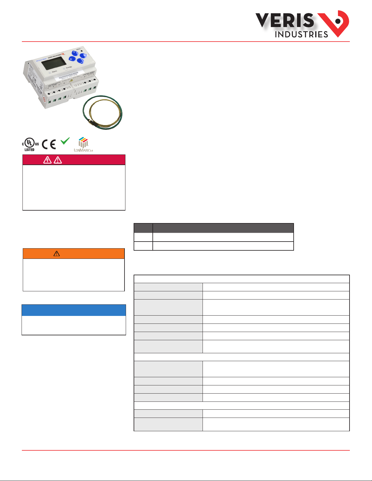
Power Monitoring
E50F2A, E50F5A
Compact Power and Energy Meters
With LON TP/FT-10 Communication
For Use Only With U018 Series Rope CTs
U018 Series
(sold separately)
RoHS
Compliant
DANGER
HAZARD OF ELECTRIC SHOCK, EXPLOSION, OR ARC FLASH
• Follow safe electrical work practices. See NFPA 70E in the USA, or applicable local codes.
• This equipment must only be installed and serviced by qualified electrical personnel.
• Read, understand and follow the instructions before installing this product.
• Turn off all power supplying equipment before working on or inside the equipment.
• Any covers that may be displaced during the installation must be reinstalled
before powering the unit.
• Use a properly rated voltage sensing device to confirm power is off.
DO NOT DEPEND ON THIS PRODUCT FOR VOLTAGE INDICATION
Failure to follow these instructions will result in death or serious injury.
A qualied person is one who has skills and knowledge related to the construction and
operation of this electrical equipment and the installation, and has received safety
training to recognize and avoid the hazards involved. NEC2009 Article 100
No responsibility is assumed by Veris Industries for any consequences arising out of the
use of this material.
Control system design must consider the potential failure modes of control paths and, for
certain critical control functions, provide a means to acheive a safe state during and after a
path failure. Examples of critical control functions are emergency stop and over-travel stop.
WARNING
LOSS OF CONTROL
∙ Assure that the system will reach a safe state during and after a control path failure.
∙ Separate or redundant control paths must be provided for critical control func tions.
∙ Test the eect of transmission delays or failures of communication links.
∙ Each implementation of equipment using communication links must be individually
and thoroughly tested for proper operation before placing it in service.
Failure to follow these instructions may cause injury, death or equipment damage.
1
For additional information about anticipated transmission delays or failures of the link, refer to
NEMA ICS 1.1 (latest edition). Safety Guidelins for the Application, Installation, and Maintenance
of Solid-State Control or its equivalent in your specic country, language, and/or location.
NOTICE
• This product is not intended for life or safety applications.
• Do not install this product in hazardous or classified locations.
• The installer is responsible for conformance to all applicable codes.
• Mount this product inside a suitable fire and electrical enclosure.
FCC PART 15 INFORMATION
NOTE: This equipment has been tested by the manufacturer and found to
comply with the limits for a class B digital device, pursuant to part 15 of
against harmful interference when the equipment is operated in a
radio frequency energy and, if not installed and used in accordance with
the instruction manual, may cause harmful interference to radio
communications. This device complies with part 15 of the FCC Rules.
Operation is subject to the following two conditions:
(1) This device may not cause harmful interference, and
(2) this device must accept any interference received, including
interference that may cause undesired operation.
Modifications to this product without the express authorization of the
manufacturer nullify this statement.
For use in a P ollution D egree 2 or be tter envi ronment on ly. A Pollutio n Degree 2
environment must control conductive pollution and the possibility of condensation or
high hum idity. Cons ider the enc losure, th e correc t use of venti lation, the rmal prop erties
of the equ ipment, an d the relati onship wi th the envir onment. In stallati on categor y:
CAT II or CAT III. P rovide a di sconnec t device to di sconnec t the meter f rom the sup ply
source. P lace this de vice in clos e proximit y to the equ ipment and w ithin eas y reach of
the oper ator, and mark i t as the disc onnecti ng device. T he disconn ecting de vice shall
meet th e relevant r equireme nts of IEC 60 947-1 and IEC 60947-3 and sh all be suit able for
the appl ication. I n the US and Can ada, discon nectin g fuse hold ers can be us ed. Provi de
overcu rrent prot ection a nd discone cting dev ice for sup ply conduc tors wit h approved
current limiting devices suitable for protecting the wiring. If the equipment is used in a
manner n ot specie d by the manu facture r, the protec tion prov ided by the d evice may
be impaired.
ZL0119 -0A Page 1 of 34 ©2013 Veris Industries USA 800.354.8556 or +1.503.598.4564 / support@veris.com 09131
Alta Labs, E nercept, Ensp ector, Hawkeye, Trus tat, Aerospo nd, Veris, and th e Veris ‘V’ log o are tradema rks or registe red tradema rks of Veris Ind ustries, L. L.C. in the USA and /or other countri es.
1
Product Overview
The E50FxA DIN Rail Power Meter provides a solution for measuring energy data with a single device. Inputs include
pulse, control power, CT, and 3-phase voltage. The E50FxA supports multiple output options, including solid
state phase loss alarm relay contacts (E50F2A only), LON, and data logging (E50F5A only). The LCD screen on the
faceplate allows instant output viewing. These meters include built-in CT integrators and CT power supplies. The
E50F2A and E50F5A work only with Veris U018 series rope style CTs.
The meter is housed in a plastic enclosure suitable for installation on T35 DIN rail according to EN50022. The E50 can
be mounted with any orientation over the entire ambient temperature range, either on a DIN rail or in a panel. The
meter is not sensitive to CT orientation to reduce installation errors.
Product Identification
Model Description
E50F2A LON output, 1 pulse input , alarm output
E50F5A LON output, data logging, 2 pulse inputs
Specifications
MEASUREMENT ACCURACY
Real Power and Energy
Reactive Power and Energy
Current
Voltage
Sample Rate
Data Update Rate
Type of Measurement
Measured AC Voltage
Metering Over-Range
Impedance
Frequency Range
CT Scaling
Measurement Input Range
Other companies’ trademarks are hereby acknowledged to belong to their respective owners.
IEC 620 53-22 Class 0.5S, ANSI C12.20 0.5%
IEC 620 53-23 Class 2, 2%
0.4% (+ 0.015% per °C deviation from 25°C) from 5% to 100% of range ;
0.8% (+0.015% per ° C deviation from 25°C) from 1% to 5% of range
0.4% (+ 0.015% per °C deviation from 25°C) from 9 0 V
2520 samples per second
1 sec
True RMS up to 1260 Hz ( 21st harmonic at 6 0 Hz); One to three phase AC
system
INPUT VO LTAGE C HARACTERI STICS
Minimum 90 V
UL Maximums: 60 0 V
+20%
2.5 MΩ
45 to 65 Hz
INPUT CUR RENT CHARACTERI STICS
20A to 50 00A
U018 series rope style CTs only ( CTs must be rated for connection to Class
1 voltage inputs)
/5 M Ω
L-N
(156 V
L-N
) for stated accuracy;
L-L
(3 47 V
L-L
L-L
); CE Maximum: 30 0 V
L-N
L-N
to 600 VAC
L-N
TM
L-L
Page 2

Installation Guide
Power Monitoring
EFA, EFA
TM
Specifications
(cont.)
CONTROL POWER
AC
5 VA max.; 9 0 V min.;
UL Maximum: 60 0 V
DC*
3 W max.; U L and CE: 125 to 30 0 VDC
Ride Through Time
Pulse
Minimum Pulse Width
Alarm Contacts
(E50F2A only)
Communication Port
Weight
IP Degree of Protection (IEC
60529)
Display Characteristics
Terminal Block Sc rew Torque
Terminal Block Wi re Size
Mounting Rail
Operating Temperature
Storage Temperature
Humidity Range
Altitude of Operation
US and Canada
Dielectric Withstand
Conducted and Radiated
Emissions
Conducted and Radiated
Immunity
Agencies: US and Canada
(cULus)
* External DC current limiting is required. See fuse recommendations.
100 msec at 120 VAC
Solid -State or mechanical contacts (current less than 1 mA)
20 msec
N.C., static output; ( 30 VAC/DC, 10 0 mA max. @ 25°C, derate 0. 56 mA per
°C above 25°C)
2-wire, LO N TP/ FT-10
MECHAN ICAL CHARACTERI STICS
0.62 lb ( 0.28 kg)
IP40 front display; IP20 Meter
Back-lit blue LCD
0.37 ft-lb ( 0.5 N· m) nominal/ 0.44 f t-lb ( 0.6 N· m) max.
24 to 14 AWG (0.2 to 2.1 mm2)
T35 ( 35mm ) DIN Rail per EN50022
OPERATING ENVIRONMENT
-30° to 70°C ( -22° to 158°F)
-4 0° to 85°C (- 40° to 185°F)
<95% RH (non-condensing)
3 km max.
COMPLIANCE INFORMATION
CAT III, Pollution degree 2;
for distribution systems up to 3 47V
CE
CAT III, Pollution degree 2;
for distribution systems up to 3 00V
Per UL 50 8, EN61010
FCC par t 15 Class B, EN5 5011/EN61000 Class B (residential and light
industrial)
EN61000 Class A ( heavy industrial)
UL508 (open type device)/ CSA 22.2 No. 14- 05
INP UT
OUTPUT
(3 47 V
L-L
); CE Maximum: 30 0 V
L-N
/600 VAC
L-N
L-N
L-L
L-N
ZL0119 -0A Page 2 of 34 ©2013 Veris Industries USA 800.354.8556 or +1.503.598.4564 / support@veris.com 09131
Alta Labs, E nercept, Ensp ector, Hawkeye, Trus tat, Aerospo nd, Veris, and th e Veris ‘V’ log o are tradema rks or registe red tradema rks of Veris Ind ustries, L. L.C. in the USA and /or other countri es.
Other companies’ trademarks are hereby acknowledged to belong to their respective owners.
Page 3

Installation Guide
Power Monitoring
EFA, EFA
TM
Table of Contents
Dimensions 4
Data Outputs 4
Product Diagram 5
Display Screen Diagram 5
Installation 6
Supported System Types 7
Wiring Symbols 7
Wiring 8
Control Power 9
Quick Setup Instructions 10
Pulse Contact Inputs 10
Solid State Output 11
LON TP/FT-10 Communications 11
User Interface Menu Abbreviations Dened 12
User Interface for Data Conguration 13
Alert/Reset Information 14
User Interface for Setup 15
Resources Available for Downloading 17
Using the LNS Plugin 17
Conguring and Commissioning Without the Plugin 24
Network Variables 25
Conguration Properties 30
Troubleshooting 34
China RoHS Compliance Information 34
ZL0119 -0A Page 3 of 34 ©2013 Veris Industries USA 800.354.8556 or +1.503.598.4564 / support@veris.com 09131
Alta Labs, E nercept, Ensp ector, Hawkeye, Trus tat, Aerospo nd, Veris, and th e Veris ‘V’ log o are tradema rks or registe red tradema rks of Veris Ind ustries, L. L.C. in the USA and /or other countri es.
Other companies’ trademarks are hereby acknowledged to belong to their respective owners.
Page 4
Installation Guide
Power Monitoring
EFA, EFA
TM
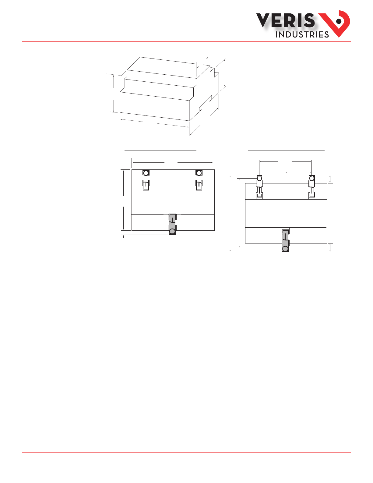
Dimensions
1.8”
(45mm)
1.9”
(48mm)
2.3”
(59mm)
1.5”
(39mm)
4.2”
(107mm)
3.6”
(91mm)
Bottom View (DIN Mount Option) Bottom View (Screw Mount Option)
2.4 “
(61 mm)
+
0.2 “
(4 mm)
3.6 “
(91 mm)
4.2 “
(107 mm)
3.9“
(99 mm)
4.3 “
(109 mm)
1.2 “
(31 mm)
++
0.3 “
(8 mm)
0.4 “
(10 mm)
Data Outputs
Full Data Set (FDS)
Power (kW)
Energy (kWh)
Congurable for CT & PT ratios, system type, and passwords
Diagnostic alerts
Current: 3-phase average
Volts: 3-phase average
Current: by phase
Volts: by phase Line-Line and Line-Neutral
Power: Real, Reactive, and Apparent 3-phase total and per phase
Power Factor: 3-phase average and per phase
Frequency
Power Demand: Most Recent and Peak
Demand Conguration: Fixed, Rolling Block, and External Sync
Real Time Clock: user congurable
Data Logging (E50F5A only, includes all FDS outputs plus)
3 user congurable log buers: each buer holds 5760 32-bit entries
(User congures which 3 data points are stored in these buers)
User congurable logging interval
(When congured for a 15 minute interval, each buer holds 60 days of data)
Continuous and Single Shot logging modes: user selectable
Auto write pause: read logs without disabling the meter’s data logging mode
ZL0119 -0A Page 4 of 34 ©2013 Veris Industries USA 800.354.8556 or +1.503.598.4564 / support@veris.com 09131
Alta Labs, E nercept, Ensp ector, Hawkeye, Trus tat, Aerospo nd, Veris, and th e Veris ‘V’ log o are tradema rks or registe red tradema rks of Veris Ind ustries, L. L.C. in the USA and /or other countri es.
Other companies’ trademarks are hereby acknowledged to belong to their respective owners.
Page 5
Installation Guide
Power Monitoring
EFA, EFA
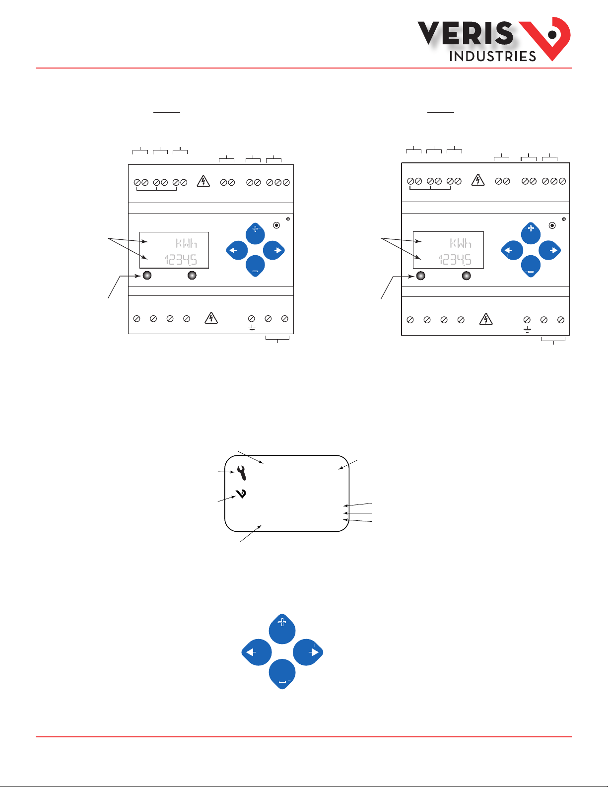
Product Diagrams
TM
Two 5-character rows
of display text.
Top row alphanumeric;
Bottom row numeric only
The red Alarm LED lights
when any of the 3 phase
voltages drop below the
selected threshold.
E50F2A
IA
IB
IC
X2 X1 X2 X1 X2 X1
(X2) A (X1) (X2) B (X1) (X2) C (X1)
Alarm Energy
VOLTAGE INPUTS
CAT III 50/60 Hz
A B C N 1 2
VA
UL: 90V
- 600V
L-N
VB
VC
Neutral
CE: 90V
L-L
Alarm Output
- 300V
L-N
L-N
Pulse Input
+
–
CONTROL POWER
0.1A 50/60 Hz
EMC Ground
SERVICE
LON FT
Control
Shield
S
Two 5-character rows
of display text.
Top row alphanumeric;
Bottom row numeric only
The red Alarm LED lights
when any of the 3 phase
voltages drop below the
selected threshold.
The green Energy LED lights
when the pulse 1 input
contacts are active or closed.
Power
E50F5A
IA
IB
IC
X2 X1 X2 X1 X2 X1
(X2) A (X1) (X2) B (X1) (X2) C (X1)
Alarm Energy
VOLTAGE INPUTS
CAT III 50/60 Hz
A B C N 1 2
VA
UL: 90V
- 600V
L-N
VB
VC
Neutral
Pulse Input 1
Pulse Inputs
1 2 S
CE: 90V
- 300V
L-L
L-N
L-N
Pulse Input 2
+
–
CONTROL POWER
0.1A 50/60 Hz
EMC Ground
SERVICE
LON FT
Control
Shield
Power
Display Screen
Diagram
LCD Screen:
Screen Name or Units
Diagnostic Alert
Logo
Numeric Data
Buttons:
(Left)
Back
(Up)
Select
+
–
(Down)
Select
♥
Tx
Rx
ERR
(Right)
Alive Indicator
RS-485 Equipped Units Only:
Transmit Data
Receive Data
Receive Data Error
Next
ZL0119 -0A Page 5 of 34 ©2013 Veris Industries USA 800.354.8556 or +1.503.598.4564 / support@veris.com 09131
Alta Labs, E nercept, Ensp ector, Hawkeye, Trus tat, Aerospo nd, Veris, and th e Veris ‘V’ log o are tradema rks or registe red tradema rks of Veris Ind ustries, L. L.C. in the USA and /or other countri es.
Other companies’ trademarks are hereby acknowledged to belong to their respective owners.
Page 6
Installation Guide
Power Monitoring
EFA, EFA
TM
Installation
Disconnect power prior to installation.
Reinstall any covers that are displaced during the installation before powering the unit.
Mount the meter in an appropriate electrical enclosure near equipment to be monitored.
Do not install on the load side of a Variable Frequency Drive (VFD), aka Variable Speed Drive (VSD)
or Adjustable Frequency Drive (AFD).
Observe correct CT orientation.
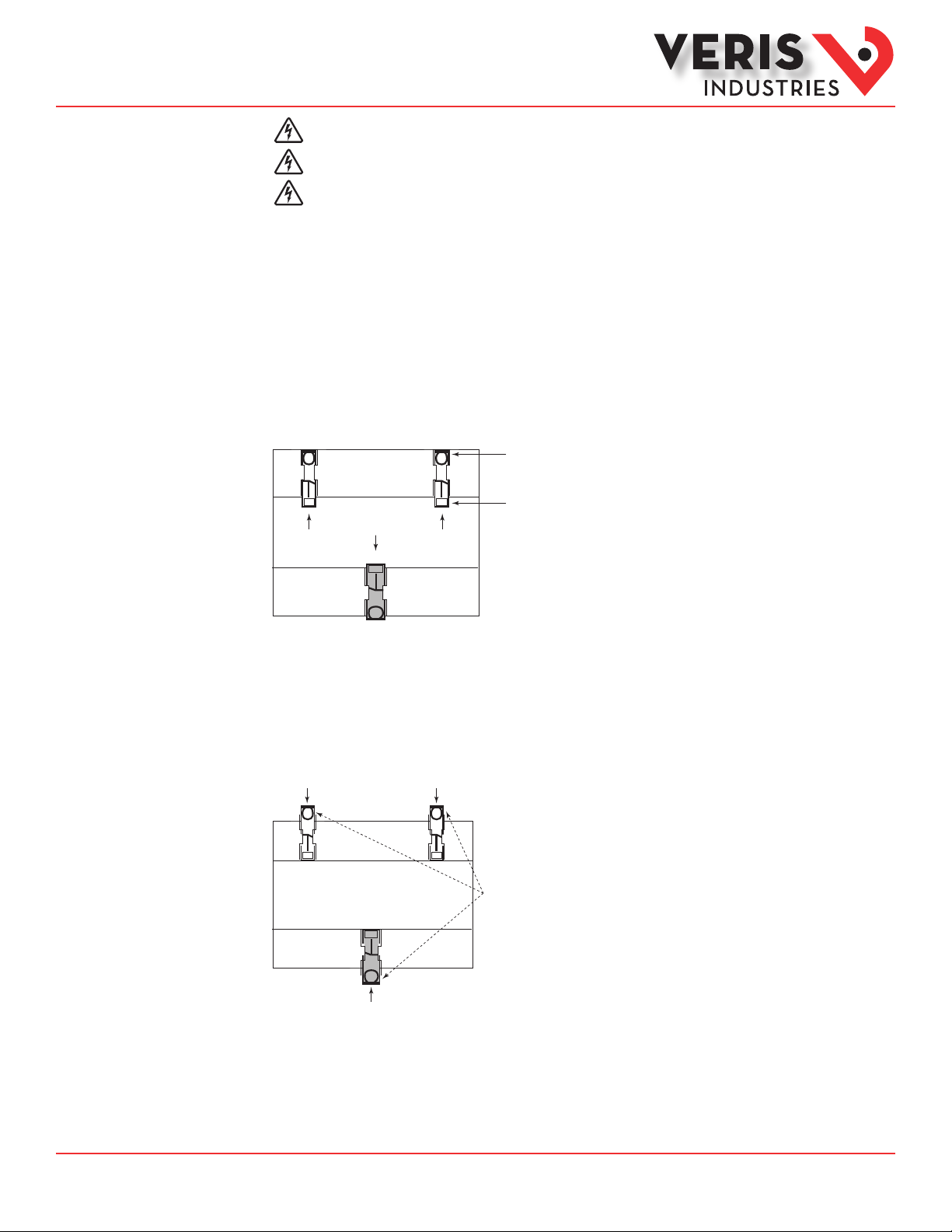
The meter can be mounted in two ways: on standard 35 mm DIN rail or screw-mounted to the interior surface of the enclosure.
A. DIN Rail Mounting
1. Attach the mounting clips to the underside of the housing by sliding them into the slots from the inside. The stopping pegs
must face the housing, and the outside edge of the clip must be ush with the outside edge of the housing.
2. Snap the clips onto the DIN rail. See the diagram of the underside of the housing (below).
Clip flush with
outside edge
Snap onto
Insert clips from inside
DIN rail
3. To reduce horizontal shifting across the DIN rail, use two Veris AV02 end stop clips.
B. Screw Mounting
1. Attach the mounting clips to the underside of the housing by sliding them into the slots from the outside. The stopping pegs
must face the housing, and the screw hole must be exposed on the outside of the housing.
2. Use three #8 screws (not supplied) to mount the meter to the inside of the enclosure. See the diagram of the underside of the
housing (below).
Insert clips from outside
Screw holes
exposed for
mounting
ZL0119 -0A Page 6 of 34 ©2013 Veris Industries USA 800.354.8556 or +1.503.598.4564 / support@veris.com 09131
Alta Labs, E nercept, Ensp ector, Hawkeye, Trus tat, Aerospo nd, Veris, and th e Veris ‘V’ log o are tradema rks or registe red tradema rks of Veris Ind ustries, L. L.C. in the USA and /or other countri es.
Other companies’ trademarks are hereby acknowledged to belong to their respective owners.
Page 7
Installation Guide
Power Monitoring
EFA, EFA
TM
Supported System
Types
The meter has a number of dierent possible system wiring congurations (see Wiring Diagrams section). To congure the meter,
set the System Type via the User Interface, LON variable cpSystemType. The System Type tells the meter which of its current and
voltage inputs are valid, which are to be ignored, and whether neutral is connected. Setting the correct System Type prevents
unwanted energy accumulation on unused inputs, selects the formula to calculate the Theoretical Maximum System Power, and
determines which phase loss algorithm is to be used. The phase loss algorithm is congured as a percentage of the Line-to-Line
System Voltage (except when in System Type 10) and also calculates the expected Line to Neutral voltages for system types that
have Neutral (12 & 40).
Values that are not valid in a particular System Type display as “----” on the User Interface or as QNAN in the LON variables.
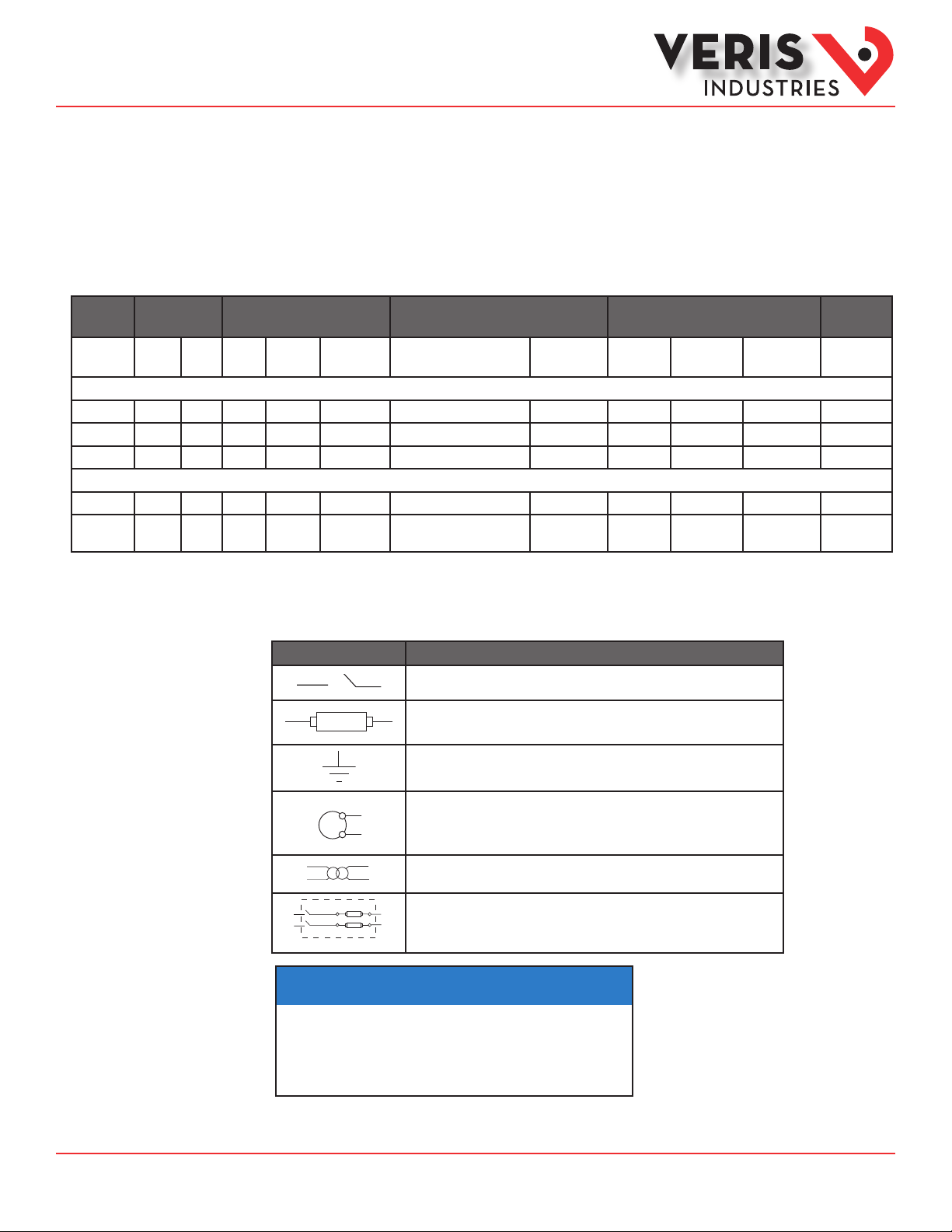
CTs Voltage Connections System Type Phase Loss Measurements Wiring
Number of
wires
Single-Phase Wiring
2 1 A 2 A, N L-N 10 1L + 1n AN 1
2 1 A 2 A, B L- L 11 2L AB 2
3 2 A, B 3 A, B, N L-L with N 12 2L + 1n AB AN, BN AN-BN 3
Three-Phase Wiring
3 3 A, B, C 3 A, B, C Delta 31 3L AB, BC, CA AB-BC-CA 4
4 3 A, B, C 4 A, B, C, N Grounded
Qty ID Qty ID Type LON variable cpSystemType User Interface:
SETUP>S SYS
40 3L + 1n AB, BC, CA AN, BN, CN AN-BN-CN &
Wye
VLL VLN Balance Diagram
AB-BC-CA
Diagram
number
5, 6
Wiring Symbols
To avoid distortion, use parallel wires for control power and voltage inputs.
The following symbols are used in the wiring diagrams on the following pages.
Symbol Description
Voltage Disconnect Switch
Fuse (installer is responsible for ensuring compliance with local requirements. No
fuses are included with the meter.)
Earth ground
X1
Current Transducer
Potential Transformer
Protection containing a voltage disconnect switch with a fuse or disconnect circuit
breaker. The protection device must be rated for the available short-circuit current at
the connection point.
NOTICE
• This product is designed only for use with U018 series current transducers (CTs).
• DO NOT USE CURRENT OUTPUT (e.g. 5A) CTs ON THIS PRODUCT.
Failure to follow these instructions can result in equipment damage.
RISK OF EQUIPMENT DAMAGE
ZL0119 -0A Page 7 of 34 ©2013 Veris Industries USA 800.354.8556 or +1.503.598.4564 / support@veris.com 09131
Alta Labs, E nercept, Ensp ector, Hawkeye, Trus tat, Aerospo nd, Veris, and th e Veris ‘V’ log o are tradema rks or registe red tradema rks of Veris Ind ustries, L. L.C. in the USA and /or other countri es.
Other companies’ trademarks are hereby acknowledged to belong to their respective owners.
Page 8
Installation Guide
Power Monitoring
EFA, EFA
TM
Wiring
WARNING
RISK OF ELECTRIC SHOCK OR PERMANENT EQUIPMENT DAMAGE
CT negative terminals are referenced to the meter’s neutral and may be at elevated voltages
· Do not contact meter terminals while the unit is connected
· Do not connect or short other circuits to the CT terminals
Failure to follow these instructions may cause injury, death or equipment damage.
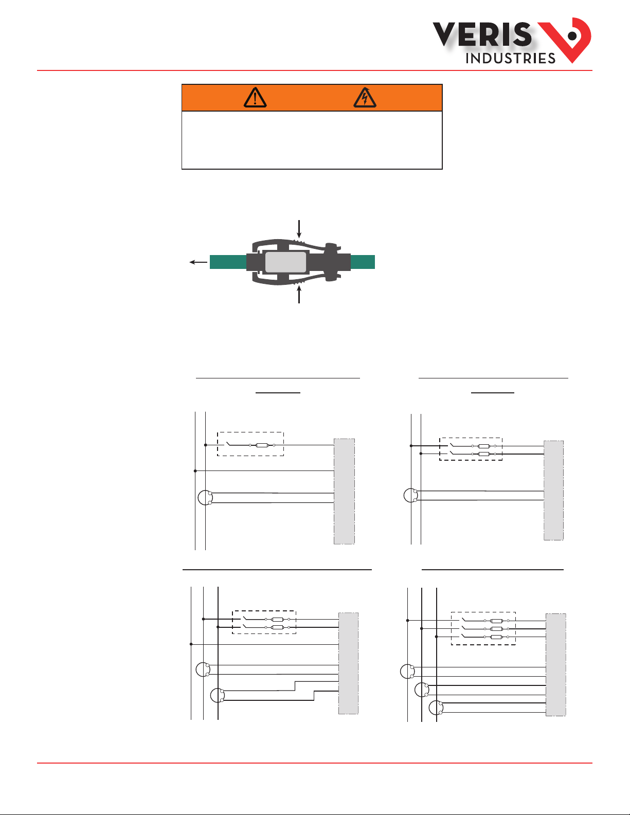
1. Connect the CT output leads to the E50FxA meter inputs according to the following diagrams. The white wire is the X1 lead.
2. Squeeze the ribbed sections of the CT connector and pull the rope out of the connector to open.
3. Wrap the rope style CT around the conductor to be monitored.
4. Snap the connector back together securely, ensuring there is no dust or debris in the closure area.
Diagram 1: 1-Phase Line-to-Neutral 2- Wire
System 1 CT
N L1
Use System Type 10 (1L + 1n)
Diagram 2: 1-Phase Line-to-Line 2-Wire
System 1 CT
Use System Type 11 (2L)
L1 L2
A
B
C
N
X1
X2
White
Black
X1
A
X2
X1
B
X2
X1
C
X2
Diagram 3: 1-Phase Direct Voltage Connection 2 CT
N
L1 L2
X1
X2
Use System Type 12 (2L + 1n) Use System Type 31 (3L)
A
B
C
N
White
Black
X1
X2
White
Black
X1
A
X2
X1
B
X2
X1
C
X2
X1
X2
White
Black
Diagram 4: 3-Phase 3-Wire 3 CT no PT
L1 L2 L3
X1
X1
X2
X2
White
Black
White
X1
X2
Black
White
Black
A
B
C
N
X1
A
X2
X1
B
X2
X1
C
X2
A
B
C
N
X1
A
X2
X1
B
X2
X1
C
X2
ZL0119 -0A Page 8 of 34 ©2013 Veris Industries USA 800.354.8556 or +1.503.598.4564 / support@veris.com 09131
Alta Labs, E nercept, Ensp ector, Hawkeye, Trus tat, Aerospo nd, Veris, and th e Veris ‘V’ log o are tradema rks or registe red tradema rks of Veris Ind ustries, L. L.C. in the USA and /or other countri es.
Other companies’ trademarks are hereby acknowledged to belong to their respective owners.
Page 9
Installation Guide
Power Monitoring
EFA, EFA
TM
Wiring (cont.)
Control Power
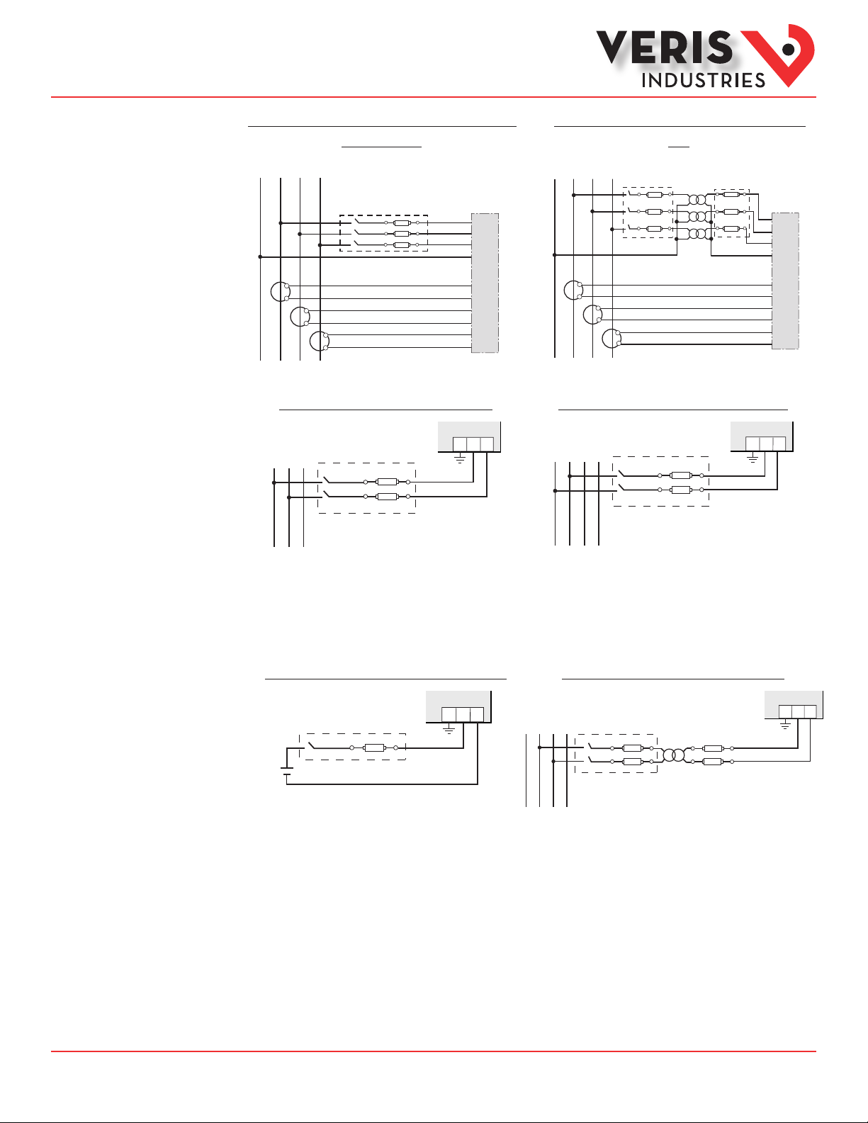
Diagram 5: 3-Phase 4-Wire Wye Direct Voltage Input
Connection 3 CT
Use System Type 40 (3L + 1n)
L1N L2 L3
A
B
C
N
X1
X2
X1
X2
X1
X2
White
Black
White
Black
White
Black
X1
A
X2
X1
B
X2
X1
C
X2
Direct Connect Control Power (Line to Line)
L1
L2 L3
1 2G
Diagram 6: 3-Phase 4-Wire Wye Connection 3 CT
3 PT
Use System Type 40 (3L + 1n)
L1N L2 L3
A
B
C
N
X1
X1
X2
X2
X1
X2
White
Black
White
Black
White
Black
X1
A
X2
X1
B
X2
X1
C
X2
Direct Connect Control Power (Line to Neutral)
L1N L2 L3
1 2G
Line to Line from 90 VAC to 600 VAC (UL). In UL installations the
Line to Neutral from 90 VAC to 347 VAC (UL) or 300 VAC (CE)
lines may be oating (such as a delta). If any lines are tied to an
earth (such as a corner grounded del ta), see the Line to Neutral
installation limits. In CE compliant installations, the lines must
be neutral (earth) referenced at less than 300 VAC
Direct Connect Control Power (DC Control Power)
L-N
Control Power Transformer (CPT) Connection
1 2G
L1N L2 L3
DC Control Power from 125 VDC to 300 VDC
(UL and CE max.)
The Control Power Transformer may be wired L-N or L-L. Output to
meet meter input requirements
Fuse Recommendations
Keep the fuses close to the power source (obey local and national code requirements).
For selecting fuses and circuit breakers, use the following criteria:
• Select current interrupt capacity based on the installation category and fault current capability.
• Select over-current protection with a time delay.
• Select a voltage rating sucient for the input voltage applied.
• Provide overcurrent protection and disconnecting means to protect the wiring. For AC installations, use Veris AH02,
AH03, AH04, or equivalent. For DC installations, provide external circuit protection. Suggested: 0.5 A, time delay fuses.
• The earth connection (G) is required for electromagnetic compatibility (EMC) and is not a protective earth ground.
1 2G
ZL0119 -0A Page 9 of 34 ©2013 Veris Industries USA 800.354.8556 or +1.503.598.4564 / support@veris.com 09131
Alta Labs, E nercept, Ensp ector, Hawkeye, Trus tat, Aerospo nd, Veris, and th e Veris ‘V’ log o are tradema rks or registe red tradema rks of Veris Ind ustries, L. L.C. in the USA and /or other countri es.
Other companies’ trademarks are hereby acknowledged to belong to their respective owners.
Page 10
Installation Guide
Power Monitoring
EFA, EFA
TM
Quick Setup
Instructions
These instruc tions assume the meter is set to factory defaults. If it has been previously congured, check all optional values.
A. To Navigate to the Setup screens:
+
+
1. Press
or – repeatedly until SETU P screen appears.
2. Press to get to the PASWD screen.
+
3. Press to move through the digits. Use the
+
or – buttons to enter your password (the default is 00000).
4. Press to move to the rst Setup screen (S CT)
+
+
5. Use
or – to select the parameter screen you want to set.
+
6. After you set the parameters you want, use
+
or – to select the next Setup screen or to exit the Setup screens (return to
SETU P ).
B. To Enter the CT (Current Transducer) output voltage and CT size ranges:
+
1. Press to go to the CT SZ screen and through the digits. Use
+
or – to select the CT size in amps (default is 100). accept
the value and
2. Press to accept the value and go back to the S CT screen.
C. To Enter the service type to be monitored:
1. Navigate to the S SYS (Set System) Setup screen (see section A above).
+
2. Press to go to the SY STM screen. Use
+
or – to select the conguration (see wiring diagrams - default is 3L-1N).
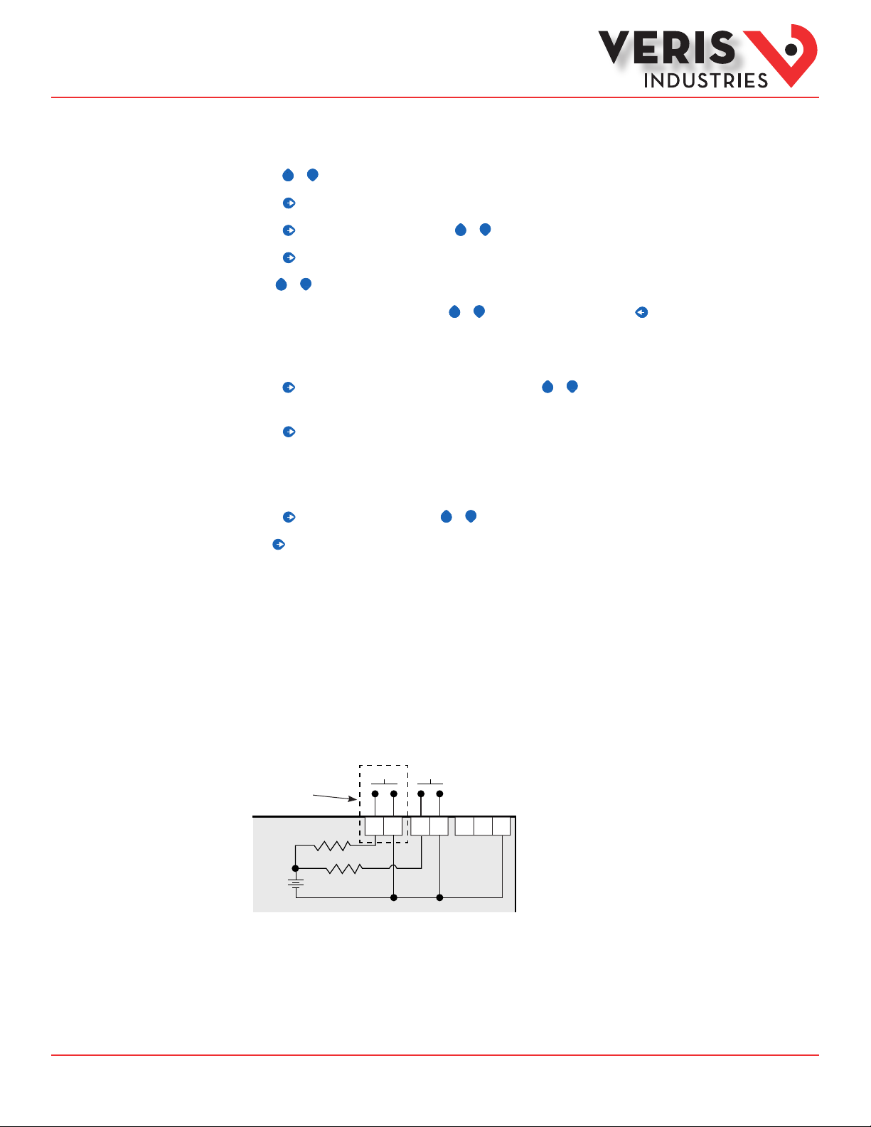
Pulse Contact Inputs
Press to go back to the S SYS screen.
For full setup instructions, see the conguration instructions on the following pages.
The E50F5A has two inputs with pulse accumulators for solid state or mechanical contacts in other sensors, such as water or gas
ow meters. The E50F2A has one pulse input. These inputs are isolated from the measured circuits. The communication signals,
including the shield terminal, are AC-coupled. Use with contacts that do not require current to remove oxidation.
Pulse Input
E50F5A only
+
4-10 VDC
nominal
Contacts
~10 kΩ
Output
Comm
Ground
SComm
Equivalent
Circuit
ZL0119 -0A Page 10 of 34 ©2013 Veris Industries USA 800.354.8556 or +1.503.598.4564 / support@veris.com 09131
Alta Labs, E nercept, Ensp ector, Hawkeye, Trus tat, Aerospo nd, Veris, and th e Veris ‘V’ log o are tradema rks or registe red tradema rks of Veris Ind ustries, L. L.C. in the USA and /or other countri es.
Other companies’ trademarks are hereby acknowledged to belong to their respective owners.
Page 11
Installation Guide
Red
Black
Gray
Use 14-24 gauge wire
Power Monitoring
EFA, EFA
TM
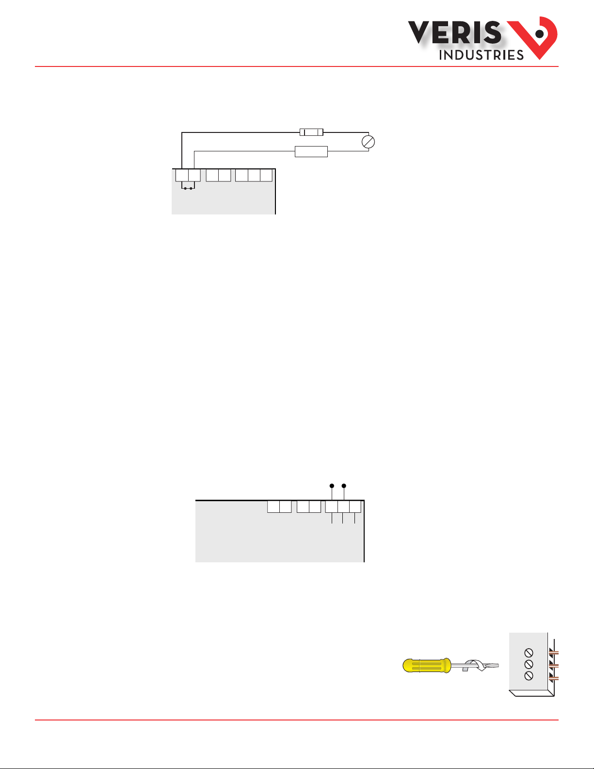
Solid State Output
The E50F2A has one normally closed (N.C.) alarm output.* See the Setup section for conguration information.
Over-Current Protective Device**
(not supplied)
≤ 100 mA
Power So urce
~
=
3-30 VDC
6-3 0 VAC
S
Alarm
Pulse Comm
The solid state pulse outputs are rated for 30 VAC/DC nom.
The maximum load current is 100 mA at 25°C. Derate 0.56 mA per °C above 25°C.
* While the relay used for the Phase Loss contact is normally closed (contacts are closed when the meter is not powered), closure
indicates the presence of an alarm; either loss of phase, when the meter is powered, or loss of power when the meter is not. The
contacts are open when the meter is powered and no phase loss alarm conditions are present.
** The over-current protective device must be rated for the short circuit current at the connection point.
All pulse inputs/outputs and communication circuits are only intended to be connected to non-hazardous circuits (SELV or Class 2).
Do not connect to hazardous voltages.
Lon TP/FT-10
Communications
• Use this meter in either Free Topology or Bus Topology LonWorks network congurations.
• Twisted pair connections to the meter are not polarity sensitive.
• Attach the meter at any point in a Free Topology conguration, but the total network cable length must be less than
500 meters.
• Free Topology congurations require one terminator (Echelon TP/FT-10 Free Topology Terminator or equivalent), which
can be attached at any point in the network.
• In Bus Topology congurations, connect loads sequentially (in a daisy chain), except for stubs, which must be less than
3 meters in length. The total network cable length must be less than 2700 meters.
• Bus Topology congurations require two terminators (Echelon TP/FT -10 Free Topology Terminator or equivalent, one
at at each end of the network.
• The Shield connection is not internally connected to the ground connection on the meter.
LON-FT Shield
For all terminals:
• When tightening terminals, apply the correct torque: 0.37 to 0.44 ft·lb (0.5-0.6 N·m).
• Use 14-24 gauge (2.1-0.2 mm2) wire.
0.37–0.44 ft•lb
(0.5–0.6 N•m)
ZL0119 -0A Page 11 of 34 ©2013 Veris Industries USA 800.354.8556 or +1.503.598.4564 / support@veris.com 09131
Alta Labs, E nercept, Ensp ector, Hawkeye, Trus tat, Aerospo nd, Veris, and th e Veris ‘V’ log o are tradema rks or registe red tradema rks of Veris Ind ustries, L. L.C. in the USA and /or other countri es.
Other companies’ trademarks are hereby acknowledged to belong to their respective owners.
Page 12

Installation Guide
Power Monitoring
EFA, EFA
TM
User Interface (UI)
Menu Abbreviations
Defined
The user can set the display mode to either IEC or IEEE notation in the SETUP menu.
Main Menu
IEC IEEE Description
D D Demand
MAX M Maximum Demand
P W Present Real Power
Q VAR Present Reactive Power
S VA Present Apparent Power
A A Amps
UAB, UBC, UAC VAB, VBC, VAC Voltage Line to Line
V VLN Voltage Line to Neutral
PF PF Power Factor
U VLL Voltage Line to Line
HZ HZ Frequency
KSh KVAh Accumulated Apparent
Energy
KQh KVA Rh Accumulated Reactive
Energy
KPh K Wh Accumulated Real Energy
PLOSS PLOSS Phase Loss
LOWPF LOWPF Low Power Fac tor Error
IEC IEEE Description
F ERR F ERR Frequency Error
I OVR I OVR Over Current
V OVR V OVR Over Voltage
PULSE PULSE kWh Pulse Output Overrun
_PHASE _PHASE Summary Data for 1, 2, or 3
ALERT ALERT Diagnostic Alert Status
INFO INFO Unit Information
MODEL MODEL Model Number
OS OS Operating System
RS RS Reset System
SN SN Serial Number
RESET RESET Reset Data
PASWD PASWD Enter Reset or Setup
ENERG ENERG Reset Energy Accumulators
DEMND DEMND Reset Demand Maximums
Main Menu
(conguration error)
active phases
Password
ZL0119 -0A Page 12 of 34 ©2013 Veris Industries USA 800.354.8556 or +1.503.598.4564 / support@veris.com 09131
Alta Labs, E nercept, Ensp ector, Hawkeye, Trus tat, Aerospo nd, Veris, and th e Veris ‘V’ log o are tradema rks or registe red tradema rks of Veris Ind ustries, L. L.C. in the USA and /or other countri es.
Other companies’ trademarks are hereby acknowledged to belong to their respective owners.
Page 13

Installation Guide
Power Monitoring
EFA, EFA
User Interface for
TM
Data Configuration
M KVA
MKVAR
DEMND
Maximum
Demand (S)
Apparent Power
Maximum
Demand (Q)
Reactive Power
CPHAS
C KWh
C PF
C KVA
CKVAR
_PHAS
HZ
Frequency
BPHAS
B KWh
B PF
B KVA
APHAS
A KWh
A PF
A KVA
3 KWh
Real Energy
Accumulated
3 PF
(Average of
Power Factor
Active Phases)
Power (S)
3 KVA
Total Apparent
ENRGY
3KVAR
BKVAR
AKVAR
Power (Q)
Total Reactive
PULS2
Pulse Counter 2
(Not used on E50F2)
To:
>>> Scroll When Idle >>>
Maximum
Real Power
M KW
Demand (P)
Present
D KVA
Demand (S)
Apparent Power
Present
Demand (Q)
DKVAR
Reactive Power
Present
Real Power
Demand (P)
D KW
SETUP
DEMND
Demand
C KWC VLN
C VAC
C A
CPHAS
3 Phase
Phase C:
B KWB VLN
B VBC
B A
BPHAS
Phase B:
2 & 3 Phase
Systems Only
A KW
A VLN
A VAB
A A
APHAS
Phase A:
Systems Only
All Systems
Total Real
3 KW
3 VLN
(Average of Active
Volts Line-Neutral (V)
3 VLL
(Average of Active
Volts Line-Line (U)
3 A
Amps (A)
(Average of
_PHAS
Summary Data
1, 2, or 3 Phase
Power (P)
Phases)
Phases)
Active Phases)
PULS1
KVAh
KVARh
KWh
ENRGY
Energy
Accumulators
Pulse Counter 1
Accumulated
Apparent Energy
Accumulated
Reactive Energy
Real Energy
Accumulated
and Counters
(Sh)
(Qh)
(Ph)
To:
ALERT
ZL0119 -0A Page 13 of 34 ©2013 Veris Industries USA 800.354.8556 or +1.503.598.4564 / support@veris.com 09131
Alta Labs, E nercept, Ensp ector, Hawkeye, Trus tat, Aerospo nd, Veris, and th e Veris ‘V’ log o are tradema rks or registe red tradema rks of Veris Ind ustries, L. L.C. in the USA and /or other countri es.
Other companies’ trademarks are hereby acknowledged to belong to their respective owners.
Page 14

Installation Guide
Power Monitoring
EFA, EFA
Alert/Reset
Information
To: ENRGY
TM
Alert Status
(check if
Wrench on
LCD)
Unit
Information
Reset
Data
Setup
Meter
ALERT
INFO
RESET
SETUP
PLOSS
-------A b C
Phase Loss
A B C
LOWPF
-------A b C
Low Power Factor
A B C
F ERR
-------A
Frequency Out
of Range
A
Display “nOnE” if no alerts
MODEL OS SNRS
Model
Number
Operating
System
Reset
System
Back
PASWD
--------
0
0000
Enter Reset
Password
ENERG
--------
rES
Reset Energy
Accumulators to 0
Reset Demand
Maximums to Present
PASWD
--------
0
0000
Enter Setup
Password
DEMND
--------
rES
I OVR
-------A b C
Current
Out of Range
A B C
Serial
Number
COUNT
rES
Reset Pulse
Counters to 0
--------
V OVR
-------A b C
Voltage
Out of Range
A B C
INFO
RESET
To Setup
PULSE
------- Error
Not used on
E50Fx devices
ALERT
PASWD – Enter the Reset Password
(configured in the setup menu).
ENERG – Reset all Energy
Accumulators (Wh, VARh, VAh) to 0.
Press “+” or “-“ to Reset.
DEMND – Reset all Maximum
Demand (W, VAR, VA) to the present
Demand. Press “+” or “-“ to Reset.
COUNT – Reset the pulse counters.
Press “+” or “-“ to Reset.
To: DEMND
ZL0119 -0A Page 14 of 34 ©2013 Veris Industries USA 800.354.8556 or +1.503.598.4564 / support@veris.com 09131
Alta Labs, E nercept, Ensp ector, Hawkeye, Trus tat, Aerospo nd, Veris, and th e Veris ‘V’ log o are tradema rks or registe red tradema rks of Veris Ind ustries, L. L.C. in the USA and /or other countri es.
Other companies’ trademarks are hereby acknowledged to belong to their respective owners.
Page 15

Installation Guide
Power Monitoring
EFA, EFA
UI for Setup
To Setup p. 2 “SPASS”
TM
Transformer
Back To SETUP
Back
Current
Back
System
Type
Back
Potential
Transformer
Back
Sytem
Voltage
S CT
S SYS
S PT
S V
CT SZ
--------
00
1
Next
SYSTM
--------
3L-1n
3L
2L-1n
2L
1L-1n
RATIO
--------
001
V LL
--------
0
0600
.00
Next
Next
Set Current Transducer:
CT SZ - CT Size: in Amps. Maximum is 32000 Amps.
Set System Configuration:
SYSTM: + or – to step through the following System Type options:
System Reg 130 CTs Description
3L-1n 40 3 Wye Three Phase: A, B, & C with Neutral (Default).
3L 31 3 Delta Three Phase: A, B & C; no Neutral
2L-1n 12 2 Single Split Phase: A & B with Neutral
2L 11 1 Single Phase: A & B; no Neutral
1L-1n 10 1 Single Phase: A to Neutral
Next
Set Potential Transfomer Ratio:
RATIO – Potential transformer step down is RATIO:1. Default is 1:1
(No PT installed). See Wiring Diagrams section. Set this value before
setting the system voltage to establish the proper range of System
Voltage values.
Set System Voltage:
V LL – The nominal Line to Line Voltage for the system. This is used
by the meter to calculate the theoretical maximum system power,
and as the reference voltage for setting the Phase Loss threshold.
Maximum is 32000 Volts. For system type 1+N (10), this is a Line to
Neutral Voltage, indicated by “V LN”. Note: the meter will reject settings
that are not within the meter’s operating range when divided by the PT ratio.
System Power:
MX KW – The theoretical Maximum System Power is calculated by the
meter from the System Voltage, CT size, and System Type. Power Factor
is assumed to be unity. The value of System Power is used to determine
which combinations of pulse weight and duration are valid and will keep up
with the maximum power the meter will see. This value is read only.
Default values are in Bold
S PWR
Back
Sytem
Voltage
To Setup p. 2 “SPLOS”
MX KW
--------
103.92
Next
† When leaving this pa rameter screen using the right but ton ( ), the display wi ll briey indicate “SAvEd)” to conrm that any cha nges made have been accepted.
ZL0119 -0A Page 15 of 34 ©2013 Veris Industries USA 800.354.8556 or +1.503.598.4564 / support@veris.com 09131
Alta Labs, E nercept, Ensp ector, Hawkeye, Trus tat, Aerospo nd, Veris, and th e Veris ‘V’ log o are tradema rks or registe red tradema rks of Veris Ind ustries, L. L.C. in the USA and /or other countri es.
Other companies’ trademarks are hereby acknowledged to belong to their respective owners.
Page 16

Installation Guide
Power Monitoring
EFA, EFA
UI for Setup (cont.)
To Setup p. 1 “S PWR”
Back
Back
SPLOS
Phase
Loss
SDMND
Demand
VOLTS
--------
0.1
0
INTRV
-------6
5
4
3
2
1
IMBAL
--------
0.2
Next
SEC
--------
0
0900
Next
TM
Set Phase Loss:
VOLTS - Phase Loss Voltage: Phase Loss Voltage Threshold in
percent of system voltage. Any phase (as configured by the System
Type) whose level drops below this threshold triggers a Phase Loss alert.
5
For example, with the system type set to 40 (3L+N) and the System
voltage set to 480V L-L, the L-N voltage for each phase is 277V.
When this threshold is set to 10%, if any phase drops to less than 10%
of 277V (less than 27.7V), or if any L-L voltage drops to less than 10% of
480V (less than 48V), the corresponding phase loss alarm activates.
IMBAL - Phase Loss Imbalance: Phase Loss Imbalance Threshold in
percent is the fractional difference in Line to Line voltages above which
Phase Loss Alarm is on. For a 3-phase Y(3+N) system (type 40), both
Line to Neutral and Line to Line voltages are tested. In a 3-phase delta
system (type 31), only the Line to Line voltages are examined. In a single
split-phase (2+N) system (type 12), only the Line to Neutral voltages are
compared. For system types 1+N (10) and 2 (11), imbalance is not tested.
Set Demand Interval:
INTRV - The number of Sub-Intervals (1 to 6) in a Demand Interval.
Default is 1 (block demand).
SEC - Sub-Interval length in seconds. Default is 900 (15 minutes).
Set to 0 for external sync-to-comms.
UNITS
Back
Back
Passwords
To Setup page 1 “S CT”
† When leaving this pa rameter screen using the right but ton ( ), the display wi ll briey indicate “SAvEd)” to conrm that any cha nges made have been accepted.
S DIS
Display
Units
SPASS
Setup
--------
IEEE
IEC
Next
SETUP
--------
0
0000
RESET
--------
0
0000
Next
Set Display Units: +/- to switch between:
IEEE – VLL VLN W VAR VA Units.
IEC – U V P Q S Units.
Set Passwords:
SETUP - The Password to enter the SETUP menu.
RESET - The Password to enter the RESET menu.
ZL0119 -0A Page 16 of 34 ©2013 Veris Industries USA 800.354.8556 or +1.503.598.4564 / support@veris.com 09131
Alta Labs, E nercept, Ensp ector, Hawkeye, Trus tat, Aerospo nd, Veris, and th e Veris ‘V’ log o are tradema rks or registe red tradema rks of Veris Ind ustries, L. L.C. in the USA and /or other countri es.
Other companies’ trademarks are hereby acknowledged to belong to their respective owners.
Page 17

Installation Guide
Power Monitoring
EFA, EFA
TM
Resources Available
for Downloading
Using the LNS
Plugin
The following resources are available at the Veris website, www.veris.com under Design Resources -> Protocol Info -> LonWorks.
Plugin
The E50 LNS plugin oers the simplest method to congure the E50FxA meter. The plugin displays all of the conguration options
and installs the Veris Resource File Set and device template. The LNS Network Operating System and a plugin Director (to launch
the plugin, such as LonMaker) are both required to run the plugin.
Device Interface Files
The E50 device interface les (.XIF, .XFB in binar y form) are required to properly commission a device. Creating a device template
from these les allows the network to correctly name the network variables and conguration properties. Download and save the
device interface les to C:\LonWorks\import\Veris Industries\. Alternatively, the E50 LNS Plugin installs these les automatically
(no need to download the les separately).
Resource File Set
All of the meter’s network variables (except nvoLoggedData) use standard network variable types (SNVTs). However, the
conguration proper ties to set the meter installation details (CT size, system type, system voltage, etc.) are user-dened
conguration proper ties (UCPTs). The Veris website includes a manufacturer-scoped resource le set to recognize these types, but
they are not necessarily required. Commissioning and conguring options are explained below, and the need for the resource les
depends on the situation and user preference. The E50 LNS Plugin automatically installs the Veris Resource File Set (no need to
download these les separately). Note: If using resource les, install them before importing the device template into a network.
The following instructions are written for the Veris E50 LNS Plugin using LonMaker. If using a dierent integration tool, replace the
specic steps that have actions in LonMaker with equivalent procedures for the integration tool in use (see documentation for the
tool).
Installation Instructions
1. Download the “Veris E50 LNS Plugin Vx.x Installer.zip le from the Veris website, found under Design Resources->Protocol
Info->LonWorks.
2. Extract all les from the zip.
3. Double click the setup.exe le to start the installer. If installing on Windows 7 or Windows Vista, when the User Access Control
dialog appears, click “Allow” to give the installer administrative privileges.
4. Install the Microsoft .NET Framework 2.0 (or above) at this point. Follow the prompts, and then the plugin installer will begin.
5. Click Next and select a folder to install the plugin to. It is recommended to keep the default of LonWorks\apps\Veris Industries\
Veris E50 LNS Plugin\ based on guidelines from Echelon documentation, but changing the installation path is allowed.
6. Click Next twice to conrm the installation, then click close when installation is complete.
Installation Details
The Veris E50 LNS Plugin Installer both installs and registers the plugin, while also copying support les to default locations.
Device resource les are placed in the “[local drive]\LonWorks\Types\User\Veris Industries\E50Meters\” folder. These resource
les are automatically added to the LNS Resource File Catalog. Any existing resource les for the E50 meters are removed from
the catalog and the computer. The device template (VerisE50.XIF and VerisE50.XFB) and application image (VerisE50.APB and
VerisE50.NXE) les are copied to the “[local drive]\LonWorks\import\Veris Industries\” folder. When the plugin is registered with
a network for the rst time, if the E50 device template has not already been imported, the plugin automatically adds it to the
network under the template name “VerisE50.”
ZL0119 -0A Page 17 of 34 ©2013 Veris Industries USA 800.354.8556 or +1.503.598.4564 / support@veris.com 09131
Alta Labs, E nercept, Ensp ector, Hawkeye, Trus tat, Aerospo nd, Veris, and th e Veris ‘V’ log o are tradema rks or registe red tradema rks of Veris Ind ustries, L. L.C. in the USA and /or other countri es.
Other companies’ trademarks are hereby acknowledged to belong to their respective owners.
Page 18

Installation Guide
Power Monitoring
EFA, EFA
TM
Using the LNS
Plugin (cont.)
Registration Instructions
The plugin installer registered the plugin globally, but as a system level plugin, it must be registered separately for each network
that requires it. Registration can be accomplished either while opening a network or after a network is opened. Instructions here
are for the latter method.
1. Open the LonMaker network where the plugin is to be registered.
2. Select the LonMaker menu (on the toolbar in Visio 2003; under the Add-ins toolbar in Visio 2010). From the drop-down list,
select “Plugins,” and then “Register Plugins…”
3. Select the “Veris E50 Device Plug-in” entry from the plugin list and press the “Register” button.
4. Press the “Okay” button.
Device Creation Instructions
Creating an E50 device in LonMaker is no dierent than creating any other device.
1. Drag a “Device” from the LonMaker Basic Shapes stencil or other stencil to the drawing. This opens the new device wizard.
2. Click the “Commission device” checkbox unless the network is being created ONet (“Engineered” mode), or if there is any
other reason to delay commissioning.
3. From the Device Template section, choose the “VerisE50” template from the drop-down list (the plugin added the template to
the network when registering).
4. Finish customizing using the wizard prompts and press “Finish”.
5. If commissioning was selected, press the service pin on the meter.
Device Configuration Instructions
The plugin has two tabs useful for conguring the device. The “Meter Setup” tab includes details related to the installation (CT
size, system type, system voltage, etc.), and other settings related to the demand interval and alarm conguration. The second
tab for conguration of the device is the “Propagation Settings” tab, which includes conguration properties that control
propagation (heartbeat, throttle, etc.). Settings can be written to both the database and the device if the device is online (or soft
oine), commissioned, and the LonMaker mode is OnNet. Otherwise the settings can only be written to the database. There is
some behavior to be noted if changes are made while the device is soft oine. Please read the “Important Information When
Conguring While Soft Oine” section below.
1. Right click on the E50 device and select “congure” from the context menu. This brings up the “Meter Setup” tab of the plugin.
2. To get the current setting from the meter or the database, press the “GET PRESENT SETTINGS” button. If the conguration
properties on the device do not match the database, a prompt appears to choose which values to load.
3. Make the necessary changes to the Installation Details and Other Settings. Note that the Demand Subinterval Length is also the
logging interval for E50F5 meters, so it can be congured at this point (see the “Conguring the Data Log” section below for a
description of the meter’s data logging capabilities).
4. Press “APPLY SETTINGS.” If the device is online (or soft oine), commissioned, and the LonMaker mode is OnNet, the
conguration proper ty settings are applied to both the network database and the device. If, however, the above conditions
are not met, the conguration property set tings are only written to the database. A dialog box appears when the write is
nished, stating where the values were written to. If values were not written to the device (database only), the device must be
resynchronized to the database at a later time. See the “Conguration Property Resynchronization” section below.
5. Switch to the “Propagation Settings” tab of the plugin (tab control is at the top of the plugin).
6. To get the current setting from the meter or the database, press the “GET PRESENT SETTINGS” button. If the conguration
properties on the device do not match the database, a prompt will appear to choose which values to load.
ZL0119 -0A Page 18 of 34 ©2013 Veris Industries USA 800.354.8556 or +1.503.598.4564 / support@veris.com 09131
Alta Labs, E nercept, Ensp ector, Hawkeye, Trus tat, Aerospo nd, Veris, and th e Veris ‘V’ log o are tradema rks or registe red tradema rks of Veris Ind ustries, L. L.C. in the USA and /or other countri es.
Other companies’ trademarks are hereby acknowledged to belong to their respective owners.
Page 19

Installation Guide
Power Monitoring
EFA, EFA
TM
Using the LNS
Plugin (cont.)
7. Make the necessary changes to the propagation settings and press “APPLY SETTINGS.” If the device is online (or soft oine),
commissioned, and the LonMaker mode is OnNet, the conguration property settings are applied to both the network
database and the device. If, however, the above conditions are not met, the conguration property settings are written to the
database only. A dialog box appears when the write is nished, stating where the values were written to. If values were not
written to the device (database only), the device must be resynchronized to the database at a later time. See the “Conguration
Property Resynchronization” section below.
Saving/Loading Configuration Templates
Values on the “Meter Setup” and “Propagation Settings” tabs can be saved separately to template (.xml) les for easy recovery at
a later time or for use with another E50 device. When either of these tabs is selected, a “Template” menu appears highlighted in
yellow on the menu bar.
Save to Template (.xml) File
1. Select “Template”->”Save To Template”. If all the values are lled in and are acceptable values for an E50 (range checking is
done here), a “Save As” le window appears.
2. Navigate to the desired folder and create a name in the “File Name” eld (or select an existing .xml le).
3. Press the “Save” button.
Load From Template (.xml) File
1. Select “Template”->“Load From Template”.
2. Navigate to the folder where the .xml le exists and selec t the le.
3. Press the “Open” button.
Formatting Power Correctly
LonMark Resource Files before version 13.04 set the default format in the U.S. for network variables of the type SNVT_power_f as
units of Btu/hr. This format ting results in power values being reported about 3.4 times higher than they actually are in Watts. The
plugin always displays correc t values in Watts, however, since it uses raw values, not formatted values.
There are a few ways to resolve this formatting issue, described below. Upgrading the LonMark Resource Files is the least tedious
method, but may require checking the rest of the network to verify that no issues have been introduced by the other changes
LonMark has made to the resource les.
Update the LonMark Resource Files
1. Uninstall the current LonMark Resource Files by opening the “Add or Remove Programs” dialog in Windows, selecting the
“LonMark Resource Files 13.xx” and pressing “Remove.”
2. In a web browser, navigate to www.LonMark.org, “Technical Resources” (from the menu bar at top) ->”Resource Files”->”Start
SNVT/SCPT Download…”
3. Follow the prompts to complete the resource le installation.
4. Power values are now formatted in Watts.
Manually Update the Power Network Variables
1. In LonMaker, right click on the E50 device and select “Plugins”-> “Echelon AppDevice Browse”.
2. Right click on the row for a power network variable and select “Change Format” from the context menu (can alternatively press
Ctrl+A when the line is selected).
3. From the “Select Network Variable Format” dialog, select SNVT_power_f#SI (not #US) and press OK.
4. Repeat steps 2 and 3 for each power network variable.
5. If any of the power network variables are bound (as opposed to polled), repeat steps 2 and 3 for the input network variables
of other devices the meter is bound to. The format of the input network variable on the other end determines the format that
device receives, not the formatting of the E50 meter’s output network variable.
ZL0119 -0A Page 19 of 34 ©2013 Veris Industries USA 800.354.8556 or +1.503.598.4564 / support@veris.com 09131
Alta Labs, E nercept, Ensp ector, Hawkeye, Trus tat, Aerospo nd, Veris, and th e Veris ‘V’ log o are tradema rks or registe red tradema rks of Veris Ind ustries, L. L.C. in the USA and /or other countri es.
Other companies’ trademarks are hereby acknowledged to belong to their respective owners.
Page 20

Installation Guide
Power Monitoring
EFA, EFA
TM
Using the LNS
Plugin (cont.)
Important Information When Configuring While Soft Offline
When a device is commissioned but is soft oine (green crosshatch in LonMaker), application code does not execute. The device
only processes network management commands. The device can be successfully congured sof t oine, though. The conguration
property values are physically stored on the device, and processed and applied when the device is brought online. This does mean,
though, that setup values on the screen of the device do not reec t new values applied using the plugin while soft oine until the
meter is brought online.
Configuration Property Resynchronization
If the device was congured using the plugin and values were saved to only the database for any reason (ONet, device not
commissioned, etc.), the conguration proper ties in the database must be downloaded to the device at some point. If the device
has not yet been commissioned, this synchronization can be performed while commissioning the device. Otherwise follow the
second procedure.
Synchronization While Commissioning
1. Right-click on the device in LonMaker and select “Commissioning”-> “Commission…” from the context menu.
2. For the “Source of CP Values”, select “LNS database.” Press “Finish” to complete commissioning.
Synchronization While Device is Commissioned and Online
1. Right-click on the device in LonMaker, and select “Commissioning”-> “Resync CPs…” from the context menu.
2. Select “Download current values to device” as the operation.
3. Press the “OK” button.
Viewing Meter Values
If the device is online and the network is attached, present values from the meter such as power and energy can be viewed using
the plugin by right-clicking on the device and selecting “Browse…” from the context menu. The plugin loads with the “Network
Variables” tab selected. Four buttons on the lef t alternate among viewing the instantaneous, demand, energy, and status pages.
Polling defaults to every 5 seconds, but only the values shown on the screen at any one time are polled (no polling while on
the “METER SETUP” and “PROPAGATION SETTING” tabs), and with a small delay between values to keep the network load to a
maximum of about 10 packets per second during each poll. The polling rate can also be changed using the drop-down list on the
left.
Restarting Polling
Polling status is shown in the bottom right corner of the plugin. Polling is disabled in the following cases:
• LonMaker Management Mode is ONet.
• Device is not commissioned.
• Device is not Online.
• Device is not responsive or fails tests.
• An exception occurs while polling device values.
After resolving the issue, restart polling in one of two ways:
1. Close the plugin and reopen it. The condition of the device and network are tested, and polling begins if everything is
normal.
2. From the menu bar, select File ->”Attempt Polling Restart.” The condition of the device and network are retested, and
polling begins if everything is normal.
ZL0119 -0A Page 20 of 34 ©2013 Veris Industries USA 800.354.8556 or +1.503.598.4564 / support@veris.com 09131
Alta Labs, E nercept, Ensp ector, Hawkeye, Trus tat, Aerospo nd, Veris, and th e Veris ‘V’ log o are tradema rks or registe red tradema rks of Veris Ind ustries, L. L.C. in the USA and /or other countri es.
Other companies’ trademarks are hereby acknowledged to belong to their respective owners.
Page 21

Installation Guide
Power Monitoring
EFA, EFA
TM
Using the LNS
Plugin (cont.)
Resetting Maximum Demand, Energy, Pulse Counter(s), and the Log
Demand, Energy, and Pulse Counter(s) can only be reset while the device is commissioned and online.
Resetting Maximum Demand
1. If the plugin is not open, right-click on it and select “Browse…” from the context menu. If it is already open, click on the
“Network Variables” tab.
2. Press the “DEMAND” button on the left.
3. Press the “RESET MAXIMUM DEMAND” button to reset to the present demand.
Resetting Energy Accumulators
1. If the plugin is not open, right click on it and select “Browse…” from the context menu. If it is already open, click on the
“Network Variables” tab.
2. Press the “ENERGY” button on the left.
3. Press the “RESET ENERGY ACCUMULATORS” button to reset accumulators to zero.
Resetting Pulse Counter(s)
1. If the plugin is not open, right click on it and select “Browse…” from the context menu. If it is already open, click on the
“Network Variables” tab.
2. Press the “ENERGY” button on the left.
3. Press the “RESET PULSE COUNTER(S)” button to reset counter(s) to zero.
Resetting the Log (E50F5A only)
1. If the plugin is not open, right click on it and select “Plugins”-> “Veris E50 Download Log” from the context menu. If it is already
open, click on the “Data Logging” tab.
2. Expand the “LOG INFO” section.
3. Press the “RESET LOG” button to clear all entries.
Setting the Meter Time
The real time clock on an E50 meter does not have battery backup. The time resets to the millennium (January 1st, 2000)
whenever the meter is power cycled, but it can automatically synchronize to a network time source if set up properly. Otherwise
the meter time can easily be manually set to a computer’s time or to a custom time using the plugin (while the device is
commissioned and online).
Setting up Automatic Syncronization to Network Time Source
1. Locate a network time source with an output network variable of type SNVT_time_stamp.
2. If a NodeObject functional block for the meter has not already been created, drag the “Functional Block” shape from the
LonMaker Basic Shapes stencil onto the drawing. If it already exists, skip to step 5.
3. From the popup dialog, select the meter from the Device section, and in the Functional Block section choose “NodeObject ”
from the Name drop-down list.
4. Press Finish to create the functional block.
5. If the functional block does not have the input network variable nviTimeSet showing, drag the “Input Network Variable” shape
onto the NodeObject functional block.
6. In the popup dialog, selec t “nviTimeSet” and press “OK.”
7. Create a binding between the output network variable of the time source to nviTimeSet on the meter by dragging the
“Connector” shape onto the drawing and connect it bet ween the two network variables.
ZL0119 -0A Page 21 of 34 ©2013 Veris Industries USA 800.354.8556 or +1.503.598.4564 / support@veris.com 09131
Alta Labs, E nercept, Ensp ector, Hawkeye, Trus tat, Aerospo nd, Veris, and th e Veris ‘V’ log o are tradema rks or registe red tradema rks of Veris Ind ustries, L. L.C. in the USA and /or other countri es.
Other companies’ trademarks are hereby acknowledged to belong to their respective owners.
Page 22

Installation Guide
Power Monitoring
EFA, EFA
TM
Using the LNS
Plugin (cont.)
Manually Setting the Meter Time Using the Plugin
1. If the plugin is not open, right-click on it and select “Browse…” from the context menu. If it is already open, click on the
“Network Variables” tab.
2. Press the “STATUS” button on the left.
3. To set the meter time from the computer’s time, press the “SYNC TO PC TIME” button.
4. To set the meter time to a custom time, modify the custom time (eld below the current time) and press the “SET TO CUSTOM
[TIME]” button.
Configuring the Data Log (E50F5A only)
The E50F5A meter includes a data logging feature that holds 5760 time stamped records for 3 meter parameters. The logging
interval is xed to the demand subinterval length, which can be anywhere between 10 seconds and 9 hours. The default logging
interval is 15 minutes (900 seconds), which allows for 60 days of data stored in the log. This data can be downloaded to a CSV le
on a computer using the plugin.
The log can be set up in either Single Shot Mode or Continuous Mode (default is Continuous Mode). In Single Shot Mode, the meter
records data until the buer is full. When the buer is full, the meter stops recording new readings and retains the 5760 records it
has already saved. In Continuous Mode, the meter continues to record data as long as it is operating. The log buer can only hold
5760 records at a time, however, so once the meter reaches 5760 records the oldest is deleted each time a new record is saved.
Once full, therefore, the buer will always hold the most recent 5760 records.
Setting up the log
1. If the plugin is not open, right-click on it and select “Plugins”-> “Veris E50 Download Log” from the context menu. If it is
already open, click on the “Data Logging” tab.
2. If the device is not online, has not been commissioned, or the LonMaker Management Mode is ONet, the “Data Logging” tab
will not be visible. To show this tab, click the “Help” menu and select Advanced->”Force Toggle Logging Visible.”
3. Expand the “LOG SETUP” section using the arrows on the right side of the header.
4. To get the current setting from the meter or the database, press the “GET PRESENT SETTINGS” button. If the conguration
properties on the device do not match the database, a prompt appears to choose which values to load. The database may
contain zeros for the points to log when a device is rst created, since the E50 device template does not contain defaults for
these conguration properties (to prevent defaults from the device template conicting with factory defaults stored on the
device). When rst conguring logging, if the device is online (or soft oine), choose to get values from the device.
5. Select the three points to log (drop-down lists give log point indices corresponding to the Conguration Property table of this
guide, the names of the network variables the data points correspond to, and descriptions of each).
6. Choose to enable or disable the log, and which logging mode to use (continuous or single shot).
7. When nished making changes, press the “APPLY SETTINGS” button. If the device is online (or soft oine), commissioned, and
the LonMaker mode is OnNet, the conguration property settings are applied to both the network database and the device. If,
however, the above conditions are not met, the conguration property set tings are written to the database only. A dialog box
appears when the write is nished, stating where the values were written to. If values were not written to the device (database
only), the device must be resynchronized to the database at a later time. See the “Conguration Property Resynchronization”
section below.
8. If the logging interval (Demand Subinterval Length) was not set to the right value while conguring the meter using the
“METER SETUP” tab (“Device Conguration Instructions” section above), perform the following steps. Otherwise the log has
been successfully congured.
9. Switch to the “METER SETUP” tab of the log.
10. Press the “GET PRESENT SETTINGS” button to get all of the current settings.
11. Under the “OTHER SETTINGS” section, change the demand subinterval length to the desired logging interval (keeping in mind
that demand is also aected).
ZL0119 -0A Page 22 of 34 ©2013 Veris Industries USA 800.354.8556 or +1.503.598.4564 / support@veris.com 09131
Alta Labs, E nercept, Ensp ector, Hawkeye, Trus tat, Aerospo nd, Veris, and th e Veris ‘V’ log o are tradema rks or registe red tradema rks of Veris Ind ustries, L. L.C. in the USA and /or other countri es.
Other companies’ trademarks are hereby acknowledged to belong to their respective owners.
Page 23

Installation Guide
Power Monitoring
EFA, EFA
TM
Using the LNS
Plugin (cont.)
12. Press “APPLY SETTINGS”. If the device is online (or soft oine), commissioned, and the LonMaker mode is OnNet, the
conguration proper ty settings are applied to both the network database and the device. If, however, the above conditions
are not met, the conguration property set tings are written to the database only. A dialog box appears when the write is
nished, stating where the values were written to. If values were not written to the device (database only), the device must be
resynchronized to the database at a later time. See the “Conguration Property Resynchronization” section below.
Downloading the Data Log (E50F5A only)
Records from an E50F5A’s log can be downloaded to a new CSV le or appended to an existing log le. Appending to an existing
le saves time by just adding the records that have been created since the le was last updated. If appending to an existing le,
an unaltered CSV le from a previous download must be used, and the headers must match the points that the meter is currently
logging.
Download to a New Log File
1. Verify the meter is commissioned and online, and the LonMaker Management Mode is OnNet.
2. If the plugin is not open, right-click on it and select “Plugins”-> “Veris E50 Download Log” from the context menu. If it is
already open, click on the “Data Logging” tab.
3. On the left side of the “DOWNLOAD LOG” section, select “Create A New Log File.”
4. Press the “Choose Path” button, choose a destination folder, and press “OK.”
5. Enter a name for the log le in the “File Name” text box. If a unique le name is desired, check the “Append Date/Time to File
Name” checkbox.
6. To get all the records in the log, select the “Entire Log” option. To get only a specic amount of the newest records, select the
“Fixed Amount of latest entries” option and enter the desired amount in the textbox. The log can hold 5760 records, but both
options stop downloading when they reach unwritten records. For example, when 250 demand subintervals have passed
since the log has been reset, 250 of the 5760 possible log records hold data. The remaining 5510 records are blank. Selecting
“Entire Log” downloads the 250 records with data. Selecting “Fixed Amount of latest entries” and putting 100 in the textbox
downloads 100 entries. Selecting “Fixed Amount of latest entries” and putting 400 in the textbox only downloads 250 records,
since the amount requested is limited to the amount of records in the log with data.
7. Press the “BEGIN DOWNLOAD” button to start downloading the log with the parameters set above.
Append All New Records to an Existing Log File
1. Verify the meter is commissioned and online, and the LonMaker Management Mode is OnNet.
2. If the plugin is not open, right-click on it and select “Plugins”-> “Veris E50 Download Log” from the context menu. If it is
already open, click on the “Data Logging” tab.
3. On the right side of the “DOWNLOAD LOG” section, selec t “Append All New Records To An Existing Log File”.
4. Press the “Choose File” button, select the le to append to, and press “Open”.
5. Press the “BEGIN DOWNLOAD” button to start downloading the log with the parameters set above.
Log Download Network Bandwidth Control (E50F5A only)
To control the network bandwidth consumed by the downloading process, use cpLoggedData, congurable on the “PROPAGATION
SETTINGS” tab. The default is a 0.1 second throttle, which amounts to a maximum of 20 packets per second (10 Acknowledged
packets sent, 10 acknowledgments received). The full log download takes approximately 15 minutes at this speed. If the throttle
is changed to 0.2 seconds, 10 packets are sent per second, but the download will take approximately 22 minutes. If 20 packets
per second is not an issue for the network, using the default 0.1 second throttle is recommended. Note: avoid using the “Network
Variable” tab and collapse the “LOG INFO” section of the “DATA LOGGING” tab while downloading the log if controlling bandwidth
usage is a priority).
ZL0119 -0A Page 23 of 34 ©2013 Veris Industries USA 800.354.8556 or +1.503.598.4564 / support@veris.com 09131
Alta Labs, E nercept, Ensp ector, Hawkeye, Trus tat, Aerospo nd, Veris, and th e Veris ‘V’ log o are tradema rks or registe red tradema rks of Veris Ind ustries, L. L.C. in the USA and /or other countri es.
Other companies’ trademarks are hereby acknowledged to belong to their respective owners.
Page 24

Installation Guide
Power Monitoring
EFA, EFA
TM
Configuring and
Commissioning
Without the Plugin
This section covers working with an E50 device when the plugin cannot be used (LNS not used or no plugin director/launcher).It is
not possible for this document to detail the full instruc tions for conguring and commissioning an E50 device using each and every
network integration tool or controller. The purpose of this section is merely to provide guidelines and clarify the options available
for conguration.
Using Resource Files
If manufacturer scoped resource les can be used, download the Veris E50 Resource File Set at www.veris.com, under Design
Resources -> Protocol -> LonWorks. These les aid in conguration by enabling the conguration properties to be named and
formatted correctly.
Creating the Device Template
The device interface (.XIF/.XFB) les must be used for the network variables to be correctly named. A device template created from
the device itself will only have NV indices rather than NV names. Download the device interface les at www.veris.com, under
Design Resources -> Protocol -> LonWorks. Once downloaded, extract the .XIF and .XFB les from the zip and create a device
template from either of them.
Configuring the Device
All of the user-dened conguration properties are implemented as conguration network variables so that they can be set as
either conguration properties or as input network variables. This allows the E50 device to be congured by either a network
integration tool (using either method) or by peer devices such as controllers (using the input network variables). The base types
for all of the conguration properties are also either SNVT_count or SNVT_state, so they may have the correct names and formats
without the resource les installed. If the names, types, and formats are not available, the conguration property table in this
document has both the base SNVT type and the user dened conguration property type (UCPT) index that the device template
references. These are given in the Conguration Property table as the name LonMaker reports, “UCP_Type_1” for user dened
ty pe 1.
Formatting Power Correctly
LonMark Resource Files before version 13.04 default to formatting SNVT_power_f network variables in units of Btu/hr in the
U.S. This formatting results in power values being reported about 3.4 times higher than they actually are in Watts. Be sure
that the formatting for power values is in Watts. If LNS is used, changing the format of these power network variables to
SNVT_power_f#SI resolves the issue. If any other devices have input network variables bound to the E50’s power output network
variables, the format ting of the input network variables on these devices must also be changed. Installing the latest LonMark
Resource Files (if upgradable for the integration tool/ controller) also resolves the issue when using LNS. They can be found at
www.LonMark.org under “Technical Resources”-> “Resource Files”.
ZL0119 -0A Page 24 of 34 ©2013 Veris Industries USA 800.354.8556 or +1.503.598.4564 / support@veris.com 09131
Alta Labs, E nercept, Ensp ector, Hawkeye, Trus tat, Aerospo nd, Veris, and th e Veris ‘V’ log o are tradema rks or registe red tradema rks of Veris Ind ustries, L. L.C. in the USA and /or other countri es.
Other companies’ trademarks are hereby acknowledged to belong to their respective owners.
Page 25

Installation Guide
Power Monitoring
EFA, EFA
Network Variables
TM
NV Name
ENERGY
nvoRealEnergy 97 TotalRealEnergy SNVT_elec_wh_f Wh 257 cpAllEnergy Throttle Real Energy Consumption (oating point value)
nvoRealEnergyInt 47 Meter SNVT_elec_kwh_l kWh, Scaled 1 cpAllEnergy Throttle Real Energy Consumption (integer value)
nvoReactEnergy 45 Meter SNVT_elec_wh_f VAR h 311 cpAllEnergy Throttle Reactive Energy Consumption (oating point value)
nvoRctEnergyInt 48 Meter SNVT_elec_kwh_l kVARh, Scaled 29 cpAllEnergy Throttle Reactive Energy Consumption (integer value)
nvoAppEnergy 46 Meter SNVT_elec_wh_f Vah 309 cpAllEnergy Throttle Apparent Energy Consumption (oating point value)
nvoAppEnergyInt 49 Meter SNV T_elec_kwh_l kVAh, Scaled 27 cpAllEnergy Throttle Apparent Energy Consumption (integer value)
nvoRealEnergyPhA 50 Meter SNVT_elec_wh_f Wh 341 cpAllEnergy Throttle Real Energy Consumption, Phase A (oating point value)
nvoRealEnergyPhB 51 Meter SNVT_elec_wh_f Wh 343 cpAllEnergy Throttle Real Energy Consumption, Phase B (oating point value)
nvoRealEnergyPhC 52 Meter SNVT_elec_wh_f Wh 345 cpAllEnergy Throttle Real Energy Consumption, Phase C (oating point value)
nvoRlEnrgyPhAInt 53 Meter SNVT_elec_kwh_l kWh, Scaled 47 cpAllEnergy Throttle Real Energy Consumption, Phase A (integer value)
nvoRlEnrgyPhBInt 54 Meter SNVT_elec_kwh_l kWh, Scaled 49 cpAllEnergy Throttle Real Energy Consumption, Phase B (integer value)
nvoRlEnrgyPhCInt 55 Meter SNVT_elec_kwh_l kWh, Scaled 51 cpAllEnergy Throttle Real Energy Consumption, Phase C (integer value)
nviEnergyReset 34 Meter SNVT_switch - - - - Clears all energy accumulators to 0. To reset, set the state
nvoEnrgyResetCnt 93 Meter SNVT_count - cpEnrgyResetCnt Heartbeat Count of energy accumulator resets.
nvoIntEnrgScale 95 Meter SNVT_count_inc -4 0.0001
POWER
nvoRealPower 98 TotalRealPower SNVT_power_f W 261 cpAllPower Throttle Total Instantaneous Real Power
nvoReactivePower 56 Meter SNV T_power_f VAR 263 cpAllPower Throttle Total Instantaneous Reactive Power
nvoApparentPower 57 Meter SNVT_power_f VA 265 cpAllPower Throttle Total Instantaneous Apparent Power
nvoRealPowerPhA 58 Meter SNVT_power_f W 275 cpAllPower Throttle Real Power, Phase A
nvoRealPowerPhB 59 Meter SNVT_power_f W 277 cpAllPower Throttle Real Power, Phase B
nvoRealPowerPhC 60 Meter SNVT_power_f W 279 cpAllPower Throttle Real Power, Phase C
nvoReactPowerPhA 61 Meter SNVT_power_f VA R 319 cpAllPower Throttle Reactive Power, Phase A
nvoReactPowerPhB 62 Meter SNVT_power_f VA R 321 cpAllPower Throttle Reactive Power, Phase B
nvoReactPowerPhC 63 Meter SNVT_power_f VA R 323 cpAllPower Throttle Reactive Power, Phase C
nvoAppPowerPhA 64 Meter SNVT_power_f VA 313 cpAllPower Throttle Apparent Power, Phase A
nvoAppPowerPhB 65 Meter SNVT_power_f VA 315 cpAllPower Throttle Apparent Power, Phase B
nvoAppPowerPhC 66 Meter SNVT_power_f VA 317 cpAllPower Throttle Apparent Power, Phase C
NV
Num.
Function
Block
Type Units
-3 0.001
-2 0.01
-1 0.1
0 1.0
1 10.0
2 100.0
3 1000.0
4 10000.0
Log
Point
Index
-
-
-
-
-
-
-
-
-
Propagation Control
Configuration
Property
Name
None - Scale factor for integer energy network variables. This
Control
Type
eld to 1 and the value eld to greater than 0.
value is an integer between -4 and 4. Multiply integer
energy values by 10 to the power of this variable. For
example, if this variable returns -2, multiply integer
energy accumulators by 10-2 (0.01). Only recalculated
when meter conguration is changed, so this value may
be read infrequently.
Description
ZL0119 -0A Page 25 of 34 ©2013 Veris Industries USA 800.354.8556 or +1.503.598.4564 / support@veris.com 09131
Alta Labs, E nercept, Ensp ector, Hawkeye, Trus tat, Aerospo nd, Veris, and th e Veris ‘V’ log o are tradema rks or registe red tradema rks of Veris Ind ustries, L. L.C. in the USA and /or other countri es.
Other companies’ trademarks are hereby acknowledged to belong to their respective owners.
Page 26

Installation Guide
Power Monitoring
EFA, EFA
Network Variables (cont.)
TM
NV Name
DEMAND
nvoPresRealDmnd 67 Meter SNVT_power_f W 325 None - Total Real Power Present Demand
nvoPresReactDmnd 68 Meter SNVT_power_f VAR 327 None - Total Reactive Power Present Demand
nvoPresAppDmnd 69 Meter SNVT_power_f VA 329 None - Total Apparent Power Present Demand
nvoMaxRealDmnd 70 Meter SNVT_power_f W 331 None - Total Real Power Max Demand
nvoMaxReactDmnd 71 Meter SNVT_power_f VAR 333 None - Total Reactive Power Max Demand
nvoMaxAppDmnd 72 Meter SNVT_power_f VA 335 None - Total Apparent Power Max Demand
nviDemSubintRes 35 Meter SNVT_power_f - - - - Demand Sub-interval Reset. Begins a new sub-interval
nviMaxDemReset 36 Meter SNVT_power_f - - - - Maximum Demand Reset. Resets maximum demand
VOLTAGE
nvoAvgLLVoltage 73 Meter SNVT_volt_f Volt 269 cpAllVoltage Throttle Average Line to Line Voltage
nvoAvgLNVoltage 74 Meter SNV T_volt_f Volt 271 cpAllVoltage Throttle Average Line to Neutral Voltage
nvoLLVoltageAB 75 Meter SNVT_volt_f Volt 287 cpAllVoltage Throttle Line to Line Voltage, Phase A-B
nvoLLVoltageBC 76 Meter SNVT_volt_f Volt 289 cpAllVoltage Throttle Line to Line Voltage, Phase B-C
nvoLLVoltageAC 77 Meter SNVT_volt_f Volt 291 cpAllVoltage Throttle Line to Line Voltage, Phase A-C
nvoLNVoltagePhA 78 Meter SNVT_volt_f Volt 293 cpAllVoltage Throttle Line to Neutral Voltage, Phase A
nvoLNVoltagePhB 79 Meter SNVT_volt_f Volt 295 cpAllVoltage Throttle Line to Neutral Voltage, Phase B
nvoLNVoltagePhC 80 Meter SNVT_volt_f Volt 297 cpAllVoltage Throttle Line to Neutral Voltage, Phase C
CURRENT
nvoAvgCurrent 81 Meter SNVT_amp_f Amp 273 cpAllCurrent Throttle Average Current
nvoCurrentPhA 82 Meter SNVT_amp_f Amp 299 cpAllCurrent Throttle Current, Phase A
nvoCurrentPhB 83 Meter SNVT_amp_f Amp 301 cpAllCurrent Throttle Current, Phase B
nvoCurrentPhC 84 Meter SNVT_amp_f Amp 303 cpAllCurrent Throttle Current, Phase C
POWER FACTOR
nvoAvgPwrFac tor 85 Meter SNVT_pwr_fact_f - 267 cpAllPwrFactor Throttle Total Power Factor (Total kW / Total kVA)
nvoPwrFactorPhA 86 Meter SNVT_pwr_fact_f - 281 cpAllPwrFactor Throttle Power Factor, Phase A
nvoPwrFactorPhB 87 Meter SNVT_pwr_fact_f - 283 cpAllPwrFactor Throttle Power Factor, Phase B
nvoPwrFactorPhC 88 Meter SNV T_pwr_fact_f - 285 cpAllPwrFactor Throttle Power Fac tor, Phase C
FREQUENCY
nvoFrequency 89 Meter SNVT_freq_f Hz 307 cpFrequency Throttle Frequency (derived from Phase A)
NV
Num.
Function
Block
Type Units
Log
Point
Index
Propagation Control
Configuration
Property
Name
Control
Type
Description
calculation cycle. Takes eect at the end of the next 1
second calculation cycle. To Reset, set the state eld to
1 and the value eld to greater than 0. Reset no more
frequently than every 10 seconds.
values to the present demand. To reset, set the state
eld to 1 and the value eld to greater than 0. Reset no
more frequently than every 10 seconds.
ZL0119 -0A Page 26 of 34 ©2013 Veris Industries USA 800.354.8556 or +1.503.598.4564 / support@veris.com 09131
Alta Labs, E nercept, Ensp ector, Hawkeye, Trus tat, Aerospo nd, Veris, and th e Veris ‘V’ log o are tradema rks or registe red tradema rks of Veris Ind ustries, L. L.C. in the USA and /or other countri es.
Other companies’ trademarks are hereby acknowledged to belong to their respective owners.
Page 27

Installation Guide
Power Monitoring
EFA, EFA
Network Variables (cont.)
TM
NV Name
PULSE COUNTERS
nvoPulseCount1 37 Meter SNVT_count_32 - 43 cpPulseCount1 Min Delta Pulse Counter 1 (enabled on E50F2A and E50F5A)
nvoPulseCount2 38 Meter SNVT_count_32 - 45 cpPulseCount2 Min Delta Pulse Counter 2 (enabled on E50F5A only)
nviPulseCntReset 33 Meter SNVT_switch - - - - Clear the pulse counter(s). To reset, set the state eld to 1
DIAGNOSTICS
nvoAlert 96 Meter SNVT_state - - cpAlert Heartbeat Diagnostic Alert Bitmap. 1 = Active
nvoStartupCount 94 Meter SNVT_count - - cpStar tupCount Heartbeat Power Up Counter.
nvoMeterTime 90 Meter SNVT_time_stamp - - None - Meter Time.
nviTimeSet 7 NodeObjec t SNVT_time_stamp - - - - Set the Meter Time. Meter time does not have battery
nvoMaxSysPower 92 Meter SNVT_power_f W - None - Theoretical Maximum System Power. This value is the
nvoFullFwVersion 91 Meter SNVT_str_asc - - None Polled Reset System, Operating System, and Gateway revision
NV
Num.
Function
Block
Type Units
Log
Point
Index
Propagation Control
Configuration
Property
Name
Control
Type
Description
and the value eld to greater than 0.
Bit 0: Phase A Voltage out of range
Bit 1: Phase B Voltage out of range
Bit 2: Phase C Voltage out of range
Bit 3: Phase A Current out of range
Bit 4: Phase B Current out of range
Bit 5: Phase C Current out of range
Bit 6: Frequency out of the range of 45 to 65 Hz, or
insucient voltage to determine frequency
Bit 7: Internal data bus communication problem
Bit 8: Phase Loss A
Bit 9: Phase Loss B
Bit 10: Phase Loss C
Bit 11: Low Power Factor on A with one or more phases
having a PF less than 0.5 due to mis-wiring of phases
Bit 12: Low Power Factor on B
Bit 13: Low Power Factor on C
Bit 14: Not used
Bit 15: Not used
backup and will therefore reset to the millennium
when power is lost to the meter. This input is polled on
startup, and time is restored if this input is bound to a
time source.
theoretical maximum power the meter expects to see,
based on the System Type, CT size, and System Voltage.
It is updated whenever of these values change.
numbers in an ascii string (e.g. “RSx.yy y OSx.yyy
Gateway x.yyy”)
ZL0119 -0A Page 27 of 34 ©2013 Veris Industries USA 800.354.8556 or +1.503.598.4564 / support@veris.com 09131
Alta Labs, E nercept, Ensp ector, Hawkeye, Trus tat, Aerospo nd, Veris, and th e Veris ‘V’ log o are tradema rks or registe red tradema rks of Veris Ind ustries, L. L.C. in the USA and /or other countri es.
Other companies’ trademarks are hereby acknowledged to belong to their respective owners.
Page 28

Installation Guide
Power Monitoring
EFA, EFA
Network Variables (cont.)
TM
NV Name
LOGGING (E50F5 ONLY)
nvoLoggedData 39 Meter UNVT_
nvoLogStatus 44 Meter SNVT_state - - None - Logging Status.
nvoLogNewestTime 40 Meter SNVT_time_stamp - - None - Date and time of the newest entry in the log.
nvoLogOverwCnt 43 Meter SNV T_count - - None - Log buer Wrap / Missed Log Counter. In Continuous
nvoLogEntries 41 Meter SNVT_count - - None - Number of logged entries since the log buer wrapped or
nvoLogDays 42 Meter SNVT_count - - None - Maximum Number of days that can be logged following
NV
Num.
Function
Block
Type Units
- - cpLoggedData Throttle Logged Data response to a log request. Contains two
vdlLogDataResponse
Log
Point
Index
Propagation Control
Configuration
Property
Name
Control
Type
Description
log values. If manually requesting log data (without
using the LNS plugin), this network variable must be
monitored (rather than polled).
Bit 0: Log Buer Full – Set to 1 when one single shot
mode has lled the log buer. In this condition,
nvoLogEntries continues to increment. This bit clears to
0 when logging restarts.
Bit 1: Log Buer Read Collision 1 – Set to 1 if the meter
tried to save log data while the user was reading the
log. On the rst collision, the meter holds the data until
the next sub-interval and then writes the saved data
to the log as well as the data for that interval. This bit
is cleared to 0 on the rst demand interval with no
collision.
Bit 2: Log Buer Read Collision 2 – Set to 1 on the 2nd
attempt to save log data while the user is reading the
log. At this point the meter ignores the read condition
and does a double write, rst of the values saved from
the previous cycle, and then the present values. If the
read condition is not removed the meter continues
to write the log data as it normally would. This bit
is cleared to 0 on the rst demand interval with no
collision.
Bit 3: Logging Reset – The log has been reset during the
previous demand sub-interval.
Bit 4: Time until the next log write cannot be
determined.
Bit 5: RTC Changed – The real time clock has been
changed during the current demand subinterval.
Bit 6: RTC Reset – The real time clock has been reset to
the year 2000 and needs to be reinitialized.
Bit 7: Log Request Shift - The meter waited for a log write
to occur before getting the requested log data to avoid
a collision. Therefore the indices of the returned data
are incremented by 1, and future request should also be
incremented.
mode, this counter increments each time the internal
circular log buer wraps and overwrites old data. The
total number of logged entries since the last log reset is:
(nvoLogOverwCnt * 5760) + nvoLogEntries. In Single
Shot mode, this counter is the number of log entries
lost due to the buer being full.
was reset. In Single Shot mode, this is the total number
of valid entries in the buer. Any entries beyond this
will read back as QNaN (0x8000).
a log reset until the buer is full (Single Shot mode) or
overwrites old data (Continuous).
ZL0119 -0A Page 28 of 34 ©2013 Veris Industries USA 800.354.8556 or +1.503.598.4564 / support@veris.com 09131
Alta Labs, E nercept, Ensp ector, Hawkeye, Trus tat, Aerospo nd, Veris, and th e Veris ‘V’ log o are tradema rks or registe red tradema rks of Veris Ind ustries, L. L.C. in the USA and /or other countri es.
Other companies’ trademarks are hereby acknowledged to belong to their respective owners.
Page 29

Installation Guide
Power Monitoring
EFA, EFA
Network Variables (cont.)
TM
NV Name
nviLogRequestLen 32 Meter SNVT_count - - - - Number of Records retrieved for a log request. May be
nviRequestSample 30 Meter SNVT_count - - - - Request records from the log star ting at the record
nviLogReset 31 Meter SNVT_switch - - - - Reset the log. To reset, set the state eld to 1 and the
NV
Num.
Function
Block
Type Units
Log
Point
Index
Propagation Control
Configuration
Property
Name
Control
Type
Description
between 1 and 125 records.
specied here (between 8000 and 13759). Log entries
will be returned through nvoLoggedData.
value eld to greater than 0.
ZL0119 -0A Page 29 of 34 ©2013 Veris Industries USA 800.354.8556 or +1.503.598.4564 / support@veris.com 09131
Alta Labs, E nercept, Ensp ector, Hawkeye, Trus tat, Aerospo nd, Veris, and th e Veris ‘V’ log o are tradema rks or registe red tradema rks of Veris Ind ustries, L. L.C. in the USA and /or other countri es.
Other companies’ trademarks are hereby acknowledged to belong to their respective owners.
Page 30

Installation Guide
Power Monitoring
EFA, EFA
Configuration Properties
CP Name Type NV Num. R/W Applies To Range Default Value Description
INFORMATION
cpMeterModel SCPTpartNumber - R “Meter” Function
cpSerialNumber SCPTserialNumber - R “Meter” Function
cpDevMajVer SCPTdevMajVer - R “NodeObject”
cpDevMinVer SCPTdevMinVer - R “NodeObject”
INSTALLATION DETAILS
cpSystemType UCPTsystemType
(UCP_Type_3 w/o
resource les)
(SNVT_count ref.)
cpDisplayUnits UCPTdisplayUnits
(UCP_Type_4 w/o
resource les)
(SNVT_count ref.)
cpCtPriRatio UCPTctPriRatio
(UCP_Type_5 w/o
resource les)
(SNVT_count ref.)
cpPtRatio UCPTptRatio (UCP_
Type_7 w/o resource
les)
(SNVT_count ref.)
cpSystemVoltage UCPTsysVoltage
(UCP_Type_8 w/o
resource les)
(SNVT_count ref.)
cpPhaseLossVolt UCPTphLossVolt
(UCP_Type_9 w/o
resource les)
(SNVT_count ref.)
12 R/W “Meter” Function
13 R/W “Meter” Function
14 R/W “Meter” Function
16 R/W “Meter” Function
17 R/W “Meter” Function
18 R/W “Meter” Function
Block
Block
Function Block
Function Block
Block
Block
Block
Block
Block
Block
- - Meter Manufacturer and Model, stored as an
- - Meter Serial Number.
- - Firmware Major Version (Gateway). See
- - Firmware Minor Version (Gateway). See
10, 11, 12,
31, 40
0, 1 1 (IEEE) Screen Display Units
20 - 5000(A) 100(A) CT Ratio – Primary (from CT rating)
1 – 32000
(scaled 0.01-
320.00)
82 - 32000
(VL-L)
1 - 99 (%) 10(%) Phase Loss Voltage Threshold in percent of
40 System Type (see installation instructions for
100 (scaled 1:1) PT Ratio. This value is scaled by 100 (200 = PT
600(VL-L) System Voltage. This voltage is line to line
ASCII string (e.g. “Veris Industries E50F2A”).
nvoFullFwRevision for RS, OS rmware
revisions.
nvoFullFwRevision for RS, OS rmware
revisions.
more detail).
10 Single Phase: A + N
11 Single Phase: A + B
12 Single Split Phase: A + B + N
31 3 Phase Delta, A + B + C, no N
40 3 Phase Wye, A + B + C + N
Note: Only the indicated phases are monitored
for phase loss.
0 = IEC (U, V, P, Q, S)
1 = IEEE (VLL, VLN, W, VAR, VA)
ratio of 2:1). Set to 100 (1.00:1) for no PT.
unless the system type is 10, where it is line
to neutral. The meter refuses voltages that
are outside of the range of 82-660 volts when
divided by the PT Ratio (above).
system voltage. Any phase (as congured
by nviSystemType) whose level drops below
this threshold triggers a Phase Loss alert.
For example, with the system type set to 40
(3L+N) and the System voltage set to 480V
L-L, the L-N voltage for each phase should
be 277V. When this threshold is set to 10%,
if any phase drops to less than 10% of 277V
(less than 27.7V), or if any L-L voltage drops
to less than 10% of 480V (less than 48V), the
corresponding phase loss alarm bit in nvoAlert
is set to 1.
TM
ZL0119 -0A Page 30 of 34 ©2013 Veris Industries USA 800.354.8556 or +1.503.598.4564 / support@veris.com 09131
Alta Labs, E nercept, Ensp ector, Hawkeye, Trus tat, Aerospo nd, Veris, and th e Veris ‘V’ log o are tradema rks or registe red tradema rks of Veris Ind ustries, L. L.C. in the USA and /or other countri es.
Other companies’ trademarks are hereby acknowledged to belong to their respective owners.
Page 31

Installation Guide
Power Monitoring
EFA, EFA
Configuration Properties (cont.)
CP Name Type NV Num. R/W Applies To Range Default Value Description
cpPhaseLossImbal UCPTphLossImbal
(UCP_Type_10 w/o
resource les)
(SNVT_count ref.)
cpDemSubintLen UCPTDemSubintLen
(UCP_Type_11
w/o resource les)
(SNVT_count ref.)
cpDemSubintCnt UCPTDemSubintCnt
(UCP_Type_1 w/o
resource les)
(SNVT_count ref.)
PROPAGATION CONTROL
cpMaxNvSntPerSec UCPTnvUpdtLimit
(UCP_Type_2 w/o
resource les)
(SNVT_count)
cpAllEnergy SCPTminSndT 1 R/W All energy output
cpAllPower SCPTminSndT 2 R/W All power output
cpAllVoltage SCPTminSndT 3 R/W All voltage output
19 R/W “Meter” Function
Block
20 R/W “Meter” Function
Block
21 R/W “Meter” Function
Block
29 R/W “Meter” Function
Block
network variables
network variables
network variables
1 - 99 (%) 25(%) Phase Loss Imbalance Threshold in percent. For
0, 10 - 32767
(seconds)
1 - 6 1 Number of Sub-Intervals per Demand Interval.
0 - 65535 10 Limits the total number of updates sent out per
0 - 1 hour,
49 minutes,
13 seconds,
500ms (6553.5
seconds)
0 - 1 hour,
49 minutes,
13 seconds,
500ms (6553.5
seconds)
0 - 1 hour,
49 minutes,
13 seconds,
500ms (6553.5
seconds)
900 (seconds) Sub-Interval Length in seconds. For sync-to-
15 seconds Throttle for all energy output network variables.
15 seconds Throttle for all power output network variables.
15 seconds Throttle for all voltage output network
a 3-phase Y(3+N) system (type 40), both Line
to Neutral and Line to Line voltages are tested.
In a 3-phase delta system (type 31), only the
Line to Line voltages are examined. In a single
split-phase (2+N) system (type 12), just the
Line to Neutral voltages are compared.
comms, set this to 0 and use nviDemSubintRes
to externally restart the sub-interval.
Sets the number of sub-intervals that make
a single demand interval. For block demand,
set this to 1.
second for network variables in the following
categories: Energy, Power, Voltage, Current,
Power Factor, Frequency, Pulse Counters,
Startup Count, and Alerts. If more than the
number of updates specied is queued to be
sent out in any 1 second period, the excess
updates are delayed until the next second
to reduce network trac. This conguration
property is provided to give rough burst
control. The number of packets sent per
second will vary based on the connection
types (ACK, UNACK, etc.) and updates from
other network variables that are not controlled
by this conguration property.
After propagation of a network variable,
updates to the same network variable are
blocked for the time set by this conguration
property. The conguration property is shared,
but each energy output network variable has
its own independent throttle counter that
resets to the value specied by this CP after it
has been propagated.
After propagation of a network variable,
updates to the same network variable are
blocked for the time set by this conguration
property. The conguration property is shared,
but each power output network variable has
its own independent throttle counter that
resets to the value specied by this CP after it
has been propagated.
variables. After propagation of a network
variable, updates to the same network
variable are blocked for the time set by this
conguration property. The conguration
property is shared, but each voltage output
network variable has its own independent
throttle counter that resets to the value
specied by this CP after it has been
propagated.
TM
ZL0119 -0A Page 31 of 34 ©2013 Veris Industries USA 800.354.8556 or +1.503.598.4564 / support@veris.com 09131
Alta Labs, E nercept, Ensp ector, Hawkeye, Trus tat, Aerospo nd, Veris, and th e Veris ‘V’ log o are tradema rks or registe red tradema rks of Veris Ind ustries, L. L.C. in the USA and /or other countri es.
Other companies’ trademarks are hereby acknowledged to belong to their respective owners.
Page 32

Installation Guide
Power Monitoring
EFA, EFA
Configuration Properties (cont.)
CP Name Type NV Num. R/W Applies To Range Default Value Description
cpAllCurrent SCPTminSndT 4 R/W All current output
network variables
cpAllPowerFac tor SCPTminSndT 5 R/W All power factor
network variables
cpFrequency SCPTminSndT 28 R/W nvoFrequency 0 - 1 hour,
cpAlert SCPTmaxSendTime 22 R/W nvoAlert 0 - 6553.4
cpStartupCount SCPTmaxSendTime 10 R/W nvoStartupCount 0 - 6553.4
cpEnrgyResetCnt SCPTmaxSendTime 11 R/W nvoEnrgyResetCnt 0 - 6553.4
cpPulseCount SCPTsndDelta 0 R/W nvoPulseCount1,
nvoPulseCount2
0 - 1 hour,
49 minutes,
13 seconds,
500ms (6553.5
seconds)
0 - 1 hour,
49 minutes,
13 seconds,
500ms (6553.5
seconds)
49 minutes,
13 seconds,
500ms (6553.5
seconds)
seconds (065534 raw)
seconds (065534 raw)
seconds (065534 raw)
0 -4294967295
counts
15 seconds Throttle for all current output network
15 seconds Throttle for all power factor output network
15 seconds Throttle for nvoFrequency. After propagation,
900 seconds (9000
raw)
900 seconds (9000
raw)
900 seconds (9000
raw)
0 (send any
change)
variables. After propagation of a network
variable, updates to the same network
variable are blocked for the time set by this
conguration property. The conguration
property is shared, but each current output
network variable has its own independent
throttle counter that resets to the value
specied by this CP after it has been
propagated.
variables. After propagation of a network
variable, updates to the same network
variable are blocked for the time set by this
conguration property. The conguration
property is shared, but each power factor
output network variable has its own
independent throttle counter that resets to
the value specied by this CP after it has been
propagated.
updates to the network variable are blocked
for the time set by this conguration property.
Heartbeat for nvoAlert. If the network variable
has not changed after the time interval
specied here (and therefore has not been
propagated), the value will be propagated and
the heartbeat counter restarted.
Heartbeat for nvoStartupCount. If the
network variable has not changed after the
time interval specied here (and therefore
has not been propagated), the value will
be propagated and the heartbeat counter
restarted.
Heartbeat for nvoEnrgyResetCnt. If the
network variable has not changed after the
time interval specied here (and therefore
has not been propagated), the value will
be propagated and the heartbeat counter
restarted.
Number of counts that nvoPulseCount1 or
nvoPulseCount2 must change by to cause
propagation of the respective network
variable.
TM
ZL0119 -0A Page 32 of 34 ©2013 Veris Industries USA 800.354.8556 or +1.503.598.4564 / support@veris.com 09131
Alta Labs, E nercept, Ensp ector, Hawkeye, Trus tat, Aerospo nd, Veris, and th e Veris ‘V’ log o are tradema rks or registe red tradema rks of Veris Ind ustries, L. L.C. in the USA and /or other countri es.
Other companies’ trademarks are hereby acknowledged to belong to their respective owners.
Page 33

Installation Guide
Power Monitoring
EFA, EFA
Configuration Properties (cont.)
CP Name Type NV Num. R/W Applies To Range Default Value Description
LOGGING (E50F5 ONLY)
cpLoggingPoint1 UCPTlogPoint1
(UCP_Type_13
w/o resource les)
(SNVT_count ref.)
cpLoggingPoint2 UCPTlogPoint2
(UCP_Type_14 w/o
resource les)
(SNVT_count ref.)
cpLoggingPoint3 UCPTlogPoint3
(UCP_Type_15 w/o
resource les)
(SNVT_count ref.)
cpLoggedData SCPTminSendTime 27 R/W nvoLoggedData 0 - 0.3 seconds
cpLogCong UCPTlogCong
(UCP_Type_12 w/o
resource les)
(SNVT_state ref.)
23 R/W “Meter” Function
Block
24 R/W “Meter” Function
Block
25 R/W “Meter” Function
Block
26 R/W “Meter” Function
Block
See description nvoRealEnergy
See description nvoReactEnergy
See description nvoPresRealDmnd
(0 - 3 raw)
See description Bit 0: 0
(257)
(311)
(325)
0.1 seconds (1
raw)
(Continuous log
buer mode)
Bit 1: 0 (Logging
Enabled)
Set to the index of the network variable to
log. Indices are provided as a column in the
network variable table above.
Set to the index of the network variable to
log. Indices are provided as a column in the
network variable table above.
Set to the index of the network variable to
log. Indices are provided as a column in the
network variable table above.
Throttle for log download. Defaults to 100ms
(20 packets per second for log download using
Acknowledged service). Any change from this
value will aect the speed of log download
(i.e. 200 msec will use half of the packets
per second but cause the length of the log
download to double).
Logging Conguration.
Bit 0: Clear to 0 for continuous (circular,
overwriting old date when full) log buer
mode. Set to 1 for single shot logging mode
(stops when log is full).
Bit 1: Clear to 0 to enable logging. Set to 1 to
halt logging.
TM
ZL0119 -0A Page 33 of 34 ©2013 Veris Industries USA 800.354.8556 or +1.503.598.4564 / support@veris.com 09131
Alta Labs, E nercept, Ensp ector, Hawkeye, Trus tat, Aerospo nd, Veris, and th e Veris ‘V’ log o are tradema rks or registe red tradema rks of Veris Ind ustries, L. L.C. in the USA and /or other countri es.
Other companies’ trademarks are hereby acknowledged to belong to their respective owners.
Page 34

Installation Guide
Power Monitoring
EFA, EFA
TM
Troubleshooting
Problem Cause Solution
The maintenance wrench
icon appears in the power
meter display.
The display is blank after
applying control power to
the meter.
Values from power network
variables appear 3.4 times
higher than expected.
The data displayed is
inaccurate.
China RoHSCompliance Information
(EFUPTable)
There is a problem with the inputs to the power meter. See the Alert sub-menu or the Diagnostic Alert
The meter is not receiving adequate power. Verify that the meter control power are
LonMark resource les of versions lower than 13.04 have the
default format in the U.S. for SNVT_power_f variables in
Btu/hr.
Incorrect setup values Verify the values entered for power meter setup
Incorrect voltage inputs Check power meter voltage input terminals to
Power meter is wired improperly. Check all CTs and PTs to verify correct
Modbus Register 146.
receiving the required voltage.
Verify that the heart icon is blinking.
Check the fuse.
See the section on “Formatting Power Correctly.”
parameters (CT and PT ratings, system type,
etc.).
verify adequate voltage.
connection to the same service, PT polarity,
and adequate powering. See the Wiring
Diagrams section for more information.
产品中有毒有害物质或元素的名称及含量Substances
部件名称
铅 (Pb) 汞 (Hg) 镉 (Cd) 六价铬 (Cr(VI)) 多溴联苯(PBB) 多溴二苯醚(PBDE)
电子线路板 X O O O O O
O = 表示该有毒有害物质在该部件所有均质材料中的含量均在 SJ/T11363-2006 标准规定的限量要求以下.
X = 表示该有毒有害物质至少在该部件的某一均质材料中的含量超出SJ/T11363-2006标准规定的限量要求.
Z000057-0A
ZL0119 -0A Page 34 of 34 ©2013 Veris Industries USA 800.354.8556 or +1.503.598.4564 / support@veris.com 09131
Alta Labs, E nercept, Ensp ector, Hawkeye, Trus tat, Aerospo nd, Veris, and th e Veris ‘V’ log o are tradema rks or registe red tradema rks of Veris Ind ustries, L. L.C. in the USA and /or other countri es.
Other companies’ trademarks are hereby acknowledged to belong to their respective owners.
 Loading...