

Page 1

E3x SERIES
Panelboard Monitoring System
Monitor Current, Voltage,
and Energy Consumption
with One Device
BACnet
connectivity
via new
E8950
Gat e way
E3x Main Board
VERIS INDUSTRIES
power
at
branch
level
DESCRIPTION
The E3x Series Panelboard Monitoring System provides a cost eective solution for
electrical load management, making it ideally suited for applications where loads
are dynamic, such as the data storage industry, lighting panels, etc.
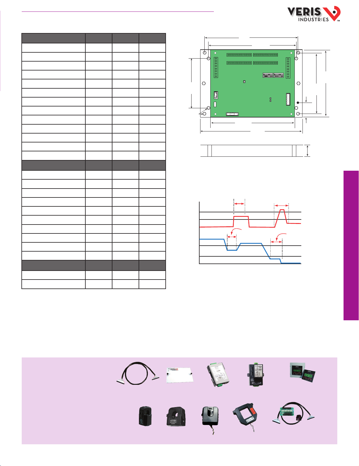
The E3x series monitors the current, voltage, and energy consumption of each
circuit in a panelboard including the main breaker. The accumulated information
can be transmitted through the communications interface. Data updates
occur roughly every two seconds to provide timely preventative maintenance
information. As a circuit approaches the user-congured thresholds, alarm
indicators are triggered, preventing costly downtime from overloaded circuits or
failed loads. (See graph, facing page)
power/energy monitoring
APPLICATIONS
● Load based cost allocation
● Overload protection
● Load management
● Load balancing
● Lighting circuits
NEW
Year
5
SPECIFICATIONS
Inputs:
Input Power 90-277VAC, 50/60 Hz
Accuracy:
Power/Energy IEC 62053-21 Class 1, ANSI C12.1-2008
Volt age ±0.5% of reading 90-277V line-to-neutral
Operation:
Sampling Frequency 2560 Hz
Update Rate 1.8 seconds (both panels)
Outputs:
Typ e Modbus RTU
Connection DIP switch-selectable 2-wire or 4-wire, RS-485
Address DIP switch-selectable address 1 to 247 (in pairs of 2)
Baud Rate DIP switch-selectable 9600, 19200, 38400
Parity DIP switch-selectable NONE, ODD, EVEN
Communication Format 8-data-bits, 1-start-bit, 1-stop-bit
Termination 5-position depluggable connector (TX+ TX- SHIELD TX+/RX+ TX-/RX-)
Terminal Block Torque 4.4 to 5.3 in-lb (0.5 to 0.6 N-m)
Mechanical:
Ribbon Cable Support 4 ft. (0.9 m) ribbon cable ships standard; up to 20 ft. (6 m) at and round c ables available
Environmental:
Operating Temperature Range 0° to 60°C (32° to 140°F) (<95% RH noncondensing)
Storage Temperature Range -40° to 70°C (-4 0° to 158°F)
Altitude of Operation 3000 m
Agency Approvals UL508, EN61010
Warranty
FEATURES
● Revenue Grade measurements
● IEC Class 1 metering accuracy
● Up to 126 panelboards can be monitored on one RS-485 drop...simplies wiring
● Reports volts, amps, power, and energy for each circuit...one product covers the
whole panelboard
● 92 circuits with one product (84 branch circuits, 2 3-phase mains, 2 neutrals)...
saves space
● 3/4”, or 1”, or 18 mm spaced solid-core current sensors...exible installation
● Split-core version has two mounting options (DIN Rail or Snaptrack)...
installation exibility
● 4 user-congurable alarm threshold registers...improved load management
● Built-in ability to set the orientation and numbering of the circuits
● 1/4 amp to 100 amp solid-core monitoring...widest dynamic range
in the industry
● 1, 2, 3 pole breaker support
● Applications for new construction (solid-core version) and retrots
(split-core version)
● Modbus RTU standard
● Modbus TCP over Ethernet available with addition of U013-0012...page 166
● BACnet IP or MS/TP available with addition of E8950...see page 164 (E30Ax84
and E31Axxx not supported)
800.354.8556
+1 503.598.4564
www.veris.com
HQ0001714.C 01132
Page 2
800.354.8556
0A
Ch. 2
Ch. 1
TIME
High High
High Alarm
Latched
Low Alarm
Latched
No Alarm
Latched
Low Low Alarm Latched
High
Low Low
Low
AMPS
+1 503.598.4564
www.veris.com
DATA OUTPUT
Monitoring at Mains E3xA E3xB E3xC
Current per phase
Max. current per phase
Current demand per phase
Max. current demand per phase
Energy (kWh) per phase
Real Power (kW) per phase
Apparent Power (kVA)
Power factor total *
Power factor per phase
Voltage, L-L and average
Voltage, L-N and average
Voltage, L-N and per phase
Frequency (phase A)
Monitoring at Branch Circuit
Current
Max. current
Current demand
Max. current demand
Real power (kW)
Real power (kW) demand
Real power (kW) demand max.
Energy (kWh) per circuit
Power factor
Apparent Power (kVA)
Modbus Alarms
Voltage over/under
Current over/under
* Based on a 3-phase breaker rotation.
n n n
n n n
n n n
n n n
n n
n n
n n
n n
n n
n n
n n
n n
n n
n n n
n n n
n n n
n n n
n
n
n
n
n
n
n n
n n n
DIMENSIONAL DRAWINGS
8.3”
3.9”
(100 mm)
Ø = 0.2”
(5 mm)
(211 mm)
7.3”
(184 mm)
7.9”
(200 mm)
8.9”
(226 mm)
OPERATION EXAMPLE
1.75”
(45 mm)
(122 mm)
5.8”
(146 mm)
4.8”
Height
(Board + Bracket)
1.7” (44 mm)
ACCESSORIES
Ribbon Cables, round or a t (CBLxxx)
E3x cover (AE001)
Modbus TCP Gateway (U013- 0012)
Modbus-to-BACnet Converter (E8950)
Network Display (H8932, H8936)
CTs (E31CT0, E31CT1, E31CT3)
CTs for auxiliary input s (H681x)
Repair kit for E30 (AE006)
HQ0001714.C 01132
power/energy monitoring
CBL022
AE001 U013-0012
E8950
E31CT0 E31CT1
E31CT3
H681x
H8932/H8936
AE006
Page 3

800.354.8556
+1 503.598.4564
www.veris.com
Panelboard Monitoring System – Solid-Core
DIMENSIONAL DRAWINGS
Current Sensor Strips
20.3” (516 mm)
3/4"
option,
21 C Ts
E30
1.3”
(33 mm)
2.0”
(50 mm)
0.4” (10 mm)
opening
slot: 0.25” x 0.5”
(7 x 13mm)
0.75” (19 mm)
on center
1.1”
(28 mm)
0.8”
(20 mm)
APPLICATION/WIRING EXAMPLE
Panel Board 1 Panel Board 2
power/energy monitoring
92 circuits with
one product
E30 Current Sensor Strip
Connection
to auxiliary inputs
To Controller or PC
SOLID-CORE CT SPECIFICATIONS
Voltage Rating 300VAC
Accuracy ±0.5%
Temperature 0° to 60°C
Agency UL508 recognized, EN61010
E30 CURRENT SENSOR STRIP
E30 CURRENT SENSOR STRIP
100A Solid-Core CT
E30 CURRENT SENSOR STRIP
Monitors each circuit
Acquisition Board
RS-485 Modbus:
Up to 63 E30s
in a panelboard
including the
main breaker
E30 Data
Reports volts, amps,
power, and energy
for each circuit
1”
option,
21 C Ts
18 mm
option,
21 C Ts
18 mm
option,
18 C Ts
18 mm
option,
12 C Ts
1.2”
(30 mm)
2.0”
(50 mm)
2.0”
(50 mm)
1.3”
(32 mm)
1.7”
(43 mm)
1.3”
(32 mm)
1.7”
(43 mm)
1.3”
(32 mm)
0.4” (10 mm)
opening
15.7” (399 mm)
0.4” (10 mm)
opening
16.4” (417 mm)
0.4” (10 mm)
opening
12.3” (312 mm)
0.7” (18 mm)
on center
25.0” (635 mm)
0.4” (10 mm)
opening
0.7” (18 mm)
on center
0.7” (18 mm)
on center
slot: 0.25” x 0.5”
(7 x 13mm)
1.0” (26 mm)
on center
21.2”
(0.9 mm)
1.2”
(31 mm)
0.8”
(20 mm)
21.2”
(0.9 mm)
21.2”
(0.9 mm)
ORDERING INFORMATION
Description
E30
A = Advanced
B = Intermediate
C = Basic
Examp le:
E30 A 0 42
Free Configuration tool available from www.veris.com.
Consult factory for additional mounting options.
CT Option
0 = 100A, ¾" spacing
1 = 100A, 1" spacing
2 = 100A, 18 mm spacing
Ribbon Cables
24 = 2 strips of 12 CTs (18 mm only)
36 = 2 strips of 18 CTs (18 mm only)
42 = 2 strips of 21 CTs (¾”, 1”, or 18 mm) with two 4 -ft. at ribbon cables
48 = 4 strips of 12 CTs (18 mm only)
72 = 4 strips of 18 CTs (18 mm only)
84 = 4 strips of 21 CTs (¾”, 1”, or 18 mm) with four 4 -ft. at ribbon cables
# of CTs and
HQ0001714.C 01131
Page 4

800.354.8556
+1 503.598.4564
www.veris.com
Panelboard Monitoring System – Split-Core
DIMENSIONAL DRAWINGS
Adapter Board
1.00”
(26 mm)
E31
E31xY63*
APPLICATION/WIRING DIAGRAM
3
2
1
ORDERING INFORMATION
1
Boards
Description
# of CTs
E31
A = Advanced b oard
B = Interme diate board
C = Basic boa rd
2
CTs (up to 21 CTs per adapter b oard)
E31CT0 Six-pack , 50A CT, 6 ft. (1.8 m) lead
E31CT0R20 Six-pack , 50A CT, 20 ft. (6 m) lead
E31CT1 Six-pack , 100A CT, 6 ft. (1.8 m) lead
E31CT1R20 Six-pack , 100 CT, 20 ft. (6 m) lead
E31CT3 Single CT, 200A C T, 6 ft. (1.8 m) lead
E31CT3R20 Single CT, 200A C T, 20 ft. (6 m) lead
002 = 2 adapter b oards, no CTs, no cable s
004 = 4 adap ter boards, no CTs, no cab les
42 = 2 adapter boa rds, 42 50A CTs, 2 4 ft. round r ibbon cables
84 = 4 adapter b oards, 84 50A CTs, 4 4 ft . round ribbon ca bles
Y63* = 2 adapter boar ds, at ribbon cab les,
pre-as sembled on one brac ket, CTs not included
B
(248 mm)
1.00”
(26 mm)
D
C
B
B
E
D
C
D
C
A
E
E
E31xY63 Boards with Bracket*
9.75”
CTs
A
4.6”
(117 mm)
A
8.75”
(222 mm)
2.75”
(70 mm)
E31CT0 50 Amp
A = 1.0” (26 mm)
B = 0.5” (11 mm)
C = 0.4” (10 mm)
D = 0.9” (23 mm)
E = 1.6” (40 mm)
E31CT1 100 Amp
A = 1.5” (39 mm)
B = 0.8” (20 mm)
C = 0.7” (16 mm)
D = 1.6” (40 mm)
E = 2.1” (53 mm)
E31CT3 200 Amp
A = 1.5” (39 mm)
B = 1.25” (32 mm)
C = 1.25” (32 mm)
D = 2.5” (64 mm)
E = 2.8” (71 mm)
power/energy monitoring
3
Ribbon Cable (order 1 cable pe r adapter board)
CBL022 Round Rib bon Cable, 4 ft. (1.2 m)
CBL033 Round Rib bon Cable, 8 ft. (2.4 m)
CBL023 Round Rib bon Cable, 10 ft. (3 m)
CBL024 Round Rib bon Cable, 20 ft. (6 m)
Ordering Examples:
Option A: For m onitoring 42 or 84 ci rcuits, orde r a pre-made kit fr om Group 1 only
(see Applic ation/Wiri ng Diagram abo ve).
Exampl e: E31x42 or E31x84
Option B: For m onitoring oth er conguratio ns, build your o wn kit by selecti ng from
Groups 1, 2, and 3.
Exampl e kit for an 18-circu it panel retro t:
1 E31A002 - Advance d board, 2 adapte r boards (1 unit)
2 E31CT0 - 50A CT six-pack (3 units)
3 CBL023 - 10 ft. round ribbo n cable (2 units)
800.354.8556
CBL016 Flat Ribbo n Cable, 4 ft. (1.2 m)
CBL018 Flat Ribbo n Cable, 6 ft. (1.8 m)
CBL020 Flat Ribbo n Cable, 10 ft. (3 m)
CBL021 Flat Ribbo n Cable, 20 ft. (6 m)
+1 503.598.4564
SPLIT-CORE CT SPECIFICATIONS
50A Split-Core CT 100A Split-Core CT 200A Split-Core CT
Voltage Rating 300VAC 600VAC 600VAC
Accuracy ±1% ±0.5% ±1%
Temperature 0° to 60°C 0° to 60°C 0° to 60°C
Agency UL508 recognized,
EN61010
www.veris.com
HQ0001714.C 01131
UL508 recognized,
EN61010
UL508 recognized,
EN61010
 Loading...