

Page 1
TM
ENVIRONMENTAL SENSORS
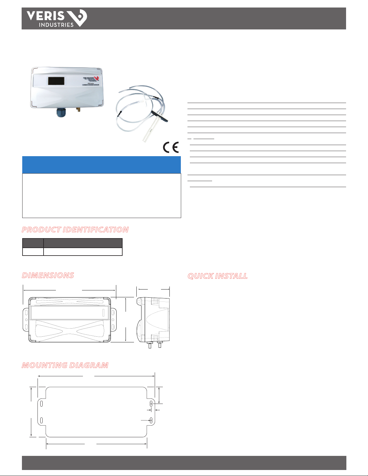
CRLSxx CRLSxx
CRL
AA50
NOTICE
• This product is not intended for life or safety applications.
• Do not install this product in hazardous or classified locations.
• Read and understand the instructions before installing
this product.
• Turn off all power supplying equipment before working on it.
• The installer is responsible for conformance to all applicable codes.
PRODUCT IDENTIFICATION
MODEL DESCRIPTION
CRLSxx CO2 Based Remote Mount Sensor
INSTALLATION GUIDE
Environmental CO2 Remote Mount Sensor
Installer’s Specifications
Input Voltage 20 to 30VDC, 24AC
Analog Output 4-20mA (clipped and capped)/0-5VDC/0-10VDC (selectable)
Sensor Current Draw 100mA max.
Operating Temperature Range 0° to 50°C (32° to 12 2°F)
Operating Humidity Range 0-95% (noncondensing)
Housing Material High impac t ABS plastic
CO2 Transmitter:
Sensor Type Non-dispersive infrared (NDIR), diusion sampling
Output Range 0-2000 ppm or 0 -5000 ppm, user selectable
Accuracy ±30 ppm ±5% of measured value
Repeatability ±20 ppm ±1% of measured value
Response Time <60 seconds for 9 0% step change
when used with supplied 3 ft. sampling tube (AA50)
Relay Contac ts:
1 Form C 1A@30VDC, resistive; 30W max.
EMC Conformance: EN 61000-6-4:2001 Class B, EN 61000-6-1:2001
EMC Test Methods: CISPR 11:2004, IEC 61000-4-2:2001, IEC 61000-4-3:2002, IEC
61000-4-4:2004, IEC 61000-4-5:2001, IEC 61000-4-6:2004, IEC 61000-4-8:2001, IEC
61000-4-11:2004
EMC Special Note: Connect this product to a DC distribution network or an AC/DC power
adaptor with proper surge protection (EN 61000-6-1:2001 specication requirements).
When directly measuring outside air, ensure that the air temperature reaching the sensor
is between 0° and 50°C.
Note: Rough handling and transp ortation may cause a temporary reduction of CO2 sensor
accuracy. With time, the ABC function will tun e the readings back to the correct accuracy range.
The default tuning speed is li mited to 30 ppm per week.
DIMENSIONS
6.7"
(170 mm)
MOUNTING DIAGRAM
6.7"
(175 mm)
3.1"
(78 mm)
5.7"
(144 mm)
3.1"
(78 mm)
0.4" x 0.2"
(11mm x 5mm)
2.4"
(61 mm)
QUICK INSTALL
1. Mark and drill at least two mounting holes for the sensor.
2. Secure the sensor the the mounting surface.
3. Attach the provided pickup tubes, ensuring the supply line is connected to the
front (high) port and the return line is connected to the back (low) port.
4. Wire the device. See the Wiring section for more information.
5. Power the device.
6. Follow Conguration procedure (page 3).
1"
(26 mm)
typ
0.3"
(6 mm)
typ
Z205242-0B PAGE 1 ©2011 Veris Industries USA 800.354.8556 or +1.503.598.4564 / support@veris.com 02113
Alta Labs, Enercep t, Enspector, Hawkeye, Trustat, Veris, and the Veris ‘ V’ logo are trademark s or registered tradema rks of Veris Industries, L.L .C. in the USA and /or other count ries.
Page 2
TM
mA Volt
NC COMM NO
PLUS
ENTER
MINUS
CONFIGURATION
PUSHBUTTONS
V+ CO2-OUT GND
ON
OFF
LOW
ABC
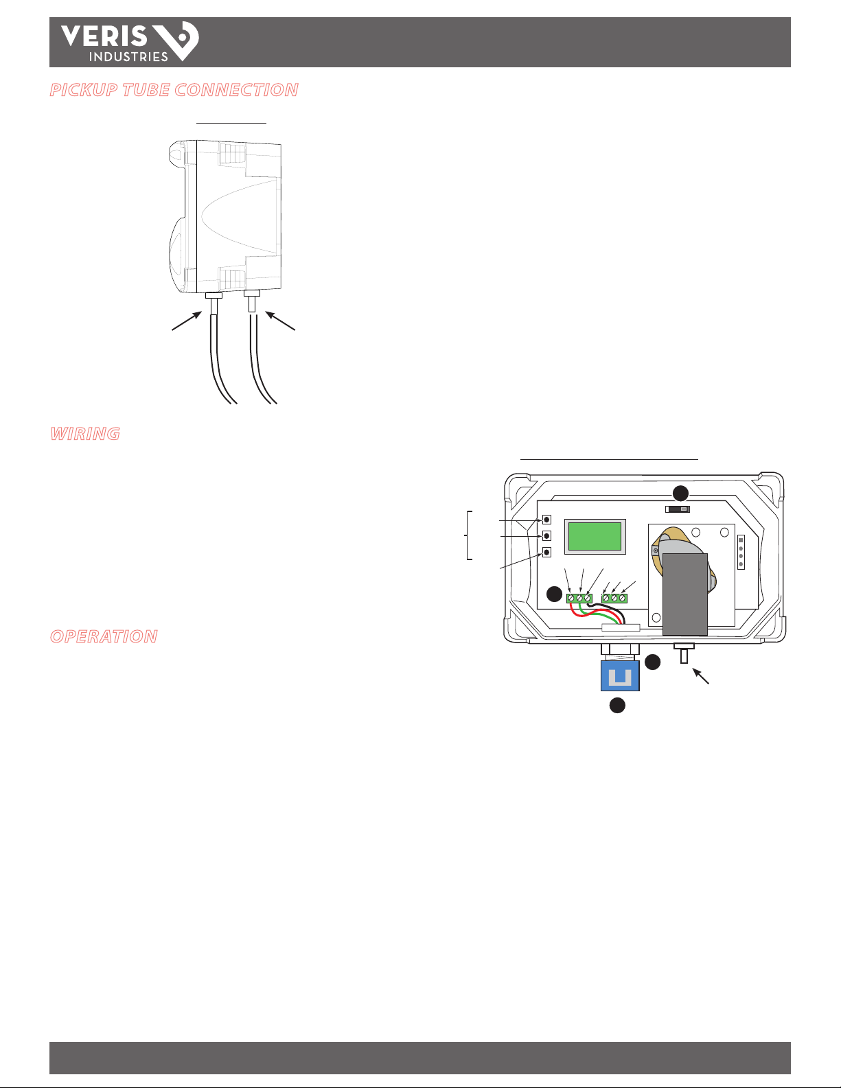
PICKUP TUBE CONNECTION
CRL, Side View
CRLSxx
INSTALLATION GUIDE
Front
Supply (High Port)
Back
Return (Low Port)
WIRING
1. Feed control wire through conduit adapter and grommeted compression tting on
the bottom of the housing.
2. Remove terminal blocks by pulling straight up on the green assemblies. Connect
wires as shown at left, and push terminal blocks back in to black receptacles.
3. Tighten compression tting around control wire until sealed. Snap conduit adapter
onto compression tting. Refer to specications for power requirements and relay
rating.
4. Select mA or Volt output using selector switch.
Front View, with Face Plate Removed
4
2
OPERATION
The CRLSxx remote mount CO2 sensor ensures adequate ventilation using NDIR
technology combined with a self-calibration algorithm. The device comes with a
three-foot length of pickup tubing for easy installation. Output is eld selectable
(4-20mA/0-5VDC/0-10VDC).
To operate the CRL, install onto a vertical mounting surface. Then apply power and
congure (page 3).
3
0.24" (6.1mm)
1
O.D. barb ttings
Z205242-0B PAGE 2 ©2011 Veris Industries USA 800.354.8556 or +1.503.598.4564 / support@veris.com 02113
Alta Labs, Enercep t, Enspector, Hawkeye, Trustat, Veris, and the Veris ‘ V’ logo are trademark s or registered tradema rks of Veris Industries, L.L .C. in the USA and /or other count ries.
Page 3

TM
XX
SA
PM
IT
ENAD
XXX
AM
BDOE
–0
OU
V+
–+
CA
CA
*:00
WN
OU
CRLSxx
INSTALLATION GUIDE
CONFIGURATION
RUN MODE:
100
0
*
CO2 MODEL
*INDICATES RELAY STATUS
P
CO2
CONFIGURATION MODE:
PRESS [ENTER] FOR CONFIGURATION MODE.
PRESS PLUS OR MINUS TO CHANGE SETTING.
SPOT
E
O2C
RANGE 500 TO 1500
50PPM INC REMENT
80 0
DDBA
2CO 010
RANGE 10 TO 500
5 PPM INCREMENT
RGEN
A
CO
2
OPTIONS ARE 2000 OR 5000
X
C
XX +X–
CALIBRATION MODE:
PUSH AND HOLD PLUS AND MINUS FOR 5 SECONDS
TO ENTER MODE. PRESS ARROW TO CHANGE OPTION.
PUSH ENTER FOR N EXT SELECTIO N.
N
E
R
XX
X
DISPLAYS SERIAL NUMBER
X
X
XX
XXX
DISPLAYS MO DEL NUMBER
2
O
OPTIONS ARE YES, NO
L
A
OPTIONS ARE NONE, 0, 400
X
C
X
XLX
G
X–
XSXX+
LI
XXX
?
?
OPTIONS ARE ON, LOW, OFF
SEE NEXT PAGE FOR EXPLANATION
U
T
–1
0
(VOLTAGE MODE ONLY)
OPTIONS: 0-10V OR 0-5V
DEFAULT IS 0-10V
U
T
40
–2
(mA MODE ONLY)
m
TP
TP
A
RI
KO
G
5
Unit will automatically retu rn to run mode
when calibration is complete.
NOTE: This pr oduct is fac tory calibrat ed. The typical CO2
sensor c alibration inter val is 5 years, depe nding on specic s ite
install ation factor s. As of the date of this d ocument, complia nce
with ANSI/ASHR AE 62-2001 requi res minimum on-si te accuracy
verica tion intervals o f 6 months, or per the bu ilding operatio n and
maintenance manual. Accuracy verication should be perfo rmed
using eith er a comparison to a kn own reference or a CO2 gas
calibra tion kit available f rom Veris Industr ies (model AA01).
WARNING: CO2 sensor calibration requires gas calibration kit.
Perfor ming calibrati on without gas kit w ill cause errone ous
readings. Consult factory for calibration kit.
Z205242-0B PAGE 3 ©2011 Veris Industries USA 800.354.8556 or +1.503.598.4564 / support@veris.com 02113
Alta Labs, Enercep t, Enspector, Hawkeye, Trustat, Veris, and the Veris ‘ V’ logo are trademark s or registered tradema rks of Veris Industries, L.L .C. in the USA and /or other count ries.
Page 4

TM
CALIBRATION PROCESS
1. Connect hose to plastic port located on sensing module.
2. Start owing nitrogen gas (0 ppm CO2 only).
3. Enter Calibration mode as described on page 3.
CRLSxx
INSTALLATION GUIDE
STEP 1
Calibration Port
Regulator
Valve
Connect hose here
ABC CALIBRATION ALGORITHM
NITROGEN
GAS
STEP 2
Flow Nitrogen.
OUTPUT SCALING
STEP 3
Calibrate for 5 min. Unit will return to
working display when finished.
ABC (Automatic Baseline Calibration) is a patented self-calibration feature that
automatically adjusts the CO2 sensor to compensate for drift. When ABC is enabled,
the lowest reading within every 24-hour period is recorded and analyzed over
a running 7 day or 28-day period. If a statistically signicant amount of drift is
detected, an automatic correction factor is applied. This enables the sensor to operate
within specications for the 5-year calibration interval.
NOTE: After changing the ABC settings, the unit will need to be power cycled for the
changes to take eect.
Output scaling: 0-2000ppm
CO2 ppm 0-5 Volt
Output
Outside 300-500 0.75 to 1.25 1.5 to 2.5 6.4 to 8
Over Ventilated Under 600 under 1.5 Under 3 Under 8.8
Ideal Ventilation 600-900 1.5 to 2.25 3 to 4.5 8.8 to 11.2
Under Ventilated Over 900 over 2.25 Over 4.5 Ov er 11.2
0-10 Volt
Output
Output
mA
Z205242-0B PAGE 4 ©2011 Veris Industries USA 800.354.8556 or +1.503.598.4564 / support@veris.com 02113
Alta Labs, Enercep t, Enspector, Hawkeye, Trustat, Veris, and the Veris ‘ V’ logo are trademark s or registered tradema rks of Veris Industries, L.L .C. in the USA and /or other count ries.
 Loading...