

Page 1
TM
(61 mm)
CD SerieS CD SerieS
CDE
CDL
NOTICE
• This product is not intended for life or safety applications.
• Do not install this product in hazardous or classified locations.
• Read and understand the instructions before installing
this product.
• Turn off all power supplying equipment before working on it.
• The installer is responsible for conformance to all applicable codes.
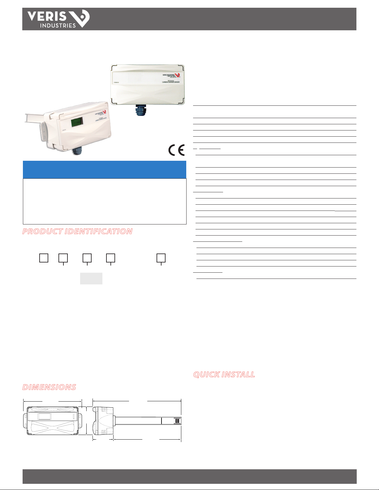
PRODUCT IDENTIFICATION
DELUXE MODEL:
ENVIRONMENTAL SENSORS
RH Option
CDL
S
H = RH2%
X = NO RH
ECONOMY MODEL:
CDE (no options)
Temp
T = Temp
X = No Temp
(Stop Here)
Sensor Type
A = Transmitte r
B = 100R Platinu m, RTD
C = 1k Platinum, RTD
D = 10k T2, RTD, Ther mistor
E = 2.2k, Ther mistor
F = 3k, Therm istor
G = 10k CPC, Ther mistor
H = 10k T3, Thermi stor
J = 10k Dale, Ther mistor
K = 10k w/11k shunt, Thermist or
M = 20k NTC, Ther mistor
N = 1800 ohm, Ther mistor
R = 10k US, Thermis tor
S = 10k 3A221, Thermis tor
T = 100k, The rmistor
U = 20k “D”, Thermis tor
Optional Cal Cert.
Blank = None
1 = 1 pt Temp Cert
2 = 2 pt Temp Cert
INSTALLATION GUIDE
Duct Mounted Environmental CO2 Sensors
Installer’s Specifications
Input Voltage 20 to 30VDC, 24AC
Analog Output CDE models: 4-20mA (clippe d & capped)/0-10VDC (selectable)
CDL models: 4-20mA (clipped & capped)/0-5VDC /0-10VDC (selectable)
Sensor Current Draw 100mA Maximum
Operating Temperature Range 0° to 50°C (32° to 122°F)
Operating Humidity Range 0-95% (noncondensing)
Housing Material High impac t ABS plastic
CO2 Transmitter:
Sensor Type Non-dispersive infrared (NDIR), diusion sampling
Output Range 0-2000 ppm or 0 -5000 ppm, user selectable on CDL models,
0-2000 ppm on CDE mo dels
Accuracy ±30 ppm ±2% of measured value*
Repeatability ±20 ppm ±1% of measured value
Response Time <60 seconds for 90% step c hange
RH Transmitter**:
HS Sensor Digitally pr oled thin-lm capacitive (32-bit mathematics); U.S. Patent 5,844,138
Accuracy ±2% from 10 to 80% RH @ 25°C; Multi-point calibration NIST
Hysteresis 1.5% typical
Linearity Included in Accuracy spec.
Stability ±1% @ 20°C (68°F) annually, for two years
Output Range 0 to 100% RH
Temperature Coecient ±0.1% RH/°C above or below 25°C (typical)
Temperature (Transmitter)**:
Sensor Type Solid-state, integrated circuit
Accuracy ±0.5°C (±1°F) typical
Resolution 0.1°C (0.2°F)
Output Range 10° to 35°C (50° to 95°F)
Relay Contacts**:
1 Form C 1A@30VDC, resistive; 30W max.
Specied accuracy with 24VDC supplied power with rising humid ity. RTD/Thermistors in wall
packages are not compensated for internal heating of product.
EMC Conformance: EN 61000- 6-3:2001 (Amended by A11:2004) Class B, EN 61000- 6-1:2001
EMC Test Methods: CISPR 22:2006, IEC 61000-4-2:2001, IEC 61000-4 -3:2006, IEC 61000-4- 4:2004,
IEC 61000-4-6:2006, IEC 61000-4-8:2001, IEC 61000-4-11:2004
EMC Special Note: Connect this produc t to a DC distribution network or an AC/DC powe r adaptor
with proper Surge protection (EN 61000-6-1:2001 specication requirements).
* Measured at NTP
** Not available on CDE
Note: Rough handling and transp ortation may cause a temporary reduction of CO2 sensor
accuracy. With time, the ABC function will tun e the readings back to the correct accuracy range.
The default tuning speed is li mited to 30 ppm per week.
QUICK INSTALL
DIMENSIONS
6.7"
(170 mm)
3.1"
(78 mm)
2.4"
Z204900-0K PAGE 1 ©2011 Veris Industries USA 800.354.8556 or +1.503.598.4564 / support@veris.com 06114
Alta Labs, Enercep t, Enspector, Hawkeye, Trustat, Veris, and the Veris ‘ V’ logo are trademark s or registered tradema rks of Veris Industries, L.L .C. in the USA and/or othe r countries.
10.2"
(258 mm)
7.8"
(97 mm)
1. Using the mounting diagram on page 2, or using the housing as a template, mark
and drill the four mounting holes on the duct. The centerline through the housing
must be parallel to the air ow through the duct.
2. Rotate the duct probe so that its widest sur face is perpendicular to the air ow in
the duct.
3. Insert the probe and secure the sensor to the duct with the sheet metal screws
provided, making sure that the provided gasket material is compressed between
the sensor housing and the air duct.
4. Wiring. See wiring diagrams on next page.
Page 2
TM
would not be covered under the factory warranty.
(78 mm)
Rotate the duct probe
so the channeled side is
perpendicular to the
air flow of the duct
Air Flow
Air Flow
CD SERIES
INSTALLATION GUIDE
OPERATION
CD series duct mount CO2 sensors measure the levels of CO2, RH (if equipped), and
temperature (if equipped) of air inside a duct. The CO2 sensor operates within
accuracy specications for an interval of 5 years and can be eld calibrated. The
temperature element is warranted to meet accuracy specications for a period of
5 years. RH equipped models feature a replaceable HS Series humidity element
that is warranted to meet accuracy specications for a period of 1 year. To maintain
accuracy, all vents must remain clear and free of dust, debris, etc.
INSTALLATION
Observe handling precautions for static sensitive
devices to avoid damage to the circuitry which
1. Choose a location to mount the sensor. The centerline of the housing must be
parallel to the direction of air ow in the duct.
2. Use the mounting diagram to drill the four holes in the duct for securing the
sensor.
6.7"
(175 mm)
1" diameter
3.1"
C
L
2.2"
(56 mm)
0.4" x .0.2"
(typical)
1"
(26 mm)
typ
0.3"
(6 mm)
typ
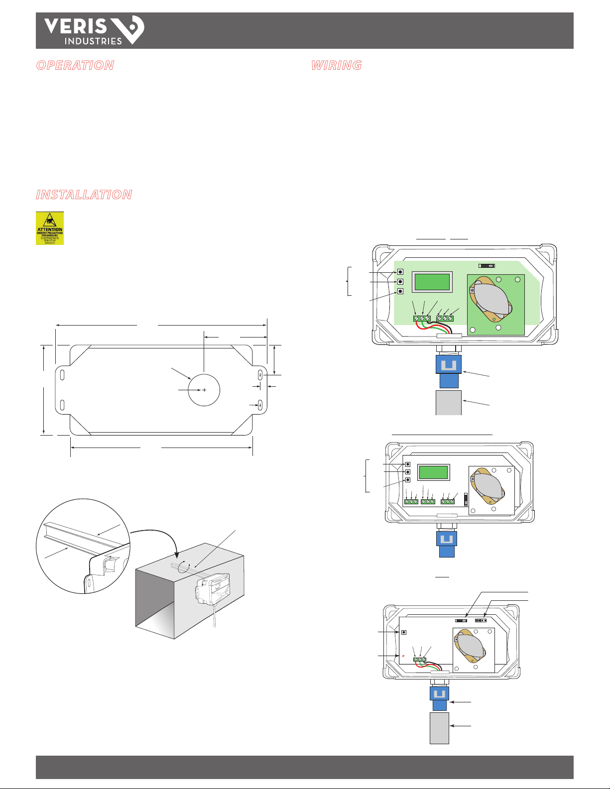
WIRING
1. Feed control wire through conduit adapter and grommeted compression tting on
the bottom of the housing.
2. Remove terminal blocks by pulling straight up on the green assemblies.
3. Connect wires as shown and push terminal blocks back in to black receptacles.
4. Tighten compression t ting around control wire until sealed.
5. Snap conduit adapter onto compression tting.
6. Refer to specications for power requirements and relay rating.
7. Select mA or Volt output using selector switch.
CDL - CO2 Only
Configuration
Pushbuttons
PLUS
ENTER
MINUS
V+ CO2-OUT GND
NC COMM NO
mA Volt
1/2” NPT MALE CONDUIT ADAPTER
1/2” NPT FEMALE COUPLER
5.7"
(144 mm)
3. Insert the probe into the hole. Rotate the housing so that the widest surface is
perpendicular to the air ow.
4. Attach the sensor to the duct using the sheet metal screws provided. Make sure
that the gasket on the back of the housing is compressed between the housing
and the duct for a secure t.
5. Wire the device. See Wiring section.
6. Congure the system using the menu (CDL only; see Conguration section).
7. Calibrate using 0 ppm CO2 gas (see Calibration section).
CONFIGURATION
PUSHBUTTONS
Calibration
Pushbutton
CDL with Temp & RH Options
PLUS
ENTER
RH OUT
V+
MINUS
CO2 OUT
TEMP OUT/RTD
RTD
GND
CDE
V+ CO2-OUT GND
LED
NC COMM NO
mA
Volt
mA Volt
mA/Volt Selection Switch
ABC Jumper
Conduit Adapter
1/2” NPT male/female
Z204900-0K PAGE 2 ©2011 Veris Industries USA 800.354.8556 or +1.503.598.4564 / support@veris.com 06114
Alta Labs, Enercep t, Enspector, Hawkeye, Trustat, Veris, and the Veris ‘ V’ logo are trademark s or registered tradema rks of Veris Industries, L.L .C. in the USA and/or othe r countries.
Page 3

TM
XX
SA
IT
ENAD
XXX
AM
BDOE
–+
–0
OU
V+
CX
OE
PM
PM00150P
O.O
%R H
PM
˚F
XX
OU
RX
.X
–+
CA
*:00
WN
CA
CD SERIES
INSTALLATION GUIDE
CONFIGURATION: CDL MODELS
RUN MODE:
100
*
*INDICATES RELAY STATUS
0
7
XX.
X
CO2/R H/T COM BO MOD EL
TOGGLE %RH AND DEGREES
0
CO2 ONLY MODEL
CO2/R H COMBO M ODEL
0010
.
0
CO2/T COMBO M ODEL
0010
P
CO2
P
PPM
X
CONFIGURATION MODE:
PRESS [ENTER] FOR CONFIGURATION MODE.
PRESS PLUS OR MINUS TO CHANGE SETTING.
SPOT
E
O2C
RANGE 500 TO 1500
50PPM INC REMENT
80 0
DDBA
2CO 010
RANGE 10 TO 500
5 PPM INCREMENT
RGEN
A
CO
2
OPTIONS ARE 2000 OR 5000
X
C
XX +X–
OPTIONS ARE ON, LOW, OFF
SEE NEXT PAGE FOR EXPLANATION
CALIBRATION MODE:
PUSH AND HOLD PLUS AND MINUS FOR 5 SECONDS
TO ENTER MODE. PRESS ARROW TO CHANGE OPTION.
N
PUSH ENTER FOR N EXT SELECTIO N.
E
R
XX
X
DISPLAYS SERIAL NUMBER
X
X
XX
XXX
DISPLAYS MO DEL NUMBER
F.XS
F
X
LI
XXX
T
º
RANGE IS -5 TO 5ºC
0.1ºC INCREMENT
(CO2/temp combo models)
F
FO
%
S
TE
HX
RANGE -10 TO 10%
0.1% INCREMENT
(CO2/RH combo models)
U
N
SIXT
º
(TEMP MODELS ONLY)
OPTIONS ARE ºF or ºC
U
T
–1
0
(VOLTAGE MODE ONLY)
OPTIONS: 0-10V OR 0-5V
DEFAULT IS 0-10V
U
T
40
–2
(mA MODE ONLY)
m
TP
TP
A
2
O
OPTIONS ARE YES, NO
L
A
OPTIONS ARE NONE, 0, 400
RI
C
X
XLX
G
X–
XSXX+
KO
?
?
G
5
Unit will automatically retu rn to run mode
when calibration is complete.
NOTE: This product is factory calibrated. The typical CO2 sensor
calibration interval is 5 years , depending on specic site
installation factors. A s of the date of this document, compliance
with ANSI/ASHRAE 62-2001 requires minimum on-site accuracy
verication intervals of 6 months or per the building operation
and maintenance manual. Verif y accuracy using a comparison
to a known reference or the CO2 gas calibration kit available
from Veris Industries as AA01.
Z204900-0K PAGE 3 ©2011 Veris Industries USA 800.354.8556 or +1.503.598.4564 / support@veris.com 06114
Alta Labs, Enercep t, Enspector, Hawkeye, Trustat, Veris, and the Veris ‘ V’ logo are trademark s or registered tradema rks of Veris Industries, L.L .C. in the USA and/or othe r countries.
WARNING: CO2 sensor calibration requires gas calibration kit.
Performing calibration with out gas kit or at an incorrect gas
ow rate will cause erroneous readings.
Page 4

TM
ABC Settings (CWE only)
CD SERIES
INSTALLATION GUIDE
ABC CALIBRATION ALGORITHM
ABC (Automatic Baseline Calibration) is a patented self-calibration feature that
automatically adjusts the CO2 sensor to compensate for drift. When ABC is enabled,
the sensor records the lowest reading within every 24-hour interval and compares
these values over a running 7-day or 28-day period. If a statistically signicant
amount of drift is detected, the ABC applies an automatic correction factor. This
enables the sensor to operate within specications for the 5-year calibration interval.
ON POSITION. Recommended Setting. Use the ON setting for applications where the
building is unoccupied within a 24-hour timeframe.
LOW POSITION. Use the LOW setting for buildings occupied 24 hours a day.
OFF POSITION. Not Recommended.
NOTE: After changing the ABC setti ngs, power cycle the unit for changes to take eect.
To set the ABC mode for CDL models, refer to the Conguration section on page 3.
To set the ABC mode for CDE models, position the ABC jumper as shown:
ON LOW
ON
LOW
OFF
ON
LOW
OFF
OFF
ON
LOW
OFF
CDL MODELS ONLY
CDL versions have optional RH and temperature sensors.
Observe handling precautions for static sensitive
devices to avoid damage to the circuitry which
would not be covered under the factory warranty.
To Replace Humidity Sensor:
1. Power down unit
2. Remove CDL from duct to
access probe tip.
3. Open tip of duct probe
4. Slide old RH sensor o pins
5. Slide new RH sensor onto pins.
6. Re-install CDL in duc t and re-secure with screws provided.
7. Power unit back on
Lift to open
tip of probe
Pins
HS Sensor
OUTPUT SCALING
Output scaling: 0-2000 ppm
CO2 ppm 0-5 Volt
Output
Outside 300-500 0.75 to 1.25 1.5 to 2.5 6.4 to 8
Over Ventilated Under 600 under 1.5 Under 3 Under 8.8
Ideal Ventilation 600-900 1.5 to 2.25 3 to 4.5 8.8 to 11.2
Under Ventilated Over 900 over 2.25 Over 4.5 Ov er 11.2
0-10 Volt
Output
mA
Output
Z204900-0K PAGE 4 ©2011 Veris Industries USA 800.354.8556 or +1.503.598.4564 / support@veris.com 06114
Alta Labs, Enercep t, Enspector, Hawkeye, Trustat, Veris, and the Veris ‘ V’ logo are trademark s or registered tradema rks of Veris Industries, L.L .C. in the USA and/or othe r countries.
Page 5

TM
CD SERIES
INSTALLATION GUIDE
CALIBRATION PROCESS: CDL MODELS
1. Remove cover and connect gas cylinder hose to the plastic port located on sensing
module. Note: only connect one sensor to the calibration gas cylinder at a time.
Connect hose here
2. Start owing nitrogen gas (0 ppm CO2). Use a ow rate of 0.3 to 0.5 liter/minute.
Regulator
Valve
NITROGEN
GAS
CALIBRATION PROCESS: CDE MODELS
1. Remove cover and connect gas cylinder hose to the plastic port located on sensing
module. Note: only connect one sensor to the calibration gas cylinder at a time.
Connect hose here
2. Start owing nitrogen gas (0 ppm CO2). Use a ow rate of 0.3 to 0.5 liter/minute.
Regulator
Valve
NITROGEN
GAS
3. Calibrate for 5 min. Unit will return to working display when nished.
4. When unit returns to working display, remove hose from calibration port and
enter Calibration mode as described on page 3.
3. Push and hold down calibration button until the LED illuminates.
Push and
hold down
calibration
button
Green L ED
4. Continue owing gas through the sensor until the LED is o. Estimated calibration
time is 5 minutes. Remove hose from calibration port when complete.
For more complete calibration instructions using the
AA01 Calibration Kit, see the AA01 Installation Guide.
Z204900-0K PAGE 5 ©2011 Veris Industries USA 800.354.8556 or +1.503.598.4564 / support@veris.com 06114
Alta Labs, Enercep t, Enspector, Hawkeye, Trustat, Veris, and the Veris ‘ V’ logo are trademark s or registered tradema rks of Veris Industries, L.L .C. in the USA and/or othe r countries.
 Loading...