


i
PRISM 3111/3112 T1 / FT1 CSU / DSU


 ®
®
34-00242 November 1998

ii |
|
Copyright |
©1998 TXPORT. All rights reserved. No part of this publication may be reproduced, transmitted, tran- |
|
scribed, stored in a retrieval system, or translated into any language in any form by any means without |
|
the written permission of TXPORT. |
|
Reorder # 34-00242 |
|
5t h Edition, November 1998 |
|
TXPORT shall not be liable for errors contained herein or for incidental or consequential damages in |
|
connection with the furnishing, performance, or use of this material. TXPORT reserves the right to |
|
revise this publication from time to time and make changes in content without obligation to notify any |
|
person of such revision changes. |
|
Contents of this publication may be preliminary and/or may be changed at any time without notice and |
|
shall not be regarded as a warranty. |
Documentation |
TXPORT makes no representation or warranties of any kind whatsoever with respect to the contents |
Disclaimer |
hereof and specifically disclaims any implied warranties of merchantability or fitness for any particular |
|
purpose. |
Trademarks |
IBM is a registered trademark of International Business Machines, Inc. |
|
PROCOMM PLUS is a registered trademark of DATASTORM TECHNOLOGIES, INC. |
Acknowledgment |
The software used in the SNMP function of this product contains material derived from the following |
|
source: |
|
Copyright © 1989 by the Regents of the University of California. All rights reserved. |
|
Redistributions in binary form must reproduce the above copyright notice, this list of conditions, and |
|
the following disclaimer in the documentation and/or other materials provided with the distribution. |
|
All advertising materials mentioning features or use of this software must display the following |
|
acknowledgment: |
|
This product includes software developed by the University of California, Berkeley and its contribu- |
|
tors. |
|
Neither the name of the University nor the names of its contributors may be used to endorse or |
|
promote products derived from this software without specific prior written permission. |
|
This software is provided by the regents and contributors ‘as is’ and any express or implied warranties, |
|
including, but not limited to, the implied warranties of merchantability and fitness for a particular pur- |
|
pose are disclaimed. In no event shall the regents or contributors be liable for any direct, indirect, inci- |
|
dental, special, exemplary, or consequential damages (including, but not limited to, procurement of |
|
substitute goods or services; loss of use, data, or profits; or business interruption) however caused and |
|
on any theory of liability, whether in contract, strict liability, or tort (including negligence or otherwise) |
|
arising in any way out of the use of this software, even if advised of the possibility of such damage. |
FCC Requirements |
Changes or modifications to this unit not expressly approved by the party responsible for |
|
compliance could void the user’s authority to operate the equipment. |
|
This device complies with Part 15 of the FCC rules. Operation is subject to the following two |
|
conditions: |
1This device may not cause harmful interference.
2This device must accept any interference received, including interference that may cause undesired operation.
This equipment has been tested and found to comply with the limits for a Class A digital device, pursuant to Part 15 of FCC Rules. These limits are designed to provide reasonable protection against harmful interference when the equipment is operated in a commercial environment. This equipment generates, uses, and can radiate radio frequency energy and if not installed and used in accordance with the instruction manual, may cause harmful interference to radio communications. Operation of this equipment in a residential area is likely to cause harmful interference. The user will be required to correct the interference at his own expense.

iii
Shielded cables must be used with this unit to ensure compliance with the Class A FCC limits.
This equipment complies with Part 68 of the FCC Rules. On the rear or bottom of this unit is a label that contains the FCC registration number and other information. If requested, provide this information to the telephone company.
1All direct connections to T1 lines must be made using standard plugs and jacks (compliant with Part 68). The following table presents a list of applicable registration jack USOCs, facility interface codes (FIC), and service order codes (SOC). These are required when ordering service from the telco.
|
Port ID |
REN/SOC |
FIC |
USOC |
1.544 |
Mbps (SF) |
6.0N |
04DU9 -BN |
RJ-48C |
1.544 |
Mbps (SF) (B8ZS) |
|
04DU9-DN |
|
1.544 |
Mbps (ESF) |
|
04DU9-IKN |
|
1.544 |
Mbps (ESF) (B8ZS) |
|
04DU9-ISN |
|
|
|
|
|
|
Canadian Emissions
Requirements
2If the unit appears to be malfunctioning, it should be disconnected from the T1 lines until the source of trouble is determined to be your equipment or the telephone line. If your equipment needs repair, it should not be reconnected until it is repaired.
3The unit has been designed to prevent harm to the T1 network. If the telephone company finds that the equipment is exceeding tolerable parameters, it can temporarily disconnect service. In this case, the telephone company will give you advance notice, if possible.
4Under FCC rules, no customer is authorized to repair this equipment, regardless of warranty status.
5If the telephone company alters its equipment in a manner that will affect the use of this device, it must give you advance warning so that you can have the opportunity for uninterrupted service. You will be advised of your right to file a complaint with the FCC.
6The attached affidavit must be completed by the installer.
7In the event of equipment malfunction, all repairs should be performed by our company or an authorized agent. It is the responsibility of users requiring service to report the need for service to our company or to one of our authorized agents.
This digital apparatus does not exceed the Class A limits for radio noise emissions from digital apparatus set out in the Radio Interference Regulations of the Canadian Department of Communications.
For the DC powered units only, end users should use existing battery sources or a CSA certified power supply.
|
Le présent appareil numérique n’émet pas de bruits radioélectriques dépassant les limites applicables |
|
aux appareils numériques (de la class A) prescrites dans le Règlement sur le brouillage radioélectrique |
|
edicté par le ministère des Communications du Canada. |
Hardware Warranty |
TXPORT warrants its hardware products to be free from defects in workmanship and materials, under |
|
normal use and service, for five years from the date of purchase from TXPORT or its Authorized |
|
Reseller: |
|
If a product does not operate as warranted above during the applicable warranty period, TXPORT shall, |
|
at its option and expense, repair the defective product or part, deliver to Customer an equivalent prod- |
|
uct or part to replace the defective item, or refund to Customer the purchase price paid for the defective |
|
product. All products that are replaced will become the property of TXPORT. Replacement products |
|
may be new or reconditioned. Any replaced or repaired product or part has a ninety (90) day warranty |
|
or the remainder of the initial warranty period, whichever is longer. |
|
TXPORT shall not be responsible for any software, firmware, information, or memory data of Cus- |
|
tomer contained in, stored on, or integrated with any products returned to TXPORT for repair, whether |
|
under warranty or not. |
Software Warranty |
TXPORT warrants that the software programs licensed from it will perform in substantial conformance |
|
to the program specifications for a period of ninety (90) days from the date of purchase from TXPORT |
iv
Standard Warranty
Service
or its Authorized Reseller. TXPORT warrants the media containing software against failure during the warranty period. No updates are provided. TXPORT's sole obligation with respect to this express warranty shall be (at TXPORT's discretion) to refund the purchase price paid by Customer for any defective software products, or to replace any defective media with software which substantially conforms to TXPORT's applicable published specifications. Customer assumes responsibility for the selection of the appropriate applications program and associated reference materials. TXPORT makes no warranty or representation that its software products will work in combination with any hardware or applications software products provided by third parties, that the operation of the software products will be uninterrupted or error free, or that all defects in the software products will be corrected. For any third party products listed in the TXPORT software product documentation or specifications as being compatible, TXPORT will make reasonable efforts to provide compatibility, except where the non-compatibility is caused by a bug or defect in the third party's product.
Standard warranty service for hardware products may be obtained by delivering the defective product, accompanied by a copy of the dated proof of purchase, to TXPORT's Corporate Service Center or to an Authorized TXPORT Service Center during the applicable warranty period. Standard warranty service for software products may be obtained by telephoning TXPORT's Corporate Service Center or an Authorized TXPORT Service Center, within the warranty period. Products returned to TXPORT's Corporate Service Center must be pre-authorized by TXPORT with a Return Material Authorization (RMA) number marked on the outside of the package, and sent prepaid, insured, and packaged appropriately for safe shipment. The repaired or replaced item will be shipped to Customer, at TXPORT's expense, not later than thirty (30) days after receipt of the defective product by TXPORT.
Warranties Exclusive |
If a TXPORT product does not operate as warranted above, customer’s sole remedy for breach of that |
|
warranty shall be repair, replacement, or refund of the purchase price paid, at TXPORT’s option. To the |
|
full extent allowed by law, the foregoing warranties and remedies are exclusive and are in lieu of all |
|
other warranties, terms, or conditions, express or implied, either in fact or by operation of law, statutory |
|
or otherwise, including warranties, terms, or conditions of merchantability, fitness for a particular pur- |
|
pose, and satisfactory quality. TXPORT neither assumes nor authorizes any other person to assume for |
|
it any other liability in connection with the sale, installation, maintenance or use of its products. |
|
TXPORT shall not be liable under this warranty if its testing and examination disclose that the alleged |
|
defect in the product does not exist or was caused by customer’s or any third person’s misuse, neglect, |
|
improper installation or testing, unauthorized attempts to repair or modify, or any other cause beyond |
|
the range of the intended use, or by accident, fire, lightning, or other hazard. |
Limitation of Liability |
To the full extent allowed by law TXPORT also excludes for itself and its suppliers any liability, |
|
whether based in contract or tort (including negligence), for incidental, consequential, indirect, special, |
|
or punitive damages of any kind, or for loss of revenue or profits, loss of business, loss of information |
|
or data, or other financial loss arising out of or in connection with the sale, installation, maintenance, |
|
use, performance, failure, or interruption of its products, even if TXPORT or its authorized reseller has |
|
been advised of the possibility of such damages, and limits its liability to repair, replacement, or refund |
|
of the purchase price paid, at TXPORT’s option. this disclaimer of liability for damages will not be |
|
affected if any remedy provided herein shall fail of its essential purpose. |
|
Some countries, states, or provinces do not allow the exclusion or limitation of implied warranties or |
|
the limitation of incidental or consequential damages for certain products supplied to consumers, so the |
|
above limitations and exclusions may be limited in their application to you. This warranty gives you |
|
specific legal rights which may vary depending on local law. |
Governing Law |
This Limited Warranty shall be governed by the laws of the state of Alabama. |
|
TXPORT, Inc., 127 Jetplex Circle, Madison, AL 35758 (256) 772-3770 |
v
Table of Contents
Front Matter
Copyright . . . . . . . . . . . . . . . . . . . . . . . . . . . . . . . . . . . ii Documentation Disclaimer . . . . . . . . . . . . . . . . . . . . . ii Trademarks . . . . . . . . . . . . . . . . . . . . . . . . . . . . . . . . . ii Acknowledgment. . . . . . . . . . . . . . . . . . . . . . . . . . . . . ii FCC Requirements . . . . . . . . . . . . . . . . . . . . . . . . . . . ii Canadian Emissions Requirements . . . . . . . . . . . . . . . iii Hardware Warranty . . . . . . . . . . . . . . . . . . . . . . . . . . . iii Software Warranty. . . . . . . . . . . . . . . . . . . . . . . . . . . . iii Standard Warranty Service . . . . . . . . . . . . . . . . . . . . . iv Warranties Exclusive . . . . . . . . . . . . . . . . . . . . . . . . . . iv Limitation of Liability . . . . . . . . . . . . . . . . . . . . . . . . . iv Governing Law . . . . . . . . . . . . . . . . . . . . . . . . . . . . . . iv
About This Guide
What is a reference manual . . . . . . . . . . . . . . . . . . . . . .1 Where do I go for information. . . . . . . . . . . . . . . . . . . .1 Conventions . . . . . . . . . . . . . . . . . . . . . . . . . . . . . . . . . .2
1 General
Features . . . . . . . . . . . . . . . . . . . . . . . . . . . . . . . . . . . . .4
Specifications. . . . . . . . . . . . . . . . . . . . . . . . . . . . . . . . .4
Network Interface . . . . . . . . . . . . . . . . . . . . . . . . .4
Equipment Interface . . . . . . . . . . . . . . . . . . . . . . . .5
Management Interfaces . . . . . . . . . . . . . . . . . . . . .5
Ethernet (optional) . . . . . . . . . . . . . . . . . . . . .5
Token Ring (optional) . . . . . . . . . . . . . . . . . .5
SLIP Port . . . . . . . . . . . . . . . . . . . . . . . . . . . .5
Supervisory Port . . . . . . . . . . . . . . . . . . . . . . .5
T1 DTE (optional) . . . . . . . . . . . . . . . . . . . . . .5
Dial Backup. . . . . . . . . . . . . . . . . . . . . . . . . . .6
Diagnostics . . . . . . . . . . . . . . . . . . . . . . . . . . . . . . .6
Alarms . . . . . . . . . . . . . . . . . . . . . . . . . . . . . . . . . .6
Power . . . . . . . . . . . . . . . . . . . . . . . . . . . . . . . . . . .6
Mechanical . . . . . . . . . . . . . . . . . . . . . . . . . . . . . . .6
Environmental . . . . . . . . . . . . . . . . . . . . . . . . . . . .6
Standards . . . . . . . . . . . . . . . . . . . . . . . . . . . . . . . .6
Industry Listings . . . . . . . . . . . . . . . . . . . . . . . . . .7
2 Installation
Unpacking and Inspection . . . . . . . . . . . . . . . . . . . . . .9
Supplied Materials . . . . . . . . . . . . . . . . . . . . . . . . . . . . .9
Port Connections . . . . . . . . . . . . . . . . . . . . . . . . . . . . .10
LAN . . . . . . . . . . . . . . . . . . . . . . . . . . . . . . . . . . .10
Ethernet . . . . . . . . . . . . . . . . . . . . . . . . . . . . .10
Token Ring . . . . . . . . . . . . . . . . . . . . . . . . . .10
SLIP . . . . . . . . . . . . . . . . . . . . . . . . . . . . . . . . . . . 11
SUPV . . . . . . . . . . . . . . . . . . . . . . . . . . . . . . . . . . 11
T1 DTE . . . . . . . . . . . . . . . . . . . . . . . . . . . . . . . . 12
NET . . . . . . . . . . . . . . . . . . . . . . . . . . . . . . . . . . . 12
DBU . . . . . . . . . . . . . . . . . . . . . . . . . . . . . . . . . . . 13
Data Port Connections . . . . . . . . . . . . . . . . . . . . . 14
Power Connection . . . . . . . . . . . . . . . . . . . . . . . . 14
AC Power . . . . . . . . . . . . . . . . . . . . . . . . . . . 14
DC Power . . . . . . . . . . . . . . . . . . . . . . . . . . . 15
Power Failure . . . . . . . . . . . . . . . . . . . . . . . . . . . . 15
DIP Switch Settings . . . . . . . . . . . . . . . . . . . . . . . . . . 15
Switch S1 . . . . . . . . . . . . . . . . . . . . . . . . . . . . . . 15
Boot Mode . . . . . . . . . . . . . . . . . . . . . . . . . . 15
SUPV Port Bit Rate . . . . . . . . . . . . . . . . . . 16
SLIP Port Bit Rate . . . . . . . . . . . . . . . . . . . 16
Channel Assignment . . . . . . . . . . . . . . . . . . . 16
Data Port 1 . . . . . . . . . . . . . . . . . . . . . . . . . . 16
Data Port 2 . . . . . . . . . . . . . . . . . . . . . . . . . . 17
Switch S2 . . . . . . . . . . . . . . . . . . . . . . . . . . . . . . 17
Network Framing . . . . . . . . . . . . . . . . . . . . . 17
Network Coding . . . . . . . . . . . . . . . . . . . . . . 17
Network LBO . . . . . . . . . . . . . . . . . . . . . . . . 17
Timing Source. . . . . . . . . . . . . . . . . . . . . . . . 18
Test Button Loop Code. . . . . . . . . . . . . . . . . 18
Test Button Mode . . . . . . . . . . . . . . . . . . . . . 18
Switch S3 . . . . . . . . . . . . . . . . . . . . . . . . . . . . . . 18
Switch S4 . . . . . . . . . . . . . . . . . . . . . . . . . . . . . . . 19
DTE Framing . . . . . . . . . . . . . . . . . . . . . . . . 20
DTE Coding . . . . . . . . . . . . . . . . . . . . . . . . . 20
DTE DSX Level . . . . . . . . . . . . . . . . . . . . . . 20
DTE Sig Insert . . . . . . . . . . . . . . . . . . . . . . . 20
3 Front Panel Interface
Non-LCD Option . . . . . . . . . . . . . . . . . . . . . . . . . . . . 21 LEDs . . . . . . . . . . . . . . . . . . . . . . . . . . . . . . . . . . 21 NET. . . . . . . . . . . . . . . . . . . . . . . . . . . . . . . . 21 BACKUP . . . . . . . . . . . . . . . . . . . . . . . . . . . 21 TEST . . . . . . . . . . . . . . . . . . . . . . . . . . . . . . . 21 ALARM . . . . . . . . . . . . . . . . . . . . . . . . . . . . 21 POWER . . . . . . . . . . . . . . . . . . . . . . . . . . . . 21 Buttons . . . . . . . . . . . . . . . . . . . . . . . . . . . . . . . . . 22 TEST . . . . . . . . . . . . . . . . . . . . . . . . . . . . . . . 22 LOOP . . . . . . . . . . . . . . . . . . . . . . . . . . . . . . 22
LCD Option. . . . . . . . . . . . . . . . . . . . . . . . . . . . . . . . . 22 LEDs . . . . . . . . . . . . . . . . . . . . . . . . . . . . . . . . . . 22 BACKUP . . . . . . . . . . . . . . . . . . . . . . . . . . . 23 TEST . . . . . . . . . . . . . . . . . . . . . . . . . . . . . . . 23 ALARM . . . . . . . . . . . . . . . . . . . . . . . . . . . . 23 POWER . . . . . . . . . . . . . . . . . . . . . . . . . . . . 23
vi
Buttons. . . . . . . . . . . . . . . . . . . . . . . . . . . . . . . . . 23
Exit . . . . . . . . . . . . . . . . . . . . . . . . . . . . . . . . 23
Scroll. . . . . . . . . . . . . . . . . . . . . . . . . . . . . . . 23
Select . . . . . . . . . . . . . . . . . . . . . . . . . . . . . . 23
LCD Access . . . . . . . . . . . . . . . . . . . . . . . . . . . . . 23
Interface Conventions . . . . . . . . . . . . . . . . . . . . . 24
Menu Title . . . . . . . . . . . . . . . . . . . . . . . . . . 24
Menu Element . . . . . . . . . . . . . . . . . . . . . . . 24
Information Element. . . . . . . . . . . . . . . . . . . 25
Cursor . . . . . . . . . . . . . . . . . . . . . . . . . . . . . . 25
Main Menu . . . . . . . . . . . . . . . . . . . . . . . . . . . . . . . . . 26
Alarms. . . . . . . . . . . . . . . . . . . . . . . . . . . . . . . . . . . . . 26
Net . . . . . . . . . . . . . . . . . . . . . . . . . . . . . . . . . . . . 26
DTE . . . . . . . . . . . . . . . . . . . . . . . . . . . . . . . . . . . 26
Reset Tmr. . . . . . . . . . . . . . . . . . . . . . . . . . . . . . . 27
Parameters . . . . . . . . . . . . . . . . . . . . . . . . . . . . . . 27
Reset Alms. . . . . . . . . . . . . . . . . . . . . . . . . . . . . . 27
Performance . . . . . . . . . . . . . . . . . . . . . . . . . . . . . . . . 27
Target . . . . . . . . . . . . . . . . . . . . . . . . . . . . . . . . . . 27
15 Min Perform . . . . . . . . . . . . . . . . . . . . . . . . . . 27
24 Hr Perform . . . . . . . . . . . . . . . . . . . . . . . . . . . 27
30 Day Perform . . . . . . . . . . . . . . . . . . . . . . . . . . 28
Reg Reset . . . . . . . . . . . . . . . . . . . . . . . . . . . . . . . 28
Maintenance . . . . . . . . . . . . . . . . . . . . . . . . . . . . . . . . 28
T1 Net Loops . . . . . . . . . . . . . . . . . . . . . . . . . . . 28
Far PLB . . . . . . . . . . . . . . . . . . . . . . . . . . . . 28
Far LLB . . . . . . . . . . . . . . . . . . . . . . . . . . . . 28
Net PLB . . . . . . . . . . . . . . . . . . . . . . . . . . . . 29
Net LLB . . . . . . . . . . . . . . . . . . . . . . . . . . . . 29
DTE MLB. . . . . . . . . . . . . . . . . . . . . . . . . . . 29
T1 DTE Loops . . . . . . . . . . . . . . . . . . . . . . . . . . . 30
Net MLB. . . . . . . . . . . . . . . . . . . . . . . . . . . . 30
DTE LLB . . . . . . . . . . . . . . . . . . . . . . . . . . . 30
Port 1 Loops. . . . . . . . . . . . . . . . . . . . . . . . . . . . . 30
Near . . . . . . . . . . . . . . . . . . . . . . . . . . . . . . . 31
Far. . . . . . . . . . . . . . . . . . . . . . . . . . . . . . . . . 31
Port 2 Loops. . . . . . . . . . . . . . . . . . . . . . . . . . . . . 31
Near . . . . . . . . . . . . . . . . . . . . . . . . . . . . . . . 31
Far. . . . . . . . . . . . . . . . . . . . . . . . . . . . . . . . . 31
BERT Function . . . . . . . . . . . . . . . . . . . . . . . . . . 31
Pattern . . . . . . . . . . . . . . . . . . . . . . . . . . . . . . . . . 31
BERT . . . . . . . . . . . . . . . . . . . . . . . . . . . . . . . . . . 31
Sync . . . . . . . . . . . . . . . . . . . . . . . . . . . . . . . . . . . 32
Tme . . . . . . . . . . . . . . . . . . . . . . . . . . . . . . . . . . . 32
BitErr . . . . . . . . . . . . . . . . . . . . . . . . . . . . . . . . . . 32
Errsec . . . . . . . . . . . . . . . . . . . . . . . . . . . . . . . . . . 32
SynLos . . . . . . . . . . . . . . . . . . . . . . . . . . . . . . . . . 32
Reset . . . . . . . . . . . . . . . . . . . . . . . . . . . . . . . . . . 32
Configuration . . . . . . . . . . . . . . . . . . . . . . . . . . . . . . . 32
T1 Net Params . . . . . . . . . . . . . . . . . . . . . . . . . . . 32
Framing. . . . . . . . . . . . . . . . . . . . . . . . . . . . . 32
Ln Code . . . . . . . . . . . . . . . . . . . . . . . . . . . . 33
LBO . . . . . . . . . . . . . . . . . . . . . . . . . . . . . . . 33
PRM . . . . . . . . . . . . . . . . . . . . . . . . . . . . . . . 33
Zero Sup . . . . . . . . . . . . . . . . . . . . . . . . . . . . 33
Timing . . . . . . . . . . . . . . . . . . . . . . . . . . . . . 33 Rem Comm . . . . . . . . . . . . . . . . . . . . . . . . . 33 T1 DTE Params. . . . . . . . . . . . . . . . . . . . . . . . . . 33 Framing . . . . . . . . . . . . . . . . . . . . . . . . . . . . 34 Ln Code . . . . . . . . . . . . . . . . . . . . . . . . . . . . 34 Level. . . . . . . . . . . . . . . . . . . . . . . . . . . . . . . 34 Chan Assign . . . . . . . . . . . . . . . . . . . . . . . . . 34
Port 1 and Port 2 Params . . . . . . . . . . . . . . . . . . . 34 Rate . . . . . . . . . . . . . . . . . . . . . . . . . . . . . . . 34 Ch Asign . . . . . . . . . . . . . . . . . . . . . . . . . . . 34 Start Chan. . . . . . . . . . . . . . . . . . . . . . . . . . . 34
. . . . . . . . . . . . . . . . . . . . . . . . . . . . . . . . . . . 35 56 x N = . . . . . . . . . . . . . . . . . . . . . . . . . . . . 35 64 x N = . . . . . . . . . . . . . . . . . . . . . . . . . . . . 35 Clock . . . . . . . . . . . . . . . . . . . . . . . . . . . . . . 35 Invert . . . . . . . . . . . . . . . . . . . . . . . . . . . . . . 35 CTS . . . . . . . . . . . . . . . . . . . . . . . . . . . . . . . 36 DSR . . . . . . . . . . . . . . . . . . . . . . . . . . . . . . . 36 DCD . . . . . . . . . . . . . . . . . . . . . . . . . . . . . . . 36 LL. . . . . . . . . . . . . . . . . . . . . . . . . . . . . . . . . 36 RL. . . . . . . . . . . . . . . . . . . . . . . . . . . . . . . . . 36 V54. . . . . . . . . . . . . . . . . . . . . . . . . . . . . . . . 36 DTR Alrm . . . . . . . . . . . . . . . . . . . . . . . . . . 36
DBU Params . . . . . . . . . . . . . . . . . . . . . . . . . . . . 36 State . . . . . . . . . . . . . . . . . . . . . . . . . . . . . . . 36 Cmd . . . . . . . . . . . . . . . . . . . . . . . . . . . . . . . 37 Activator 1 . . . . . . . . . . . . . . . . . . . . . . . . . . 37 Activator 2 . . . . . . . . . . . . . . . . . . . . . . . . . . 37 Mode . . . . . . . . . . . . . . . . . . . . . . . . . . . . . . 37 Security . . . . . . . . . . . . . . . . . . . . . . . . . . . . 38 DBU Password . . . . . . . . . . . . . . . . . . . . . . . 38 DTR Dial . . . . . . . . . . . . . . . . . . . . . . . . . . . 38 Dial String . . . . . . . . . . . . . . . . . . . . . . . . . . 38 Init String . . . . . . . . . . . . . . . . . . . . . . . . . . . 38 Reset String 1 - 5 . . . . . . . . . . . . . . . . . . . . . 38 Activation Periods . . . . . . . . . . . . . . . . . . . . 38
TCP/IP Params . . . . . . . . . . . . . . . . . . . . . . . . . . 38 LAN Con . . . . . . . . . . . . . . . . . . . . . . . . . . . 38 TokR . . . . . . . . . . . . . . . . . . . . . . . . . . . 38 Enet . . . . . . . . . . . . . . . . . . . . . . . . . . . . 38 SLIP . . . . . . . . . . . . . . . . . . . . . . . . . . . 38 Unit IP Addr. . . . . . . . . . . . . . . . . . . . . . . . . 39 Subnet Mask. . . . . . . . . . . . . . . . . . . . . . . . . 39 Router IP Addr . . . . . . . . . . . . . . . . . . . . . . . 39 Fltr 1 - 8 IP Addr . . . . . . . . . . . . . . . . . . . . . 39 Reset LAN . . . . . . . . . . . . . . . . . . . . . . . . . . 39
SNMP Params . . . . . . . . . . . . . . . . . . . . . . . . . . . 39 Sets . . . . . . . . . . . . . . . . . . . . . . . . . . . . . . . . 39 Trap 1 - 6 IP Addr . . . . . . . . . . . . . . . . . . . . 40 Read Community . . . . . . . . . . . . . . . . . . . . . 40 Write Community . . . . . . . . . . . . . . . . . . . . 40 Sys Contact . . . . . . . . . . . . . . . . . . . . . . . . . 40 Sys Name . . . . . . . . . . . . . . . . . . . . . . . . . . . 40 Sys Location. . . . . . . . . . . . . . . . . . . . . . . . . 40
Manage Ports. . . . . . . . . . . . . . . . . . . . . . . . . . . . 40
SUPV Prt Parms . . . . . . . . . . . . . . . . . . . . . .40
COA Con . . . . . . . . . . . . . . . . . . . . . . . .40
Prim Dial String . . . . . . . . . . . . . . . . . . .41
Sec Dial Str . . . . . . . . . . . . . . . . . . . . . .41
Init Dial Str. . . . . . . . . . . . . . . . . . . . . . .41
Dis Conn Str. . . . . . . . . . . . . . . . . . . . . .41
SLIP Parms . . . . . . . . . . . . . . . . . . . . . . . . . .41
SLIP Con . . . . . . . . . . . . . . . . . . . . . . . .41
Prim Dial String . . . . . . . . . . . . . . . . . . .42
Sec Dial Str . . . . . . . . . . . . . . . . . . . . . .42
Init Dial Str. . . . . . . . . . . . . . . . . . . . . . .42
Dis Conn Str. . . . . . . . . . . . . . . . . . . . . .42
Comp SLIP. . . . . . . . . . . . . . . . . . . . . . .42
Utilities . . . . . . . . . . . . . . . . . . . . . . . . . . . . . . . . . . . .42
SUPV . . . . . . . . . . . . . . . . . . . . . . . . . . . . . . . . . .42
SLIP . . . . . . . . . . . . . . . . . . . . . . . . . . . . . . . . . . .42
Date. . . . . . . . . . . . . . . . . . . . . . . . . . . . . . . . . . . .43
Time . . . . . . . . . . . . . . . . . . . . . . . . . . . . . . . . . . .43
Set Password. . . . . . . . . . . . . . . . . . . . . . . . . . . . .43
Maint Rst . . . . . . . . . . . . . . . . . . . . . . . . . . . . . . .43
Fact Rst . . . . . . . . . . . . . . . . . . . . . . . . . . . . . . . . .43
Contrast. . . . . . . . . . . . . . . . . . . . . . . . . . . . . . . . .43
Download . . . . . . . . . . . . . . . . . . . . . . . . . . . . . . .43
4 Terminal Interface
Interface Access. . . . . . . . . . . . . . . . . . . . . . . . . . . . . .45 Interface Conventions . . . . . . . . . . . . . . . . . . . . . . . . .45 Device Type and Revision . . . . . . . . . . . . . . . . . .46 Date/Time . . . . . . . . . . . . . . . . . . . . . . . . . . . . . .46 Element ID . . . . . . . . . . . . . . . . . . . . . . . . . . . . . .46 Menu Title . . . . . . . . . . . . . . . . . . . . . . . . . . . . . .46 Messages. . . . . . . . . . . . . . . . . . . . . . . . . . . . . . . .46 Cursor . . . . . . . . . . . . . . . . . . . . . . . . . . . . . . . . . . . . .46 Field Types . . . . . . . . . . . . . . . . . . . . . . . . . . . . . . . . .46 Main Menu. . . . . . . . . . . . . . . . . . . . . . . . . . . . . . . . . .47 Alarms . . . . . . . . . . . . . . . . . . . . . . . . . . . . . . . . . . . . .48 Net Alarms . . . . . . . . . . . . . . . . . . . . . . . . . . . . . .48 DTE Alarms . . . . . . . . . . . . . . . . . . . . . . . . . . . . .49 (alarm status) . . . . . . . . . . . . . . . . . . . . . . . . . . . .49 Power Loss Seconds . . . . . . . . . . . . . . . . . . . . . . .49 Reset Alarm Registers . . . . . . . . . . . . . . . . . . . . .49 Performance . . . . . . . . . . . . . . . . . . . . . . . . . . . . . . . . .50 Element. . . . . . . . . . . . . . . . . . . . . . . . . . . . . . . . .50 Target . . . . . . . . . . . . . . . . . . . . . . . . . . . . . . . . . .50 Error Events . . . . . . . . . . . . . . . . . . . . . . . . . . . . .51 Reset Performance Registers . . . . . . . . . . . . . . . .51 Status . . . . . . . . . . . . . . . . . . . . . . . . . . . . . . . . . .51 Completed Days . . . . . . . . . . . . . . . . . . . . . . . . . .51 Completed Intervals . . . . . . . . . . . . . . . . . . . . . . .51 24 Hr.% Error Free. . . . . . . . . . . . . . . . . . . . . . . .51 [Standard 24 Hour] . . . . . . . . . . . . . . . . . . . . . . . .51 (performance data) . . . . . . . . . . . . . . . . . . . . . . . .51
Element Maintenance . . . . . . . . . . . . . . . . . . . . . . . . .53 Clear Tests . . . . . . . . . . . . . . . . . . . . . . . . . . . . . .53
vii
Clear Alarms . . . . . . . . . . . . . . . . . . . . . . . . . . . . 53
T1 Loop . . . . . . . . . . . . . . . . . . . . . . . . . . . . . . . . 53
Net PLB . . . . . . . . . . . . . . . . . . . . . . . . . . . . . . . . 54
Far PLB . . . . . . . . . . . . . . . . . . . . . . . . . . . . . . . . 54
Net LLB . . . . . . . . . . . . . . . . . . . . . . . . . . . . . . . . 54
Net MLB . . . . . . . . . . . . . . . . . . . . . . . . . . . . . . . 55
DTE MLB . . . . . . . . . . . . . . . . . . . . . . . . . . . . . . 55
DTE LLB . . . . . . . . . . . . . . . . . . . . . . . . . . . . . . . 56
Far LLB . . . . . . . . . . . . . . . . . . . . . . . . . . . . . . . . 56
T1 Unloop . . . . . . . . . . . . . . . . . . . . . . . . . . . . . . 56
Port Loop. . . . . . . . . . . . . . . . . . . . . . . . . . . . . . . 56
Port Unloop . . . . . . . . . . . . . . . . . . . . . . . . . . . . . 56
BERT . . . . . . . . . . . . . . . . . . . . . . . . . . . . . . . . . . 57
Pattern . . . . . . . . . . . . . . . . . . . . . . . . . . . . . . . . . 57
Test Length . . . . . . . . . . . . . . . . . . . . . . . . . . . . . 57
Pattern Sync . . . . . . . . . . . . . . . . . . . . . . . . . . . . . 57
Elapsed Time . . . . . . . . . . . . . . . . . . . . . . . . . . . . 57
Bit Errors . . . . . . . . . . . . . . . . . . . . . . . . . . . . . . . 57
Errored Seconds . . . . . . . . . . . . . . . . . . . . . . . . . . 57
% EFS . . . . . . . . . . . . . . . . . . . . . . . . . . . . . . . . . 57
Start Test . . . . . . . . . . . . . . . . . . . . . . . . . . . . . . . 57
Reset Errors . . . . . . . . . . . . . . . . . . . . . . . . . . . . . 58
T1 NET/DTE Status . . . . . . . . . . . . . . . . . . . . . . 58
Near Loops . . . . . . . . . . . . . . . . . . . . . . . . . . . . . . 58
Far Loops . . . . . . . . . . . . . . . . . . . . . . . . . . . . . . . 58
Configuration . . . . . . . . . . . . . . . . . . . . . . . . . . . . . . . 58
Line Parameters . . . . . . . . . . . . . . . . . . . . . . . . . . 58
T1NET Framing . . . . . . . . . . . . . . . . . . . . . 59
T1NET Line Code . . . . . . . . . . . . . . . . . . . 59
T1NET LBO . . . . . . . . . . . . . . . . . . . . . . . . 59
PRM Enable . . . . . . . . . . . . . . . . . . . . . . . . . 59
Zero Suppression . . . . . . . . . . . . . . . . . . . . . 59
T1NET Timing . . . . . . . . . . . . . . . . . . . . . . 59
Remote Comm Channel . . . . . . . . . . . . . . . . 60
T1 DTE Framing. . . . . . . . . . . . . . . . . . . . . . 60
T1 DTE Line Code . . . . . . . . . . . . . . . . . . . . 60
T1 DTE DSX Level . . . . . . . . . . . . . . . . . . . 60
T1 DTE Channel . . . . . . . . . . . . . . . . . . . . . . 60
Settings . . . . . . . . . . . . . . . . . . . . . . . . . . . . . 60
Signalling . . . . . . . . . . . . . . . . . . . . . . . . . . . 61
Channel Allocation . . . . . . . . . . . . . . . . . . . . 61
Signalling Enabled . . . . . . . . . . . . . . . . . . . . 61
Alarm Configuration . . . . . . . . . . . . . . . . . . . . . . 61
Errored Seconds . . . . . . . . . . . . . . . . . . . . . . 61
Severely Errored Seconds . . . . . . . . . . . . . . . 62
Loss of Signal Seconds . . . . . . . . . . . . . . . . . 62
Unavailable Seconds. . . . . . . . . . . . . . . . . . . 62
DTE LOS/OOF Seconds. . . . . . . . . . . . . . . . 62
Remote Alarm Seconds . . . . . . . . . . . . . . . . 62
AIS Seconds . . . . . . . . . . . . . . . . . . . . . . . . . 62
Out of Frame Seconds. . . . . . . . . . . . . . . . . . 62
BPV Seconds . . . . . . . . . . . . . . . . . . . . . . . . 62
Alarm Reset Timer . . . . . . . . . . . . . . . . . . . . 62
Port Configuration. . . . . . . . . . . . . . . . . . . . . . . . 62
Channel Allocation . . . . . . . . . . . . . . . . . . . . 63
viii
Signalling Enabled . . . . . . . . . . . . . . . . . . . . 63 Port # . . . . . . . . . . . . . . . . . . . . . . . . . . . . . . 63 Rate Multiplier . . . . . . . . . . . . . . . . . . . . . . . 63 DS0 Channel Assignment. . . . . . . . . . . . . . . 63 Start Channel # . . . . . . . . . . . . . . . . . . . . . . . 64 Port Rate . . . . . . . . . . . . . . . . . . . . . . . . . . . . 64
# of Channels . . . . . . . . . . . . . . . . . . . . . . . . 64 Transmit Clock . . . . . . . . . . . . . . . . . . . . . . . 64 LL Detect . . . . . . . . . . . . . . . . . . . . . . . . . . . 64 RL Detect . . . . . . . . . . . . . . . . . . . . . . . . . . . 64 V.54 Loop . . . . . . . . . . . . . . . . . . . . . . . . . . 64 Invert Data . . . . . . . . . . . . . . . . . . . . . . . . . . 64 CTS/DSR/DCD Control . . . . . . . . . . . . . . . 65 Alarm on DTR Loss . . . . . . . . . . . . . . . . . . . 65
Dial Backup Parameters . . . . . . . . . . . . . . . . . . . 65 Status . . . . . . . . . . . . . . . . . . . . . . . . . . . . . . 66 Command . . . . . . . . . . . . . . . . . . . . . . . . . . . 66 Activators . . . . . . . . . . . . . . . . . . . . . . . . . . . 66 Mode. . . . . . . . . . . . . . . . . . . . . . . . . . . . . . . 66 Security. . . . . . . . . . . . . . . . . . . . . . . . . . . . . 67 Password. . . . . . . . . . . . . . . . . . . . . . . . . . . . 67 DTR Dialing . . . . . . . . . . . . . . . . . . . . . . . . . 67 Dial String . . . . . . . . . . . . . . . . . . . . . . . . . . 67 Init String . . . . . . . . . . . . . . . . . . . . . . . . . . . 67 Reset String . . . . . . . . . . . . . . . . . . . . . . . . . 67 Activation Periods . . . . . . . . . . . . . . . . . . . . 67 Configure ISDN TA . . . . . . . . . . . . . . . . . . . 67
TCP/IP Configuration . . . . . . . . . . . . . . . . . . . . . 68 Reset LAN Interface . . . . . . . . . . . . . . . . . . 68 LAN Connection . . . . . . . . . . . . . . . . . . . . . 68 PRISM IP Address. . . . . . . . . . . . . . . . . . . . 68 Subnet Mask . . . . . . . . . . . . . . . . . . . . . . . . . 68 Router IP Address. . . . . . . . . . . . . . . . . . . . . 68 Filter IP Address. . . . . . . . . . . . . . . . . . . . . . 68
SNMP Configuration . . . . . . . . . . . . . . . . . . . . . . 69 SNMP Sets . . . . . . . . . . . . . . . . . . . . . . . . . . 69 TRAP IP Address . . . . . . . . . . . . . . . . . . . . . 69 Read Community . . . . . . . . . . . . . . . . . . . . . 70 Write Community . . . . . . . . . . . . . . . . . . . . . 70 System Contact . . . . . . . . . . . . . . . . . . . . . . . 70 System Name . . . . . . . . . . . . . . . . . . . . . . . . 70 System Location . . . . . . . . . . . . . . . . . . . . . . 70
Management Ports . . . . . . . . . . . . . . . . . . . . . . . 70 Element ID. . . . . . . . . . . . . . . . . . . . . . . . . . 70 COA Connection (SUPV) . . . . . . . . . . . . . . 71
Primary Dial String . . . . . . . . . . . . . . . . . . . 71
Secondary Dial String . . . . . . . . . . . . . . . . . 71
Initialization String . . . . . . . . . . . . . . . . . . . 71
Disconnection String . . . . . . . . . . . . . . . . . . 72
SLIP Connection . . . . . . . . . . . . . . . . . . . . . 72
Primary Dial String . . . . . . . . . . . . . . . . . . . 72
Secondary Dial String . . . . . . . . . . . . . . . . . 72
Initialization String . . . . . . . . . . . . . . . . . . . 72
Disconnection String . . . . . . . . . . . . . . . . . . 72
Compressed SLIP. . . . . . . . . . . . . . . . . . . . . 72
Summary . . . . . . . . . . . . . . . . . . . . . . . . . . . . . . . 73
Utilities . . . . . . . . . . . . . . . . . . . . . . . . . . . . . . . . . . . . 74
Set Time . . . . . . . . . . . . . . . . . . . . . . . . . . . . 74
Set Date . . . . . . . . . . . . . . . . . . . . . . . . . . . . 74
New Password . . . . . . . . . . . . . . . . . . . . . . . 75
Maintenance Reset . . . . . . . . . . . . . . . . . . . . 75
Factory Reset . . . . . . . . . . . . . . . . . . . . . . . . 76
A SNMP Agent
RFC 1213 . . . . . . . . . . . . . . . . . . . . . . . . . . . . . . . . . . 77 systemTable. . . . . . . . . . . . . . . . . . . . . . . . . . . . . 77 ifTable . . . . . . . . . . . . . . . . . . . . . . . . . . . . . . . . . 78 RFC 1406 - DS1/E1 MIB . . . . . . . . . . . . . . . . . . . . . . 80 dsx1ConfigTable . . . . . . . . . . . . . . . . . . . . . . . . . 80 dsx1CurrentTable . . . . . . . . . . . . . . . . . . . . . . . . 83 dsx1IntervalTable . . . . . . . . . . . . . . . . . . . . . . . . 84 dsx1TotalTable . . . . . . . . . . . . . . . . . . . . . . . . . . 85 dsx1FarEndCurrentTable . . . . . . . . . . . . . . . . . . 86 dsx1FarEndIntervalTable . . . . . . . . . . . . . . . . . . 87 dsx1FarEndTotalTable . . . . . . . . . . . . . . . . . . . . 88 dsx1FracTable . . . . . . . . . . . . . . . . . . . . . . . . . . . 89
B Customer Service
Support from Your Network Supplier . . . . . . . . . . . . 91 Support from TXPORT . . . . . . . . . . . . . . . . . . . . . . . 91 Telephone . . . . . . . . . . . . . . . . . . . . . . . . . . . . . . 91 E-mail . . . . . . . . . . . . . . . . . . . . . . . . . . . . . . . . . 91 World Wide Web . . . . . . . . . . . . . . . . . . . . . . . . 91 Ordering Information . . . . . . . . . . . . . . . . . . . . . . . . . 92 Optional Equipment . . . . . . . . . . . . . . . . . . . . . . . . . . 92 Returning Products . . . . . . . . . . . . . . . . . . . . . . . . . . . 93
ABOUT THIS GUIDE
What is a reference manual
This manual is a reference guide. It provides information concerning unit configuration, cabling, and testing/troubleshooting on a function-by-function basis. It is not a users guide containing step-by-step procedures. This manual is designed to be used when you need specific information about a command, menu field, port, etc. Unless otherwise noted, the information in this manual applies only to the PRISM 3111/3112 (also referred to as the unit).
Where do I go for information
The chapters and appendices in this manual are arranged for quick reference when you need it. You do not have to read previous chapters to understand the subsequent chapters. Appendices are designed to complement the main chapters. If you already own TXPORT equipment, you may already be familiar with the appendices.
1General - Describes product features and specifications.
2Installation - Describes unit port connections, powering information, and DIP switch settings.
3Front Panel Interface - This chapter describes the front panel buttons and LEDs along with the LCD menu screens and conventions.
4Terminal Interface - This chapter describes the menu screens and conventions accessed through the VT100 interface.
ASNMP Agent - This appendix defines all MIB commands and responses for the unit. Specifically, this unit recognizes the RFC 1213 and RFC 1406 MIBs.
BCustomer Service - This appendix lists all the information needed to contact TXPORT for sales and marketing information, technical support, and returns.

2 ABOUT THIS GUIDE
Conventions |
The following table lists the conventions that are used throughout this guide. |
Convention Description
Enter vs. Type
Syntax vs. Command
A notice calls attentions to important features or instructions.
A caution alerts you to serious risk of data loss or other results that may cause you or the unit trouble if the warning is not heeded.
A warning alerts you to the risk of serious damage to the unit or injury and possible death to the end user.
When the word enter is used in this guide, it means type something, then press the Return or Enter key. Do not press the Return or Enter key when an instruction simply says type.
When the word syntax is used in this guide, it indicates that the general form of a command syntax is provided. You must evaluate the syntax and supply the appropriate port, path, value, address, or string. In this example, you must supply a port number for !<port>. For example:
|
Enable RIPIP by using the following syntax: |
|
SETDefault !<port> -RIPIP CONTrol = Listen |
|
When the word command is used in this guide, it indicates that all variables in the command |
|
have been supplied and you can enter the command as shown in text. For example: |
|
Remove the IP address by entering the following command: |
|
SETDefault !0 -IP NETaddr = 0.0.0.0 |
Text represented as |
This typeface is used to represent displays that appear on your terminal screen and |
screen display |
command syntax. For example: |
|
NetLogin: |
Text represented as |
This typeface is used to represent commands that you enter. For example: |
commands |
SETDefault !0 -IP NETaddr = 0.0.0.0 |
|
|
Keys |
When specific keys are referred to in the text, they are called out by their labels, such as the |
|
Return key or the Escape key, or they may be shown as Return or Escape. |
|
If two or more keys are to be pressed simultaneously, the keys are linked with a plus sign |
|
(+). For example, |
|
Press Ctrl+C to copy a selected text into a paste buffer. |
Italics |
Italics are used to denote new terms or emphasis. |
underline |
Default settings are underlined. |
|
|
1 GENERAL
The TXPORT PRISM 3111/3112 CSU/DSU terminates a broad range of T1/FT1 networking applications. The single port 3111 and the dual port 3112 models integrate voice and data, LAN-to-LAN networking, or disaster recovery in either managed or unmanaged environments.
It provides the T1 network connection through an advanced integral ESF CSU. Full performance T1 span monitoring allows early detection and correction of problems before they affect critical applications. The unit provides a wide range of test functions and loopbacks to aid in rapid fault isolation and repair and also responds to inband fractional loop codes to accommodate fractional T1 service testing by the carrier. An internal BERT allows testing of both the network and equipment connections.
The PRISM 3111/3112 is compatible with industry standards ensuring access to any T1 provided service and allowing connection of all equipment quickly and correctly. The unit uses Flash memory allowing firmware upgrades in the field
 ®
®
|
ALARM |
POWER |
|
TEST |
|
||
|
|
|
|
BACKUP |
|
|
|
PRISM |
3111 |
||
|
|
||
 ®
®
|
|
ALARM |
POWER |
|
|
TEST |
|
||
NET |
BACKUP |
|
|
|
|
PRISM |
3111 |
||
|
|
|
||
Figure 1-1 PRISM 3111 T1/FT1 CSU/DSU with and without LCD option
4 CHAPTER 1: GENERAL
eliminating the need for taking units out of service for an extended time or returning units to the factory for updates.
When connecting local area bridging or routing devices to a T1 network, other CSU/DSUs are out of the LAN management loop. With the Ethernet or Token Ring management option, the critical T1 connection point is under control of the existing SNMP management system, providing seamless integration of LAN and WAN, and eliminating the need for a separate CSU/DSU management system.
Features
115 VAC or 48 VDC power supply options
Single or dual V.35 or EIA-530 data ports
Optional T1 DTE
Front panel LCD interface (optional)
Integral ESF/CSU provides full performance monitoring (meets TR 62411, TR 54016, and T1.403 standards)
Complete diagnostic capabilities
Full T1 software management through
●a VT100 compatible terminal interface
●an embedded SNMP agent
●Telnet sessions
Programmable alarm thresholds
Dial Backup and automatic restoral of T1 line through an external device
D4 or ESF line framing, AMI or B8ZS line coding
Supports Fractional T1 services with flexible bandwidth allocation
SLIP RS-232 standard SNMP interface
Optional Ethernet or Token Ring network interface card for integral LAN interface
Specifications
Network Interface Line Rate: |
1.544 Mbps (± 50 ppm) |
Line Framing: |
D4 or ESF |
Line Code: |
AMI or B8ZS |
Input Signal: |
0 to -27 dB ALBO |
Connection: |
RJ-48C jack, 100 Ω (± 5%) |
Output Signal: |
3.0 V (± 10%) base-peak into 100 Ω with protection |
Line Build Out: |
0, -7.5, -15, -22.5 dB attenuation |
Transient Voltage: |
1000 V protection, fused input/output |
Jitter Control: |
per TR 62411 and T1.403 |
|
Specifications |
5 |
Timing Source: |
Internal, recovered line clock, external DTE (Port 1 only), and |
|
|
T1 DTE |
|
Ones Density: |
B8ZS, Nx56 bit stuffing, alternate fill; complies with TR 62411 |
|
Equipment Interface DTE Ports: |
3111 single port and 3112 dual |
|
Compatibility: |
ITU V.35 (female, 34 -pin); EIA-530 (female, 25-pin) |
|
Data Rate: |
Synchronous, Nx56 kbps or Nx64 kbps (where N = 1 to 24); |
|
|
independent selection on each port |
|
Clocking: |
Internal, External, Oversample |
|
Data Invert: |
Independent selection on each port |
|
Management
Interfaces
Ethernet (optional)
Connection: |
8-pin modular |
Network Protocol: TCP/IP based networks |
|
Data Rate: |
10 Mbps |
Compatibility: |
10BASE -T |
Token Ring (optional) |
|
Connection: |
8-pin modular |
Network Protocol: TCP/IP based networks |
|
Data Rate: |
4 or 16 Mbps |
Compatibility: |
Type 3 unshielded twisted pair (UTP) |
SLIP Port |
|
Connection: |
8-pin modular (RS-232) |
Data Rates: |
1.2, 2.4, 9.6, and 19.2 kbps |
Supervisory Port |
|
Connection: |
8-pin modular (RS-232) |
Data Rates: |
1.2, 2.4, 9.6 and 19.2 kbps |
T1 DTE (optional) |
|
Line Rate: |
1.544 Mbps, ±50 ppm |
Line Framing: |
D4 or ESF |
Line Code: |
AMI or B8ZS |
Input Signal: |
DSX1 to -6 dB |
Connection: |
RJ-48C modular jack (100 Ω ± 5%) |
Output Signal: |
Selectable DSX1 level from 0 to 655 feet in six incremental |
|
levels |
6 |
CHAPTER 1: GENERAL |
|
|
|
|
|
Dial Backup |
|
|
|
|
Connection: |
RS-232, 10-pin modular |
|
|
|
Backup Service: |
external PSTN device |
|
|
|
Configuration: |
Information for backup unit is stored in unit and transmitted |
|
|
|
|
to backup unit by inband AT commands |
|
|
|
Dialing: |
Numbers programmed and stored in unit and transmitted to |
|
|
|
|
backup unit by inband AT commands or DTR dialing |
|
|
|
|
(assertion) |
|
|
|
Restoral: |
Manual or automatic restoral to leased line service |
|
|
Diagnostics |
Performance: |
Monitoring per TR 54016 and T1.403 |
|
|
|
Network Loops: |
Line loopback, payload loopback, or maintenance loopback |
|
|
|
Fractional Loop: |
Generates and responds to inband V.54 loop code |
|
|
|
DTE Port Loops: |
Bidirectional loop toward DTE and Net |
|
|
|
T1 DTE Loops: |
Line loop; Maintenance loop toward DTE |
|
|
|
BERT: |
Multiple test patterns toward network or DTE ports |
|
|
Alarms |
Activation: |
Programmable thresholds (0-900 seconds) |
|
|
|
Reporting: |
Front panel LEDs, call out on alarm (COA), SNMP traps |
|
|
Power |
115 VAC: |
120 mA, 7 W maximum, 24 BTU maximum |
|
|
|
48 VDC: |
180 mA, 9 W maximum, 31 BTU maximum |
|
|
Mechanical |
Mounting: |
Desktop or horizontal rack |
|
|
|
Dimensions: |
Width |
11.75 inches (29.84 cm) |
|
|
|
Height |
1.75 inches (53.34 cm) |
|
|
|
Depth |
9.5 inches (24.136 cm) |
|
|
Weight: |
3 pounds (1.36 kg) |
|
|
Environmental |
Operating Temp: |
32° to 122°F (0° to 50°C) |
|
|
|
Storage Temp: |
-4° to 185°F (-20° to 85°C) |
|
|
|
Humidity: |
95% maximum (non -condensing) |
|
|
Standards |
TR62411: |
December 1990 |
|
|
|
TR54016: |
September 1989 |
|
|
|
ANSI T1.403: |
1989 |
|
|
|
TR54019A: |
April 1988 |
|
|
|
Ethernet: |
ISO/IEC 8802-3 |
|
|
|
Token Ring: |
ISO/IEC 8802-5 |
|
Specifications 7
Internet: |
RFC1157 (SNMP) |
|
RFC1213 (MIBII) |
|
RFC1406 (DS1 MIB) |
|
RFC1055 (SLIP) |
|
TXPORT.MIB |
Industry Listings FCC Compliance: |
Part 15 Class A, Subpart B, Part 68 |
U.S. Safety: |
UL 1459 |
Canadian Safety: |
CSA C22.2 No. 225-M90 |
Industry Canada: |
CS03, Issue 8 |
8 CHAPTER 1: GENERAL
2 INSTALLATION
Unpacking and
Inspection
This chapter contains pinout, connection and DIP switch information concerning the ports and power supply located on the rear of the unit.
Upon receipt of your shipment, inspect the shipping container and contents. If the contents of the shipment are incomplete or, if there is mechanical damage or defect, notify TXPORT Customer Service (page 91). If the shipping container or cushioning material is damaged, notify the carrier and TXPORT immediately and make a notation on the delivery receipt that the container was damaged (if possible, obtain the signature and name of the person making delivery). Retain the packaging material until the contents of the shipment have been checked for completeness and the instrument has been checked both mechanically and electrically.
Supplied |
The PRISM 3111/3112 shipment contains these items. |
Materials |
|
PRISM 3111/3112 unit with a captive power supply
T1 network cable (9-1544-619-009)
Supervisory cable assembly
●DB-9 to RJ-48 supervisory adapter (9-1001-025-2)
●8-pin to 8-pin cable (9-1544-619-009)
Reference manual (34-00242)
Configuration guide (45-00103)
For specific applications, see Ordering Information on Optional Equipment on page 92 for additional cables and adapters. Contact TXPORT Technical Support for further assistance.
10 |
CHAPTER 2: |
INSTALLATION |
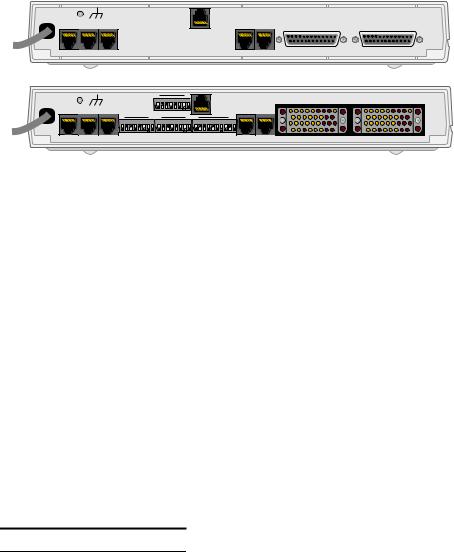
Port |
|
The rear of the PRISM 3111/3112, contains up to eight port connections as shown |
Connections |
in Figure 2-1: LAN, SLIP, SUPV, optional T1 DTE, NET, DBU, Data Port 1, and |
|
|
|
an optional Data Port 2 |
115VAC |
|
|
50/60Hz |
|
T1 |
120ma |
LAN SLIP SUPV |
DTE |
|
||
|
|
NET |
DBU |
DATA PORT 2 |
DATA PORT 1 |
115VAC |
|
|
|
1 |
|
|
|
|
|
|
8 |
|
|
50/60Hz |
|
|
|
N |
2 |
3 |
4 |
5 |
6 |
7 |
8 |
|
|
|
|
|
S4 |
O 1 |
|
T1 |
|||||||
120ma |
|
|
|
|
|
|
|
|
|
|
|
||
|
|
|
|
|
|
|
|
|
|
|
DTE |
||
LAN |
SLIP |
SUPV |
|
|
|
|
|
|
|
|
|
|
|
|
|
|
|
|
|
|
|
|
|
|
|||
|
|
1 |
8 |
1 |
|
|
|
|
|
|
8 |
1 |
10 |
O 1 2 3 4 5 6 7 8 O 1 2 3 4 5 6 7 8 O 1 2 3 4 5 6 7 8 9 10
N |
N |
N |
S1 S2 S3
DATA PORT 2 |
DATA PORT 1 |
NET |
DBU |
Figure 2-1 PRISM 3112 Rear Panel with and without LCD Option
LAN The PRISM 3111/3112 can be equipped with an internal Ethernet or Token Ring network interface card (NIC) for connection into a local area network (LAN). The connection is an 8-pin modular jack on the rear of the unit labeled LAN. The NIC can be installed without changing the rear panel. The LAN port will not function unless the optional NIC is installed.
The Simple Network Management Protocol (SNMP) agent can be programmed to take advantage of the centralized status monitoring and alarm reporting capability of SNMP managed networks. This unit is also compatible with the TXPORT 8100A Site Controller as a remote or far-end element. The 8100A is used to manage TXPORT network access products.
Ethernet
The Ethernet interface complies with standard twisted pair, 10BASE-T requirements. Table 2-1 displays the pinout assignments for the 8 -pin modular jack when configured for an Ethernet connection.
Table 2-1 Ethernet Pinout Assignments
Pin |
Ethernet Interface |
1Data Out (+)
2Data Out (-)
3Data In (+)
6 |
Data In (-) |
|
|
Configure the LAN interface before you connect the PRISM 3111/3112 to the LAN. Refer to the SNMP Configuration section on page 39 (front panel interface) or page 69 (terminal interface) for specific information.
Token Ring
The Token Ring interface is designed to operate on both 4 and 16 Mbps networks and complies with standard unshielded twisted pair requirements. The Token Ring interface is Type 3. Table 2-2 displays the pinout assignments for the 8 -pin modular jack when configured for a Token Ring connection.

Port Connections |
11 |
Table 2-2 Token Ring Pinout Assignments
Pin |
Token Ring Interface |
3Data Out (-)
4Data In (+)
5Data In (-)
6Data Out (+)
SLIP The SLIP port bit rates are configured through the front panel interface on page 42 for LCD units or through rear panel DIP switches S1-4 and S1-5 on page 16 for non-LCD units. It can be set to 1.2, 2.4, 9.6 or 19.2 kbps. This port is a DCE port configured for 8 bits, no parity, and 1 stop bit. The physical connections are 8 -pin modular jacks (electrically RS-232). Figure 2-2 provides the pinout assignments. See Ordering Information on page 92 for specific cable part numbers.
The SLIP port may be used to manage the unit. This port allows access to the embedded SNMP agent for trap reporting or SNMP management. You may access this port through either a direct or dial-up connection via an AT command set compatible modem. The modem should be optioned to ignore DTR, enable auto answer, inhibit command echo, and return verbose result codes.
If you call the unit and send the BREAK command before receiving the CONNECT message, the modem will hang-up.
SUPV The SUPV port bit rates are configured through the front panel interface on LCD units (page 42) or through the rear panel DIP switches on non-LCD units (page
SUPV /SLIP
DTR Out
RTS Out
Frame Gnd
Data Out
Data In
Signal Gnd
CTS In
DCD In
Port |
|
PC (DTE) |
1 |
1 |
DCD |
2 |
8 |
CTS |
3 |
5 |
Frame Gnd |
4 |
2 |
RXD |
5 |
3 |
TXD |
6 |
NC |
Signal Gnd |
7 |
7 |
RTS |
8 |
4 |
DTR |
8-Pin |
DB-9 |
Modular |
|
PRISM 3112 (LCD option) Rear Panel
115VAC |
|
|
|
|
DATA PORT 2 |
DATA PORT 1 |
50/60Hz |
|
|
T1 |
|
||
120ma |
SLIP |
SUPV |
DTE |
NET |
DBU |
|
LAN |
|
|
||||
|
|
|
|
|
|
PC |
|
|
|
RS-232 to Terminal |
|
||
|
|
|
PN# 9-1001-073-2 |
|
||
SUPV /SLIP
DTR Out
RTS Out
Frame Gnd
Data Out
Data In
Signal Gnd
CTS In
DCD In
Port |
1 |
2 |
3 |
4 |
5 |
6 |
7 |
8 |
Modem (DCE)
20 DTR
4 RTS
1Frame Gnd
2TXD
3RXD
7 Signal Gnd
5 CTS
8 DCD
8-Pin |
DB-25 |
Modular
PRISM 3112 (LCD option) Rear Panel
48VDC |
|
|
|
|
|
|
|
|
|
|
T1 |
|
|
|
|
LAN |
SLIP |
SUPV |
DTE |
NET |
DBU |
DATA PORT 2 |
DATA PORT 1 |
|
|
|
|
|
|
||
+ |
|
|
|
|
|
|
|
Modem
RS-232 to Modem
PN# 9-1001-091-1
Figure 2-2 SUPV and SLIP Terminal/Modem Connections

12 CHAPTER 2: INSTALLATION
11). It can be set to 1.2, 2.4, 9.6 or 19.2 kbps. This port is a DCE port configured for 8 bits, no parity, and 1 stop bit. The physical connections are 8-pin modular jacks (electrically RS-232). Figure 2-2 provides the pinout assignments. See Ordering Information on page 92 for cable information.
The terminal interface may be accessed through this port as well as the Call On Alarm feature. You may access this port through either a direct connection or a dial-up connection via an AT command set compatible modem. The modem should be optioned to ignore DTR, enable auto answer, inhibit command echo, and return verbose result codes.
If you call the unit and send the BREAK command before receiving the CONNECT message, the modem will hang-up.
T1 DTE The optional T1 DTE port is a DSX interface. The bit rates are configured through the front panel interface on LCD units (page 33), through the rear panel DIP switch S4 on non-LCD units (page 19) or through the terminal interface (page 61). The physical connection is an 8-pin modular jack. Table 2-3 provides the pinout assignments. T1 DTE port line coding is not dependent on the line coding of the network interface. ESF to D4 framing conversion is supported.
An RJ-48X modular jack and loopback (100 Ω+5%) is available for the T1 DTE port. Unlike an RJ-48C, the RJ-48X contains a shorting bar that engages when a cable is not plugged into the connector forcing the transmitted data to be looped back into the unit. When ordering a PRISM 311/3112 with an RJ-48X connector, specify option 2 (T1 DTE with loopback) for the T1 DTE selection.
Table 2-3 T1 DTE Pinout
Pin |
T1 DTE Interface |
1Data Out
2Data Out 3,6 Not Used
4Data In
5Data In
7, 8 Chassis Ground
NET The Network interface connection contains an automatic line build-out (ALBO) allowing the unit to be located a substantial distance away from the telco network interface with a receive signal level to -27 dB.
The network interface LBO level should be set as instructed in the Line Parameters section on page 58. Maximum suggested cable lengths for the connection from the
unit to the network are listed in Table 2-4. Calculations are based on a cable temperature of 70°F, 0.083 μF/mile capacitance, a 27 dB loss and a 100 Ω,
non-loaded, twisted pair cable.
Port Connections |
13 |
Table 2-4 Maximum Cable Lengths
Cable Type |
Loss per 1000' |
Max Cable Length |
|
|
|
26-gauge PIC |
6.8 dB |
4,400 ft |
24-gauge PIC |
5.4 dB |
5,500 ft |
22-gauge PIC |
4.2 dB |
7,100 ft |
19-gauge PIC |
3.0 dB |
10,000 ft |
PIC - Plastic Insulated Cable
The network physical interface is a standard RJ-48C, 8-pin modular jack. Table 2-5 displays the pinout assignments.
Table 2-5 Network Interface Pinout
Pin T1 NET Interface
1Data In
2Data In 3, 6 Not used
4Data Out
5Data Out
7, 8 Chassis Ground
In accordance with FCC Rules, Part 68.218(b), you must notify the telephone company prior to disconnecting this product.
DBU The Dial Back-Up (DBU) port provides an alternate path when the T1 network interface service is disrupted or performance quality is degraded. This port is a 10-pin, RS-232 port that can connect, through a connector adapter, to a public switched digital network (PSDN) device. Table 2-6 displays the pinout assignments. See page 36 (front panel interface) or page 65 (terminal interface) for information on DBU parameters and settings.
Table 2-6 DBU Port Pinout
Pin Connection
1Rx Clock In
2DTR Out
3RTS Out
4Frame Ground
5Data Out
6Data In
7Signal Ground
8CTS In

14 CHAPTER 2: INSTALLATION
Table 2-6 DBU Port Pinout
Pin |
Connection |
|
|
9 |
DCD In |
10 |
Tx Clock In |
|
|
Data Port The PRISM 3111 is equipped with either a V.35 port (on a standard 34-pin Connections connector) or an EIA-530 port (on a standard 25-pin connector). The PRISM 3112
is available with two ports. Pin functions for the high speed port interface are listed in Table 2-7.
FCC rules require that interconnecting cables carrying high speed data be shielded appropriately in order to minimize radio frequency interference.
Table 2-7 High Speed DTE Interface
Common Name |
V.35 (34-pin) |
EIA-530 (25-pin) |
|
|
|
Frame Ground |
A |
1 |
Transmit Data |
P, S |
2, 14 |
Receive Data |
R, T |
3, 16 |
Request to Send |
C |
4, 19 |
Clear to Send |
D |
5, 13 |
Data Set Ready |
E |
6, 22 |
Signal Ground |
B |
7 |
Data Carrier Detect |
F |
8, 10 |
Transmit Clock |
Y, AA |
12, 15 |
Receive Clock |
V, X |
9, 17 |
Local Loopback |
J |
18 |
Data Term Ready |
H |
20, 23 |
Remote Loopback |
BB |
21 |
Terminal Timing |
U, W |
11, 24 |
|
|
|
Power Connection The PRISM 3111/3112 can be powered by either an AC or DC suppy. When power is applied to the unit, the front panel indicators flash for approximately five seconds as the unit initializes. The green power LED on the front panel will remain illuminated as long as the unit receives power.
AC Power
AC powered units use a 115 VAC captive power supply. There is no power switch.
Per UL 1950 and CSA 950 Clause 1.7.2, if the power supply cord is intended to serve as a disconnect device, a socket must be installed near the equipment and be easily accessible.
DIP Switch Settings |
15 |
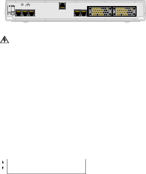
DC Power
The -48 VDC powered units have two terminal block connections labeled positive (+) and negative (-) that accept wire sizes from 12-gauge to 20-gauge. Either polarity (positive or negative) may be referenced to ground.
48VDC
LAN |
SLIP |
SUPV |
+ |
|
|
T1 |
|
DATA PORT 2 |
DATA PORT 1 |
|
|
|
|
DTE |
NET |
DBU |
|
|
|
Figure 2-3 48 VDC back panel (PRISM 3112, LCD option shown)
The unit is protected from reverse power connection.
Power Failure If the indicator does not illuminate, recheck the power connections. For AC
|
powered units, check the primary AC circuit breaker. |
|
The PRISM 3111/3112 provides non-volatile memory retention of the unit |
|
configuration in case of a power failure. This feature allows the unit to |
|
automatically restore normal service following a power loss. |
DIP Switch |
The PRISM 3111/3112 can be ordered with the Dual In-line Package (DIP) |
Settings |
switches located on the rear of the unit. These switches perform the basic |
|
configuration settings found in the terminal and front panel interfaces. |
Switch S1 Switch S1 (Figure 2-4) configures the boot mode, SUPV Port Bit Rate, SLIP Port Bit Rate, Channel Assignments, Data Port 1, and Data Port 2. The SUPV and SLIP bit rates (S1-2 through S1-5) cannot be set or modified through the terminal interface.
Up |
Boot Mode |
SUPV Port Bit Rate |
SUPV Port Bit Rate |
SLIP Port Bit Rate |
SLIP Port Bit Rate |
Channel Assignment |
Data Port 1 Rate Multiplier |
Data Port 2 Rate Multiplier |
|||||||||||||||||
|
|
|
|
|
|
|
|
|
|
|
|
|
|
|
|
|
|
|
|
|
|
|
|
||
|
|
|
|
|
|
|
|
|
|
|
|
|
|
|
|
|
|
|
|
|
|
|
|
|
|
|
|
|
|
|
|
|
|
|
|
|
|
|
|
|
|
|
|
|
|
|
|
|
|
|
|
|
|
|
|
|
|
|
|
|
|
|
|
|
|
|
|
|
|
|
|
|
|
|
|
|
|
|
|
|
|
|
|
|
|
|
|
|
|
|
|
|
|
|
|
|
|
|
|
|
|
|
|
Dn
1 |
2 |
3 |
4 |
5 |
6 |
7 |
8 |
Figure 2-4 Switch S1
Boot Mode
Switch S1-1 determines whether the unit configures itself from the DIP switches or from the battery backed RAM. If set to boot from RAM (Up), the switch settings are ignored. If set to boot from switches (Dn), the unit reads the DIP switches on power-up and configures accordingly. Once running, configuration changes can be made through the switches. The unit will automatically reconfigure itself to the new switch settings. You can also make changes through the terminal interface (Chapter 4), overriding the switch settings.

16CHAPTER 2: INSTALLATION
If the boot mode is set to Boot From Switches (S1-1=Dn) and you change any other configuration switch, the unit will configure all possible parameters from the switch settings.
SUPV Port Bit Rate
Switch S1-2 and S1 -3 set the supervisory port bit rate. This is a serial RS-232 DCE port configured for 8 bits, no parity, and 1 stop bit. Table 2-8 shows the available speeds.
Table 2-8 SUPV Port Bit Rate
S1-2 S1-3 |
SUPV Port Rate |
|
|
|
|
Up |
Up |
1.2 kbps |
Dn |
Up |
2.4 kbps |
Dn |
Dn |
9.6 kbps |
Up |
Dn |
19.2 kbps |
|
|
|
SLIP Port Bit Rate
Switch S1 -4 and S1- 5 set the SLIP port bit rate. This is a serial RS-232 DCE port configured for 8 bits, no parity, and 1 stop bit. Table 2-9 shows the available speeds.
Table 2-9 SLIP Port Bit Rate
S1-4 S1-5 |
SLIP Port Rate |
|
|
|
|
Up |
Up |
1.2 kbps |
Dn |
Up |
2.4 kbps |
Dn |
Dn |
9.6 kbps |
Up |
Dn |
19.2 kbps |
|
|
|
Channel Assignment
Switch S1-6 selects the channel assignment mode for network T1 DS0s carrying data to the high speed port. Contiguous channel mode (Dn) assigns the channels as a block beginning at channel one for Data Port 1 and the first available channel for Data Port 2, if installed. For example, if the high speed port data rate is to be 256 kbps (as defined by Switch S3), the unit assigns network channels one through four to the high speed port.
Alternate (Up) channel mode assigns an idle channel following each data channel. For example, data are carried on channels 1, 3, 5 and 7. Channels 2, 4, 6 and 8 are idle (the idle setting is binary code 01111111). The advantage of alternate channel assignment is that T1 ones density requirements are maintained by the idle channels rather than placing any restrictions on the high speed data.
Data Port 1
Switch S1-7 sets the multiplier for the Data Port 1 input timing. The unit can operate at any data rate that is a multiple of 56 or 64 kbps. Selecting Nx64K (Dn) provides port bit rates that are multiples of 64 kbps. The ones density requirements of the T1 network line must be ensured in this mode. Refer to the section entitled Line Parameters on page 58 for more information. Selecting Nx56K (Up) allows

DIP Switch Settings |
17 |
port bit rates that are multiples of 56 kbps. The unit maintains ones density for the selected DS0 channels in this mode.
Data Port 2
Switch S1-8 sets the multiplier for Data Port 2 on the 3112 only. The unit can operate at any data rate that is a multiple of 56 or 64 kbps. Selecting Nx64K (Dn) provides port bit rates that are multiples of 64 kbps. The ones density requirements of the T1 network line must be ensured in this mode. Refer to the front panel Rate selection option on page 34 for more information. Selecting Nx56K (Up) allows port bit rates that are multiples of 56 kbps. The unit maintains ones density for the selected DS0 channels in this mode.
Switch S2 Switch S2 (Figure 2-5) configures parameters for Network Framing, Network Coding, Network LBO, Timing Source, Test Button Loop Code, and Test Button Mode.
Up |
Network Framing |
Network Coding |
Network LBO |
Network LBO |
Timing Source |
Timing Source |
Test Button Loop Code |
Test Button Mode |
|||||||||||||||||
|
|
|
|
|
|
|
|
|
|
|
|
|
|
|
|
|
|
|
|
|
|
|
|
||
|
|
|
|
|
|
|
|
|
|
|
|
|
|
|
|
|
|
|
|
|
|
|
|
|
|
|
|
|
|
|
|
|
|
|
|
|
|
|
|
|
|
|
|
|
|
|
|
|
|
|
|
|
|
|
|
|
|
|
|
|
|
|
|
|
|
|
|
|
|
|
|
|
|
|
|
|
|
|
|
|
|
|
|
|
|
|
|
|
|
|
|
|
|
|
|
|
|
|
|
|
|
|
|
Dn
1 |
2 |
3 |
4 |
5 |
6 |
7 |
8 |
Figure 2-5 Switch S2
Network Framing
Switch S2-1 matches the unit to the network line framing as either ESF (Dn) or D4 (Up).
Network Coding
Switch S2-2 sets the network line coding to either B8ZS (Dn) or AMI (Up).
Network LBO
Switch S2-3 and S2 -4 set the line build out signal level of the transmit data (TXD) from the unit to the network. The telephone company can provide the proper setting. If unsure of the exact setting, leave it at the default value.
Table 2-10 lists the available levels.
Table 2-10 Network LBO
S2-3 S2-4 |
Network LBO |
|
|
|
|
Dn |
Dn |
0 dB |
Up |
Dn |
-7.5 dB |
Dn |
Up |
-15.0 dB |
Up |
Up |
-22.5 dB |
|
|
|

18 CHAPTER 2: INSTALLATION
Timing Source
Switch S2-5 and S2 -6 determine the unit clocking source. The most common timing source for CSU/DSU applications is the network. The 3111/3112 may also be optioned to time from an internal standard or from the high speed data interface as shown in Table 2-11.
Table 2-11 Timing Source
S2-5 S2-6 |
Timing Source |
|
|
|
|
Dn |
Dn |
Network |
Up |
Dn |
Internal |
Dn |
Up |
Port 1 EXC |
Up |
Up |
T1 DTE |
|
|
|
Test Button Loop Code
Switch S2-7 selects either an inband line loopback code (Dn) or an inband V.54 loop code (Up) for use with the front panel test button. If selected to Up, the front panel test button performs a test on Data Port 1 only.
Test Button Mode
Switch S2-8 selects the test to be run when the Test button is pressed. Options are BERT (Dn) or Clear (Up). Clear does not generate a pattern, it only disables alarm monitoring and reporting.
Switch S3 Switch S3 (Figure 2-6) sets the Port 1 and Port 2 bit rates as shown in
Table 2-12 The bit rates are determined by the rate multiplier (Nx56 or Nx64) as configured through S1-7 (Port 1) and S1-8 (Port 2) on page 15. Positions S3-6 through S3 -10 are not applicable on the 3111
Anyinstalled.channel not mapped to a port is allocated to the T1 DTE if that option card is
Up
Port 1 Bit Rate |
|
|
|
Port 2 Bit Rate |
||||||||||||
|
|
|
|
|
|
|
|
|
|
|
|
|
|
|
|
|
|
|
|
|
|
|
|
|
|
|
|
|
|
|
|
|
|
|
|
|
|
|
|
|
|
|
|
|
|
|
|
|
|
|
Dn
1 |
2 |
3 |
4 |
5 |
6 |
7 |
8 |
9 |
10 |
Figure 2-6 Switch S3

DIP Switch Settings |
19 |
Table 2-12 Port 1/Port 2 Bit Rates
|
|
|
|
|
|
|
kbps if |
kbps if |
|
# of |
Port 1 |
S3-1 |
S3 -2 |
S3-3 |
S3-4 |
S3-5 |
S1-7 |
S1-7 |
|
(S1-8) |
(S1-8) |
||||||||
|
|||||||||
DS0s (Port 2) |
(S3-6) |
(S3-7) |
(S3-8) |
(S3-9) (S3-10) |
is Up |
is Dn |
|||
|
|
|
|
|
|
|
|
||
|
|
Dn |
Dn |
Dn |
Dn |
Dn |
Disabled |
||
1 |
|
Up |
Dn |
Dn |
Dn |
Dn |
56 |
64 |
|
2 |
|
Dn |
Up |
Dn |
Dn |
Dn |
112 |
128 |
|
3 |
|
Up |
Up |
Dn |
Dn |
Dn |
168 |
192 |
|
4 |
|
Dn |
Dn |
Up |
Dn |
Dn |
224 |
256 |
|
5 |
|
Up |
Dn |
Up |
Dn |
Dn |
280 |
320 |
|
6 |
|
Dn |
Up |
Up |
Dn |
Dn |
336 |
384 |
|
7 |
|
Up |
Up |
Up |
Dn |
Dn |
392 |
448 |
|
8 |
|
Dn |
Dn |
Dn |
Up |
Dn |
448 |
512 |
|
9 |
|
Up |
Dn |
Dn |
Up |
Dn |
504 |
576 |
|
10 |
|
Dn |
Up |
Dn |
Up |
Dn |
560 |
640 |
|
11 |
|
Up |
Up |
Dn |
Up |
Dn |
616 |
704 |
|
12 |
|
Dn |
Dn |
Up |
Up |
Dn |
672 |
768 |
|
13 |
|
Up |
Dn |
Up |
Up |
Dn |
728 |
832 |
|
14 |
|
Dn |
Up |
Up |
Up |
Dn |
784 |
896 |
|
15 |
|
Up |
Up |
Up |
Up |
Dn |
840 |
960 |
|
16 |
|
Dn |
Dn |
Dn |
Dn |
Up |
896 |
1024 |
|
17 |
|
Up |
Dn |
Dn |
Dn |
Up |
952 |
1088 |
|
18 |
|
Dn |
Up |
Dn |
Dn |
Up |
1008 |
1152 |
|
19 |
|
Up |
Up |
Dn |
Dn |
Up |
1064 |
1216 |
|
20 |
|
Dn |
Dn |
Up |
Dn |
Up |
1120 |
1280 |
|
21 |
|
Up |
Dn |
Up |
Dn |
Up |
1176 |
1344 |
|
22 |
|
Dn |
Up |
Up |
Dn |
Up |
1232 |
1408 |
|
23 |
|
Up |
Up |
Up |
Dn |
Up |
1288 |
1472 |
|
24 |
|
Dn |
Dn |
Dn |
Up |
Up |
1344 |
1536 |
|
|
|
|
|
|
|
|
|
|
|
Switch S4 Switch S4 (Figure 2-7) configures the T1 DTE port. Any channel not mapped to a data port is mapped to the T1 DTE port. Framing and linecoding on the T1 DTE is independent of T1 framing and linecoding.
Up |
DTE Framing |
DTE Coding |
DTE LBO |
DTE LBO |
DTE LBO |
DTE Sig Insert |
Not Used |
|
Not Used |
||||||||||
|
|
|
|
|
|
|
|
|
|
|
|
|
|
|
|
|
|
||
|
|
|
|
|
|
|
|
|
|
|
|
|
|
|
|
|
|
|
|
|
|
|
|
|
|
|
|
|
|
|
|
|
|
|
|
|
|
|
|
|
|
|
|
|
|
|
|
|
|
|
|
|
|
|
|
|
|
|
|
|
|
|
|
|
|
|
|
|
|
|
|
|
|
|
|
|
|
|
|
Dn
1 |
2 |
3 |
4 |
5 |
6 |
7 |
8 |
Figure 2-7 Switch S4
20 CHAPTER 2: INSTALLATION
DTE Framing
Switch S4-1 selects the framing type for the DTE side of the element as either
ESF (Dn) or D4 (Up).
DTE Coding
Switch S4-2 sets the DTE side line coding as either B8ZS (Dn) or AMI (Up).
DTE DSX Level
Switch S4-3, S4-4, and S4-5 set the DTE line build-out signal level as identified in Table 2-13.
Table 2-13 |
DTE DSX |
|
|
|
|
|
|
|
S4-3 |
S4-4 |
S4-5 |
|
|
|
|
0-110 ft |
Dn |
Dn |
Dn |
111-220 ft |
Up |
Dn |
Dn |
221-330 ft |
Dn |
Up |
Dn |
331-440 ft |
Up |
Up |
Dn |
441-550 ft |
Dn |
Dn |
Up |
551-660 ft |
Up |
Dn |
Up |
660 ft > |
Don’t Care |
Up |
Up |
|
|
|
|
DTE Sig Insert
This switch allows you to Enable (Up) or Disable (Dn) signalling insertion for all channels mapped to the T1 DTE.

3 |
FRONT PANEL |
|
INTERFACE |
||
|
Depending on your ordering options, the PRISM 3111/3112 front panel comes with or without an LCD screen option and option specific control buttons.
Non-LCD Option The non-LCD front panel interface option (Figure 3-1) allows you to troubleshoot the unit using loop tests without having to connect a terminal to the unit. The tests can be run using the two front panel buttons. The five LED indicators allow you to see the unit’s status.

 ®
®
TEST LOOP
NET BACKUP TEST ALARM POWER
PRISM 3111
Figure 3-1 PRISM 3111/3112 Front Panel (non-LCD option)
LEDs Five front panel LEDs allow a visual identification of the test results and alarms. These LEDs are: NET, BACKUP, TEST, ALARM, and POWER.
NET
This LED illuminates green when the unit is in frame sync. It illuminates amber when the unit receives a yellow alarm from the far end. It illuminates red when the unit is out of frame and/or loss of signal.
BACKUP
Amber LED blinks when dialing, connecting, or disconnecting. It illuminates when active.
TEST
This LED flashes green when the unit is transmitting loop code. It is green continuously when BERT is on with no errors, when the unit is in a loop condition, or when the unit is in clear test. It is red when the BERT is on and is receiving errors.
ALARM
Red LED illuminates when the unit is in an active alarm condition.
POWER
Green LED illuminates when power is applied to the unit.

22 CHAPTER 3: FRONT PANEL INTERFACE
Buttons Two front panel buttons allow you to send loop tests.
TEST
When this button is pushed once, the unit transmits five seconds of in-band loop code out to the network either LLB or V.54 depending on the setting of configuration Switch S2 -7 (page 18). If S2-7 is set to V.54, this button performs a test on Data Port 1 only. The indicator blinks green during transmission of the loop code.
If configuration Switch S2 -8 (page 18) is set to Clear Loop, the unit goes into a test mode where it will not generate alarms.
If Switch S2 -8 is set to BERT, the test pattern last selected in the terminal interface is transmitted toward the network. The received pattern is compared and if the pattern is received error free, the TEST indicator remains green. If pattern errors are detected, the TEST indicator turns red for one second for each errored second. Therefore, if five errored seconds are received, the indicator will remain red for five seconds.
If the TEST button is pushed again, the unit transmits five seconds of in-band loop down code and returns to normal operating mode. The TEST indicator is then turned off.
LOOP
When this button is pressed once, the unit activates a line loopback, looping the network receive data back to the network (Net LLB). The TEST indicator is illuminated while the unit is in loop. If pressed again, the unit clears the loop and turns off the LOOP indicator.
For additional information concerning test and loop options, refer to page 28.
LCD Option
The LCD front panel interface option (Figure 3-2) allows you to configure network, port, and SNMP parameters and troubleshoot the unit using loop tests and BERTs without having to physically connect a terminal to the unit. The interface screen can be manipulated using the three front panel buttons. The interface screen and the four LED indicators allow you to see the unit’s status.
®
EXIT SCROLL SELECT
BACKUP TEST ALARM POWER
PRISM 3111
Figure 3-2 PRISM 3111/3112 Front Panel (LCD option)
LEDs Four front panel LEDs allow a visual identification of the test results and alarms. These LEDs are: BACKUP, TEST, ALARM and POWER.
 Loading...