

OMNI 3600 TERMINAL
Install/Replace MSAM Cards
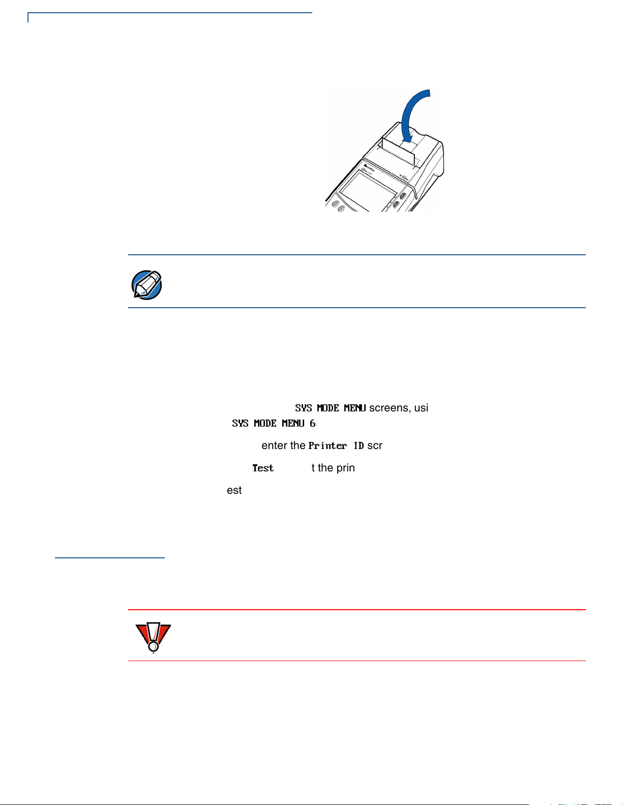
Figure 8 Close the Printer Cover
NOTE
Printer Test
Install/Replace
MSAM Cards
To prevent damage to the print roller on the paper roll cover, always close the
cover by gently pressing down on the paper roll cover tab.
To ensure the printer is operating correctly:
1 Turn on the terminal by pressing the green enter key (see Figure 2, page 10).
2 Enter system mode by pressing F2+F4 at the initial copyright screen, and
entering the system mode password (see Passwords).
3 Toggle through the
reach
SYS MODE MENU 6
4 Press F4 to enter the
5 Press F3,
The test printout, with printer information and repeating character strings, is
approximately 38 cm (15 in.) long.
When you first receive your Omni 3600 terminal, you may need to install a
merchant smart card or one or more micromodule-sized security account
manager (MSAM) cards, or you may need to replace old cards. Often, these small
cards arrive on a larger, credit card-style plastic card, from which they must be
removed. The following procedure describes MSAM card installation.
Test
SYS MODE MENU
.
Printer ID
, to start the printer self-test.
screens, using the down arrow key until you
screen.
CAUTION
Observe standard precautions for handling electrostatically sensitive devices.
Electrostatic discharges can damage this equipment. An anti-static wrist strap
grounded to a metal surface is recommended.
1 Remove the battery (see Smart Battery)
2 Open the MSAM door located beneath the battery (Figure 9):
16 OMNI 3600 INSTALLATION GUIDE
a Push down and back on the raised arrow on the door.
b Lift up on the raised arrow with the tip of your index finger.
OMNI 3600 TERMINAL
Install/Replace MSAM Cards
c Open the door until it is in the upright position, resting against the end of
the terminal.
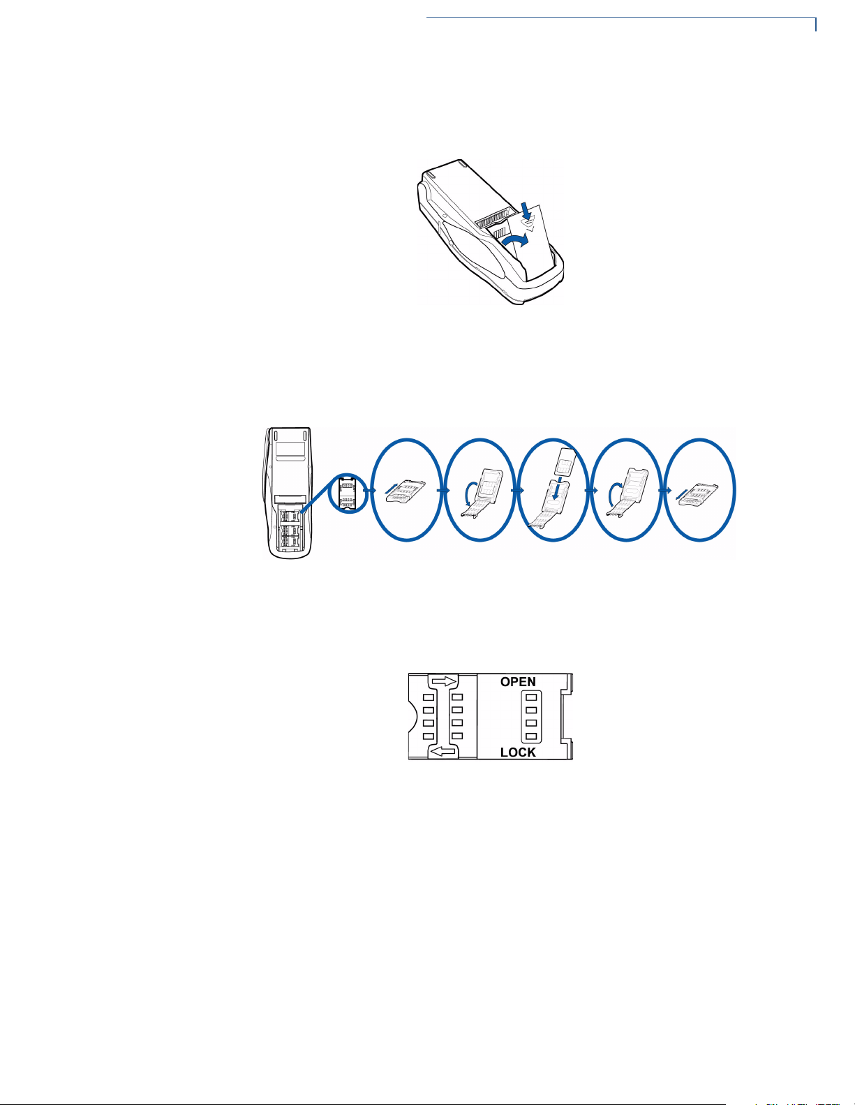
Figure 9 Open the MSAM Access Door
The three MSAM cardholders are now accessible. Each cardholder consists of
a hinged tilt-up cover attached to a connector base (Figure 10).
Figure 10 MSAM Card Installation
3 Access the MSAM cardholders (reference Figure 10):
a Unlock the cardholder: Slide the lock plate to the unlocked position, in the
OPEN direction (Figure 11).
Figure 11 MSAM Cardholder Lock Plate Detail
O
MNI 3600 INSTALLATION GUIDE 17
OMNI 3600 TERMINAL
Install/Replace SIM Card (GSM models)
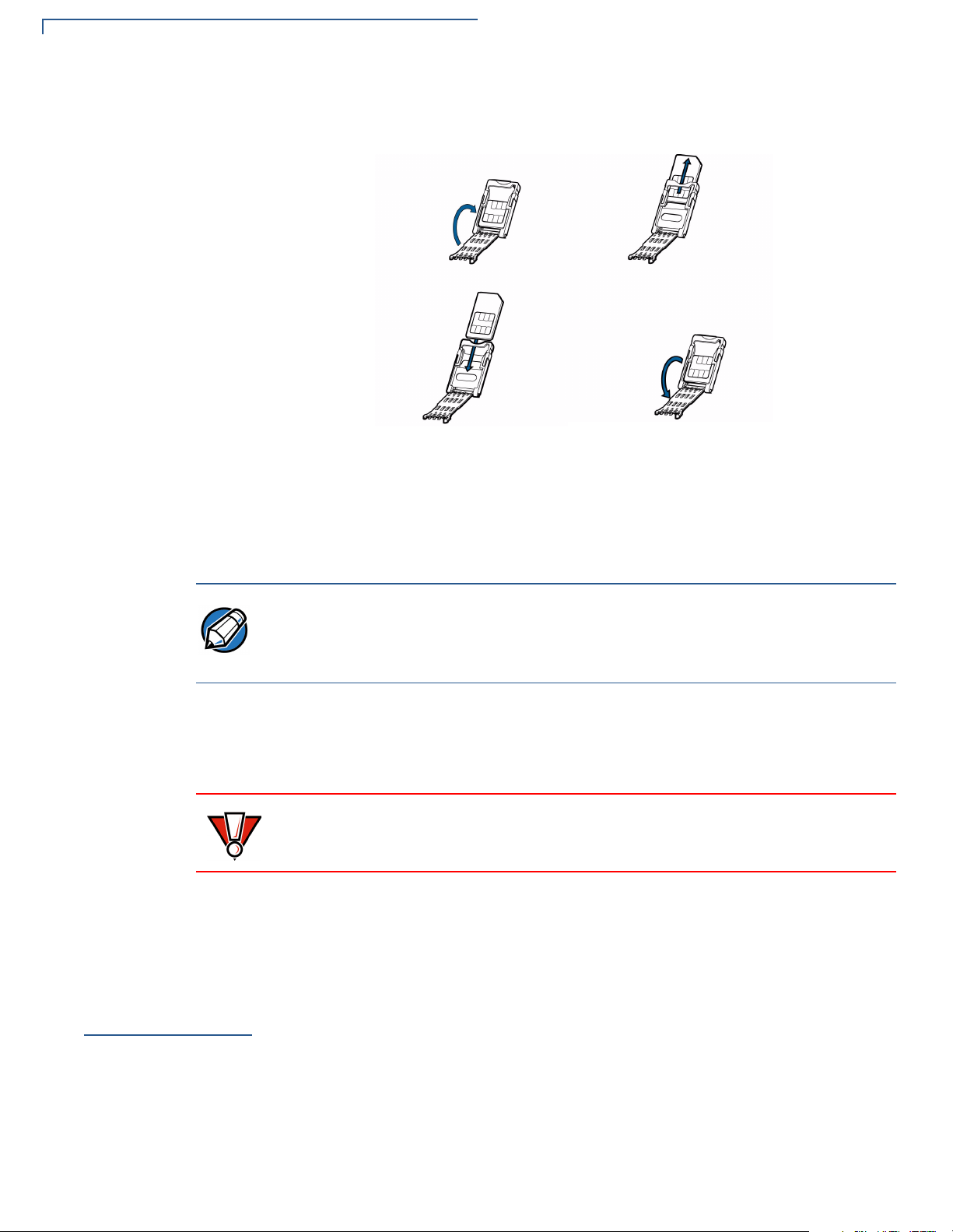
Figure 12 Insert MSAM Card into Cardholder
4 Remove any previously installed MSAM card by sliding the card from the
b Open the cardholder by pivoting the cover on its hinge away from the
connector base (Figure 12).
cover.
NOTE
CAUTION
Install/Replace
SIM Card (GSM
models)
5 Install an MSAM card by aligning the card and carefully sliding it within the
guides on the cover until fully inserted.
The cardholder has a set of contacts and a notch on one corner to ensure the
MSAM card is positioned correctly when the cover is closed. The MSAM card has
a notch on one corner to ensure it is correctly positioned in the cardholder. Before
inserting the MSAM card, position it as shown in Figure 12.
6 Close the cover (Figure 12).
7 Lock each MSAM cardholder by sliding its locking plate towards the LOCK
arrow until the plate stops (Figure 11).
To avoid damage to the MSAM cardholders, ensure each cardholder is locked
before closing the MSAM door.
8 Close the MSAM door.
9 Replace the smart battery.
The SIM (Subscriber Identity Module) card is a smart card inserted in the
Omni 3600 GSM terminal that contains your GSM radio account information. Use
the following procedure to replace or install a SIM card.
18 OMNI 3600 INSTALLATION GUIDE
OMNI 3600 TERMINAL
NOTE
Install/Replace SIM Card (GSM models)
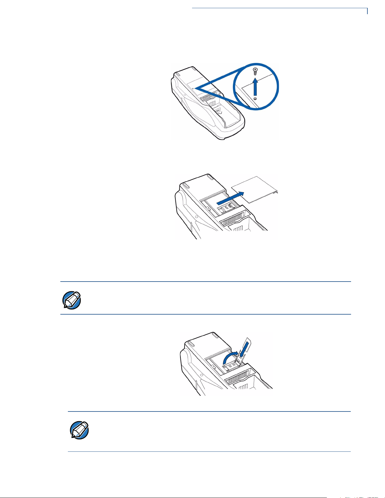
1 Remove screw from SIM card access door on back of Omni 3600 terminal
(Figure 13).
Figure 13 Remove SIM Door Screw
2 Remove the SIM card access door (Figure 14):
NOTE
Figure 14 Slide Off SIM Card Access Door
3 Open the SIM card holder and slide the SIM card supplied by your provider
into the cardholder (Figure 15).
Do not lose the SIM card dust cover or retaining screw.
Figure 15 Insert SIM Card into Cardholder
The SIM cardholder has a notch on one corner to ensure the SIM card is
positioned correctly. The SIM card has a notch on one corner for easy orientation
in the cardholder. Before inserting the SIM card, position it as shown in Figure 15,
with the card’s gold contacts facing down.
4 Replace the SIM card access door and screw.
O
MNI 3600 INSTALLATION GUIDE 19
OMNI 3600 TERMINAL
Wireless Transactions
Wireless
Transactions
Smart Card
Reader
Transactions
To conduct a wireless transaction:
• Ensure the terminal is in an optimal position for transmitting.
• Follow the on-screen instructions provided with your application.
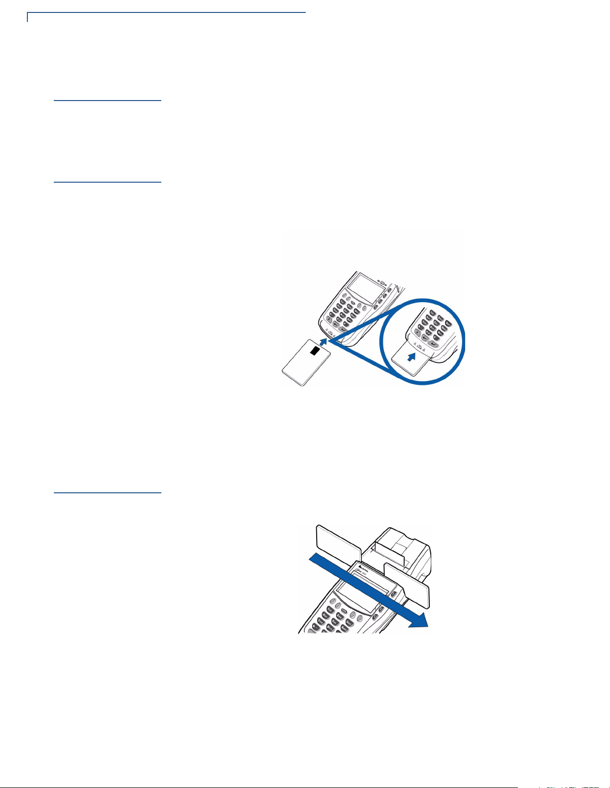
To conduct a smart card transaction:
1 Position the smart card with the contacts up and insert it into the smart card
reader slot in a smooth, continuous motion until it seats firmly (Figure 16).
Leave the smart card in the card reader until the transaction is complete.
Premature removal voids the transaction.
Magnetic Card
Reader
Transactions
Figure 16 Using the Primary Smart Card Reader
2 Remove the card when the display indicates the transaction is complete.
To conduct a credit/debit card transaction:
1 Position the card with the magnetic stripe facing down and towards the printer.
2 Swipe it through the reader from left-to-right, as shown in Figure 17.
Figure 17 Using the Magnetic Card Reader
20 OMNI 3600 INSTALLATION GUIDE
OMNI 3600 TERMINAL
Antenna (Some Wireless Models)
Antenna (Some
Wireless
Models)
NOTE
CAUTION
Installation
For some Omni 3600 terminals to establish a wireless connection, an external
antenna is provided. This connection allows communication with your service
provider to upload transaction data from the terminal and download system
upgrades to the terminal. Radio service is activated by your service provider.
Most Omni 3600 terminals have an internal antenna and this section can be
ignored.
Only use the antenna designed for your unit. Failure to use the proper antenna
results in the inability to establish a wireless connection.
Never hold the unit by the antenna; doing so may break the connection and void
your warranty.
Data transfers can also be performed through the Omni 3600 base (see
Omni 3600 Base Communications Ports).
This section only discusses Omni 3600 terminals with external antenna.
The Omni 3600 should arrive from manufacture with the antenna attached. If
unattached, use the following procedure to install the antenna:
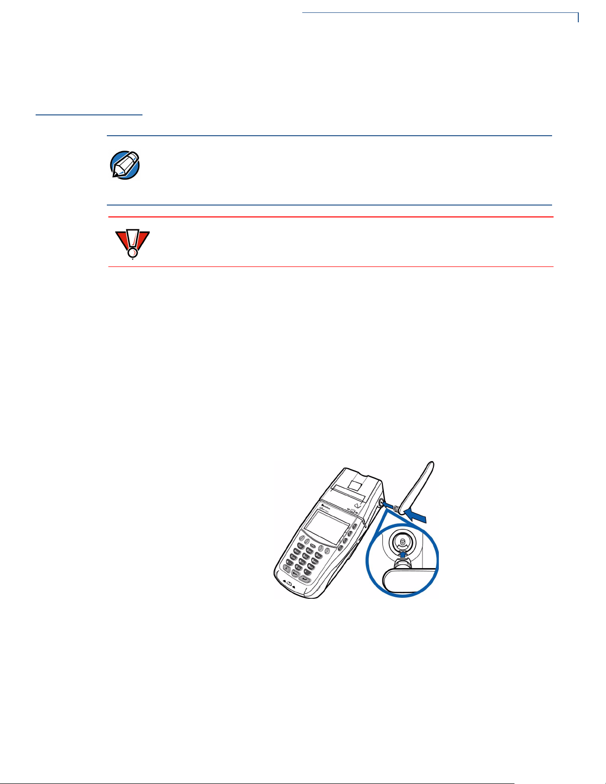
Orientation
1 Locate the antenna port on the side of the Omni 3600 terminal.
2 Align the respective “notch” inside the antenna to the key in the terminal
(Figure 18).
3 Push gently on the center of the base of the antenna until it locks in position.
Figure 18 Antenna Installation
To establish good wireless communication (uplink), it is important that the antenna
always be vertically aligned with respect to ground and sky (Figure 19). For
example, if standing and holding the terminal horizontally, position the antenna at
an approximately 90° angle to the unit (that is, pointing up from the printer). This
should point the antenna directly at the sky.
O
MNI 3600 INSTALLATION GUIDE 21
OMNI 3600 TERMINAL
Antenna (Some Wireless Models)
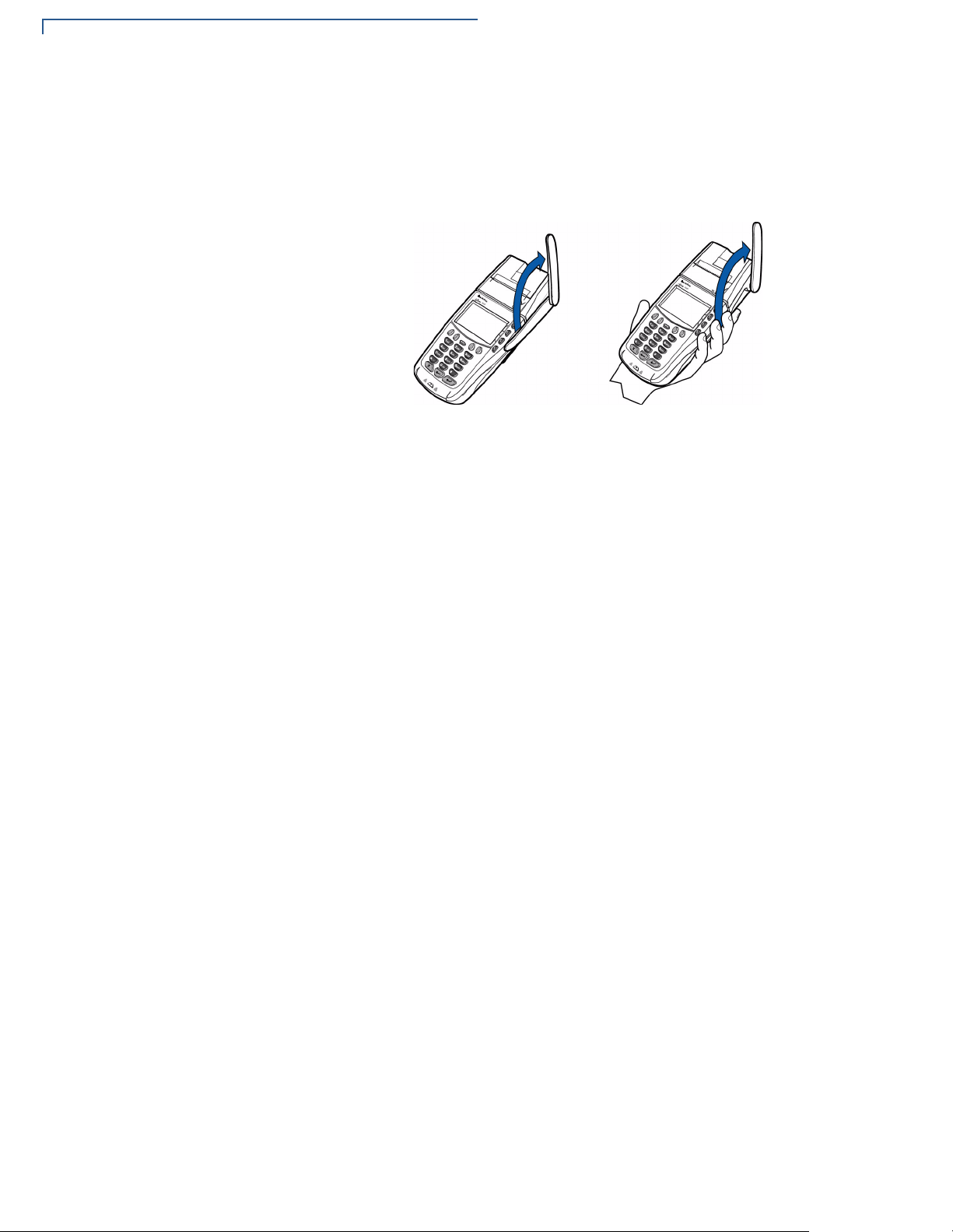
If the unit is on a flat surface (for example, a table top) or docked in the Omni 3600
base, position the antenna so that it points directly at the sky. Soft detentes are
felt and clicks heard when positioning the antenna. These detentes maintain
antenna positions of 60°, 90°, and 180° .
Figure 19 Correct Antenna Position for Uplink
If an application (for example, SoftPay) is installed in your Omni 3600 unit, a
signal strength indicator may appear on the display.
Replace the
Antenna
If your Omni 3600 terminal has difficulties completing wireless transactions, you
may have to replace the antenna. Use the following procedure to replace the
antenna:
1 Remove the existing antenna from the Omni 3600 terminal:
a Rotate the antenna to align with the base of the unit, pointing away from
the back.
b Grasp the base of the antenna, close to the body of the terminal.
c Pull gently out until the antenna unsnaps from the antenna port.
2 Align the respective notch inside the new antenna to the key in the antenna
port on the terminal (Figure 18).
3 Push gently on the center of the base of the newly installed antenna until it
locks in position.
22 OMNI 3600 INSTALLATION GUIDE
Omni 3600 Base
CHAPTER 3
This section discusses the features of the Omni 3600 base, including
• providing power to the Omni 3600 base,
• docking the Omni 3600 terminal,
• charging the smart battery in a docked terminal,
• charging a spare smart battery,
• establishing communications, and
• connecting peripheral devices.
The Omni 3600 base does not support PIN pad connections.
Unpack the
Shipping
Carton
NOTE
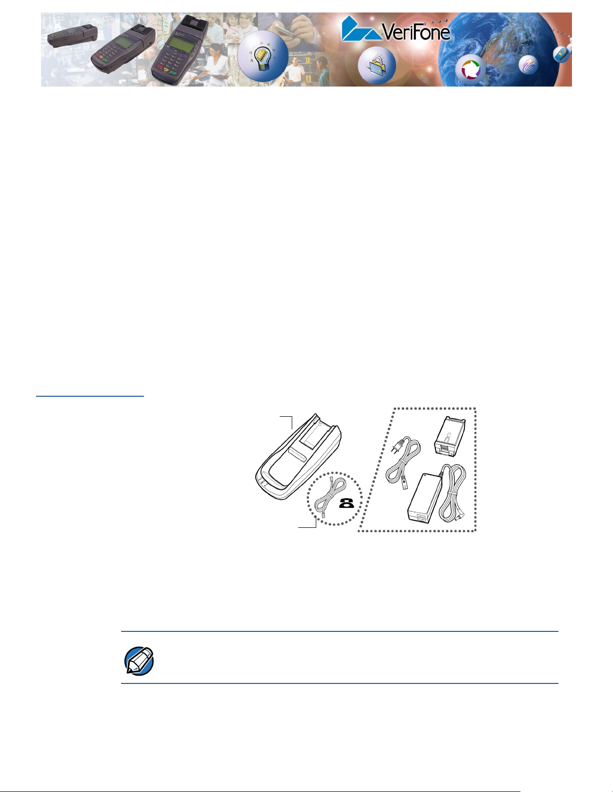
Refer to Figure 20 and the following procedure while unpacking the Omni 3600
base shipping carton.
OPTIONAL ACCESSORIES
OMNI 3600
BASE
TELCO CABLE
(OPTIONAL)
Figure 20 Omni 3600 Base Shipping Carton Contents
1 Remove the following items:
• Omni 3600 base
• Telco cable (optional)
The power pack and power cable, spare battery packs, and Telco cable are
available separately. See Accessories and Documentation for ordering
information.
2 Remove all plastic wrap from the Omni 3600 base and other components.
OMNI 3600 INSTALLATION GUIDE 23
OMNI 3600 BASE
Omni 3600 Base Features
Omni 3600
Base Features
CAUTION
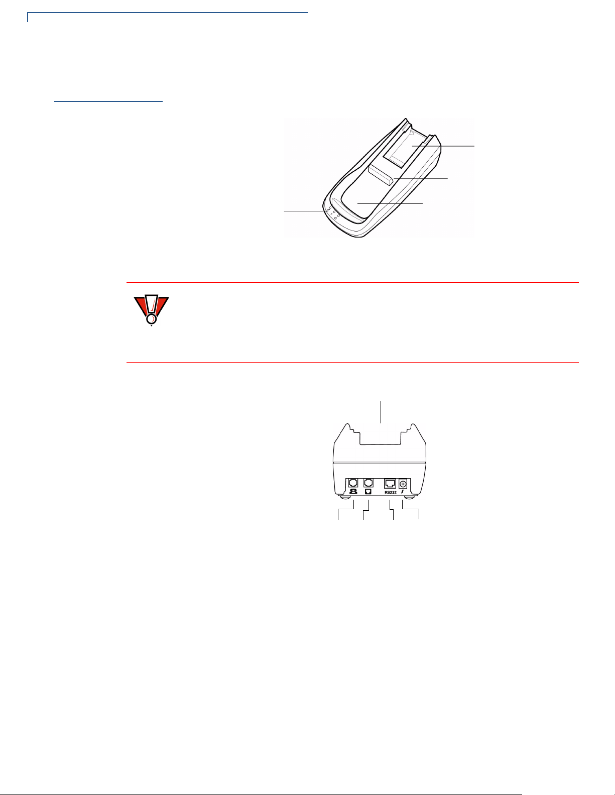
This section discusses the features of the Omni 3600 base.
SPARE BATTERY
DOCK
TERMINAL DOCKING
CONTACTS
TERMINAL DOCKING
STATUS LEDS
CRADLE
Figure 21 Omni 3600 Base Features: Top
Avoid touching the contacts in the raised area in the center of the Omni 3600
base. Finger oils tarnish contacts, causing bad connections. If the battery charge
state or terminal power LEDs do not light when the terminal is docked, or there is
a high occurrence of bad or incomplete data transfers, clean the contacts. See
Maintenance for more information.
TERMINAL DOCKING
CRADLE
TELSET
PORT
TELCO
PORT
RS-232
PORT
POWER
PORT
Figure 22 Omni 3600 Base Features: Back (Telco models)
The Omni 3600 base
• recharges the smart battery within a docked Omni 3600 terminal,
• charges a spare smart battery pack placed in the spare battery dock,
• establishes communications to a host through a 14.4 Kbps modem (Telco
port), and
• connects to optional peripherals through the serial (RS-232) port (see
Peripheral Devices).
The following are the physical features of the Omni 3600 base (Figure 21 and
Figure 22):
• Three status LEDs (light emitting diodes) viewed left-to-right
24 OMNI 3600 INSTALLATION GUIDE

OMNI 3600 BASE
Omni 3600 Base Features
• Terminal power LED:
• Steady green indicates the battery in the terminal is fully charged or
the terminal is docked, but has no battery.
• Flashing amber indicates the battery in the terminal is receiving a test
charge and is in the precharge state–the Omni 3600 base circuitry is
determining the charge state of the battery in terminal.
• Steady amber indicates the battery in the terminal is recharging.
• Battery charge state LED:
• Steady green indicates the spare battery docked in the Omni 3600
base is fully charged or is no longer charging.
• Flashing amber indicates the spare battery is receiving a test charge
and is in the precharge state–the Omni 3600 base circuitry is
determining the charge state of the spare battery.
• Steady amber indicates the battery in the spare battery dock is
recharging.
• Omni 3600 base power LED:
• Steady green indicates the Omni 3600 base is connected to the power
adapter.
• Not lit indicates the Omni 3600 base is not connected to the power
pack, the power pack is not connected to the wall outlet, or the power
is out.
Table 1 illustrates different LED states.
Table 1 Omni 3600 Base LED Status
Battery State
Terminal
Power
Fully charged battery in
Omni 3600 terminal and spare
battery in Omni 3600 base
LED
Spare
Battery
Omni 3600 Base
Power
Pre-charge state
Charging
Omni 3600 base has power
O
MNI 3600 INSTALLATION GUIDE 25

OMNI 3600 BASE
Power Connection
• Docking cradle: For Omni 3600 terminal (Figure 21) smart battery recharging
and data transfers.
NOTE
Power
Connection
WARNING
The Omni 3600 terminal will not automatically turn off or sleep when docked; it
must be turned off manually (see Turn On/Off the Omni 3600 Terminal).
• Spare battery docking station and optional spare battery: The recessed area
in the top-rear of the Omni 3600 base is the dock to charge and store a smart
battery. The spare battery LED does not light if no spare battery is present.
• Power port: The round port on back of Omni 3600 base (icon at left) connects
the Omni 3600 base to the power pack.
• Communications ports: The ports on the back of the Omni 3600 base allow
telephone or LAN line connectivity and peripheral device support.
The Omni 3600 base unit must be plugged in to a power outlet to
• recharge a smart battery in a docked terminal,
• charge spare smart batteries,
• communicate with peripheral devices, and
• establish Telco host connections.
NOTE
Do not plug the power pack into an outdoor outlet.
Figure 23 Power Pack Connection (Docked Terminal)
It is recommended that the power pack be plugged into a power surge protector to
protect against possible damage caused by lightning strikes and electrical surges.
To connect the Omni 3600 base to power (Figure 23):
26 OMNI 3600 INSTALLATION GUIDE

OMNI 3600 BASE
Omni 3600 Terminal Docking
1 Insert the round barrel connector into the power port (icon at left) on the far
right of the Omni 3600 base.
2 Insert the power cable into the power pack.
3 Plug the power cable into a wall outlet or surge protector. When the
Omni 3600 base is powered, the far-right LED (icon at left) lights steady
green.
Omni 3600
Terminal
Docking
NOTE
Spare Smart
Battery Pack
Place the Omni 3600 terminal in the docking cradle (Figure 23) to recharge the
terminal smart battery, establish communications connections for data transfers,
and communicate with peripheral devices.
The Omni 3600 terminal will not turn off or enter sleep mode while docked on the
Omni 3600 base. This ensures that the unit is not placed into sleep mode during
data transfers. The unit must be turned off manually when docked on the
Omni 3600 base. See Turn On/Off the Omni 3600 Terminal.
Spare smart battery packs for the Omni 3600 terminal can be ordered from
VeriFone. See Accessories and Documentation for ordering information. To
charge a smart battery in the Omni 3600 base, place the smart battery into the
Omni 3600 base spare smart battery dock as shown in Figure 24. The smart
battery dock is keyed so that the smart battery can only be inserted in one way.
NOTE
Figure 24 Spare Smart Battery Docking
Allow the spare battery to remain in the Omni 3600 base unit for a
minimum of 2 hours, maximum of 4 hours to ensure the battery
receives a full charge. Note that a new Li-ion battery’s full performance
is achieved only after two or three complete charge and discharge
cycles.
Keep a spare smart battery charging in the Omni 3600 base battery dock to
ensure that a fully charged battery is always available.
O
MNI 3600 INSTALLATION GUIDE 27

OMNI 3600 BASE
Omni 3600 Base Communications Ports
CAUTION
WARNING
Omni 3600 Base
Communications
Ports
Conserve battery power by turning the Omni 3600 terminal off when not in use. If
the terminal is not to be used for several days, remove the battery from the
terminal as it continues to discharge even when the terminal is turned off.
If the Omni 3600 base unit is not plugged in, remove the smart battery from the
dock to avoid the smart battery discharging in the Omni 3600 base unit.
On initial use, allow the Omni 3600 smart battery to charge a maximum of 4 hours
and fully discharge during normal operation to ensure reliable battery operation.
See Smart Battery for charge/discharge procedures.
Do not dispose of batteries in a fire. Li-ion batteries must be recycled
or disposed of properly. Do not dispose of Li-ion batteries in municipal
waste sites.
The communications ports are located on the back of the Omni 3600 base (see
Figure 25). When the Omni 3600 terminal is docked in the Omni 3600 base, a
communication port in the terminal is opened, and data can transfer from the
Omni 3600 terminal back and forth through the Omni 3600 base over the modem
connection to and from your service provider or merchant contact.
NOTE
WARNING
Telephone Line
Ports
The Omni 3600 base must be plugged into power to establish communications
connections.
TELSET
PORT
TELCO
PORT
PORT
POWER PORTRS-232
Figure 25 Omni 3600 Base Connection Ports
Do not remove the Omni 3600 terminal from the Omni 3600 base during data
transfers. This terminates the connection and data loss may result.
There are two RJ11-type modular phone jacks (Figure 25) to connect the
Omni 3600 base to a telephone line:
• The first port is identified by a telephone-shaped Tel se t icon shown at left. Use
• The second port is identified by the Tel c o icon shown at left. Use this port to
28 OMNI 3600 INSTALLATION GUIDE
this port to connect a telephone to the terminal (pass-through connection)
directly connect the Omni 3600 series terminal to a telephone wall jack

OMNI 3600 BASE
Peripheral Devices
Telephone Line
Connections
To make a direct connection, connect a telephone cord from the Telco port on the
Omni 3600 base directly to a telephone wall jack (Figure 26). Do not string the
telephone cord across a walkway or place it so as to interfere in high-traffic areas.
With a direct connection, the phone line is dedicated to the terminal.
Figure 26 Direct Connection
Pass-through connection — Run a telephone cord from the Telco port on the
Omni 3600 base to the RJ11 jack on a standard telephone (Figure 27). Do not
string the telephone cord across a walkway or place it so as to interfere in hightraffic areas. With a pass-through connection, the phone line is busy during
downloads.
Peripheral
Devices
Optional
Peripheral Device
Port
Figure 27 Pass-through Connection
The Omni 3600 base supports a line of VeriFone peripheral devices designed to
use with point-of-sale terminals. Use the RS-232 port on the back panel of the
Omni 3600 base to connect these optional devices.
The following sections discuss the optional devices supported by the Omni 3600.
Other optional devices may be supported. For more information, please contact
your VeriFone distributor.
Right of the RJ11 ports is a RJ45-type modular jack (serial port), labeled RS232:
• The RS232 serial port (icon shown at left) connects a VeriFone CR 600 check
reader or other peripheral device to the Omni 3600 base
O
MNI 3600 INSTALLATION GUIDE 29
OMNI 3600 BASE
Peripheral Devices
The Omni 3600 base does not support external PIN pad devices.
Check Readers
Supported
External Printers
Supported
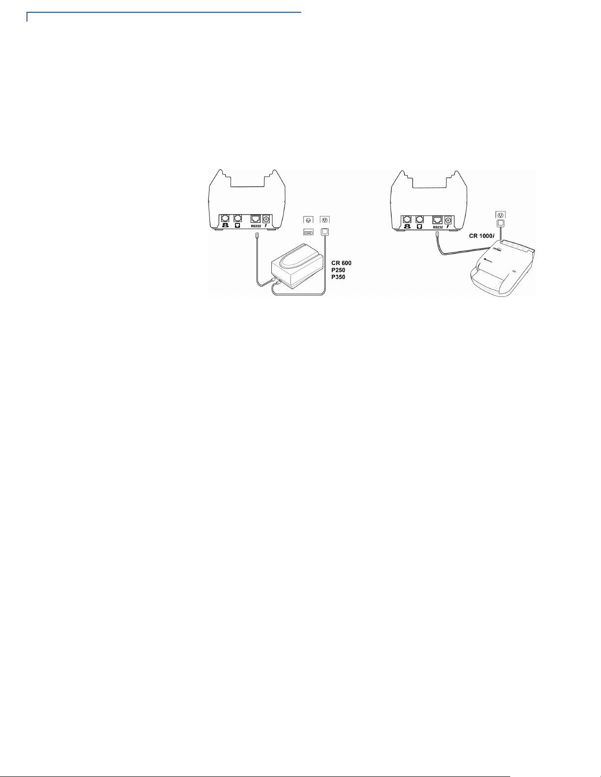
The Omni 3600 base supports two VeriFone check readers: CR 600 and
CR 1000i. Contact your VeriFone representative or visit the online store at
www.verifone.com for information on these devices. Figure 28 provides an
example of a peripheral connection.
Figure 28 Example Peripheral Connections
Although the Omni 3600 has an internal thermal printer (see Paper Installation), it
may be convenient to print larger print runs (for example, daily or weekly reports)
to an external printer. The Omni 3600 base supports three VeriFone external
printers: P250, P350, and P900. Contact your VeriFone representative or visit the
online store at www.verifone.com for information on these devices. External
printer connections are through the same port as check readers (see Figure 28).
30 OMNI 3600 INSTALLATION GUIDE
Maintenance
CHAPTER 4
This section discusses maintenance of the Omni 3600 terminal and Omni 3600
base.
Cleaning
CAUTION
Teminal and Base
Contacts
CAUTION
Card Readers
For normal dirt, use a clean cloth slightly dampened with water and a drop or two
mild soap. For stubborn stains, use alcohol or an alcohol-based cleaner.
Never use thinner, acetone, trichloroethylene, or ketone-based
solvents — these chemicals can deteriorate plastic or rubber parts.
Do not spray cleaners or other solutions directly onto the keypad or
display.
Gently swab the contacts with alcohol or contact cleaner to remove dirt. It is
important that the exposed contacts in the docking cradle of the base stay clean
and unbent.
Avoid touching the contacts in the raised area in the center of the base and the
recessed area on the terminal. Finger oils tarnish contacts, causing bad
connections. If the battery charge state or terminal power LEDs do not light when
the terminal is docked or there is a high occurrence of bad or incomplete data
transfers, clean the contacts.
The magnetic and smart card readers require no regular maintenance. For card
reader service, contact your VeriFone distributor or service provider.
CAUTION
Do not attempt to clean the card readers. Doing so may void your warranty.
OMNI 3600 INSTALLATION GUIDE 31

MAINTENANCE
Cleaning
32 OMNI 3600 INSTALLATION GUIDE
Troubleshooting
CHAPTER 5
VeriFone follows stringent quality control standards in the manufacture of
Omni 3600 terminals. Each unit that leaves the factory receives numerous tests to
ensure quality and reliable operation. However, should you encounter a problem
in operation, read this section for possible causes and solutions.
NOTE
Troubleshooting
Guidelines
NOTE
Terminal Does Not
Start
The Omni 3600 terminal comes equipped with tamper-evident labels. Do not,
under any circumstance, attempt to disassemble the terminal.
The troubleshooting guidelines provided in the following section identify various
problems and suggest appropriate corrective actions. If you have problems
operating your Omni 3600 terminal, please read through these troubleshooting
examples. If the problem persists or if it is not described below, contact your local
VeriFone representative for assistance.
During normal, day-to-day operation of your Omni 3600 terminal, it is possible that
minor malfunctions may occur. Here are some examples of possible problems
and steps you can take to resolve them.
Perform only those adjustments or repairs specified in this guide. For all other
services, contact your local VeriFone distributor or service provider. Service
conducted by parties other than authorized VeriFone representatives may void
the product warranty.
• Ensure that the smart battery charge state is not below the critically low level.
• Recharge or replace the smart battery.
Terminal Does Not
Turn Off
Terminal Display
Does Not Show
Correct or
Readable
Information
• Ensure that you pressed the ENTER/ON key for approximately 3 seconds,
until the unit lit up.
The Omni 3600 terminal will not shut off or go into sleep mode while docked in the
Omni 3600 base. You must turn off a docked Omni 3600 terminal manually or
remove the Omni 3600 terminal from the Omni 3600 base to allow it to enter sleep
mode.
• Recharge or replace the battery.
• Dock the Omni 3600 terminal in a powered Omni 3600 base (if you have one)
to see if this clears the problem, which points to a discharged battery.
If the problem persists, contact your local VeriFone representative for assistance.
OMNI 3600 INSTALLATION GUIDE 33

TROUBLESHOOTING
Troubleshooting Guidelines
Smart Battery Will
Not Charge
NOTE
NOTE
The smart battery must initially receive a full charge and then full discharge to
calibrate its full charge capacity. This operation is performed at manufacture;
however, it is recommended that the battery receive a full charge/discharge once
a year.
Allow the Omni 3600 terminal to remain connected to the power pack
for a minimum of 2 hours, maximum of 4 hours to ensure the battery
receives a full charge.
Conserve battery power by turning the Omni 3600 terminal off when
not in use. If the terminal is not to be used for several days, remove the
battery from the terminal as it continues to discharge even when the
terminal is turned off.
To discharge the smart battery, run the unit until the smart battery is fully drained.
The Omni 3600 terminal automatically shuts off when the smart battery reaches
the critically low charge state. If this occurs, the smart battery must recharge a
minimum of 1/2 hour before it can power the terminal. It make take several
recharge attempts to reset the safety circuit when charging a smart battery that
has reached a critically low charge state.
Telephone Line
Connection Does
Not Work Properly
Printer Does Not
Work
• Check the telephone line cord-to-base connections, and all telephone
connections.
• Check the telephone line cord.
• If you are using a pass-through (Telset) connection, check that the telephone
handset is seated properly in its cradle. Also, check the line using another
telephone base unit. If the other telephone works, have the defective
telephone repaired or replaced.
• If you are using a direct (Telco) connection, check the Telco cable by plugging
it into a working telephone and listening for a dial tone. If this test does not
work, replace the Telco cable.
• If it is determined that the telephone line is dead, contact your local telephone
company to check the status of the line.
If the problem persists, contact your local VeriFone representative for assistance.
• Check battery status. The printer will not print if there is an insufficient charge
remaining in the battery to complete the print operation.
• Check if the printer is out of paper and that the roll is properly installed. Open
the paper roll cover and install a new roll of printer paper or ensure that the roll
is feeding from the bottom.
• Verify that the printer roller and paper roll dust cover are properly installed.
If the problem persists, contact your local VeriFone representative for assistance.
34 OMNI 3600 INSTALLATION GUIDE

TROUBLESHOOTING
Troubleshooting Guidelines
Serial Port Does
Not Work
Terminal Does Not
Process
Transactions
• Check the power cable connection.
• Ensure the outlet has power.
• The serial port on the back panel of the Omni 3600 base is identified by the
“RS232” icon. Check that the device connected to the serial port has power
and is functioning properly. If possible, perform a self-test on the device in
question.
• The cable connecting the optional device to the Omni 3600 base serial port
may be defective. Try a different serial cable.
If the problem persists, contact your local VeriFone representative for assistance.
There are several possible reasons why the terminal may not be processing
transactions. Use the following steps to troubleshoot failures.
Step 1: Check the magnetic card reader
• Perform a test transaction using several different magnetic stripe cards to
ensure the problem is not a defective card.
• Ensure that you are swiping cards properly. With the Omni 3600 card reader,
the black, magnetic stripe on the card should face down, away from the
keypad.
• Process a transaction manually using the keypad instead of the card reader. If
the manual transaction works, the problem may be a defective card reader.
Contact your VeriFone distributor or service provider.
• If the manual transaction does not work, proceed to Step 4.
Step 2: Check the smart card reader
• Perform a test transaction using several different smart cards to ensure the
problem is not a defective card.
• Ensure that the card is inserted correctly. The chip on the card should be
facing up and inward.
• Ensure the MSAM cards are properly inserted in the cardholders and the
cardholders are properly secured (see Install/Replace MSAM Cards).
• If the manual transaction does not process, proceed to Step 4.
Step 3: Check the signal strength on-screen (SoftPay)
• Signal-strength indicator displays at least one bar to indicate connectivity to
radio network.
• Check antenna connection and orientation.
• Ensure that the radio has been activated by your service provider.
Step 4: Check the telephone line
• Connect to a working telephone and check for a dial tone. If there is no dial
tone, replace the Telco cable.
O
MNI 3600 INSTALLATION GUIDE 35

TROUBLESHOOTING
Troubleshooting Guidelines
• If the problem appears to be with the telephone line, check with the party you
are trying to call to see if their system is operational. If they are not
experiencing difficulties with their line, contact the telephone company and
have your line checked.
• If the telephone line works, contact your local VeriFone representative for
assistance.
Keypad Does Not
Respond
• Check the display panel. If it displays the wrong character or nothing at all
when you press a key, follow the steps outlined in Terminal Display Does Not
Show Correct or Readable Information.
• If pressing a function key does not perform the expected action, refer to the
user documentation for that application to ensure you are entering data
correctly.
If the problem persists, contact your local VeriFone representative for assistance.
36 OMNI 3600 INSTALLATION GUIDE

VeriFone Service and Support
For Omni 3600 terminal or Omni 3600 base problems, contact your local
VeriFone representative or service provider.
For Omni 3600 product service and repair information:
• United States: VeriFone Support Services, 1-800-837-4366, Monday–Friday,
8 A.M.–8 P.M. eastern time
• International: Contact your local VeriFone representative
For Omni 3600 supplies:
• VeriFone online store at www.store.verifone.com
• United States: VeriFone Support Services, 1-800-837-4366, Monday–Friday,
8 A.M.–8 P.M. eastern time
• International: Contact your local VeriFone representative
CHAPTER 6
Return a
Terminal, Base,
or Smart
Battery
NOTE
Before returning an Omni 3600 terminal, Omni 3600 base, or smart battery to
VeriFone, you must obtain a Merchandise Return Authorization (MRA) number.
The following procedure describes how to return one or more Omni 3600
terminals, Omni 3600 bases, or smart batteries for repair or replacement (U.S.
customers only):
International customers, please contact your local VeriFone representative for
assistance with your service, return, or replacement.
1 Gather the following information from the printed labels on each Omni 3600
terminal (Figure 29), Omni 3600 base (Figure 30), and smart battery
(Figure 31) you are returning:
• Product ID, including the model and part number. For example,
“OMNI 3600” and “PTID XXXXXXXX” (if your terminal includes this
number)
• Serial number (S/N XXX-XXX-XXX)
2 Within the United States, call VeriFone toll-free at 1-800-837-4366.
3 Select the MRA option from the automated message. The MRA department is
open Monday–Friday, 8 A.M.–8 P.M., eastern time.
4 Give the MRA representative the information gathered in Step 1.
OMNI 3600 INSTALLATION GUIDE 37

VERIFONE SERVICE AND SUPPORT
Return a Terminal, Base, or Smart Battery
If the list of serial numbers is long, you can fax the list, along with the
information gathered in Step 1, to the MRA department. Include a telephone
number where you can be reached and your fax number.
Please print clearly to the attention of the “VeriFone MRA Dept.” and send
your fax to 727-953-4172 (U.S.). You will be issued an MRA number and the
fax returned to you.
NOTE
One MRA number must be issued for each Omni 3600 terminal or Omni 3600
base you return to VeriFone, even if you are returning several of the same model.
5 Describe the problem and provide the shipping address to return the repaired
or replacement unit.
6 Keep a record of the following items:
• Assigned MRA number(s)
• VeriFone serial number assigned to the Omni 3600 terminal, Omni 3600
base, or smart battery you are returning for service or repair (terminal
serial numbers are located on the inside of the smart battery compartment;
base serial numbers on the bottom of the unit; smart battery serial
numbers on the side of the battery)
• Shipping documentation, such as airbill numbers used to trace the
shipment
• Model(s) returned (model numbers are located on the VeriFone label on
the bottom of the Omni 3600 terminal or Omni 3600 base)
Figure 29 Omni 3600 Terminal Information Label Locations
38 OMNI 3600 INSTALLATION GUIDE
MOBITEX RADIO
MODULE LABEL
GSM RADIO
MODULE
LABEL
PRODUCT INFORMATION
SERIAL NUMBER
LABEL
LABEL
PTID LABEL

VERIFONE SERVICE AND SUPPORT
Return a Terminal, Base, or Smart Battery
PRODUCT
INFORMATION LABEL
SERIAL NUMBER
LABEL
Figure 30 Omni 3600 Base Information Label Locations
SERIAL NUMBER
LABEL
PRODUCT INFORMATION
LABEL
Figure 31 Smart Battery Information Label Locations
O
MNI 3600 INSTALLATION GUIDE 39

VERIFONE SERVICE AND SUPPORT
Return a Terminal, Base, or Smart Battery
40 OMNI 3600 INSTALLATION GUIDE
Specifications
CHAPTER 7
This section provides information on the power requirements, environmental
conditions that the units can be subjected to, and unit dimensions.
Power
Requirements
Environmental
DC power (all Omni 3600 terminals and Omni 3600 bases): DC: 19VDC; 3.16A
DC power pack (all Omni 3600 terminals and Omni 3600 bases):
• Input: 100–240 V ~ (100–240VAC); 50–60 Hz; 1.5A
• Output: 19VDC; 3.16A
Barrel connector polarity (all Omni 3600 terminals and Omni 3600 bases):
Omni 3600 terminal:
• Operating temperature: 0° to + 50° C (32° to 122° F)
• Storage temperature: – 20° to + 70° C (0° to 158° F)
• Relative humidity: 15% to 90%; no condensation
Omni 3600 base:
• Operating temperature: 0° to 55° C (32° to 131° F)
• Storage temperature: – 40° to + 70° C (–40° to 158° F)
• Relative humidity: 15% to 90%; no condensation
Omni 3600
Terminal
Dimensions
Weight • Terminal weight: 568 g (1.25 lb)
• Height: 69 mm (2.72 inches)
• Width: 95 mm (3.74 inches)
• Length: 220 mm (8.64 inches)
• with battery installed: 681 g (1.5 lb)
• with battery and paper roll installed: 710 g (1.56 lb)
• Shipping weight: 1264 g (2.78 lb): The shipping weight for the Omni 3600
terminal includes: shipping carton, one terminal, power pack and cable, one
smart battery, paper roll, and one Quick Installation Guide.
OMNI 3600 INSTALLATION GUIDE 41

SPECIFICATIONS
Omni 3600 Base Dimensions
Omni 3600
Base
Dimensions
Weight • Base station weight: 378 g (0.83 lb)
• Height: 88.9 mm (3.5 inches)
• Width: 95.25 mm (3.75 inches)
• Length: 241.3 mm (9.5 inches)
• Shipping weight: 498 g (1.098 lb): The shipping weight for the Omni 3600
base station includes: shipping carton, one base station, one Telco cable, and
one Quick Installation Guide.
42 OMNI 3600 INSTALLATION GUIDE

Accessories and Documentation
This sections lists accessories and documentation available for the Omni 3600.
When ordering, please refer to the part number in the left column.
CHAPTER 8
How to Order
Omni 3600
Terminal
Download Cables
and Adapters
Cables for
Optional
Peripherals
• VeriFone Online Store at www.store.verifone.com
• United States: VeriFone Customer Development Center, 1-800-837-4366,
Monday–Friday, 8 A.M.–8 P.M., eastern time
• International: Contact your local VeriFone representative
This section presents accessory and part replacement ordering information for the
Omni 3600 terminal. See VeriFone Service and Support for product service and
repair information.
05651-xx MOD10-MOD10 (base station-to-base station)
26263-xx 02xxx MOD10-PC DB25F (base station-to-PC)
26264-xx 02xxx MOD10-PC DB9F (base station-to-PC)
22536-01 MOD10 adapter (terminal-to-terminal/PC/telephone)
07041-xx MOD10-MDIN9 (CR 600/CR 1000i check readers)
Base Station
Telco Cable
Smart Battery
Power Pack
P096-201-00 Base station
00124-17 2.1-m (7’) telephone line cord, black color, with modular RJ11-type
connectors
22044-02 12V battery pack
Contact your local VeriFone distributor to determine which power pack fits your
needs.
22161-01 DC power pack (universal)
21973-01 Power cable (U.S.)
OMNI 3600 INSTALLATION GUIDE 43

ACCESSORIES AND DOCUMENTATION
Omni 3600 Base
Thermal Printer
Paper
Antenna
VeriFone Cleaning
Kit
Omni 3600
Base
Download Cables
CRM0043 Standard-grade thermal printer paper, 57-mm (2.25”) width, 7.62-m
(25’) length; single roll
Contact your VeriFone distributor to determine the exact antenna for your
Omni 3600 terminal.
22066-XX Replacement antenna.
02746-01 Cleaning kit
P096-201-00 Base, U.S., 14.4 Kbps modem
P096-203-00 Base, generic 14.4 Kbps modem
05651-xx MOD10-MOD10 (base-to-base)
26263-xx 02xxx Mod 10-PC DB25F (base-to-PC)
26264-xx 02xxx Mod 10-PC DB9F (base-to-PC)
Cables for
Optional
Peripherals
Telephone Line
Cord
Documentation
07041-xx MOD10-Mini DIN9 (CR 600/CR 1000i check readers; P250/P355/P900
external printers)
00124-17 2.1-meter (7-foot) telephone line cord, black color, with modular RJ11-type
connectors
22377 Omni 3600 Quick Installation Guide
22378 Omni 3600 Base Station Quick Installation Guide
22060 Omni 3600 Installation Guide
19733 Verix Operating System Programmer’s Manual
44 OMNI 3600 INSTALLATION GUIDE

VeriFone, Inc.
2455 Augustine Drive
Santa Clara CA 95054-3002
Tel: 800-VeriFone (
837-4366)
www.verifone.com
VERIX
OPERATING
ENVIRONMENT
SOFTPAY
E-PAYMENT
APPLICATION
VERIX
DEVELOPER
TOOLKIT
DEVELOPM ENT
TOOLS
VERISHIELD
SECURITY
ARCHITECTURE
Omni 3600
Installation Guide
OMNI 37XX
HAND-OVER-COUNTER
MULTI-APPLICATION
APPLIANCES
OMNI 33XX
MULTI-APPLICATION
APPLIANCES
OMNI 3600
HAND-HELD
RADIO MODEM
APPLIANCES
VERICENTRE
APPLIANCE
MANAGEMENT
SUITE
Part Number 22060, Revision D
 Loading...