

Page 1
e355
Installation Guide
C
V
O
E
N
R
F
F
I
DE
I
R
O
VIS
E
N
N
E
T
O
I
I
N
A
A
L
2
.
Verifone Part Number DOC087-063-EN-A, Revision A.2
Page 2

e355 Installation Guide
WARNING
© 2015 Verifone, Inc.
All rights reserved. No part of the contents of this document may be reproduced or transmitted in any form without the written
permission of Verifone, Inc.
The information contained in this document is subject to change without notice. Although Verifone has attempted to ensure the
accuracy of the contents of this document, this document may include errors or omissions. The examples and sample programs are
for illustration only and may not be suited for your purpose. You should verify the applicability of any example or sample p rogram
before placing the software into productive use. This document, including without limitation the examples and software programs, is
supplied “As-Is.”
Verifone and the Verifone logo are registered trademarks of Verifone. Other brand names or trademarks associated with Verifone’s
products and services are trademarks of Verifone, Inc.
All other brand names and trademarks appearing in this manual are the property of their respective holders.
Comments? Please e-mail all comments on this document to your local Verifone Support Team.
The e355 uses a lithium-ion rechargeable battery. Do not dispose the e355 in a fire.
Lithium-ion polymer batteries must be recycled or disposed of properly. Do not dispose
lithium-ion polymer batteries in municipal waste sites.
C
V
O
E
N
R
F
F
I
DE
I
R
O
VIS
E
N
N
E
T
O
I
I
N
A
A
L
2
.
Verifone, Inc.
2099 Gateway Place, Suite 600
San Jose, CA, 95110 USA
1-800-VERIFONE
www.verifone.com
Verifone Part Number DOC087-063-EN-A, Revision A.2
Page 3

CONTENTS
PREFACE . . . . . . . . . . . . . . . . . . . . . . . . . . . . . . . . . . . . . . . 5
Audience. . . . . . . . . . . . . . . . . . . . . . . . . . . . . . . . . . . . . . . . . . . . . . . . . . . . . . . . 5
Organization. . . . . . . . . . . . . . . . . . . . . . . . . . . . . . . . . . . . . . . . . . . . . . . . . . . . . 5
Related Documentation . . . . . . . . . . . . . . . . . . . . . . . . . . . . . . . . . . . . . . . . . . . . 5
Conventions and Acronyms . . . . . . . . . . . . . . . . . . . . . . . . . . . . . . . . . . . . . . . . . 6
CHAPTER 1
Device Overview Features and Benefits . . . . . . . . . . . . . . . . . . . . . . . . . . . . . . . . . . . . . . . . . . . . . 8
Exceptional Ease of Use . . . . . . . . . . . . . . . . . . . . . . . . . . . . . . . . . . . . . . . . . 8
Performance and Durability . . . . . . . . . . . . . . . . . . . . . . . . . . . . . . . . . . . . . . 8
Security. . . . . . . . . . . . . . . . . . . . . . . . . . . . . . . . . . . . . . . . . . . . . . . . . . . . . . 8
Contactless Capability . . . . . . . . . . . . . . . . . . . . . . . . . . . . . . . . . . . . . . . . . . 8
N
O
CHAPTER 2
Device Setup Usage Guidelines. . . . . . . . . . . . . . . . . . . . . . . . . . . . . . . . . . . . . . . . . . . . . . . . 10
Environmental Factors . . . . . . . . . . . . . . . . . . . . . . . . . . . . . . . . . . . . . . . . . 10
R
Personal Security Considerations. . . . . . . . . . . . . . . . . . . . . . . . . . . . . . . . . 10
E
Electrical Considerations . . . . . . . . . . . . . . . . . . . . . . . . . . . . . . . . . . . . . . . 10
Unpacking the Shipping Carton . . . . . . . . . . . . . . . . . . . . . . . . . . . . . . . . . . . . . 10
V
Examining e355 Device Features. . . . . . . . . . . . . . . . . . . . . . . . . . . . . . . . . . . . 11
N
O
C
Examining e355 Frame Features. . . . . . . . . . . . . . . . . . . . . . . . . . . . . . . . . . . . 19
F
Front View. . . . . . . . . . . . . . . . . . . . . . . . . . . . . . . . . . . . . . . . . . . . . . . . . . . 11
Back View. . . . . . . . . . . . . . . . . . . . . . . . . . . . . . . . . . . . . . . . . . . . . . . . . . . 13
Installing/Replacing an MSAM Card. . . . . . . . . . . . . . . . . . . . . . . . . . . . . . . 13
Manually Starting and Resetting the e355 . . . . . . . . . . . . . . . . . . . . . . . . . . 15
Connecting the e355 to a Power Source or a Host Computer . . . . . . . . . . . 15
Color Behavior . . . . . . . . . . . . . . . . . . . . . . . . . . . . . . . . . . . . . . . . . . . . . . . 16
Using the Smart Card Reader. . . . . . . . . . . . . . . . . . . . . . . . . . . . . . . . . . . . 17
Using the Magnetic Stripe Reader . . . . . . . . . . . . . . . . . . . . . . . . . . . . . . . . 17
Using the CTLS Reader . . . . . . . . . . . . . . . . . . . . . . . . . . . . . . . . . . . . . . . . 18
Using the Barcode Reader . . . . . . . . . . . . . . . . . . . . . . . . . . . . . . . . . . . . . . 18
Front View. . . . . . . . . . . . . . . . . . . . . . . . . . . . . . . . . . . . . . . . . . . . . . . . . . . 19
Back View. . . . . . . . . . . . . . . . . . . . . . . . . . . . . . . . . . . . . . . . . . . . . . . . . . . 19
Attaching the e355 Device to the e355 Frame . . . . . . . . . . . . . . . . . . . . . . . 20
Attaching a Tablet to the e355 Frame. . . . . . . . . . . . . . . . . . . . . . . . . . . . . . 20
Connecting the e355 Frame to a Power Source. . . . . . . . . . . . . . . . . . . . . . 21
F
I
DE
I
R
N
VIS
E
E
T
O
I
I
N
A
A
L
6
.
CHAPTER 3
Specifications Power . . . . . . . . . . . . . . . . . . . . . . . . . . . . . . . . . . . . . . . . . . . . . . . . . . . . . . . . . 23
Temperature. . . . . . . . . . . . . . . . . . . . . . . . . . . . . . . . . . . . . . . . . . . . . . . . . . . . 23
External Dimensions. . . . . . . . . . . . . . . . . . . . . . . . . . . . . . . . . . . . . . . . . . . . . . 23
CHAPTER 4
Maintenance Cleaning the Device . . . . . . . . . . . . . . . . . . . . . . . . . . . . . . . . . . . . . . . . . . . . . . 25
Smart Card Reader . . . . . . . . . . . . . . . . . . . . . . . . . . . . . . . . . . . . . . . . . . . . . . 25
E355 INSTALLATION GUIDE 3
Page 4

CONTENTS
CHAPTER 5
Verifone Service
and Support
CHAPTER 6
Troubleshooting
Guidelines
Returning a Device for Service. . . . . . . . . . . . . . . . . . . . . . . . . . . . . . . . . . . . . . 27
Accessories and Documentation . . . . . . . . . . . . . . . . . . . . . . . . . . . . . . . . . . . . 28
Accessories. . . . . . . . . . . . . . . . . . . . . . . . . . . . . . . . . . . . . . . . . . . . . . . . . . 28
Documentation . . . . . . . . . . . . . . . . . . . . . . . . . . . . . . . . . . . . . . . . . . . . . . . 28
Battery Pack Instructions . . . . . . . . . . . . . . . . . . . . . . . . . . . . . . . . . . . . . . . . . . 28
Device Does Not Start . . . . . . . . . . . . . . . . . . . . . . . . . . . . . . . . . . . . . . . . . . . . 29
Device Display Does Not Show Correct/Readable Info . . . . . . . . . . . . . . . . . . . 29
Blank Display . . . . . . . . . . . . . . . . . . . . . . . . . . . . . . . . . . . . . . . . . . . . . . . . . . . 30
Keypad Does Not Respond . . . . . . . . . . . . . . . . . . . . . . . . . . . . . . . . . . . . . . . . 30
Transactions Fail To Process. . . . . . . . . . . . . . . . . . . . . . . . . . . . . . . . . . . . . . . 30
C
V
O
E
N
R
F
F
I
DE
I
R
O
VIS
E
N
N
E
T
O
I
I
N
A
A
L
6
.
4 E355 INSTALLATION GUIDE
Page 5

This guide is your primary source of information for setting up the e355.
PREFACE
Audience
Organization
V
Related
Documentation
C
O
This guide is useful for anyone installing an e355 device. Basic descriptions of the
device features are also provided.
This guide is organized as follows:
Chapter 1, Device Overview. Provides an overview of the e355.
Chapter 2, Device Setup. Explains how to set up the e355 device. It tells you how
to select a location, establish power connection, and install the MSAM card.
Chapter 3, Specifications. Discusses power requirements and dimensions of the
e355.
N
O
Chapter 4, Maintenance. Explains how to maintain your e355.
Chapter 5, Verifone Service and Support. Provides information on how to contact
your local Verifone representative or service provider, and information on how to
order accessories or documentation from Verifone.
Chapter 6, Troubleshooting Guidelines. Provides troubleshooting guidelines,
should you encounter a problem in device installation.
To learn more about the e355, refer to the following set of documents:
R
E
F
N
e355 Certifications and Regulations Sheet VPN DOC087-061-EN
e355 Quick Installation Guide VPN DOC087-062-EN
e355 Web site
F
I
DE
I
N
VIS
E
E
T
O
I
I
N
A
A
L
6
.
www.paywaremobile.com
R
E355 INSTALLATION GUIDE 5
Page 6
PREFACE
NOTE
CAUTION
WARNING
Conventions and Acronyms
Conventions and
Acronyms
C
6 E355 INSTALLATION GUIDE
V
O
This section describes the conventions and acronyms used in this guide.
Various conventions are used to help you quickly identify special formatting.
Table 1 describes these conventions and provides examples of their use.
Table 1 Document Conventions
Convention Meaning Example
Blue Text in blue indicates terms that
are cross referenced.
Italics Italic typeface indicates book
titles or emphasis.
Courier The courier type face is used
while specifying onscreen text,
such as text that you would
enter at a command prompt, or
to provide an URL.
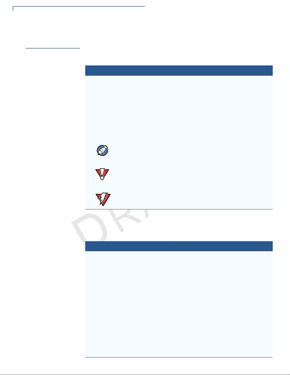
The pencil icon is used to
highlight important information.
O
N
E
A
I
See Conventions and Acronyms.
You must install a roll of thermalsensitive paper in the printer.
http://www.verifone.com
L
RS-232-type devices do not work
with the PIN pad port.
T
F
I
R
E
I
F
N
Various acronyms are used in place of the full definition. Table 2 presents
acronyms and their definitions.
Table 2 Acronym Definitions
Acronym Definitions
AC Alternating Current
ARM Acorn RISC Machine
EMV Europay MasterCard and VISA
LCD Liquid Crystal Display
LED Light Emitting Diode
NFC Near Field Communication
MRA Merchandise Return Authorization
MSAM Micromodule-Size Security Access Module
PCI Payment Card Industry
PED PIN Entry Device
PIN Personal Identification Number
SIM Subscriber Identity Module
USB Universal Serial Bus
VPN Verifone Part Number
The caution symbol indicates
possible hardware or software
failure, or loss of data.
DE
The lightning symbol is used as
a warning when bodily injury
might occur.
R
VIS
E
N
I
O
N
A
The device is not waterproof or
dustproof, and is intended for
indoor use only.
Due to risk of shock do not use the
device near water.
6
.
Page 7
Device Overview
V
CHAPTER 1
This chapter provides a brief description of the e355.
The e355 connects with various tablet devices for the next generation of PAYware
Mobile enterprise. It supports the use of the SPP standard to connect between the
e355 and tablet.
Some of the e355’s key features include: a fast processor, large memory, the
latest PCI 4.0 security, integrated 2D barcode scanner, mechanical keypad,
integrated contactless and NFC-ready, in a small most versatile form factor.
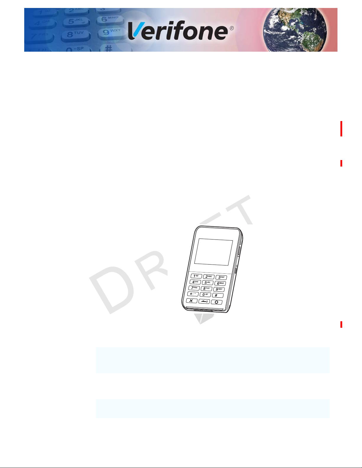
The e355 is a portable, battery-powered device designed to fit your hands
comfortably and is ideal for consumer-facing and merchant-facing retail integrated
applications. It has a removable battery that can be charged by external power
adapter through a micro-USB connector and gang charger. It also features a crisp
320 x 240 color LCD display.
R
E
F
I
I
O
DE
N
N
E
T
L
A
I
F
C
N
O
E
R
Figure 1 The e355 Unit
Key Features
• 400 MHz ARM11 processor delivers
power and usability in a convenient
“hand-over” design
• Multi-application operating
environment
• Advanced memory architecture to
meet tomorrow’s needs
VIS
I
6
.
A
N
O
• Offers unsurpassed performance on
EMV smart card transactions
• Security architecture exceeds
specifications for PCI-PED and
sophisticated file authentication
• Multiple connectivity and
contactless options
• 32-bit processing and multi-tasking
capabilities
• Spill-resistant design prevents liqui d
from entering the unit by forcing it down
and off the front of the device
E355 INSTALLATION GUIDE 7
Page 8

DEVICE OVERVIEW
Features and Benefits
Features and
Benefits
Exceptional Ease of
Use
Performance and
Durability
V
The e355 provides the right combination of features and functions including a
triple-track magnetic-stripe card reader, smart card reader, integrated PIN pad,
colored display, 2D barcode reader, and contactless/NFC support.
• The lightweight, compact, stylish, and ergonomic balance allows convenient
device hand-off to the consumer for PIN entry or other input.
• Large, well-placed, mechanical keys provide a continuity of user experience
between the e355 and the iOS, Android, or Windows device.
• Horizontal magnetic stripe card reader with an enlarged card entrance delivers
optimal card swiping and reading without the need to visually guide the card.
• The e355 size is easily able to be dropped in most pockets. An optional
hands-free holster is available that fits the server’s or clerk’s belt so that the
e355 can be quickly removed and easily handed to the customer.
• Powerful 400-mHz ARM11 processing completes transactions quickly.
• High-capacity lithium-ion polymer battery can rapidly charge and offer 10+
hours of power.
F
O
I
• Standard Micro-USB port allows for convenient product charging.
N
N
E
T
L
A
I
R
• Rounded corners to minimize breakage and drop-resistant to 3 feet on
E
concrete surfaces.
F
• 192 MB of standard memory.
DE
I
N
Security
O
C
Contactless
Capability
• PCI PED 4.x approved for debit and other PIN-based transactions
• EMV Level 1 type approval
• Tamper-resistant construction, SSL protocols, and VeriShield file
authentication
• Supports VeriShield Protect encryption implementations
VIS
I
O
N
A
.
6
E
• Advanced contactless architecture that future-proofs investment with a single
contactless interface (SingleCl), SoftSAMs, and side-by-side application
architecture.
• Large tap zone (above the keypad) that encompasses the PIN pad optimizes
user experience.
• Contactless version accepts EMV in addition to magnetic stripe contactless
payments as well as PIN-based transactions.
R
8 E355 INSTALLATION GUIDE
Page 9

Device Setup
CHAPTER 2
This chapter describes the device setup procedure. You will learn about:
• Usage Guidelines
• Unpacking the Shipping Carton
For e355 Device
C
• Examining e355 Device Features
• Installing/Replacing an MSAM Card
• Manually Starting and Resetting the e355
• Connecting the e355 to a Power Source or a Host Computer
• Color Behavior
• Using the Smart Card Reader
V
• Using the Magnetic Stripe Reader
• Using the CTLS Reader
O
• Using the Barcode Reader
R
E
F
N
F
I
I
O
DE
N
N
E
T
L
A
I
.
N
A
For e355 Frame
• Examining e355 Frame Features
• Attaching the e355 Device to the e355 Frame
• Attaching a Tablet to the e355 Frame
• Connecting the e355 Frame to a Power Source
R
VIS
E
I
O
6
E355 INSTALLATION GUIDE 9
Page 10

DEVICE SETUP
CAUTION
Usage Guidelines
Usage
Guidelines
Environmental
Factors
Personal Security
Considerations
V
Use the following guidelines when using your e355.
• Select a flat support surface, such as a countertop or table, to keep the device
safe in between uses.
• Do not use the device where there is high heat, dust, humidity, moisture, or
caustic chemicals or oils.
• Keep the device away from direct sunlight and anything that radiates heat,
such as a stove or motor.
• Do not use the device outdoors.
The device is not waterproof or dustproof, and is intended for indoor use only.
Any damage to the unit from exposure to rain or dust may void any warranty.
N
O
The e355 is a handover device. Always exercise extreme caution when
conducting transactions especially during PIN entry.
R
• Hand the e355 directly to the cardholder for PIN entry.
E
• Encourage the cardholder to hold the e355 close to avoid others from seeing
the information entered.
F
F
I
DE
I
N
E
T
L
A
I
Electrical
Considerations
O
C
Unpacking the
Shipping Carton
To unpack the
shipping carton
N
• Avoid using this product during electrical storms.
• Avoid locations near electrical appliances or other devices that cause
excessive voltage fluctuations or emit electrical noise (for example, air
conditioners, electric motors, neon signs, high-frequency or magnetic security
devices, or computer equipment).
• Do not use the device near water or in moist conditions.
VIS
I
O
N
E
Open the shipping carton and carefully inspect its content s for possible t ampering
or shipping damage. The e355 is a secure product and any tampering may cause
the device to cease to function properly.
1 Remove and inspect the following items:
• e355 unit
• USB to Micro-USB cable
2 Remove all plastic wrapping from the unit and other components.
R
A
.
6
10 E355 INSTALLATION GUIDE
Page 11
DEVICE SETUP
CAUTION
NOTE
NOTE
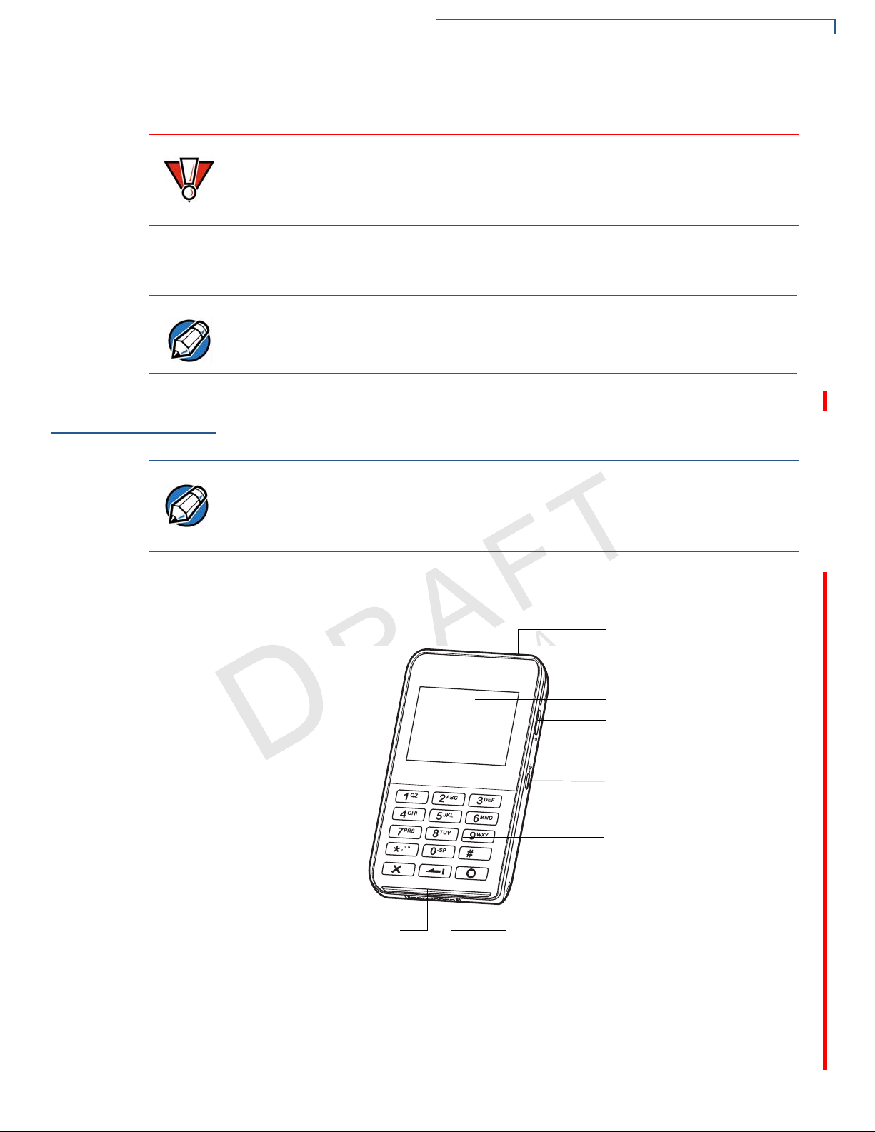
LCD DISPLAY
KEYPAD
2D IMAGER
BARCODE BUTTON
POWER LED INDICATOR
MICRO-USB PORT
DOCKING CONNECTOR
MAGNETIC STRIPE READER
SMART CARD READER
Examining e355 Device Features
3 Remove the clear protective film from the unit.
Do not use a unit that has been damaged or tampered with. The e355 comes
equipped with tamper-evident labels. If a label or component appears damaged
or if the device appears to have been opened, please notify the shipping
company and your Verifone representative or service provider immediately.
4 Save the shipping carton and packing material for future repacking or moving
the device.
Charge the e355 device for eight hours before initial use.
Examining e355
Device Features
Front View
C
Before you continue the installation process, familiarize yourself with the features
of the e355. (See
Figure 3 and Figure 2)
N
O
Verifone ships variants of the e355 for different markets. Your device may have a
different configuration. The following devices may or may not be present: a CTLS
reader, smart card reader, or a barcode scanner. However, the basic processes
described in this guide remain the same, regardless of device configuration.
V
The front panel includes the following features:
R
E
F
F
I
DE
I
N
E
T
L
A
I
N
O
E
R
VIS
I
O
N
A
.
6
Figure 2 e355 Device Features (Front View)
• A 320 x 240 pixel color LCD Display
• Barcode Buttons located on both sides of the e355 to activate the 2D imager
for scanning barcodes. (See
Using the Barcode Reader)
E355 INSTALLATION GUIDE 11
Page 12

DEVICE SETUP
CAUTION
Examining e355 Device Features
• A Power LED Indicator beside the Micro-USB port indicates the e355
device’s operational state.
• A Micro-USB port located on the right side for data connection and power
charging. You can also use this connect the e355 to a computer using a
standard USB to Micro-USB cable (VPN CBL000-049-01-A). (See
the e355 to a Power Source or a Host Computer)
• Two types of keys on the mechanical keypad:
a A 12-key keypad
b Three color-coded function keys below the keypad
Do NOT paste anything on the keypad surface to avoid malfunction.
Connecting
C
V
O
E
• A Docking Connector at the bottom of the device to connect to the optional
e355 Frame.
• A Smart Card Reader to process smart card transactions (See Using the
Smart Card Reader)
R
• A Magnetic Stripe Reader, for performing debit or credit card transactions
E
(See
F
I
I
Using the Magnetic Stripe Reader).
O
DE
N
I
T
N
L
A
F
• A 2D Imager located on top of the device for scanning barcodes; an audible
N
“beep” indicates a successful scan. (See
• LEDs that act as CTLS activity, system power, and charging indicators (See
Color Behavior)
I
N
O
• A CTLS functionality for contactless payments (See Using the CTLS
Reader)
VIS
E
R
Using the Barcode Reader)
6
.
A
12 E355 INSTALLATION GUIDE
Page 13

DEVICE SETUP
BATTERY COMPARTMENT COVER
MSAM COMPARTMENT
BARCODE BUTTON
NOTE
CAUTION
NOTE
Examining e355 Device Features
Back View
V
O
C
The front panel includes the following features:
O
E
N
I
L
A
T
F
I
Figure 3 e355 Device Features (Back View)
• A Battery Compartment Cover. Remove the cover to access the removable
R
E
battery and the MSAM compartment.
DE
I
N
F
• An MSAM (Micromodule-Size Security Access Module) Compartment to
N
support stored-value card programs or other merchant card requirements.
.
6
(See
Installing/Replacing an MSAM Card)
A
The MSAM compartment is located inside the battery compartment. Remove the
battery to display the access the compartment.
I
O
N
Installing/Replacing
• Barcode Buttons located on both sides of the e355 to activate the 2D imager
for scanning barcodes. (See
When you first receive your e355, you may need to install an MSAM card or you
an MSAM Card
may need to replace an old card.
Observe standard precautions when handling electrostatically sensitive devices.
Electrostatic discharges can damage this equipment. V erifone recommends using
a grounded anti-static wrist strap.
Not all applications require the use of an MSAM card.
VIS
E
R
Using the Barcode Reader)
E355 INSTALLATION GUIDE 13
Page 14

DEVICE SETUP
NOTE
NOTE
05,,
+
-
05,,
+
-
05,,
+
-
05,,
+
-
Examining e355 Device Features
To install/replace
MSAM
V
1 Unplug any cables or chargers from the e355.
2 Remove the screw from the battery cover.
3 Slide the cover outwards, away from the device.
4 Remove the battery by gently pulling the plastic tab to access the MSAM
compartment. The MSAM compartment is located on the left side of the
battery compartment.
5 Insert the MSAM card with the gold contacts facing up.
Make sure that the MSAM card is fully inserted to be able to re-insert the battery.
6 Re-insert the battery by aligning the gold contacts in the battery with the pins
on the e355 device.
N
O
E
L
A
I
T
The plastic tab attached to the ba ttery allows you to easily remove the battery from
the compartment. Make sure that the plastic tab is still visible after insertion.
I
F
N
R
E
DE
I
F
N
O
C
O
I
VIS
E
Figure 4 Inserting an MSAM Card
7 Place the battery cover back and tighten the screw.
Figure 5 Returning the battery cover
R
N
A
.
6
14 E355 INSTALLATION GUIDE
Page 15

DEVICE SETUP
CAUTION
NOTE
Examining e355 Device Features
Manually Starting
and Resetting the
e355
Connecting the e355
to a Power Source
or a Host Computer
To Connect the e355
to a Wall-mount
Charger
V
To turn on the e355, press and hold the Enter key for at least five seconds.
The Reset Button is located between the right Barcode Button and Power LED
Indicator.
The Reset Button resets the device to its initialized state. NEVER use the Reset
button unless instructed by a Verifone support representative.
Plug the wall-mount charger to an external power source and connect it to the
e355 to charge the device. You can also connect the e355 to a computer to
synchronize data and/or charge the device.
Charge the e355 device for eight hours before initial use.
N
1 Plug the Verifone-certified wall-mount charger into a wall outlet or powered
surge protector.
2 Insert the Micro-USB cable into the port located on the side of the e355.
R
E
F
I
I
O
N
DE
E
T
L
A
I
F
C
N
O
6
.
A
N
O
I
VIS
E
R
Figure 6 Connecting the e355 to a Wall-mount Charger
E355 INSTALLATION GUIDE 15
Page 16

DEVICE SETUP
Examining e355 Device Features
To Connect the e355
to a Host Computer
via Micro-USB
Color Behavior
V
Sleep
Battery
Low
Extremely
1 Connect the Micro-USB cable into the port located on the side of the e355.
2 Connect the other end of the Micro-USB cable into the host computer’s USB
port.
E
N
Figure 7 Connecting the e355 to a Host Computer
O
F
F
I
DE
I
Battery
Charging
The following table shows the behavior of the LEDs during various system power
R
states.
E
Battery
N
Low
N
Charging
Timer
Fault
I
T
Normal
Operation
L
A
LED Behavior
Y Green, blinks every 4 seconds
C
O
Y Red, 1Hz rate, 50% duty cycle
A
N
O
I
Y Red, 4Hz rate, 50% duty cycle
VIS
6
.
(Battery low condition: battery
voltage <3.7V)
E
R
Y Orange, 1Hz rate, 50% duty cycle
Y Orange, on continuously
Y Green, on continuously
(Battery extremely low condition:
battery voltage <3.6V)
LEDs are turned OFF when
charging the e355 on a gang
charger
16 E355 INSTALLATION GUIDE
Page 17

DEVICE SETUP
Examining e355 Device Features
Using the Smart
Card Reader
To conduct a smart
card transaction
V
Using the Magnetic
Stripe Reader
O
C
To conduct a credit/
debit card transaction
The smart card transaction procedure may vary from one application to another.
Verify the procedure with your application provider before performing a smart card
transaction.
1 Position the smart card with the contacts facing in the same direction as the
keypad.
2 Insert the card into the reader slot in a smooth, continuous motion until it seats
firmly.
O
E
N
I
L
A
T
F
I
Figure 8 Inserting a Smart Card
3 Wait for the application to indicate a completed transaction before removing
R
E
F
the card. Premature card removal invalidates the transaction.
DE
I
N
N
Use the magnetic stripe reader to perform credit and debit card transactions.
A
1 Position the card with the magnetic stripe facing backwards.
O
2 To ensure a proper read of the magnetic swipe card, insert the magnetic card
from the top of the device, as shown in
VIS
E
I
N
Figure 9.
R
.
6
Figure 9 Using Magnetic Stripe Card
3 Swipe the card through the magnetic card reader.
E355 INSTALLATION GUIDE 17
Page 18

DEVICE SETUP
IMAGE PLACEHOLDER
ACTUAL ILLUSTRATION TO FOLLOW
IMAGE PLACEHOLDER
ACTUAL ILLUSTRATION TO FOLLOW
NOTE
Examining e355 Device Features
Using the CTLS
Reader
Using the Barcode
Reader
E
V
The e355 supports contactless credit or debit card transactions. To perform a
contactless transaction, gently tap the card or hold the card against the su rface of
the contactless antenna, located above the keyp ad and LCD with a CTLS symbol.
Figure 10 Using the CTLS reader
The Barcode buttons located on either side of the e355, activate the barcode
reader (see
Figure 3). Press either button to scan barcodes.
O
E
N
I
L
A
T
F
Figure 11 Using the Barcode Reader
R
When activated, do not point the barcode reader directly at a person to avoid
unnecessary harm or injury.
Use of controls or adjustments or performance of procedures other than those
N
specified herein may result in hazardous radiation exposure.
I
DE
I
F
N
C
O
R
VIS
E
I
O
N
A
.
6
18 E355 INSTALLATION GUIDE
Page 19

DEVICE SETUP
IMAGE PLACEHOLDER
ACTUAL ILLUSTRATION TO FOLLOW
NOTE
IMAGE PLACEHOLDER
ACTUAL ILLUSTRATION TO FOLLOW
NOTE
Examining e355 Frame Features
Examining e355
Frame Features
Front View
V
O
C
Back View
The following section discusses the features of the e355 Frame. (See Figure 3
and Figure 2)
The front panel includes the following features:
Figure 12 e355 Frame (Front View)
• A Locking Screw to secure the e355 device to the Frame.
The locking screw is captive, which means that it cannot be fully removed from
the slot.
N
O
E
L
A
I
T
• An Eject Button below the Locking Screw to easily remove the e355 device
from the Frame.
I
F
N
R
• A Micro-USB cover. Remove the cover to access the e355 device’s Micro-
E
USB port for power and data connection.
• Barcode Buttons located on both sides to activate the e355 device’s 2D
N
• A Docking Connector to connect to the e355 device.
• A Power Connector to charge the e355 and tablet devices.
The front panel includes the following features:
F
imager for scanning barcodes.
DE
I
I
O
N
A
.
6
VIS
E
R
Figure 13 e355 Frame (Back View)
• A Removable Module that serves as a locking attachment for the tablet and
the e355
• A Locking Screw on the upper left side of of the e355 Frame back panel to
secure the tablet and the Removable Module.
The locking screw is captive, which means that it cannot be fully removed from
the slot.
frame.
E355 INSTALLATION GUIDE 19
Page 20

DEVICE SETUP
NOTE
Examining e355 Frame Features
• An Eject Button beside the Locking Screw to easily remove the Removable
Module.
• A Tablet Connector to connect the e355 Frame to an Apple, Android, or
Windows tablet.
Attaching the e355
Device to the e355
Frame
To attach the device
to the frame
To remove the device
from the frame
V
O
Attaching a Tablet to
C
the e355 Frame
To attach a tablet to
the frame
The e355 can be used both as a standalone device or connected to an e355
Frame. When a tablet is connected to e355 Frame, the payment application in the
tablet can utilize the e355 device to perform payment transactions.
1 To unlock, turn the locking screws counter-clockwise.
2 Gently slide the e355 device downwards until it locks in place.
3 Turn the locking screws clockwise to secure the e355 device from the e355
Frame.
1 To unlock, turn the locking screws counter-clockwise.
2 Push the Eject Button downwards to disengage the e355 device from the
e355 Frame.
3 Turn the locking screws clockwise.
R
E
When turning the locking screws, place the e231 on a smooth and flat surface to
F
avoid scratching the tablet screen.
F
I
I
O
DE
N
N
E
T
L
A
I
N
A
.
6
Follow these procedures to attach/remove a tablet to/from the e355 Frame.
N
1 Take out the Removable Module by turning the locking screws counter-
clockwise and sliding the Eject Button to the right.
VIS
2 Insert the tablet by aligning the Tablet Connector on the e355 Frame with the
tablet’s connection port.
E
R
I
O
20 E355 INSTALLATION GUIDE
3 Place the Removable Module back by guiding the pins to the slots on the e355
Frame.
4 Turn the locking screws clockwise to secure the tablet to the e355 Frame.
Page 21

DEVICE SETUP
NOTE
Examining e355 Frame Features
To remove the tablet
from the frame
Connecting the e355
Frame to a Power
Source
To Connect the e355
Frame to a Wall-
mount Charger
V
1 Take out the Removable Module by turning the locking screws counter-
clockwise and sliding the Eject Button to the right.
2 Carefully pull the tablet upwards to disengage it from the e355 Frame.
3 Place the Removable Module back by guiding the pins to the slots on the e355
Frame.
4 Turn the locking screws clockwise.
When turning the locking screws, place the e231 on a smooth and flat surface to
avoid scratching the tablet screen.
Plug the wall-mount charger to an external power source and connect it to the
e355 Frame to charge the tablet and the device.
N
1 Plug the Verifone-certified wall-mount charger into a wall outlet or powered
surge protector.
F
I
2 Insert the barrel connector into the port located at bottom of the e355 Frame
R
front panel.
E
I
O
N
DE
E
T
L
A
I
F
C
O
N
R
VIS
E
I
O
N
A
.
6
E355 INSTALLATION GUIDE 21
Page 22

DEVICE SETUP
Examining e355 Frame Features
C
V
O
E
N
R
F
F
I
DE
I
R
O
VIS
E
N
N
E
T
O
I
I
N
A
A
L
6
.
22 E355 INSTALLATION GUIDE
Page 23

Specifications
CHAPTER 3
This chapter discusses power requirements, dimensions, and other specifications
of the e355 device.
Power
Temperature
External
Dimensions
V
O
C
Charging via Micro-USB to computer system or Verifone-certified power adapter:
5 V DC, 2 A
• Operating Temperature: -5° to 40°C (23° to 104°F)
• Relative humidity: 5% to 95%; RH non-condensing
• Length: 131 mm
O
N
I
E
L
A
T
• Width: 71.5 mm
• Depth: 15.7 mm
R
E
F
I
DE
I
N
F
N
6
.
A
N
O
I
VIS
E
R
E355 INSTALLATION GUIDE 23
Page 24

SPECIFICATIONS
External Dimensions
C
V
O
E
N
R
F
F
I
DE
I
R
O
VIS
E
N
N
E
T
O
I
I
N
A
A
L
6
.
24 E355 INSTALLATION GUIDE
Page 25

Maintenance
CAUTION
CHAPTER 4
The e355 device has no user-maintainable parts.
Cleaning the
Device
Smart Card
Reader
V
O
C
To clean the device, use a clean cloth slightly dampened with water and a drop or
two of mild soap. For stubborn stains, use alcohol or an alcohol-based cleaner.
Never use thinner, trichloroethylene, or ketone-based solvents – they may cause
deterioration of plastic or rubber parts.
Do not spray cleaners or other solutions directly onto the keypad or device
display.
O
F
Do not attempt to clean the smart card reader. Doing so may void any warranty.
For smart card reader service, contact your Verifone distributor or service
provider.
R
E
I
DE
I
N
N
E
T
L
A
I
F
N
6
.
A
N
O
I
VIS
E
R
E355 INSTALLATION GUIDE 25
Page 26

MAINTENANCE
Smart Card Reader
C
V
O
E
N
R
F
F
I
DE
I
R
O
VIS
E
N
N
E
T
O
I
I
N
A
A
L
6
.
26 E355 INSTALLATION GUIDE
Page 27

Verifone Service and Support
NOTE
For e355 problems, contact your local Verifone representative or service provider.
For e355 product service and repair information:
• USA – Verifone Service and Support Group, 1-800-Verifone (837-4366),
Monday - Friday, 8 A.M. - 8 P.M., Eastern time
• International – Contact your Verifone representative
Returning a
Device for
Service
Before returning a e355, you must obtain an MRA number. The following
procedure describes how to return one or more devices for repair or replacement
(U.S. customers only).
F
I
O
N
N
E
T
CHAPTER 5
L
A
I
V
To return a device for
O
service
C
Customers outside the United States are advised to contact their local Verifone
representative for assistance regarding service, return, or replacement of devices
and accessories.
1 Get the following information from the printed labels at the back of each e355
2 Obtain the MRA number(s) by completing one of the following:
R
E
DE
I
F
N
to be returned:
• Product ID, including the model and part number . For example, “e355” a nd
“M087-XXX-XXX-XXX.”
O
• Serial number (S/N nnn-nnn-nnn)
I
N
A
VIS
E
a Call Verifone toll-free within the United States at 1-800-Verifone and follow
the automated menu options.
• Select the MRA option from the automated message. The MRA
department is open Monday to Friday, 8
• Give the MRA representative the information you gathered in Step 1.
If the list of serial numbers is long, you can fax the list, along with the
information gathered in Step 1, to the MRA department at 727-9534172 (U.S.).
R
6
.
A.M.–8 P.M., Eastern Time.
b Address a fax to “Verifone MRA Dept.” with the model and part number(s)
• Include a telephone number where you can be reached and your fax
number.
c Complete the Inquiry Contact Form at http://www.verifone.com/
aboutus/contact/contact_form.cfm.
E355 INSTALLATION GUIDE 27
Page 28

VERIFONE SERVICE AND SUPPORT
NOTE
CAUTION
Accessories and Documentation
E
Accessories and
Documentation
V
O
C
• Address the Subject box with to “Verifone MRA Dept.”
• Reference the model and part number in the Note box.
One MRA number must be issued for each e355 you return to Verifone, even if
you are returning several of the same model.
3 Describe the problem(s).
4 Provide the shipping address where the repaired or replacement unit must be
returned.
5 Keep a record of the following items:
• Assigned MRA number(s).
• Verifone serial number assigned to the e355 you are returning for service
or repair (device serial numbers are located at the back of the unit.
• Shipping documentation, such as air bill numbers used to trace the
F
shipment.
O
I
• Model(s) returned (model numbers are located on the V erifone labe l at the
R
back of the e355).
DE
N
N
E
I
T
L
A
I
Verifone produces the following accessories and documentation for the
F
e355. When ordering, please take note of the part number.
N
• Verifone online store at www.store.verifone.com
• USA – Verifone Customer Development Center, 800-Verifone (837-4366),
Monday - Friday, 7 A.M. - 8 P.M., Eastern time
A
N
• International – Contact your Verifone representative
I
O
.
6
28 E355 INSTALLATION GUIDE
Accessories
Documentation
Battery Pack
Instructions
Verifone Certified Power Adapter PWR087-300-01-A
Verifone Cleaning Kit
e355 Certifications and Regulations Sheet VPN DOC087-061-EN
e355 Quick Installation Guide VPN DOC087-062-EN
e355 Web site
Dispose of the battery pack in accordance with all national, state, and local laws
and regulations as regionally required. Some batteries may be recycled and may
be accepted for disposal at local recycling centers. Please refer to
Replacing an MSAM Card for instructions on battery removal and insertion.
There is a risk of explosion if the battery is replaced by an incorrect type.
R
VIS
E
02746-01
www.paywaremobile.com
Installing/
Page 29

CHAPTER 6
NOTE
CAUTION
Troubleshooting
Guidelines
V
O
C
Device Does Not
Start
The troubleshooting guidelines provided in the following section are included to
help you install and configure your e355 successfully. Typical examples of
malfunction you may encounter while operating your e355 and steps you can take
to resolve them are listed in this chapter.
If the problem persists even after performing the outlined guidelines or if the
problem is not described below, contact your local Verifone representative for
assistance.
N
The e355 comes equipped with tamper-evident labels. The e355 unit contains no
user serviceable parts. Do not, under any circumstance, attempt to disassemble
the device. Perform only those adjustments or repairs specified in this guide. For
all other services, contact your local Verifone service provider. Service conducted
by parties other than authorized Verifone representatives may void any warranty.
• Ensure that the battery charge state is not below the critically low level.
R
E
Use only a Verifone-supplied power pack. Using an incorrectly rated power
supply may damage the device or cause it not to work as specified. Before
N
troubleshooting, ensure that the power supply being used to power the device
matches the requirements specified at the bottom of the device. (See
Specifications, for d et a iled power supply sp ecifications.) Obtain the appropriately
rated power supply before continuing with troubleshooting.
F
F
I
I
O
N
DE
E
T
O
I
I
N
A
A
L
6
.
VIS
• Recharge the battery.
• Check if the battery is properly inserted. Remove the screw from the battery
cover. Slide the cover outwards, away from the device and the check if the
device and battery contacts are aligned.
E
R
Device Display
Does Not Show
Correct/
Readable Info
• Recharge the battery.
• Connect the e355 into a known-good power supply (if available) to see if this
clears the problem.
• If the problem persists, contact your local Verifone representative for
assistance.
E355 INSTALLATION GUIDE 29
Page 30

TROUBLESHOOTING GUIDELINES
CAUTION
Blank Display
Blank Display
Keypad Does
Not Respond
E
Transactions
Fail To Process
V
O
C
When the e355 display screen does not show correct or clearly readable
information:
• Check device power connection.
• Remove and reapply power to the device. To do this, press and hold the
power/reset button.
• If the problem persists, contact your local Verifone service provider.
If the keypad does not respond properly:
• Check the device display. If it displays the wrong character or nothing at all
when you press a key, follow the steps outlined in
Process.
• If the problem persists, contact your local Verifone representative.
• Place a paper clip or a similar tool in the hole located on the side of the device
near the Barcode button to press the Reset Button.
N
O
E
I
L
A
Transactions Fail To
T
Do NOT paste anything on the keypad surface to avoid malfunction.
I
F
N
R
DE
There are several reasons why the device may not be processing transactions.
Use the following steps to troubleshoot failures.
I
F
N
Check the Magnetic Card Reader
• Perform a test transaction using one or more different magnetic stripe cards to
N
A
Figure 9).
ensure the problem is not a defective card.
• The side of the card where the black magnetic stripe is should be visible.
Insert the magnetic stripe card from the top of the device going downwards in
a smooth and continuous manner (see
VIS
I
O
E
Check the Smart Card Reader
R
.
6
30 E355 INSTALLATION GUIDE
• Perform a test transaction using several different smart cards to ensure the
problem is not a defective card.
• Ensure that the card is inserted correctly and that the card is not removed
prematurely.
• Ensure the MSAM cards are properly inserted (see Installing/Replacing an
MSAM Card).
• Contact your Verifone distributor or service provider.
Check the connection with the Apple, Andriod, or Windows Tablet
• Validate connections to Apple/Android/Windows tablet.
• Check if the application is able to communicate with the e355.
Page 31

• Contact your Verifone distributor or service provider.
TROUBLESHOOTING GUIDELINES
Transactions Fail To Process
C
V
O
E
N
R
F
F
I
DE
I
R
O
VIS
E
N
N
E
T
O
I
I
N
A
A
L
6
.
E355 INSTALLATION GUIDE 31
Page 32

Verifone, Inc.
2099 Gateway Place, Suite 600
San Jose, CA, 95110 USA
1-800-VERIFONE
www.verifone.com
e355
Installation Guide
Verifone Part Number DOC087-063-EN-A, Revision A.2
Page 33

Federal Communication Commission Interference Statement
This device complies with Part 15 of the FCC Rules. Operation is subject to
the following two conditions: (1) This device may not cause harmful
interference, and (2) this device must accept any interference received,
including interference that may cause undesired operation.
This equipment has been tested and found to comply with the limits for a
Class B digital device, pursuant to Part 15 of the FCC Rules. These limits
are designed to provide reasonable protection against harmful interference in a
residential installation. This equipment generates, uses and can radiate radio
frequency energy and, if not installed and used in accordance with the
instructions, may cause harmful interference to radio communications.
However, there is no guarantee that interference will not occur in a particular
installation. If this equipment does cause harmful interference to radio or
television reception, which can be determined by turning the equipment off
and on, the user is encouraged to try to correct the interference by one of the
following measures:
Reorient or relocate the receiving antenna.
Increase the separation between the equipment and receiver.
Connect the equipment into an outlet on a circuit different from that
to which the receiver is connected.
Consult the dealer or an experienced radio/TV technician for help.
FCC Caution: Any changes or modifications not expressly approved by the
party responsible for compliance could void the user's authority to operate this
equipment.
This transmitter must not be co-located or operating in conjunction with any
other antenna or transmitter.
Page 34

Radiation Exposure Statement:
This device meets the government’s requirements for exposure to radio waves.
This device is designed and manufactured not to exceed the emission limits for
exposure to radio frequency (RF) energy set by the Federal Communications
Commission of the U.S. Government.
The exposure standard for wireless device employs a unit of measurement
known as the Specific Absorption Rate, or SAR. The SAR limit set by the
FCC is 1.6W/kg. *Tests for SAR are conducted using standard operating
positions accepted by the FCC with the device transmitting at its highest
certified power level in all tested frequency bands.
Page 35

Industry Canada statement
This device complies with Industry Canada license-exempt RSS standard(s). Operation is subject to the
following two conditions:
(1) this device may not cause interference, and
(2) this device must accept any interference, including interference that may cause undesired operation
of the device.
Le présent appareil est conforme aux CNR d'Industrie Canada applicables aux appareils radio exempts
de licence. L'exploitation est autorisée aux deux conditions suivantes:
(1) l'appareil ne doit pas produire de brouillage, et
(2) l'utilisateur de l'appareil doit accepter tout brouillage radioélectrique subi, même si le brouillage est
susceptible d'en compromettre le fonctionnement."
This Class B digital apparatus complies with Canadian ICES-003.
Cet appareil numérique de la classe B est conforme à la norme NMB-003 du Canada.
This device complies with RSS-310 of Industry Canada. Operation is subject to the condition that this
device does not cause harmful interference.
Cet appareil est conforme à la norme RSS-310 d'Industrie Canada. L'opération est soumise à la
condition que cet appareil ne provoque aucune interférence nuisible.
Radiation Exposure Statement:
The product comply with the Canada portable RF exposure limit set forth for an uncontrolled environment
and are safe for intended operation as described in this manual. The further RF exposure reduction can be
achieved if the product can be kept as far as possible from the user body or set the device to lower output
power if such function is available.
Déclaration d'exposition aux radiations:
Le produit est conforme aux limites d'exposition pour les appareils portables RF pour les Etats-Unis et le
Canada établies pour un environnement non contrôlé.
Le produit est sûr pour un fonctionnement tel que décrit dans ce manuel. La réduction aux expositions RF
peut être augmentée si l'appareil peut être conservé aussi loin que possible du corps de l'utilisateur ou que le
dispositif est réglé sur la puissance de sortie la plus faible si une telle fonction est disponible.
This device and its antenna(s) must not be co-located or operating in conjunction with any other
antenna or transmitter, except tested built-in radios. The County Code Selection feature is disabled for
products marketed in the US/ Canada.
Cet appareil et son antenne ne doivent pas être situés ou fonctionner en conjonction avec une autre
antenne ou un autre émetteur, exception faites des radios intégrées qui ont été testées. La fonction de
Page 36

sélection de l'indicatif du pays est désactivée pour les produits commercialisés aux États-Unis et au
Canada.
Caution :
(i) the device for operation in the band 5150-5250 MHz is only for indoor use to reduce the potential for
harmful interference to co-channel mobile satellite systems;
(ii) the maximum antenna gain permitted for devices in the bands 5250-5350 MHz and 5470-5725 MHz
shall comply with the e.i.r.p. limit; and
(iii) the maximum antenna gain permitted for devices in the band 5725-5825 MHz shall comply with the
e.i.r.p. limits specified for point-to-point and non point-to-point operation as appropriate.
(iv)
the worst-case tilt angle(s) necessary to remain compliant with the e.i.r.p. elevation mask requirement set
forth in Section 6.2.2(3) shall be clearly indicated.
(v) Users should also be advised that high-power radars are allocated as primary users (i.e. priority users) of
the bands 5250-5350 MHz and 5650-5850 MHz and that these radars could cause interference and/or
damage to LE-LAN devices.
Avertissement:
Le guide d’utilisation des dispositifs pour réseaux locaux doit inclure des instructions précises sur les
restrictions susmentionnées, notamment :
(i) les dispositifs fonctionnant dans la bande 5 150-5 250 MHz sont réservés uniquement pour une utilisation
à l’intérieur afin de réduire les risques de brouillage préjudiciable aux systèmes de satellites mobiles utilisant
les mêmes canaux;
(ii) le gain maximal d’antenne permis pour les dispositifs utilisant les bandes 5 250-5 350 MHz et 5 470-5
725 MHz doit se conformer à la limite de p.i.r.e.;
(iii) le gain maximal d’antenne permis (pour les dispositifs utilisant la bande 5 725-5 825 MHz) doit se
conformer à la limite de p.i.r.e. spécifiée pour l’exploitation point à point et non point à point, selon le cas.
(iv)
les pires angles d’inclinaison nécessaires pour rester conforme à l’exigence de la p.i.r.e. applicable au
masque d’élévation, et énoncée à la section 6.2.2 3), doivent être clairement indiqués.
(v) De plus, les utilisateurs devraient aussi être avisés que les utilisateurs de radars de haute puissance sont
désignés utilisateurs principaux (c.-à-d., qu’ils ont la priorité) pour les bandes 5 250-5 350 MHz et 5 650-5
850 MHz et que ces radars pourraient causer du brouillage et/ou des dommages aux dispositifs LAN-EL.
 Loading...