

Page 1

e355/e265
User and Best Practices Guide
Verifone Part Number DOC087-080-EN-A, Revision A
Page 2

E355/E265 User and Best Practices Guide
© 2016 Verifone, Inc.
All rights reserved. No part of the contents of this document may be reproduced or transmitted in any form without the written
permission of Verifone, Inc.
The information contained in this document is subject to change without notice. Although Verifone has attempted to ensure the
accuracy of the contents of this document, this document may include errors or omissions. The examples and sample programs are
for illustration only and may not be suited for your purpose. You should verify the applicability of any example or sample p rogram
before placing the software into productive use. This document, including without limitation the examples and software programs, is
supplied “As-Is.”
Verifone, the Verifone logo, VeriCentre, and Verix are registered trademarks of Verifone. Other brand names or trademarks
associated with Verifone’s products and services are trademarks of Verifone, Inc.
All other brand names and trademarks appearing in this manual are the property of their respective holders.
Comments? Please e-mail all comments on this document to your local Verifone Support Team.
Verifone, Inc.
1-800-Verifone
www.verifone.com
Verifone Part Number DOC087-080-EN-A, Revision A
Page 3

CONTENTS
PREFACE . . . . . . . . . . . . . . . . . . . . . . . . . . . . . . . . . . . . . . . 7
Audience. . . . . . . . . . . . . . . . . . . . . . . . . . . . . . . . . . . . . . . . . . . . . . . . . . . . . . . . 7
Organization. . . . . . . . . . . . . . . . . . . . . . . . . . . . . . . . . . . . . . . . . . . . . . . . . . . . . 7
Related Documentation . . . . . . . . . . . . . . . . . . . . . . . . . . . . . . . . . . . . . . . . . . . . 7
Conventions and Acronyms . . . . . . . . . . . . . . . . . . . . . . . . . . . . . . . . . . . . . . . . . 8
Document Conventions. . . . . . . . . . . . . . . . . . . . . . . . . . . . . . . . . . . . . . . . . . 8
Abbreviations . . . . . . . . . . . . . . . . . . . . . . . . . . . . . . . . . . . . . . . . . . . . . . . . . 8
Acronym . . . . . . . . . . . . . . . . . . . . . . . . . . . . . . . . . . . . . . . . . . . . . . . . . . . . . 9
Terminology . . . . . . . . . . . . . . . . . . . . . . . . . . . . . . . . . . . . . . . . . . . . . . . . . . 9
CHAPTER 1
e355 Device Device Features . . . . . . . . . . . . . . . . . . . . . . . . . . . . . . . . . . . . . . . . . . . . . . . . . 11
Software Features . . . . . . . . . . . . . . . . . . . . . . . . . . . . . . . . . . . . . . . . . . . . . . . 13
Low Power Modes . . . . . . . . . . . . . . . . . . . . . . . . . . . . . . . . . . . . . . . . . . . . 13
Loadable drivers . . . . . . . . . . . . . . . . . . . . . . . . . . . . . . . . . . . . . . . . . . . . . . 13
Mobile PINpad Architecture . . . . . . . . . . . . . . . . . . . . . . . . . . . . . . . . . . . . . 13
Modular frame. . . . . . . . . . . . . . . . . . . . . . . . . . . . . . . . . . . . . . . . . . . . . . . . 13
iOS, Android/Windows Protocols . . . . . . . . . . . . . . . . . . . . . . . . . . . . . . . . . 13
Bluetooth Support. . . . . . . . . . . . . . . . . . . . . . . . . . . . . . . . . . . . . . . . . . . . . 14
Wi-Fi Support . . . . . . . . . . . . . . . . . . . . . . . . . . . . . . . . . . . . . . . . . . . . . . . . 14
VTM on the Display. . . . . . . . . . . . . . . . . . . . . . . . . . . . . . . . . . . . . . . . . . . . 14
Software Changes for PCI4 . . . . . . . . . . . . . . . . . . . . . . . . . . . . . . . . . . . . . 14
Charging Schemes . . . . . . . . . . . . . . . . . . . . . . . . . . . . . . . . . . . . . . . . . . . . 14
Software Packaging . . . . . . . . . . . . . . . . . . . . . . . . . . . . . . . . . . . . . . . . . . . 14
CHAPTER 2
Architecture Standalone Architecture. . . . . . . . . . . . . . . . . . . . . . . . . . . . . . . . . . . . . . . . . . . 15
Mobile PINpad Architecture . . . . . . . . . . . . . . . . . . . . . . . . . . . . . . . . . . . . . . . . 16
Virtual Communication Ports . . . . . . . . . . . . . . . . . . . . . . . . . . . . . . . . . . . . 17
Protocol Strings. . . . . . . . . . . . . . . . . . . . . . . . . . . . . . . . . . . . . . . . . . . . . . . 17
Device Ports . . . . . . . . . . . . . . . . . . . . . . . . . . . . . . . . . . . . . . . . . . . . . . . . . 18
open(). . . . . . . . . . . . . . . . . . . . . . . . . . . . . . . . . . . . . . . . . . . . . . . . . . . . . . . . . 19
close(). . . . . . . . . . . . . . . . . . . . . . . . . . . . . . . . . . . . . . . . . . . . . . . . . . . . . . . . . 19
read() . . . . . . . . . . . . . . . . . . . . . . . . . . . . . . . . . . . . . . . . . . . . . . . . . . . . . . . . . 20
write() . . . . . . . . . . . . . . . . . . . . . . . . . . . . . . . . . . . . . . . . . . . . . . . . . . . . . . . . . 21
Reset_port_error() . . . . . . . . . . . . . . . . . . . . . . . . . . . . . . . . . . . . . . . . . . . . . . . 21
Get_port_status() . . . . . . . . . . . . . . . . . . . . . . . . . . . . . . . . . . . . . . . . . . . . . . . . 22
set_event_bit() . . . . . . . . . . . . . . . . . . . . . . . . . . . . . . . . . . . . . . . . . . . . . . . . . . 23
get_event_bit() . . . . . . . . . . . . . . . . . . . . . . . . . . . . . . . . . . . . . . . . . . . . . . . . . . 23
iap_control_function(). . . . . . . . . . . . . . . . . . . . . . . . . . . . . . . . . . . . . . . . . . . . . 24
iap_get_keypad_state() . . . . . . . . . . . . . . . . . . . . . . . . . . . . . . . . . . . . . . . . . . . 24
Communication Protocols. . . . . . . . . . . . . . . . . . . . . . . . . . . . . . . . . . . . . . . 25
Software Components . . . . . . . . . . . . . . . . . . . . . . . . . . . . . . . . . . . . . . . . . 28
e355 Data Flow. . . . . . . . . . . . . . . . . . . . . . . . . . . . . . . . . . . . . . . . . . . . . . . 29
E355/E265 USER AND BEST PRACTICES GUIDE 3
Page 4

CONTEN TS
CHAPTER 3
Communication
Interfaces
CHAPTER 4
Power Charging. . . . . . . . . . . . . . . . . . . . . . . . . . . . . . . . . . . . . . . . . . . . . . . . . . . . . . . 37
USB . . . . . . . . . . . . . . . . . . . . . . . . . . . . . . . . . . . . . . . . . . . . . . . . . . . . . . . . . . 31
USB Host . . . . . . . . . . . . . . . . . . . . . . . . . . . . . . . . . . . . . . . . . . . . . . . . . . . 31
USB Device. . . . . . . . . . . . . . . . . . . . . . . . . . . . . . . . . . . . . . . . . . . . . . . . . . 33
Bluetooth . . . . . . . . . . . . . . . . . . . . . . . . . . . . . . . . . . . . . . . . . . . . . . . . . . . . . . 35
Supported Profiles . . . . . . . . . . . . . . . . . . . . . . . . . . . . . . . . . . . . . . . . . . . . 35
Personal Area Network (PAN) Profile. . . . . . . . . . . . . . . . . . . . . . . . . . . . . . 36
Wi-Fi. . . . . . . . . . . . . . . . . . . . . . . . . . . . . . . . . . . . . . . . . . . . . . . . . . . . . . . . . . 36
Side Micro-USB Port Only . . . . . . . . . . . . . . . . . . . . . . . . . . . . . . . . . . . . . . 37
Simultaneous . . . . . . . . . . . . . . . . . . . . . . . . . . . . . . . . . . . . . . . . . . . . . . . . 37
Sequential (Only on iPod 6 Frame). . . . . . . . . . . . . . . . . . . . . . . . . . . . . . . . 37
Power Sharing . . . . . . . . . . . . . . . . . . . . . . . . . . . . . . . . . . . . . . . . . . . . . . . 38
On and Off . . . . . . . . . . . . . . . . . . . . . . . . . . . . . . . . . . . . . . . . . . . . . . . . . . . . . 38
Power On . . . . . . . . . . . . . . . . . . . . . . . . . . . . . . . . . . . . . . . . . . . . . . . . . . . 38
Power Off . . . . . . . . . . . . . . . . . . . . . . . . . . . . . . . . . . . . . . . . . . . . . . . . . . . 38
Hidden Reset Button. . . . . . . . . . . . . . . . . . . . . . . . . . . . . . . . . . . . . . . . . . . 38
Power Modes . . . . . . . . . . . . . . . . . . . . . . . . . . . . . . . . . . . . . . . . . . . . . . . . . . . 39
Off. . . . . . . . . . . . . . . . . . . . . . . . . . . . . . . . . . . . . . . . . . . . . . . . . . . . . . . . . 39
Active . . . . . . . . . . . . . . . . . . . . . . . . . . . . . . . . . . . . . . . . . . . . . . . . . . . . . . 39
Sleep. . . . . . . . . . . . . . . . . . . . . . . . . . . . . . . . . . . . . . . . . . . . . . . . . . . . . . . 39
Power Environment Variables. . . . . . . . . . . . . . . . . . . . . . . . . . . . . . . . . . . . 40
Power Best Practices . . . . . . . . . . . . . . . . . . . . . . . . . . . . . . . . . . . . . . . . . . 40
Battery Status LED. . . . . . . . . . . . . . . . . . . . . . . . . . . . . . . . . . . . . . . . . . . . . . . 42
CHAPTER 5
Special Features Pass-Through Mode. . . . . . . . . . . . . . . . . . . . . . . . . . . . . . . . . . . . . . . . . . . . . . 43
Persistent Pass-Through . . . . . . . . . . . . . . . . . . . . . . . . . . . . . . . . . . . . . . . 43
Enabling Pass-Through . . . . . . . . . . . . . . . . . . . . . . . . . . . . . . . . . . . . . . . . 44
Disabling Pass-Through . . . . . . . . . . . . . . . . . . . . . . . . . . . . . . . . . . . . . . . . 44
24-Hour Restart . . . . . . . . . . . . . . . . . . . . . . . . . . . . . . . . . . . . . . . . . . . . . . . . . 44
CHAPTER 6
System Mode - VTM Entering and Exiting VTM. . . . . . . . . . . . . . . . . . . . . . . . . . . . . . . . . . . . . . . . . . 45
Keypad . . . . . . . . . . . . . . . . . . . . . . . . . . . . . . . . . . . . . . . . . . . . . . . . . . . . . . . . 47
Menus. . . . . . . . . . . . . . . . . . . . . . . . . . . . . . . . . . . . . . . . . . . . . . . . . . . . . . . . . 47
Edit Parameters . . . . . . . . . . . . . . . . . . . . . . . . . . . . . . . . . . . . . . . . . . . . . . . . . 48
Editing *GO Configuration Parameter. . . . . . . . . . . . . . . . . . . . . . . . . . . . . . 48
Download . . . . . . . . . . . . . . . . . . . . . . . . . . . . . . . . . . . . . . . . . . . . . . . . . . . . . . 49
Serial Download . . . . . . . . . . . . . . . . . . . . . . . . . . . . . . . . . . . . . . . . . . . . . . 49
USB Download . . . . . . . . . . . . . . . . . . . . . . . . . . . . . . . . . . . . . . . . . . . . . . . 51
DDL Utility. . . . . . . . . . . . . . . . . . . . . . . . . . . . . . . . . . . . . . . . . . . . . . . . . . . 52
Memory. . . . . . . . . . . . . . . . . . . . . . . . . . . . . . . . . . . . . . . . . . . . . . . . . . . . . . . . 53
Terminal Info. . . . . . . . . . . . . . . . . . . . . . . . . . . . . . . . . . . . . . . . . . . . . . . . . . . . 53
Diags . . . . . . . . . . . . . . . . . . . . . . . . . . . . . . . . . . . . . . . . . . . . . . . . . . . . . . . . . 53
Keyboard Diag . . . . . . . . . . . . . . . . . . . . . . . . . . . . . . . . . . . . . . . . . . . . . . . 53
Display Test Screen . . . . . . . . . . . . . . . . . . . . . . . . . . . . . . . . . . . . . . . . . . . 53
ICC (Smart Card) Diag . . . . . . . . . . . . . . . . . . . . . . . . . . . . . . . . . . . . . . . . . 54
Mag Card Diag . . . . . . . . . . . . . . . . . . . . . . . . . . . . . . . . . . . . . . . . . . . . . . . 54
Barcode Diag . . . . . . . . . . . . . . . . . . . . . . . . . . . . . . . . . . . . . . . . . . . . . . . . 55
4 E355/E265 USER AND BEST PRACTICES GUIDE
Page 5

CONTEN TS
ICC (Contactless) Diag. . . . . . . . . . . . . . . . . . . . . . . . . . . . . . . . . . . . . . . . . 55
Tamper Log . . . . . . . . . . . . . . . . . . . . . . . . . . . . . . . . . . . . . . . . . . . . . . . . . 56
Battery Status . . . . . . . . . . . . . . . . . . . . . . . . . . . . . . . . . . . . . . . . . . . . . . . . 56
IPP (Debit) KSN Info. . . . . . . . . . . . . . . . . . . . . . . . . . . . . . . . . . . . . . . . . . . 57
ADE KSN Info. . . . . . . . . . . . . . . . . . . . . . . . . . . . . . . . . . . . . . . . . . . . . . . . 57
License Listing (FE) . . . . . . . . . . . . . . . . . . . . . . . . . . . . . . . . . . . . . . . . . . . 57
System Error Log . . . . . . . . . . . . . . . . . . . . . . . . . . . . . . . . . . . . . . . . . . . . . . . . 58
Clock . . . . . . . . . . . . . . . . . . . . . . . . . . . . . . . . . . . . . . . . . . . . . . . . . . . . . . . . . 59
Console Settings . . . . . . . . . . . . . . . . . . . . . . . . . . . . . . . . . . . . . . . . . . . . . . . . 59
Change Passwords . . . . . . . . . . . . . . . . . . . . . . . . . . . . . . . . . . . . . . . . . . . . . . 60
Key Management. . . . . . . . . . . . . . . . . . . . . . . . . . . . . . . . . . . . . . . . . . . . . . . . 60
IPP (Internal PIN Pad) Key load. . . . . . . . . . . . . . . . . . . . . . . . . . . . . . . . . . 61
RKL (Remote Key Loader) Key Load. . . . . . . . . . . . . . . . . . . . . . . . . . . . . . 61
RKL Key Status . . . . . . . . . . . . . . . . . . . . . . . . . . . . . . . . . . . . . . . . . . . . . . 61
ADE Key Load . . . . . . . . . . . . . . . . . . . . . . . . . . . . . . . . . . . . . . . . . . . . . . . 62
ADE Status. . . . . . . . . . . . . . . . . . . . . . . . . . . . . . . . . . . . . . . . . . . . . . . . . . 62
Software Versions . . . . . . . . . . . . . . . . . . . . . . . . . . . . . . . . . . . . . . . . . . . . . . . 63
CHAPTER 7
Logging Options OS Logging Support. . . . . . . . . . . . . . . . . . . . . . . . . . . . . . . . . . . . . . . . . . . . . . 65
*DEBUG (Serial). . . . . . . . . . . . . . . . . . . . . . . . . . . . . . . . . . . . . . . . . . . . . . 65
*LOG (File Based) . . . . . . . . . . . . . . . . . . . . . . . . . . . . . . . . . . . . . . . . . . . . 66
Configuration Variables . . . . . . . . . . . . . . . . . . . . . . . . . . . . . . . . . . . . . . . . 67
EOS Log Library. . . . . . . . . . . . . . . . . . . . . . . . . . . . . . . . . . . . . . . . . . . . . . . . . 67
EOS Configuration Variables . . . . . . . . . . . . . . . . . . . . . . . . . . . . . . . . . . . . . . . 67
Application Logging Support . . . . . . . . . . . . . . . . . . . . . . . . . . . . . . . . . . . . . . . 68
logprintf() . . . . . . . . . . . . . . . . . . . . . . . . . . . . . . . . . . . . . . . . . . . . . . . . . . . . . . 69
logdump(). . . . . . . . . . . . . . . . . . . . . . . . . . . . . . . . . . . . . . . . . . . . . . . . . . . . . . 69
CHAPTER 8
Software Package Basic Package . . . . . . . . . . . . . . . . . . . . . . . . . . . . . . . . . . . . . . . . . . . . . . . . . . 71
Contents. . . . . . . . . . . . . . . . . . . . . . . . . . . . . . . . . . . . . . . . . . . . . . . . . . . . . . . 71
Version Number . . . . . . . . . . . . . . . . . . . . . . . . . . . . . . . . . . . . . . . . . . . . . . . . . 72
Configuration . . . . . . . . . . . . . . . . . . . . . . . . . . . . . . . . . . . . . . . . . . . . . . . . . . . 73
Sample Content of config.$$$ File . . . . . . . . . . . . . . . . . . . . . . . . . . . . . . . . 73
Downloading. . . . . . . . . . . . . . . . . . . . . . . . . . . . . . . . . . . . . . . . . . . . . . . . . . . . 73
CHAPTER 9
Control and
Barcode
Applications
Control Application. . . . . . . . . . . . . . . . . . . . . . . . . . . . . . . . . . . . . . . . . . . . . . . 75
Barcode Application . . . . . . . . . . . . . . . . . . . . . . . . . . . . . . . . . . . . . . . . . . . . . . 75
Pipe Interface. . . . . . . . . . . . . . . . . . . . . . . . . . . . . . . . . . . . . . . . . . . . . . . . . . . 75
Pipe Names . . . . . . . . . . . . . . . . . . . . . . . . . . . . . . . . . . . . . . . . . . . . . . . . . 75
CHAPTER 10
Key Features of
Comparison of Key Features . . . . . . . . . . . . . . . . . . . . . . . . . . . . . . . . . . . . 77
e265 vs. e355
E
355/E265 USER AND BEST PRACTICES GUIDE 5
Page 6

CONTEN TS
6 E355/E265 USER AND BEST PRACTICES GUIDE
Page 7

PREFACE
This guide presents the features, best practices, and software architecture of the
e355/e265, as well as references to additional documentation.
Audience
Organization
Related
Documentation
This guide is intended for support engineers and regional development teams to
help understand the product and write effective applications.
This guide is organized as follows:
Chapter 1, e355 Device
Chapter 2, Architecture
Chapter 3, Communication Interfaces
Chapter 4, Power
Chapter 5, Special Features
Chapter 6, System Mode - VTM
Chapter 7, Logging Options
Chapter 8, Software Package
Chapter 9, Control and Barcode Applications
Chapter 10, Key Features of e265 vs. e355
To learn more about the e355 terminal, refer to the following set of documents:
• e355 Quick Installation Guide , VPN DOC087-062-EN
• e355 Installation Guide, VPN DOC087-063-EN
• e355 Frame Type A Quick Installation Guide, VPN DOC087-073-EN
• e355 Frame Type S Quick Installation Guide, VPN DOC087-074-EN
• e355 Frame Type A IP2 Quick Installation Guide, VPN DOC087-076-EN
• e355 Frame Type A iPod6 Quick Installation Guide, VPN DOC087-068-EN
• e355 Gang Charger Quick Installation Guide, VPN DOC087-066-EN
• e355/e265 Control Application Programmers Guide, VPN DOC087-078-EN
• e355/e315 Barcode Application Programmers Guide, VPN DOC087-070-EN
• e355 Hardware ERS Specification, VPN SPC087-047-01
• Bluetooth Manager Specification Document, VPN SPC087-058-01
• Verix eVo Bluetooth Manager User Guide, VPN DOC00327
• Verix eVo Volume I: Operating System Programmers Manual, VPN
DOC00301
E355/E265 USER AND BEST PRACTICES GUIDE 7
Page 8

PREFACE
NOTE
CAUTION
WARNING
Conventions and Acronyms
• Verix eVo Volume II: Operating System and Communication Programmers
Manual, VPN DOC00302
• Verix eVo Volume III: Operating System Programming Tools Reference
Manual, VPN DOC00303
• Verix Package Installer (VPI) User Guide, VPN DOC00385
Conventions and
Acronyms
Document
Conventions
This section describes the conventions and acronyms used in this guide.
V arious conventions are used to help you quickly identify special formatting. Table
1 describes these conventions and provides examples of their use.
Table 1 Document Conventions
Convention Meaning Example
Blue Text in blue indicates terms
that are cross referenced.
Italics Italic typeface indicates
book titles or emphasis.
Courier The courier type face is
used while specifying
onscreen text, such as text
that you would enter at a
command prompt, or to
provide an URL.
The pencil icon is used to
highlight important
information.
See Conventions and Acronyms.
You must install a roll of thermalsensitive paper in the printer.
http://www.verifone.com
RS-232-type devices do not work
with the PINpad port.
Abbreviations
Table 2 shows the abbreviations used throughout this guide.
Table 2 Abbreviations
8 E355/E265 USER AND BEST PRACTICES GUIDE
The caution symbol
indicates possible hardware
or software failure, or loss
of data.
The lightning symbol is
used as a warning when
bodily injury might occur.
Unit of Measure Definition
KB Kilobyte
MB Megabyte
msec millisecond
The terminal is not waterproof or
dustproof, and is intended for indoor
use only.
Due to risk of shock do not use the
terminal near water.
Page 9

PREFACE
Conventions and Acronyms
Acronym
Acronyms are used in place of the full definition.
Table 3 Acronym Definition
Acronym Definition
ADK Application Development Toolkit
ASCII American Standard Code for Information Interchange
BT Bluetooth
CRC Cyclic Redundancy Check, a method to check for data errors
FIFO First In, First Out
iAP1 Apple accessory protocol for 30 pin connector devices
iAP2 Apple accessory protocol for Lightning connector devices
mADK PWM application using ADK
MFi Made for iPhone/iPod/iPad
NFC Near Field Communication
OBEX Object exchange profile of Bluetooth
PAN Personal Area Network
PD Power Delivery, controller for Windows charging
PWM PAYware Mobile Reader (mPOS)
SSP Secure Simple Pairing
SPP Serial Port Profile of Bluetooth
VTM Verix Terminal Manager
XPI External PINpad Interface Application
Terminology
Table 4 lists the standard terms used in this manual and their definition.
Table 4 Definition of Terms
Term Definition
ACK Acknowledgement code that signal is successfully received
Hyper Terminal Terminal emulation program capable of connecting to systems
through TCP/IP networks, Dial-up modems, and COM ports.
iOS Apple’s proprietary mobile operating system for iPhone, iPad, and
iPod touch devices
NAK Negative acknowledgment, a signal is received with errors
PMR-MUX2 Verifone proprietary protocol for communicating with smart devices
Smart Device Refers to iPad mini, iPad mini 4, iPod, Android tablet, Windows
Tablet, iPhone, Android phone, Windows phone
Standalone An e355 not connected to smart device
Mobile PINpad
mode
e355 connected to smart device
E355/E265 USER AND BEST PRACTICES GUIDE 9
Page 10

PREFACE
Conventions and Acronyms
10 E355/E265 USER AND BEST PRACTICES GUIDE
Page 11

e355 Device
CHAPTER 1
e355 is a flexible payment device, which can operate in standalone mode (POS)
or Mobile PINpad mode (mPOS). In standalone mode, the application running on
e355 utilizes the e355 unit to complete the POS transaction. In Mobile PINpad
mode, the e355 unit and a smart device are used together to complete the POS
transaction. The smart device and e355 connection is either wired or wireless.
Wired connection is via USB interface and modular frame, and wireless
connection is via Bluetooth and optional frame.
Device Features
e355 offers the following features:
• Color LCD Display of size 320 x 240
• Triple-track magnetic stripe card reader
• Smart card reader
• Contactless/NFC reader
• 1D/2D Barcode reader
• Bluetooth+Wi-Fi combo module
• Integrated mechanical keypad
• 8 pin frame connector for modular frames
• Removable battery of capacity 1960mAh
• Barcode buttons
• MSAM (Micromodule-size security access module) card
• PCI PTS 4.0 security compliance
E355/E265 USER AND BEST PRACTICES GUIDE 11
Page 12
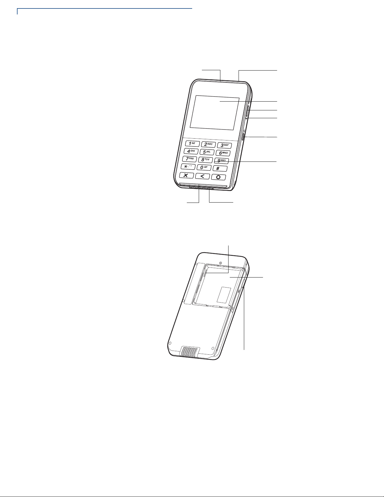
E355 DEVICE
LCD DISPLAY
KEYPAD
2D IMAGER
BARCODE BUTTON
POWER LED INDICATOR
SIDE MICRO-USB PORT
FRAME CONNECTOR
MAGNETIC STRIPE READER
SMART CARD READER
MSAM COMPARTMENT
BATTERY
COMPARTMENT
BARCODE BUTTON
Device Features
Below are the terminal features on the front panel.
Figure 1 Front Panel Features
Figure 2 shows the terminal features on the back panel.
Figure 2 Back Panel Features
12 E355/E265 USER AND BEST PRACTICES GUIDE
Page 13

E355 DEVICE
Software Features
Software
Features
Low Power Modes
Loadable drivers
e355 supports the following software features:
“Always On/Instant Activate” design similar to e315. Remote wake on data, no
data loss. All communication modes (USB, BT and Wi-Fi) support low power
modes. Sleep walking API (dark wake) feature from VX 690 device is supported.
Most e355 drivers are downloadable. This gives the advantage of updating the
driver without updating the OS. The following drivers are downloadable:
• Bluetooth
• Wi-Fi
• Barcode
• USB device
• USB host
• iAP1
• iAP2
• PMR-MUX2
Mobile PINpad
Architecture
Modular frame
iOS, Android/
Windows Protocols
• Frame Manager
• Ethernet-USB
• Battery monitor, and
• Contactless
e355 has the same Mobile PINpad architecture as the e315 device, providing
support of same virtual communication ports COM1A, COM1B, COM1C, COM1D
and COM1E over the protocols iAP1/iAP2 or PMR-MUX2 used to communicate
with smart device.
e355 can dock into different frames for connecting with iOS, Android, and
Windows smart devices. Frame detection and configuration happen early on
during e355 power-up. This means that users will need to restart e355 when they
switch to a different frame configuration. The default frame configuration is
Bluetooth, this is when there is no frame detected or error in frame detection
occurs.
e355 supports iAP1 protocol for iOS devices having 30 pin connector, iAP2
protocol for iOS devices having lightning connector and PMR-MUX2 protocol for
all Android and Windows devices. Wired connection (USB interface) uses any of
the three protocols iAP1, iAP2 and PMR-MUX2, whereas wireless (BT) interface
does not support iAP1, but supports iAP2 and PMR-MUX2 protocols.
E355/E265 USER AND BEST PRACTICES GUIDE 13
Page 14

E355 DEVICE
Software Features
Bluetooth Support
Wi-Fi Support
VTM on the Display
Software Changes
for PCI4
e355 shares the same hardware family as VX 690 device. The BT solution also
uses StoneStreetOne (SS1) BT stack. New SPP Server mode is supported, which
allows e355 to be discoverable in this configuration. Pairing modes are compliant
with PCI4 standard and supported profiles are SPP, OBEX and PAN.
e355 shares the same hardware family as VX 690 device and the same software
stack used by VHQ for device management. Mobile PINpad architecture is not
supported over Wi-Fi.
The e355 VTM is displayed on an LCD display unlike the e315's VTM, which is
displayed on a remote PC terminal such as Hyper Terminal. VTM menu layout is
similar as e315 and other Verix terminals. New menus such as sof tware ve rsions,
barcode diagnostic, contactless diagnostic, and IPP and ADE keys KSI
information are added.
The following software changes comply with PCI4 security standard:
• Added 24-hour restart change for memory initialization and file system
integrity check.
• Pre-expired passwords for key loading menus in VTM for RKL, ADE and IPP
keys.
Charging Schemes
Software Packaging
• Full system integrity check (file system integrity and binary files authentication)
at every boot-up.
• OS software hardening with buffer clearin g in secure modules af ter usage and
static code analysis fixes.
• Restrictions to BT pairing modes, only SSP numeric comparison is allowed.
Hardware supports simultaneous charging of e355 and smart device from frame
connector only (i.e., barrel and gang charger). However , simult aneous charging is
not supported from the side Micro-USB port of e355. Power sharing is also not
supported. Sequential charging is only supported in iPod 6 frame configuration
through the side Micro-USB port.
e355 uses Verix Package Installer (VPI) tool for packaging OS, drivers, EOS,
CTLS and applications. This allows for download of multiple components in single
download step with guaranteed order of install and to speed up package
installation process. NOVA package name is used for internal releases of e355
software, for example NOVA-01.00.03. Customer pa ckages are released on top
of the base NOVA packages with desired configuration parameters and software
components. For example,
for Verizo n custom er.
ZNOVA-01.01.02
is created on top of
NOVA-01.00.03
14 E355/E265 USER AND BEST PRACTICES GUIDE
Page 15
Architecture
NOTE
CHAPTER 2
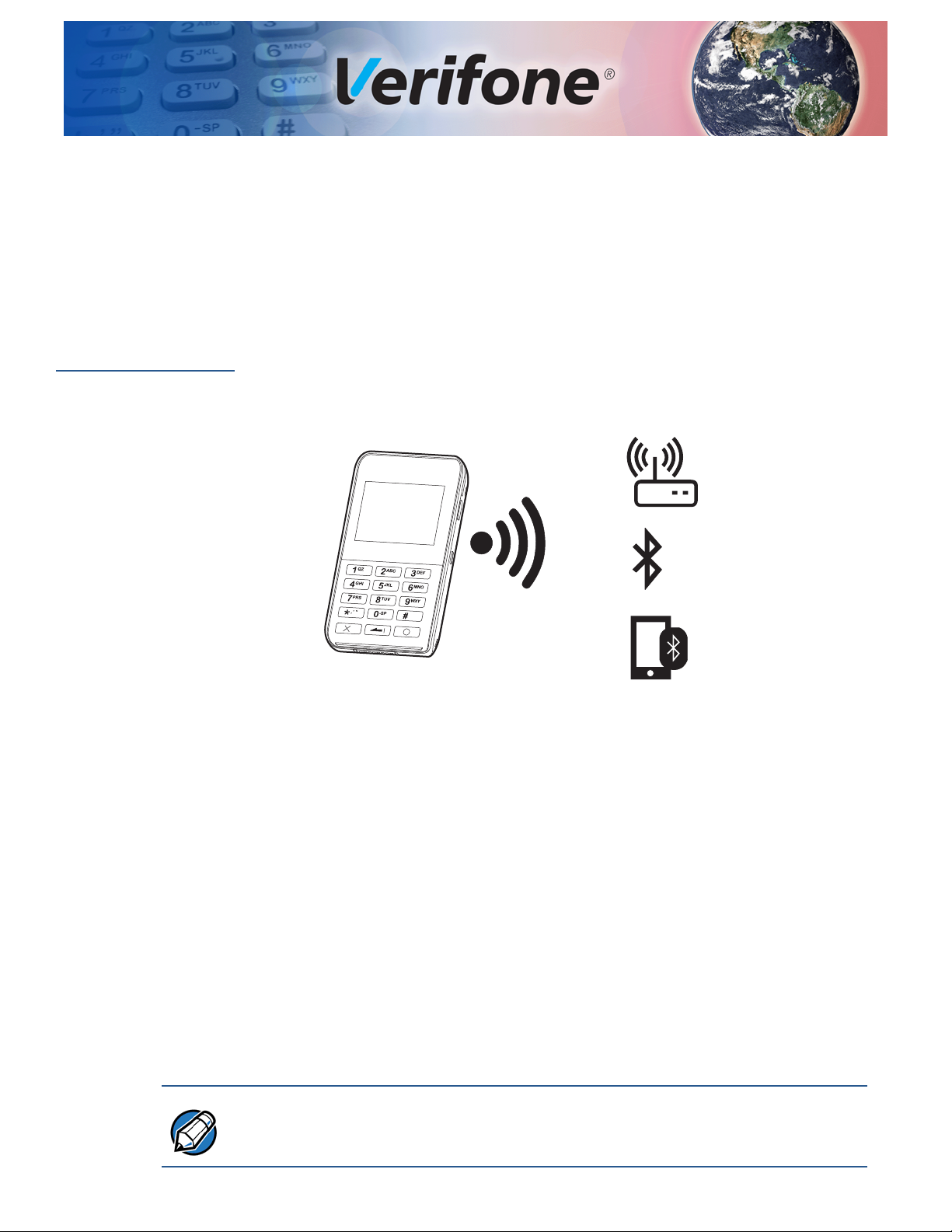
The e355 operates in Standalone and Mobile PINpad modes.
Standalone
Architecture
In this mode, e355 is not attached to a smart device and not docked in modular
frame. The payment application that processes the p ayment runs on the e355 and
the payment transactions are displayed on its LCD d isplay. Communications from
e355 to payment gateway is via Wi-Fi or Bluetooth interface only.
Figure 3 Communication via Wi-Fi Access Point, Bluetooth Access
Point, or Tethered Host via BT PAN Profile
Key Points in this set-up:
1 *GO configuration variable is set to payment application.
2 Disables the start-up of Control, Barcode, and Bluetooth Manager
applications.
3 Virtual Communication ports COM1A to COM1E are disabled.
4 Protocols iAP1, iAP2 and PMR-MUX2 for communicating with smart device
are disabled.
5 OS drivers, EOS, COMM engine (CE), and libraries are all available for use.
6 Possible to access control and barcode applications from payment
applications using pipe interface.
Smart Device P AN mode (tethering) is usually only supported on th e devices that
have a 3G/4G radio installed.
E355/E265 USER AND BEST PRACTICES GUIDE 15
Page 16
ARCHITECTURE
1
QZ.
#
X
2
ABC
3
DEF
4
GHI
5
JKL
6
MNO
7
PRS
8
TUV
9
WXY
*
,
‘
‘
‘
0
-SP
e355 Side
iPad mini Side
1
QZ.
#
X
2
ABC
3
DEF
4
GHI
5
JKL
6
MNO
7
PRS
8
TUV
9
WXY
*
,
‘
‘
‘
0
-SP
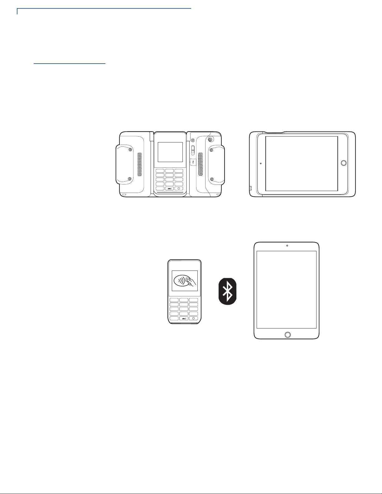
Mobile PINpad Architecture
Mobile PINpad
Architecture
In this mode, e355 is attached to a smart device and connected via USB or
Bluetooth interface. Payment application runs on the smart device and it drives
the e355 to perform actions of reading card data, taking PIN number, and
displaying messages on the LCD screen. The e355 provides five virtual
communication ports to the applications, which are multiplexed over USB or
Bluetooth interface. The iAP1/iAP2 and PMR-MUX2 protocols have the ability to
provide multiple virtual ports over single interface.
Figure 4 e355 To iPad mini via USB Interface
Figure 5 shows connection via BT.
Figure 5 e355 to iPad mini Via Bluetooth Interface
16 E355/E265 USER AND BEST PRACTICES GUIDE
Page 17
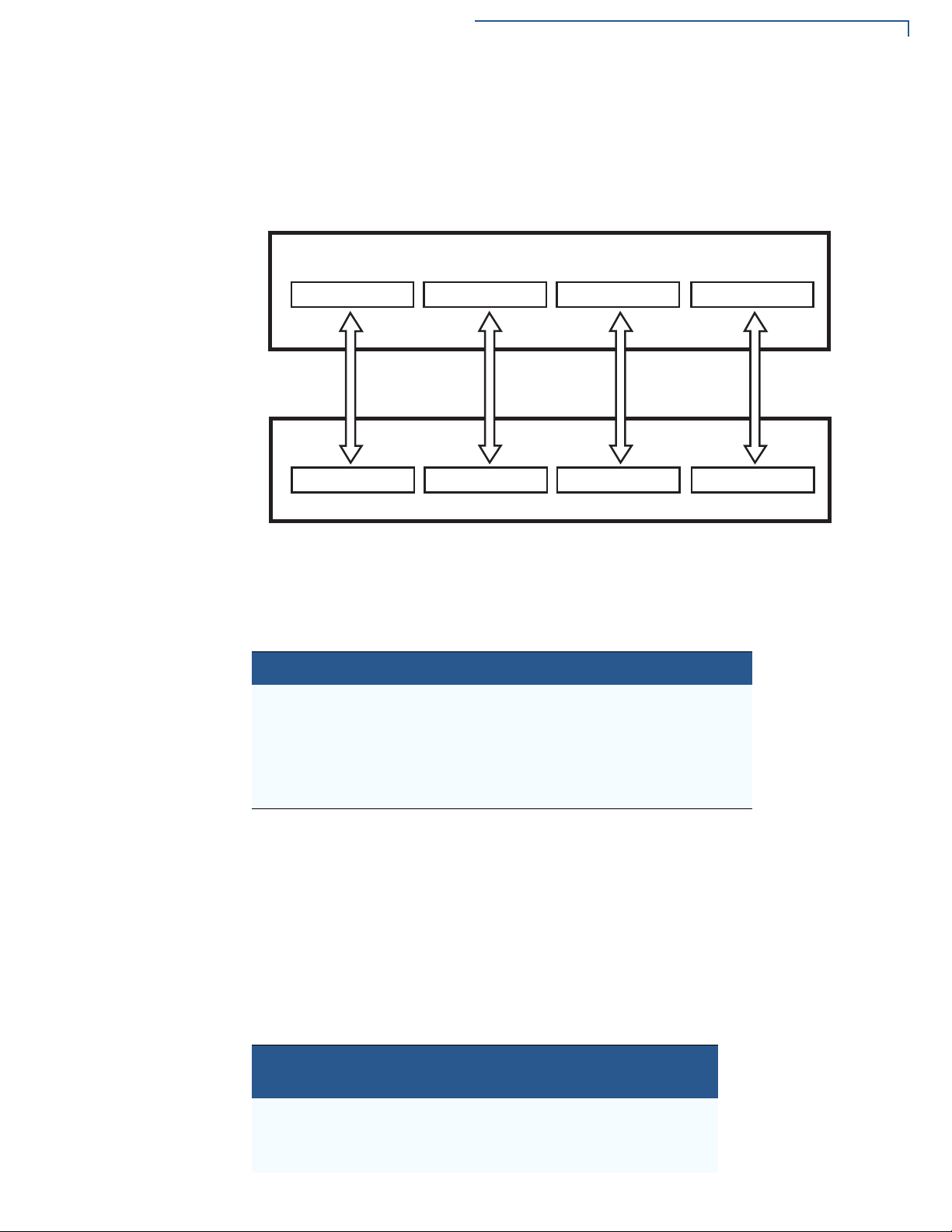
ARCHITECTURE
Protocol string1
Smart Device
Protocol string2 ... Protocol string5
COM1A
e355
...
COM1B COM1E
Mobile PINpad Architecture
Virtual
Communication
Ports
By virtue of iAP1/iAP2/PMR-MUX2 protocols, the smart device and e355 can use
separate communications ports. The smart device uses a unique protocol string
for starting the communications with corresponding virtual communication port on
e355 side.
Figure 6 Virtual Communication Port Architecture
Protocol Strings
Table 5 presents the protocol strings for iOS devices with Lightning and 30-pin
connectors, and the associated virtual COM ports.
Table 5 iOS Protocol Strings
Protocol Strings on iOS Virtual COM Ports on e355
com.verifone.pmr.xpi COM1A
com.verifone.pmr.barcode COM1B
com.verifone.pmr.zontalk COM1C
com.verifone.pmr.control COM1D
com.verifone.pmr.debug COM1E
Apple iOS device with Lightning connector uses iAP2 protocol to communicate
with e355, and Apple iOS device with 30-pin connector uses iAP1 protocol to
communicate with e355. Both iAP1 and iAP2 protocols use the same protocol
strings on iOS device. For more information on communicating with accessory
using protocol strings, refer to External Accessory Framework on the Apple
developer website.
Table 6 shows protocol strings (commands) for Android/Windows devices and the
associated virtual COM ports.
Table 6 Android/Windows Protocol Strings
Protocol Strings on
Android/Windows
<0xFF5A><o2><CRC> COM1A
<0xFF5A><o3><CRC> COM1B
<0xFF5A><o4><CRC> COM1C
Virtual COM Ports on e355
E355/E265 USER AND BEST PRACTICES GUIDE 17
Page 18

ARCHITECTURE
Mobile PINpad Architecture
Table 6 Android/Windows Protocol Strings (continued)
Device Ports
Protocol Strings on
Android/Windows
<0xFF5A><o5><CRC> COM1D
<0xFF5A><o6><CRC> COM1E
Virtual COM Ports on e355
PMR-MUX2 protocol uses commands to open, send, and close the
communications ports. For full details on the PMR-MUX2 protocol, refer to section
PMR-MUX2.
Applications running on e355 open the virtual COM device ports COM1A,
COM1B, COM1C, COM1D, and COM1E. These applications respond to the data
sent to these ports.
Table 7 shows the application names that open specific device ports.
Table 7 Applications vs. Device Ports
Virtual COM Port on e355 Application Owner
COM1A mADK/XPI application
COM1B Barcode application
COM1C Zontalk downloads
COM1D Control application
COM1E Debug message output
XPI application uses COM1C port for supporting Zontalk downloads in addition to
its COM1A port for communicating with smart devices. The last COM1E port is
available for debug message output. There are no applications using this port.
Open and Close Events of Communication Ports
The e355 sends a Connect event to its application when application on the smart
device opens the port for communication. The e355 sends a Disconnect event
to its application when application on smart device closes the communication port.
If the e355 application has not opened the device port, but application on smart
device tries to open it, then e355 responds with an error code.
Applications on e355 can use API get_port_status() for detecting open and
close status of communication port in the smart device application.
Device Port APIs
Following are the APIs used by the device ports.
18 E355/E265 USER AND BEST PRACTICES GUIDE
Page 19

open()
ARCHITECTURE
open()
This claims ownership of the device. Calling this function also flushes all data an d
clears all error conditions in the communication channel. The device names that
can be opened for ports are:
"/DEV/COM1A"
"/DEV/COM1B"
"/DEV/COM1C"
"/DEV/COM1D"
"/DEV/COM1E"
Use get_port_status() to get the status of the smart device connection. A
smart device cannot open a communication port until the e355 application has
opened the corresponding device.
close()
Prototype Int open(const char *devname, int attributes);
Parameters
devname Pointer to the null terminated device name string.
attributes Ignored in this driver.
Return Values Positive integer device handle if successful, or -1 with errno set to an error code
if error occurs.
This releases ownership of the device. Calling this function also flushes all data
and clears all error conditions in the communication port.
Prototype int close(int device_handle) parameters:
Parameters
device_handle The handle returned for the device by the open() call.
Return Values Returns 0 for success, -1 with errno set to EBADF if device not open.
E355/E265 USER AND BEST PRACTICES GUIDE 19
Page 20

ARCHITECTURE
rea d()
read()
This copies message-based data (header, data, CRC) received from the
communication port to the given buffer . The actual number of bytes copied may be
less than the requested count. In e355, the receive data logic drop s packet s larger
than 1024 bytes for iOS devices and 2048 bytes for Android and Windows
devices.
The Rx message packets are first put into a FIFO of up to 7 message packet s and
a kernel task routes the message packets to the correct device port buffers. It is
possible, but unlikely that the kernel task can't keep up with the incoming packet s.
If the FIFO overflows, the entire message packet is dropped. When packets are
internally dropped, log messages are generated. The end-to-end request/
response handshaking normally prevents buffer overflows.
The read function returns a complete message that is aligned on packet
boundaries. The communication port driver does a CRC checksum on the data to
assure integrity, but, it does not guarantee delivery.
Prototype int read(int handle, char *buffer, int count);
Parameters
handle The handle returned for the device by the open() call.
buffer The buffer from which to copy the data.
count The maximum number of bytes requested.
Return Values Returns the number of bytes read, or -1 if an error occurred.
20 E355/E265 USER AND BEST PRACTICES GUIDE
Page 21

write()
ARCHITECTURE
write()
This copies the given data to system transmit buffers for transmission over the
communication port. The function may return before the data is actually sent. In
e355, the write() function works differently than a standard serial port. The
driver assumes that each write contains a whole packet and that a request/reply
type of protocol is running on the link that limits the number of outstanding
transmit packets in the buffers. Usually, a device port will have, at most, one
outstanding packet in the buffers. No packet is sent until a response is received.
There are a total of 7 transmit buffers shared among all channels. If a
communication protocol attempts to write when there are no buffers, the error
ENOSPC is returned. Each buffer allows up to 1024 bytes for iOS devices and
2048 bytes for Android and Windows devices.
Prototype int write(int handle, const char *buffer, int count);
Parameters
Return Values Returns the number of bytes sent, or -1 if an error occurred.
Reset_port_error()
Prototype int reset_port_error(int handle);
Parameters
Return Values Returns 0 if successful, or -1 if an error occurred.
handle The handle returned for the device by the open() call.
buffer The buffer from which to copy the data.
count The number of bytes to send.
Resets all error flags for the given communication channel.
handle The handle returned for the device by the open() call.
E355/E265 USER AND BEST PRACTICES GUIDE 21
Page 22

ARCHITECTURE
Get_port_status()
Get_port_status()
Parameters
Return Values Returns 0 if no output is pending, 1 if output is pending, or -1 if an error occurred
handle The handle returned for the device by the open() call.
buffer The 4-byte buffer in which to copy the status information.
and errno is set to an error code.
For a communication port, the four status bytes copied into the given buffer are as
follows:
• Byte 1: The number of input messages pending.
• Byte 2: Event Cause Bits described below.
• Byte 3: The number of output messages pending.
• Byte 4: The status byte described below.
The event cause bits are set when an event is sent to the application. The
application can read the bits to determine the cause of the event. The event cause
bits are cleared when they are read. The definitions are as follows:
Table 8 Event Cause Bits
Bit Event Definition
Bit 0 Connect Event Set when a communication port is opened.
Bit 1 Disconnect Event Set when a communication port is closed or Bluetooth
connection is lost.
Bit 2 RX Ready Set when new received data is ready to be read.
22 E355/E265 USER AND BEST PRACTICES GUIDE
Page 23

set_event_bit()
Prototype int set_event_bit(int handle, long bitmask);
Parameters
ARCHITECTURE
set_event_bit()
Allows the application to select one of the event bits that would otherwise be
unused, and assigns it to a communication port.
By default, the communication ports do not generate events. This function allows
the communication ports to generate events when data is received. This
mechanism is provided when almost all the bits in the event mask have already
been allocated. However , in a specific terminal installation, many of the predefined
event bits are not used.
handle The handle returned for the device by the open() call.
bitmask A mask with 1 or 0 bits set corresponding to the event bit.
Return Values Returns 0 if successful. If an error occurs this function returns -1.
get_event_bit()
Prototype long get_event_bit(int handle);
Parameters
Only one event bit may be selected for a given device. The following event bits
must not be assigned: EVT_USER, EVT_SHUTDOWN and EVT_SYSTEM.
Any attempt to violate these rules will result in set_event_bit() returning -1
and errno being set to EINVAL. If the command fails, the event bit setting will not
be changed.
Allows the application to find out what event, if any, will be generated by the given
device. The mask returned will have one bit set that corresponds to the event bit
generated by the device.
handle The handle returned for the device by the open() call.
bitmask A mask with 1 or 0 bits set corresponding to the event bit.
Return Values Returns 0 if no event is to be generated or a mask with one bit se t, if an event is to
be generated. -1 if the device does not support soft events.
E355/E265 USER AND BEST PRACTICES GUIDE 23
Page 24

ARCHITECTURE
iap_control_function()
iap_control_function()
Prototype int iap_control_function (int handle, int function);
Parameters
This allows an application to control the keypad state. The possible functions
defined in SDK header, SVC.H, are:
• IAP_CONTROL_KEYPAD_SLEEP, turns off the keypad.
• IAP_CONTROL_KEYPAD_WAKE, turns the keypad on.
• IAP_CONTROL_DISABLE_KEYBEEP, turns off the keypad beeps.
• IAP_CONTROL_ENABLE_KEYBEEP, turns on the keypad beeps.
handle The handle returned for the device by the open() call.
function An integer specifying the function to be performed.
Return Values Returns 0 if successful. If an error occurs, the function returns -1 and errno is se t
to an error code.
iap_get_keypad_state()
Copies the keypad status to the given buffer. The first byte is the "Enable State."
The second byte is the "Beep State." The two status bytes are as follows:
• <Enable State>
0 if keypad is disabled, 1 if keypad is enabled and awake, 2 if keypad is
enabled, but still waking up.
• <Beep State>
0 if beeps are disabled, 1 if beeps are enabled.
Prototype int iap_get_keypad_state (int handle, char*buffer);
Parameters
handle The handle returned for the device by the open() call.
buffer A buffer of at least 2 bytes to hold keypad status.
Return Values Returns 0 if successful. If an error occurs, the function returns -1 and errno is se t
to an error code.
24 E355/E265 USER AND BEST PRACTICES GUIDE
Page 25

ARCHITECTURE
iap_get_keypad_state()
Communication
Protocols
Below are the communication protocols:
iAP1
The iAP1 protocol is an Apple accessory protocol specified in MFi Accessory
Firmware Specification R46 for Apple 30-pin connector devices. This requires
Apple authentication coprocessor to validate e355 as valid Apple accessory
before being able to communicate with iOS device. Frame ID reading selects the
iAP1 protocol early on during the e355 power-up or restart. iAP1 is only supported
on USB interface and not supported on Bluetooth interface. Maximum message
size for read and write operations is 1024 bytes (1012 bytes payload), which is
same as iAP2 maximum message size.
iAP2
The iAP2 protocol is a complete replacement of iAP1 protocol and is not backward
compatible with iAP1. The iAP2 protocol is used specifically with the newer 8-pin
Lightning connector for iOS devices. The iAP2 protocol is specified in MFi
Accessory Interface Specification, which requires Apple authentication
coprocessor to validate e355 as valid Apple accessory before being able to
communicate with iOS device. The frame ID value selects the iAP2 protocol early
on during the e355 power-up initialization. The iAP2 protocol is also supported on
USB and Bluetooth interfaces. Maximum message size for read and write
operations is 1024 bytes (1012 bytes payload).
Application Auto-Launch
This feature is supported in iAP2 driver version V01.05.04 and later.
*APP_LAUNCH_ID is used to specify a unique Application Bundle ID.
Example: *APP_LAUNCH_ID=com.verifone.e355
Configuration variable *IOS_APP_ALERT is used to alert the user before
launching the application specified by *APP_LAUNCHID when an iAP2
accessory is connected. User alerts can be disabled for USB connection but
not for Bluetooth.
• *IOS_APP_ALERT=1 will launch the application with no user alert.
• *IOS_APP_ALERT=0 will launch the application with user alert.
PMR-MUX2
Verifone developed a custom PMR-MUX2 protocol. Following are the key points
about this protocol:
• Used over Bluetooth SPP and USB interfaces.
• Protocol is message based and not stream based, increases the
communications integrity.
• Message header contains virtual com channel number.
E355/E265 USER AND BEST PRACTICES GUIDE 25
Page 26

ARCHITECTURE
iap_get_keypad_state()
• Message-based protocol allows for CRC verification of each message.
• Maximum message size is 2048 bytes (2040 bytes for payload).
• Applications can write any size data, but must verify the number of bytes
written and repeat write until total number of bytes written.
Table 9 presents the PMR-MUX2 protocol commands.
Table 9 PMR-MUX2 Protocol Commands
Command String
<0xFF 0x5A>o<num><crc> Open Channel This command opens th e channel number specifie d by the
<0xFF 0x5A>c<num><crc> Close Channel This command is sent by the smart device to close a given
Command:
<0xFF><0x5A>i<crc>
Response:
<0xFF><0x5A>i<Length><crc>
<0xFF><0x5A>d<num>
<length><data><crc>
Command
Name
MTU Query Query for Maximum Transmission Unit (MTU) which is
Channel data
message
Description
<num> parameter. The command character is a 1 byte
lower case letter ‘o’. The <num> parameter is a one byte
ASCII number from 2 to 6 to specify which channel to
open. This is sent when the smart device opens a channel.
The <crc> field is a 16 bit CRC of the complete message
including the 2 byte header and the command me ssa ge
data.
channel. The command character is a 1 byte lower case
letter ‘c’. The <num> parameter is a 1 byte ASCII number
from 2 to 6 to specify the channel number . The <crc> field
is a 16 bit CRC of the complete message including the 2
byte header and the command message data.
used to indicate the maximum message frame length for
mux protocol. The command character is a 1 byte lower
case letter ‘i’. This should be used by all smart devices
using this protocol in case of buffer length changes in the
future. This returned length includes both the message
header, body and CRC. The length is 4 byte ASCII Hex.
The <crc> field is a 16 bit CRC of the complete message
including the 2 byte header and the command me ssa ge
data.
This command sends/receives a data message to/from a
selected channel. The command character is a 1 byte
lower case letter ‘d’. The <num> paramete r is 1 byte ASCII
number from 2 to 6 to specify the channel number.
Channel number of XPI is 2, barcode 3, Zontalk 4, control
5, and debug 6. The <length> is a 4 byte ASCI Hex
string from 0000-MTU length in “I” command. The <crc>
field is a 16 bit CRC of the complete message including
the 2 byte header and the data field.
26 E355/E265 USER AND BEST PRACTICES GUIDE
Page 27

ARCHITECTURE
iap_get_keypad_state()
Table 10 presents the PMR-MUX2 status strings.
Table 10 PMR-MUX2 Status Strings
Message Status String Name Description
<0xFF><0x5A>a<num><crc> ACK Indication This Message Status is a method for either end of the
link to send and ACK status to the other end. This
indicates that the previous message was received
properly. The <num> parameter is an ASCII number
from 2 to 6 to specify the channel number. The <crc>
field is a 16 bit CRC of the complete message including
the 2 byte header and the data field.
<0xFF><0x5A>n<num><code><crc> NAK indication This Message Status is a method for either end of the
link to send NAK error codes to the other end in the
event of a message error. The error codes are a single
byte ASCII values. The specific error codes are
described below. The <num> parameter is an ASCII
number from 2 to 6 to specify the channel number. The
<crc> field is a 16 bit CRC of the complete message
including the 2 byte header and the data field.
Table 11 lists the PMR-MUX2 error codes.
Table 11 PMR-MUX2 Error Codes
Error
Code
0x31 Channel not open The OS sends this error when the smart device application attempts to write
0x32 Invalid Channel Number The OS sends this error when the smart device app specifies a bad channel
0x33 No Channel is selected The OS sends this e rror when a command doesn't cont ain a channe l number.
0x34 Unknown Command The OS sends this error when a command byte is received that it does not
0x35 Channel Already Open The OS sends this error when the smart device application tries to open a
0x36 Channel Already Closed The OS sends this error when the smart device application tries to close a
0x37 Application Not Open The OS sends this error when the smart device application tries to open or
Code Name Description
to a mux channel that it has not opened.
number in an open or close command.
recognize.
channel that is already open.
channel that is already closed.
write to a channel in which the Verix application has not opened the channel.
E355/E265 USER AND BEST PRACTICES GUIDE 27
Page 28

ARCHITECTURE
iap_get_keypad_state()
Example CRC Algorithm used in PMR-MUX2 protocol:
Software
Components
Software components are described below.
Operating System
Verix Operating Syst em consists of low-le vel device drivers and high-level system
services, compliant with PCI4 security standard. OS release versions include
build date, for example: QTE50301-20151006 or WTE50301-20151006. For more
information on the V erix Operating System, refer to V erix eV o V o lume I: Operating
System Programmers Manual - VPN DOC00301.
Downloadable drivers
Most OS drivers of e355 are downloadable. Following is the list of downloadable
drivers:
• Bluetooth
• Wi-Fi
• USB Device
• USB APL(Host)
• iAP2 Channel
• Frame Manager
• Barcode
• Ethernet-USB
• iAP1
• CTLSL1, and
• Battery Monitor
28 E355/E265 USER AND BEST PRACTICES GUIDE
Page 29

ARCHITECTURE
iap_get_keypad_state()
Extended Operating System (EOS)
Supports TCP/IP stack, Wi-Fi, and Bluetooth connection management, and
Network control Panel (NCP). For more information on Extended Operating
System, refer to Verix eVo Volume II: Operating System and Communication
Programmers Guide, VPN - DOC00302.
Channel Application
The channel application is a system application used for OS services. It is signed
with OS certificates and runs from N drive and group 46, in EOS space. This
application communicates with Bluetooth Manager application via pipes for SPP
link up or down status and opens USB or Bluetooth interface based on the frame
ID value and selects the appropriate iAP1/iAP2/PMR-MUX2 protocol. This
application services are used only in Mobile PINpad mode, and not required in
standalone mode. The version information of this application is displayed in VTM
software versions menu.
*GO application
In Mobile PINpad mode, Control application is *GO application and remain ing user
applications are launched by the control application using the configuration
variable *VXAPPx.
In Standalone mode, Payment application is the *GO application.
*VXAPPx
In Mobile PINpad mode, the user applications other than control application, are
specified as configuration variables *VXAPPx, where X is the numeric digit (1
through 9) and the order number of launch. The numbers specified by X must be
contiguous.
Example In ZNOVA software package the remaining user applications are launched in the
following order: *VXAPP1 = BT_MGR.OUT, *VXAPP2 = BARCODEAPP.OUT
and *VXAPP3 = IMM.OUT (XPI)
BT_MGR application
This application is launched by control application when frame ID value is equal to
Bluetooth only. This application provides the user interface for Bluetooth device
configuration, pairing and discoverability, and Serial Port Profile (SPP)
configuration and link management.
e355 Data Flow
Figure 7 shows the software components and software layers, and how the
software components communicate with each other.
• The OS frame manager driver reads the frame ID value during power-up and
saves that value for the applications to read. Channel application retrieves the
frame ID value to select the right interface among Bluetooth, USB host, and
USB device interfaces.
E355/E265 USER AND BEST PRACTICES GUIDE 29
Page 30

ARCHITECTURE
iap_get_keypad_state()
• Channel Application uses the frame ID value to select the appropriate
interface (USB/lightning/Bluetooth) and message protocol (iAP1/iAP2/PMRMUX2).
• Channel Application communicates with BT_MGR application via pipe
interface for Bluetooth profile connection management.
• User Applications like Control Application, Barcode, and mADK/XPI can
access virtual COM Ports (COM1A...COM1E) via iAP1/iAP2/PMR-MUX2
protocols.
Figure 7 Data Flow Diagram
30 E355/E265 USER AND BEST PRACTICES GUIDE
Page 31

Communication Interfaces
Barcode Buttons
Frame Connector
Gang Charger Pins
Power Barrel Slot
Side Micro-USB Port
This chapter discusses communication interfaces via USB and Bluetooth.
CHAPTER 3
USB
USB Host
There are three supported USB interfaces.
The e355 USB host interface is used in Mobile PINpad operation mode for frame
ID values iPad mini, iPad mini 4, iPad 2, and iPod 6. The e355 USB host port
connects to iOS device through an 8-pin frame connector.
iPad mini Frame
Key Points:
• This frame is with 8-pin Lightning connector.
• e355 is an accessory to iPad mini device.
• As an accessory, e355 cannot wake-up iPad mini.
• iAP2 protocol is used over USB host interface.
• iAP2 charging command is sent from e355 to iPad mini to charge at 2.1 A
when external AC power is connected to frame.
• Barcode trigger buttons are available on iPad mini frame.
• Barcode trigger buttons on the frame can be used to enable pass-through
mode.
Figure 8 Frame for iPad mini
E355/E265 USER AND BEST PRACTICES GUIDE 31
Page 32

COMMUNICATION INTERFACES
Micro-USB Port
Frame Connector
USB
iPad 2 Frame
Key Points:
• This frame is with 30-pin iPad 2 connector.
• e355 is an accessory to iPad 2 device.
• As an accessory, e355 cannot wake-up iPad 2.
• iAP1 protocol is used over USB host interface.
• iAP1 charging command is sent from e355 to iPad 2 to charge at 2.1 A when
external AC power is connected to frame.
• No barcode trigger buttons on iPad 2 frame.
Figure 9 Frame for iPad 2
iPod 6 Frame
Key Points:
• This frame is with an 8-pin Lightning connector.
• e355 is an accessory to iPod 6 device.
• As an accessory, e355 cannot wake-up iPod 6.
• iAP2 protocol is used over USB host interface.
• iAP2 charging command is sent from e355 to iPod 6 to charge at 1 A when
external AC power is connected to frame.
• Barcode trigger buttons are available on iPod 6 frame.
• Barcode trigger buttons on the frame can be used to enable pass-through
mode.
32 E355/E265 USER AND BEST PRACTICES GUIDE
Page 33

COMMUNICATION INTERFACES
Barcode Button
Lightning Connector
8-Pin Interface To Smart Charger
USB Port for
Simultaneous Charge
Side Micro USB Port
• Micro-USB port on the bottom of this frame is for simultaneous charge.
Figure 10 Frame for iPod 6
USB
USB Device
The USB device interface is used in Mobile PINpad mode for frame ID values
Android and Windows. The USB device port connects to Android/Windows device
through an 8-pin frame connector. The side Micro-USB is not accessible for USB
downloads when e355 is in Android/Windows frame configuration.
Android Frame
Key Points:
• This frame is with Micro-USB type B connector.
• e355 is an accessory to Android device.
• As an accessory, e355 cannot wake-up Android device.
• PMR-MUX2 protocol is used over USB device interface.
• Android charging is set by HW resistor ID to charge at 1.8 A when external AC
power is connected to frame.
• Barcode trigger buttons are available on Android frame.
E355/E265 USER AND BEST PRACTICES GUIDE 33
Page 34

COMMUNICATION INTERFACES
Side Micro-USB Connector
Barcode Buttons
Frame Connector
Gang Charger Pins
Power Barrel Connector
USB
• Communication link will be broken between e355 and Android device when
external AC power is connected to frame, link will be re-established after
external AC power disconnection.
Figure 11 Frame for Android
Windows Frame (HP Tablet)
Key Points:
• e355 is an accessory to Windows device.
• As an accessory, e355 cannot wake-up Windows device.
• PMR-MUX2 protocol is used over USB device interface.
• Windows charging is set by Power Delivery (PD) controller to charge at 1.5A
when external AC power is connected to frame.
• Barcode trigger buttons are available on Windows frame.
• Communication link is broken between e355 and Windows device when
external AC power is connected to frame.
Side Micro-USB port
Key Points:
• For charging e355 only.
• Software package downloads over USB from PC.
• Service board connection for downloads over serial port and logging
• Pass-through connection to tablet (data sync).
• Virtual communications ports (COM1A,..COM1E) are not supported over this
port.
• Control commands are supported and accessed via side Micro-USB port in
iOS frame configurations. Command format is defined in control application
document.
34 E355/E265 USER AND BEST PRACTICES GUIDE
Page 35

COMMUNICATION INTERFACES
NOTE
Bluetooth
Bluetooth
The e355 Bluetooth device is BCM 43340 BT/Wi-Fi integrated chip that supports
BT 2.1+ EDR. The Bluetooth interface is enabled whenever the e355 is turned on
and not installed in a frame.
If the device is installed in a frame and then removed the e355 must be rest arted
to go into Bluetooth communications mode.
The Bluetooth device provides low power consumption and operation and is
capable of staying paired and connected while in deep sleep mode and waking up
to receive data. If the Bluetooth device is connected to/from a smart device with
either SPP/PAN profiles, it will maintain the connection and not automatically
power down.
The Bluetooth Manager (BT_MGR) application provides the user interface for
pairing to/from a smart device, connecting to/from SPP/PAN profile on the smart
device and Bluetooth link management. Being paired with a device does not mean
that the e355 and smart device are connected. To be connected, the e355 must
be linked to one of the supported profiles.
The Bluetooth Managers document has all the details need for pairing and
connecting to profile services to/from a smart device. For more information, refer
to Verix eVo Bluetooth Manager Users Guide, VPN - DOC00327.
Supported Profiles
The following profiles are supported:
Serial Port Profile (SPP)
The e355 supports SPP for both Client/Server modes. The BT_MGR application is
used to configure these profile. By default, SPP port is used for SPP Client mode
and SPP2 port is used for SPP Server mode. These ports can be used
simultaneously.
When in SPP Client Serial Mode, BT_MGR provides Bluetooth link maintenance
and reconnection logic. When in SPP Server mode, the smart device is in SPP
Client mode and must perform Bluetooth link maintenance and reconnection logic.
Apple
The e355 can connect to iOS device via iAP1/iAP2 protocol over SPP in both
Client and Server modes. The iAP1/iAP2 service is always running on the iOS
device so connecting to the device in Client mode is much easier.
Android/Windows
The e355/e265 connects to an Android/Windows device via custom PMR-MUX2
protocol over SPP in both Client and Server modes. When connecting e355 to
Android/Windows device in SPP Client mode, the SPP Server must be running on
the smart device. If the SPP service is not running on the smart device, it will pair
but not connect.
E355/E265 USER AND BEST PRACTICES GUIDE 35
Page 36

COMMUNICATION INTERFACES
NOTE
Wi-Fi
Personal Area
Network (PAN)
Profile
The BT_MGR application is used to configure this profile. This profile is used to
connect to a smart device in tethered mode to access the internet. When
connected in PAN Mode, BT_MGR provides Bluetooth link maintenance and
reconnection logic.
By default PAN profile is not available from the BT_MGR user interface. This
feature can be enabled via a configuration variable. For more information, refer to
Verix eVo Bluetooth Manager Users Guide, VPN - DOC00327.
Smart Device PAN mode (tethering) is usually only supported on smart devices
that have a 3G/4G radio installed.
Bluetooth Manager (BT_MGR) Role and OS Interaction
This is documented in detail in Verix eVo Bluetooth Manager Users Guide, VPN DOC00327 for more information.
Bluetooth Pairing
This is documented in detail in Verix eVo Bluetooth Manager Users Guide, VPN DOC00327 for more information.
Wi-Fi
Pairing Behavior
Apple iOS devices don't always pop up the numeric comparison window for
pairing if the device was previously connected even after you "Forget Device." If
you "Forget Device," turn off Bluetooth, reset device, turn on Blue tooth, it will then,
most-of-the-time, pop up numeric comparison window. If you don't mind that you
can just press OK on the connecting device and it will still pair. Recent iOS
updates have improved this behavior.
Wi-Fi interface is available on e355 device. Mobile PINpad architecture is not
available over Wi-Fi interface. This interface is primarily used for VHQ
communications. In the standalone mode it can be used as a general purpose
communication interface.
Per PCI4 requirements, open and WEP encryption modes are not permitted. The
available encryption modes are:
• WPA2-Personal
• WPA(2)-Enterprise (EAP-TLS, EAP-FAST, EAP-PEAP)
The device supports both 2.4GHz and 5 GHz bands. It can be set to use only one
of these bands or both the bands ("auto") from NCP. This setting is available
under Wi-Fi device driver setup.
Low power Wi-Fi modes are supported in e355. This mode is configurable from
NCP. Power Mode 2 is default and recommended. An application usually does not
directly work with the Wi-Fi driver. It is used by the Communication Engine library
packaged with EOS.
36 E355/E265 USER AND BEST PRACTICES GUIDE
Page 37

Power
NOTE
CHAPTER 4
This chapter discusses the different ways of powering up and conserving power
on e355.
Charging
Side Micro-USB Port
Only
Simultaneous
Sequential (Only on
iPod 6 Frame)
The e355 supports multiple charging schemes as follows:
This charging method charges e355 device only when power is attached to the
side Micro-USB port of e355. This is true even when connecting to this port while
attached to frame in Mobile PINpad mode with smart device attached to e355.
With the exception of iPod 6 frame, where sequential charging to e355 a nd iPod is
allowed through this port.
This charging method is specific to Mobile PINpad mode, and charges e355 and
smart device at the same time. Power supply needs to be connected to barrel
connector or charging pins or Micro-USB connector located on bottom of iPod 6
frame, whichever is available and your preference of power supply connection.
This charging method is also specific to Mobile PINpad mode and charges one
device at a time. For example, it will charge e355 first and then the smart device
second. A Micro-USB charging cable needs to be attached to side Micro-USB port
for sequential charging.
This charging scheme is only supported for iPod 6 frame.
To enable sequential charging, set configuration variable *CHARGEHOST to nonzero value, default value is 0 for this variable, with range of 0-100 (in battery
percentage level). The e355 charges to battery level specified by *CHARGEHOST
configuration variable before switching to iPod charging.
Another configuration variable that's used is *IPODCHARGETIME which is used to
specify iPod charge time. Default value is 90 minutes, and range of 0 to 12*60 (in
minutes). After expiration of iPod charge time, charge switches back to e355 and
remains with e355 until Micro-USB cable is disconnected. A value of 0 disables
charge switch back to e355 and continuously charges the iPod until Micro-USB
power is disconnected. Sequential charge sequence starts again every time
power is applied to side Micro-USB port i.e, e355 charges to *CHARGEHOST level
and then iPod charges for *IPODCHARGETIME.
E355/E265 USER AND BEST PRACTICES GUIDE 37
Page 38

POWER
WARNING
On and Off
Power Sharing
On and Off
Power On
This charging method is specific to Mobile PINpad mode and charges smart
device from e355 battery power. This charging method is deprecated in e355
hardware due to high charging current requirement for some smart devices.
Table 12 shows the charging current per charging method.
Table 12 Charging Current
Charging Method e355 Smart Device
Device only (e355 side Micro-USB) 700 mA n/a
Simultaneous 1 A 2.1 A
Sequential 1 A 1 A
Power Sharing n/a n/a
There is no dedicated On/Off switch for e355.
The e355 powers on for any of following events:
• Green key held down for 4+ seconds.
• Smart device attached to frame (accessory power pin).
• Power attached via Micro-USB power or barrel connector or gang charger.
Power Off
Hidden Reset
Button
The e355 powers off for any of following events:
• Red key held down for 4+ seconds, but blocked when smart device attached
via Lightning/USB.
• Critical low battery level is reached, battery voltage 3.35 v.
• SVC_SHUTDOWN() API is called from application or VTM menu to power
down, but blocked when smart device attached via Lightning/USB.
• Deep sleep timer (*OFF) expires, but blocked when smart device attached via
Lightning/USB or smart device connected to e355 via Bluetooth.
There is a pin-hole button to hard reset e355 device, located near barcode button
and battery status LED.
It is strongly advised NOT to use this pin for standard on/off procedure as it is
possible to damage the e355. Use ONLY as last resort when e355 is not
responding.
38 E355/E265 USER AND BEST PRACTICES GUIDE
Page 39

POWER
Power Modes
Power Modes
Off
Active
Power modes are independent in e355 and attached smart device. There are
three power states in e355—OFF, ACTIVE, and SLEEP.
Processor and its peripherals are powered off. When it is next powered on, the
unit goes though full boot-up cycle, SW stack initialization and applications
executing from "main" routine. Off state transition is blocked when e355 is
connected to smart device, either via USB or BT.
There are two active states for e355.
Active Run
The unit is in the Active Run state whenever an application is running. The
processor will run at full speed as long as any application is ready to run. The
"core" of the microprocessor is consuming full power. Even in this state, other
parts of the system may be shut down or at least consuming less than the
maximum amount of power.
Active Idle
The unit is in Active Idle state when applications are suspended (by calling
wait_event or SVC_WAIT), the processor is then slowed. This happens
immediately, and just as quickly, the system can transition back to Active Run
state when work arrives to wake up an application. It is not possible to distinguish
between Active Run and the early stage of Active Idle state. They appear the
same but the system clock is running at a lower clock speed, and other internal
mechanisms are shut down when not being used. The terminal consumes
considerably less power than when it is Active Run.
Sleep
The e355 goes into Active Idle state af ter all the applications are suspended for 20
seconds (default *POW configuration setting). Transition is automa tic to next sleep
state (snooze or deep sleep). E355 LCD display transitions to dim in the active
Idle state.
Two sleep states are supported by e355—snooze and deep sleep.
Snooze
Snooze state is applicable only when Lightning/USB interface is connected to
smart device. USB peripheral is always active and all other peripherals are
powered down in this state. USB data traffic instantly wakes e355 to full active
run, without loss of packets or data. e355 LCD display transitions to dark (Off) in
deep sleep state.
E355/E265 USER AND BEST PRACTICES GUIDE 39
Page 40

POWER
Power Modes
Deep Sleep
Deep sleep state is applicable only when USB interface is NOT connected to
smart device. This is the lowest possible power state with current consumption
around 12 mA, all peripherals are powered down and CPU clock runs at 32 kHz in
this state. BT/Wi-Fi data instantly wakes e355 from deep sleep without loss of
packets or data. e355 LCD display transitions to dark (appears Off) in deep sleep
state.
Power Environment
Variables
Power Best
Practices
• *PM configuration variable is a master environmental setting for conveniently
selecting a standard power management profile. Setting this variable to one of
three settings (0 = Max Performance, 1 = Max Operational or 2 = Max
Standby) will set a combination of variables at one time including the *POW
and *OFF variables below. This variable is not configured by default . For more
information, refer to Verix eVo Volume 1 Operating Systems Programmers
Manual, VPN - DOC00301.
• *POW configuration variable is for specifying applications idle time before
going to Active Idle state. Default is 20,000 milliseconds, and range is 20000
to 600000 milliseconds.
• *OFF configuration variable is for specifying applications idle time before
power off state. Default value is 10800 seconds (or 3 HRS), and range is 300
(5 minutes) to 86400 seconds (24 hours). Setting to 0 disables Sleep Mode.
It is recommended to use the default values for *POW and *OFF configuration
variables. If these are not defined the default values are used by the OS.
In a multi-application environment every application has the responsibility to follow
best practices of power management. It is possible that system power savings are
reduced because of one misbehaving application.
Be Event Driven
• Use wait_event or wait_evt calls for waiting on the required events,
and avoid using polling loops. For example, use broadcast event,
EVT_SYSTEM, for updating battery percentage.
• Avoid using timers as much as possible using calls set_timer() or
SVC_WAIT(), because timers limit transitions to sleep state. If required, use
long timers (>20 minutes) to take advantage of sleep state.
• Avoid continuous display updates. For example, continuous clock and time
display updates using timers will minimize the time spent in sleep state. Even
during charging, avoid continuous updates to prevent display switching
between bright and dim.
40 E355/E265 USER AND BEST PRACTICES GUIDE
Page 41

POWER
Power Modes
Open Needed Devices Only
• A closed device is in its lowest power consumption state, and canno t generate
unwanted events.
• Do not keep the device open when charging. For example, conta ctless device
will drain battery even when external power supply is connected to e355.
• Contactless device is special case, HW booster architecture is off of battery
supply, resulting in current draw from battery even when e355 is powered by
external power.
• Exceptions are virtual COM devices, USB, BT and Wi-Fi.
• Leave USB open when in use to avoid overhead in open/close before each
transaction. The device stays in optimal power saving mode and instantly
wakes from sleep. Data is serviced without loss of packets.
• Leave BT open when in use to avoid initialization overhead during open. The
device stays in lowest power saving state—Deep Sleep during idle period.
There is instant activation or run when data is received with no lost packets.
The device maintains RF link independent of e355 power mode.
• Leave virtual COM devices of Mobile PINpad architecture open when in use.
These devices do not consume power because physical hardware is not
controlled.
• Leaving Wi-Fi open or closed depends on the application use case. There is
significant initialization overhead during open. The device stays in lowest
power state—Deep Sleep during idle period. There is instant activation/Run
when data is received with no lost packets. The device maintains RF link
independent of e355 power mode. The Wi-Fi interface is very "chatty" with
ARP and broadcase packets which will wake up e355 for processing and
affect e355 sleep and battery performance.
• Wi-Fi interface is not supported in Mobile PINpad architecture. VHQ uses Wi-
Fi for e355 device management at a 60-minute heartbeat interval. It opens WiFi device to check device status and perform maintenance updates, and then
closes the device immediately.
Battery Monitoring
• Use broadcast event EVT_SYSTEM to trigger using APIs such as
get_battery_value(), get_battery_sts(), …..
• EVT_SYSTEM event is broadcasted to all applications when battery
percentage reading changes to 10 multiple value (i.e., when percentage
changes from 49% to 50% or from 71% to 70%) and also when external power
supply is attached or removed.
• Do not display exact battery percentage numbers, the reason being is that
battery RC reading accuracy level is ±3%. Recommendation is to round
percentage number to nearest 10 multiple or display a "fill" battery icon.
E355/E265 USER AND BEST PRACTICES GUIDE 41
Page 42

POWER
Battery Status LED
• Because of ±3% reading accuracy, the battery may stop charging before
reaching 100% level or it may continue to operate even at 0% level.
• Battery broadcast event, EVT_SYSTEM, is not generated when e355 is in
sleep state. The event is generated after the next wake-up and if the battery is
discharged to a level that is a multiple of 10.
• OS will not notify critical low battery status when e355 is in any sleep mode.
Eventually power down will happen.
• Consider checking battery levels at the beginning and end of transaction flow.
Sleepwalking API
• API set_backlight_control() enables sleep walking.
• This allows application to control display backlight, instead of the OS
controlling display on/off during wake up/sleep.
• Dark wake is possible, backlights are not automatically turned on.
Battery Status
LED
• This is used to address application "heartbeats" packet s, wh en simple ACK is
needed with minimal processing.
• If simple ACK is required, do it and then call SVC_SLEEP(), otherwise, turn
the lights back on and process the next event.
LED is located on the right side of e355, and below the barcode button.
Table 13 LED Color and Cadence Behavior
Condition Color Cadence
Battery Fault
Battery Low
Battery Charging
Awake and Not Charging
Sleep or Off
Orange Solid
Red Rapid Blink
Orange Slow Blink
Green Solid
Off Off
42 E355/E265 USER AND BEST PRACTICES GUIDE
Page 43

Special Features
e355
USBD
PC/Mac
Side
uUSB port
USBH
Frame Connector
Smart Device
e355
USBD
PC/Mac
Side
uUSB port
USBH
Frame Connector
Smart Device
CHAPTER 5
Special features such as pass-through, persistent pass-through, and 24-hour
restart are available on e355.
Pass-Through
Mode
The pass-through mode, also referred as data sync mode, allows access to smart
devices through the side Micro-USB port of e355. The purpose of this mode is to
allow access to the smart device without having to separate e355 and frame from
the smart device. iTunes will pop-up and detect iOS smart device in PC/Mac when
pass-through mode is enabled and USB cable connected between PC and the
side port of e355.
• Data connection between e355 and smart device is disconnected in pass-
through mode.
• Charging the e355 is not possible through the side Micro-USB port in pass-
through mode.
• USB hardware connections inside e355 are changed when pass-through
mode is enabled/disabled.
Persistent Pass-
Through
Figure 12 Regular vs. Pass-Through Mode Connections for iOS Smart
Device
Persistent pass-through mode is an extension of the pass-through mode. This
keeps e355 in pass-through mode even after restarting the smart device. This
mode is required when upgrading the iOS version on Apple devices.
E355/E265 USER AND BEST PRACTICES GUIDE 43
Page 44

SPECIAL FEATURES
24-Hour Restart
Enabling Pass-
Through
Disabling Pass-
Through
24-Hour Restart
Control command G18 enables pass-through mode, while control command G61
enables persistent pass-through mode. Persistent p ass-through mode can also be
enabled by simultaneously pressing the barcode buttons and attaching the USB
cable to the side Micro-USB port of the e355 from PC/Mac.
To disable pass-through/persistent pass-through mode:
1 Specify optional timer value in G18 command (for pass-through) or G61
command (for persistent pass-through).
2 Disconnect the USB cable either from the side Micro-USB port of e355 or the
USB port of PC/Mac.
As part of PCI PTS4 requirement, the terminal is forced to rest art at least o nce for
every 24 hours.
• Every restart of e355 initializes the memory and checks the integrity and
authenticity of software.
• Power-up/restart renews the 24 hour timer.
• OS will automatically restart e355 when not restarted in last 24 hours.
• Predefined time can be specified for 24 hour restart using configuration
variable *SYSCHK=hhmm (hh-hours 00-23, mm-minutes 00-59).
• Control command G60 can be used to set *SYSCHK value.
• The read_ticks() API is useful in checking for elapsed time since last restart.
• Control command G59 can be used to get the return value of read_ticks()
API.
44 E355/E265 USER AND BEST PRACTICES GUIDE
Page 45

System Mode - VTM
System Mode is also referred as Verix Terminal Manager (VTM). System mode is
used exclusively by those responsible for configuring, deploying, and managing
on-site installations. Some major functions of System Mode are software
download, debug, diagnostics, changing console settings, managing keys,
viewing system information, changing system passwords and editing
configuration parameters.
CHAPTER 6
Entering and
Exiting VTM
e355 OS requires a system password each time you enter VTM, t his is to preven t
unauthorized user access to VTM menus. To access the system password
screen, simultaneously press the ENTER and 7 keys. The default, factory-set
system password is "166831." Use the following key sequence to enter this
password:
1 6 6 8 3 1 ENTER
After entering the correct password, the terminal enter s the VTM an d displays the
main menu. You can now cycle through all VTM menus.
To exit from VTM, select 1> Restart in VTM main menu. Some operations
automatically exit VTM and restart the e355. Others require manual exit through
selection of restart.
During e355 startup, the copyright notice screen is displayed showing the OS
version, the OS build date, and Sponsor certificate name. This screen appears for
three seconds. During this time, the user can enter into VTM by simultaneously
pressing ENTER and 7 keys. User can extend the disp lay period o f this screen by
pressing any key during initial three seconds.
E355/E265 USER AND BEST PRACTICES GUIDE 45
Page 46

SYSTEM MODE - VTM
VERIFONE E355
Battery 100%
For status press key 3
QTE50301.0
10/06/2016 Verix
VFI ENG TEST
COPYRIGHT 1997-2016
VERIFONE
ALL RIGHTS RESERVED
VERIFONE E355
Battery 100%
For status press key 3
QTE50301.0
10/06/2016 Verix
* *T A M P E R * *
COPYRIGHT 1997-2016
VERIFONE
ALL RIGHTS RESERVED
Entering and Exiting VTM
Each keypress extends the display period for an additional three seconds. If the
OS is a test version and expires in 90 days, the "Evaluation OS" line is
displayed below the OS name (QTE503xx.x). If the customer certificate is loaded
in the unit, the VFI ENG TEST name is replaced with customer certificate name.
If the battery has not been initially charged, the screen displays BATTERY NOT
CALIBRATED to inform to initialize and condition the battery.
Figure 13 Copyright Notice Screen
The startup screen shows a tamper message when an attempt to break into the
system has been made, the message * * T A M P E R * * is displayed in place of
the certificate. The e355 will remain in this state until the condition has been
remedied.
Figure 14 Tamper Message
46 E355/E265 USER AND BEST PRACTICES GUIDE
Page 47

SYSTEM MODE - VTM
1
QZ.
2
ABC
3
DEF
4
GHI
5
JKL
6
MNO
7
PRS
8
TUV
9
WXY
*
,
‘
‘
‘
0
-SP
#
X
<
Cancel Clear Enter
Key
Multiple Characters
1
2
3
4
5
6
7
8
9
*
0
#
,
‘
‘
‘
Q Z .
A B C
D E F
G H I
J K L
M N O
P R S
T U V
W X Y
- Space +
! : ; @ = & / \ % _ $
VERIX TERMINAL MGR
1> Restart
2> Edit Parameters
3> Download
4> Memory Usage
5> Directory Listing
689
ª
VERIX TERMINAL MGR
1> Clear Memory
2> Calibrate Screen
3> Terminal Info
4> Diags
5> System Error Log
689
ª
Keypad
Keypad
To use the VTM menus, user may need to familiarize themselves with the keypad
keys. The e355 features a cell phone-type keypad. This means multiple
characters are assigned per key and repeated key press allows you access the
desired character.
Figure 15 Cell Phone Style Keypad with Multiple Characters Assigned
Below are sample VTM menu screens.
Figure 16 VTM Menus 1 and 2
Menus
per Key
E355/E265 USER AND BEST PRACTICES GUIDE 47
Page 48

SYSTEM MODE - VTM
VERIX TERMINAL MGR
1> Clock
2> Console Settings
3> Change Passwords
4> Key Management / SOP
5> ADE Management
6
7
89
ª
VERIX TERMINAL MGR
1> Software Versions
2> Power Down
689
ª
©
7
©
Edit Parameters
Figure 17 VTM Menus 3 and 4
To navigate the menus, press the numeric key beside the function that you want to
access. For example, press 6 key for page down function or 8 key for line down
function.
Edit Parameters
Configuration
Editing *GO
Parameter
To go to the next menu, use DOWN icon (
return to a previous menu, use the UP icon (
) on the left side of the screen. To
).
The smaller arrows on the right side of the screen, UP () and DOWN (), are
used to select any submenu from the list. Pressing ENTER (green key) selects the
highlighted function. To return to the main menu and cancel any changes, press
the CANCEL (red key). The user can also select the item from the menu by
pressing the corresponding number key indicated at the left of the item selected.
Each menu has items to select; some items contain submenus or a series of
prompts.
This submenu provides the editor for configuration files to add or change
configuration parameters. User is prompted to select file group number and
configuration file at the beginning. The system configuration parameters of e355
are stored in CONFIG.SYS file and in group 1.
File system in Verix OS is separated into groups, applications have access to
groups 1 to 15 of file system. The system configuration parameters and
application program (*GO value) are stored in group 1.
The configuration files like CONFIG.SYS are keyed files, data is stored in keyvalue pairs and in format CVLR. Configurations parameters that st art with asterisk
(*) or pound (#) are retained even after memory clear.
To edit *GO Configuration Parameter:
1 Press ENTER and 7.
2 Enter VTM's default password 166831.
3 Press ENTER.
48 E355/E265 USER AND BEST PRACTICES GUIDE
Page 49

SYSTEM MODE - VTM
Download
4 Wait for VTM Menu 1.
5 Select 2 for Edit Parameters.
6 Press ENTER to select default file group 1.
7 Enter file group default password 166831.
8 Press ENTER.
9 Press ENTER to select default configuration file CONFIG.SYS.
10 Find *GO parameter either by continuously pressing ENTER key or by using
Find menu option.
11 After finding *GO parameter, select Edit option to change the value of *GO
parameter.
Download
This submenu is used to download software components or sof tware p ackages in
the unit. User can also perform downloads in DOWNLOAD NEEDED screen, which
is displayed when application program (*GO value) is not loaded/present in the
unit. User is prompted to select file group number, single/multi app, full/partial
download, and communication port before starting the download.
Select default File group 1 when you are downloading OS, OS components and
base NOVA software package. Select either Single-app or multi-app. Single-app
selection will download files into group 1 only, multi-app selection will download/
clear files in multiple groups. Select either Full dnld or Partial dnld, a full
download will delete all files in the group and flash memory will be coalesced. Th e
configuration parameters that start with * or # are retained after full download, a
partial download adds new files or replaces existing files in the file group. Select
communication port from available COM1, USB Device and TCP/IP ports.
• COM1 download requires serial cables (P/N:CBL000-049-01-A), dongle (P/N:
SUB265-001-01-A) and may require serial to USB converter cable when your
PC doesn't have direct 9 pin serial port.
• USB Device download requires USB cable with standard A type on one end
and Micro-USB connector type on the other end (P/N:CBL000-049-01-A,
shipped along with e355 unit).
Serial Download
• TCP/IP download requires FTP client setup in PC and IP address of e355.
Please refer to EOS document for proper setup procedure.
Software packages can be downloaded via COM1 port using serial cables. To
download a software package using COM1 port:
1 Press ENTER and 7.
2 Enter VTM's default password 166831.
3 Press ENTER.
4 Wait for VTM Menu 1.
E355/E265 USER AND BEST PRACTICES GUIDE 49
Page 50

SYSTEM MODE - VTM
Load e355 Nova Package
Please enter port #: 7
Opened COM7, 115200 baud
.....
Connected to E355 terminal
File sponsorCert.crt 0retry
956 bytes
Config *unzip=NOVA-01.A1.02.zip
File Nova-01.A1.02.zip 963000
U
A
R
T
U
S
B
R
T
S
(
R
S
232
)
M
I
C
RO
U
S
B
NOTE
Download
5 Select 3 for Download.
6 Press ENTER to select default file group 1.
7 Enter file group default password 166831.
8 Press ENTER.
9 Press ENTER to select Single-app.
10 Press 2 to select Partial dnld.
11 Press 2 to select COM1 port.
12 Verify dongle connection to e355 and serial cable to PC.
13 Send command ddl -p# *UNZIP=NOVA-xx.xx.xx.zip NOVA-
xx.xx.xx.zip from PC to start download. Where # in -p# is the comm port
number of the serial device seen in the Device Manager on the PC.
14 After completion of download, press CANCEL to exit from download menu
and select restart to manually exit from VTM.
15 OS starts software installation process one component at a time. The
AUTHENTICATE message is displayed when signature and certificates are
verified, otherwise, FAILED message is displayed. Installation is incomplete
after a FAILED message.
Figure 18 e355 and PC Download via Serial (COM1) Port
If you are having problems selecting COM1 port on e355, check if configuration
variable *DEBUG=1 is set in Edit Parameters, either change *DEBUG value to 4 or
delete it.
If you are having difficulty starting ddl command in PC, check if some other
program in PC already has access to this comm port.
It is recommended to use partial download over full download for keeping the
same environment in the unit. Full downloads are recommended only at
deployment or repair facilities where unit is configured and verified.
50 E355/E265 USER AND BEST PRACTICES GUIDE
Page 51

SYSTEM MODE - VTM
Download
USB Download
If you have not already installed windows USB-UART driver for VFI devices,
please install this driver from devnet or agile (P/N: SW-WINUSBDRIVER*), driver
is required for USB downloads.
To download a software package using USB Device port:
1 Press ENTER and 7.
2 Enter VTM's default password 166831.
3 Press ENTER.
4 Wait for VTM Menu 1.
5 Select 3 for Download.
6 Press ENTER to select default file group 1.
7 Enter file group default password 166831.
8 Press ENTER.
9 Press ENTER to select Single-app.
10 Press 2 to select Partial dnld.
11 Press 6 to navigate to next page.
12 Press 2 to select USB Dev port.
13 Verify USB cable connection to e355 and PC.
Figure 19 USB Cable Connection to e355 and PC
14 Send the command ddl -p# *UNZIP=NOVA-xx.xx.xx.zip NOVA-
xx.xx.xx.zip from PC to start the download process.
E355/E265 USER AND BEST PRACTICES GUIDE 51
Page 52

SYSTEM MODE - VTM
Load e355 Nova Package
Please enter port #: 9
Opened COM9, 115200 baud
...
Connected to E355 terminal
File sponsorCert.crt 956 bytes
Config *unzip=NOVA-01.A1.02.zip
File NOVA-01.A1.02.zip 3838000
NOTE
Download
Where # in -p# is the comm port number of the USB device as seen in the
Device Manager on the PC.
DDL Utility
Figure 20 Number of USB COM Port on the Device Manager/Command
for Download
15 After completion of download, press CANCEL to exit from download menu
and then select Restart to manually exit from VTM.
16 OS starts the software installation process one component at a time. The
AUTHENTICATE message is displayed when signature and certificates are
verified otherwise FAILED message is displayed. Installation is incomplete
after a FAILED message.
If you have difficulty starting ddl command in PC, check if some other program in
PC already has access to this comm port. If you are using a dongle, check the
UART<->USB switch setting and ensure that USB is set.
It is recommended to use USB downloads over serial as USB download is ten
times faster than serial.
Direct Download Utility (DDL) is used to transfer files from PC to e355. This Utility
tool is available in Verix SDK.
52 E355/E265 USER AND BEST PRACTICES GUIDE
It is recommended to add this utility tool to PATH environment variable in PC for
convenience of accessing it from any location in PC.
For more information on DDL tool usage and its arguments, refer to Verix eVo
Volume III: Operating System Programming Tools Reference Manual, VPN DOC00303.
Page 53

SYSTEM MODE - VTM
Memory
Memory
Terminal Info
Memory related submenus are discussed below.
• Memory Usage submenu provides information about how much RAM memory
is used and how much is available. Similarly, how much FLASH memory is
used and available, with individual I and F drive memory usage. RAM memory
is unit's working memory, OS and applications execute from RAM memory.
RAM and FLASH memories are physically different and are different sizes.
• Directory Listing submenu lists files stored in I, F and N drives. Applications
can access N drive files but can't write to this drive. Usually, shared libraries
are stored in N drive. OS and EOS components have write access to N drive.
For navigation in this menu, use keypad keys 2 and 8 for UP and DOWN.
• Clear memory submenu provides options to delete CONFIG.SYS file
completely or retain only protected parameters (which begin with * or #),
delete split files (files of resumable download), delete current group files, and
delete files in all groups.
This submenu displays e355 unit information as follows:
• Serial number
• Permanent terminal identification number (PTID)
Diags
Keyboard Diag
• Part number
• Hardware revision number
• OS version and build date
• Model type of the unit
• Display size (width, height)
• Unit's run time in seconds (Life)
• Last reset date and time in YYMMDDHHMMSS format (Rset)
• Count of number of restarts of unit (Rcnt) either restarts or power cycles
• Serial number of certificate
• Name of the certificate (for remaining certificates serial number and name,
use Key 1)
Diags submenu provides options to test hardware modules, check tamper logs,
Battery status, IPP (Debit) key KSN information, ADE key KSN Information and
license listing of feature enablement.
Test keypad keys by pressing one key at a time. Value of the key is displayed in
hexadecimal ASCII format, for example the 1 key displays key code as 31.
Display Test Screen
This menu selection displays multiple colors starting with Red, Green, Blue and
other colors.
E355/E265 USER AND BEST PRACTICES GUIDE 53
Page 54

SYSTEM MODE - VTM
VoyLib 03.090000
VxOS11 PSCR Build 14
SCRLIB 2.16 3/15
1> SMART CARD DIAG
2> LIST SYNC DRIVERS
3> EXIT
SMART CARD DIAG
1> CUST SLOT DIAG
2> SAM1 DIAG
3> EXIT
CUSTOMER SLOT:
POWER UP: PASSED
GET ATR: PASSED
NOT VFI TESTCARD
VERIX TERMINAL MGR
TRK 1: EMPTY
TRK 2: EMPTY
TRK 3: EMPTY
(Successful Test Screen)
VERIX TERMINAL MGR
(Idle Screen)
TRK 1: VALID DATA
TRK 2: VALID DATA
TRK 3: VALID DATA
Diags
ICC (Smart Card)
Diag
Mag Card Diag
Checks versions of smart card library and driver, and runs diagnostics on smart
card reader.
Figure 21 Smart Card Diag Menu Options
Runs diagnostics on Magnetic-stripe card reader.
Figure 22 Mag Card Diag Menu Options
A successful test displays VALID DATA for each track. An erro r generates on e of
the following error messages for each track: ERROR, NO DATA, NO START, NO
END, LRC ERR, PARITY ERR and REVERSE END.
54 E355/E265 USER AND BEST PRACTICES GUIDE
Page 55

SYSTEM MODE - VTM
Barcode Diagnostic
1> Turn ON Scanner
2> Turn OFF Scanner
Scanned Data:
Barcode Diagnostic
1> Turn ON Scanner
2> Turn OFF Scanner
Scanned Data:
Firmware: PAABL05-004-R00
Barcode Diagnostic
1> Turn ON Scanner
2> Turn OFF Scanner
Scanned Data:
697941860802
Firmware: PAABL05-004-R00
SMART CARD DIAG
1> CHIP CARD DIAG
2> CONTACTLESS DIAG
3> LIST SYNC DRIVERS
CONTACTLESS DIAG
1> VERSION INFO
2> FIELD ON
3> FIELD OFF
CTLS TAP & TEST
TAP Card or
Press CANCEL to Exit
4> EXIT
4> TAP AND TEST
5> EXIT
Diags
Barcode Diag
ICC (Contactless)
Diag
Tests the barcode reader. Firmware version of barcode module is displayed after
turning ON the scanner and LEVEL trigger mode is enabled. Press barcode
buttons for scanning the barcode.
Figure 23 Barcode Diag Menu Options
Checks the versions of contactless library and driver, and runs diagnostics on
contactless reader. OS Version QTE50301-20160513 and later supports this
contactless diag.
Figure 24 Contactless Diag Menu Options
E355/E265 USER AND BEST PRACTICES GUIDE 55
Page 56

SYSTEM MODE - VTM
TAMPER LOG
01/04/00 00:14 CLEAR
01/01/00 00:00 000FD0
01/01/00 00:00 7FFFFF
TMPR: 0-00-000000 @20000104001420
TMPR: 6-1A-000FD0 @20000101000001
TMPR: 6-00-7FFFF @20000101000000
Log via *DEBUG (Value 1 or 4) or *LOG
BATTERY
Full Charge 1728
Remaining 100% 1728
Voltage 4176
Current -102
Temperature 29
1
ª
BATTERY
Initialized YES
1> Batt Conditioner
Diags
Tamper Log
Battery Status
This option shows the history of tamper events in the unit with date and
timestamps. Additional tamper information with hardware register status can be
gathered in the log when *DEBUG or *LOG is enabled, and this VTM menu is
selected.
Figure 25 Tamper Log Menu
This option shows the battery voltage, current, temperature, full and remaining
charge capacities, and battery conditioner selection. Current value is in mAmps.
Negative value indicates battery discharge and positive value indicates battery is
charging.
Figure 26 Battery Status Menu
56 E355/E265 USER AND BEST PRACTICES GUIDE
Page 57

SYSTEM MODE - VTM
IPP KSN Info
DUKPT 1: NONE
DUKPT 2: NONE
DUKPT 3: NONE
KSN Info
1> IPP KSN Info
2> ADE KSN Info
ADE KSN Info
KEY 0: NONE
KEY 1: NONE
KEY 2: NONE
KEY 3: NONE
KEY 4: NONE
VERIX TERMINAL MGR
6
ª
7
©
KEY 5: NONE
KEY 6: NONE
KEY 7: NONE
KEY 8: NONE
KEY 9: NONE
INSTALLED LICENSES
[0106:0101]
Diags
IPP (Debit) KSN Info
ADE KSN Info
This option will display KSN information of three DUKPT keys (slot 0, 1, and 2).
Figure 27 IPP KSN Info Screen
This option will display KSN information of ten ADE (Account Data Encryption)
DUKPT keys (slots 0 to 9). This feature is available from OS Version QTE5030120160601 and later.
License Listing (FE)
Figure 28 ADE KSN Info Screens
Feature Enablement (FE) licenses are displayed in this option. Currently, FE
supports ADE only. The ADE feature tag value is displayed as [0106,0101] when
ADE License is installed and Active.
Figure 29 Licenses Installed
E355/E265 USER AND BEST PRACTICES GUIDE 57
Page 58

SYSTEM MODE - VTM
VERIX ERROR LOG
Type 0 OS QTE50301
Task 15 GID 46
Time 160605180642
CPSR 20000010
PC 70009348
LR 7018D8C5
Addr 70105000
NOTE
System Error Log
System Error
Log
The error log screens display internal diagnostic information about the most
recent unrecoverable software error. The following information may need to be
provided when reporting a unit problem.
Figure 30 Error Log
This screen displays the following:
• TYPE (error type), where the error type code is:
• 1= Data abort: attempt to access data at an invalid address.
• 2= Program abort: attempt to execute code at an invalid address.
• 3= Undefined abort: attempt to execute an illegal instruction.
• TASK (task number), indicates type of task that was currently executed:
• 1= Verix Terminal Manager.
• 2= First User Task.
• TIME (time of crash), clock time of the error in the format YYMMDDhhmmss,
where YY = year, MM = month, DD = day, hh = hour, mm = minute, and ss =
second.
• CPSR (Current Program Status Register): contains the processor and state
condition code.
• PC (Program Counter): holds the execution address.
• LR (Link Register): holds the return address of the function call.
LR may not always contain the current return address.
58 E355/E265 USER AND BEST PRACTICES GUIDE
• ADDR (fault address): contains the illegal address that the application was
trying to access.
Page 59

SYSTEM MODE - VTM
VERIX CLOCK MANAGER
1> Increment Hour
Current Time:
16 : 09 : 21
New Time:
HH : MM : SS
2> Edit Time
3> Edit Date
4> Decrement Hour
VTM Time
Current Date:
07 / 22 / 16
New Date:
MM : DD : YY
VTM Date
NOTE
VTM CONSOLE MGR
1> Console Beeper OFF
2> Console Beeper ON
3> Backlight DOWN
4> Backlight UP
5> Keypad BL OFF
689
ª
VTM CONSOLE MGR
1> Keypad BL ON
2> Contrast DOWN
3> Contrast UP
789
©
Clock
Clock
Console Settings
This submenu allows the user to forward time by one hour, edit time and date of
the unit, and decrement time by one hour.
Figure 31 Clock Manager Menu
The unit clock is battery backed to retain date and time settings when unit is
powered down.
This submenu allows the user to turn ON or OFF the beeper sounds, reduce/
increase the brightness of LCD backlight by 1% at a time , and reduce/increase the
contrast of LCD by 1% at a time. Keypad backlight control is not available in e355.
Figure 32 Console Manager Menu Options
E355/E265 USER AND BEST PRACTICES GUIDE 59
Page 60

SYSTEM MODE - VTM
VTM PASSWORD MGR
New ________________________
2> TERMINAL MGR Entry
VTM PASSWORD MGR
VTM PASSWORD MGR
Again _______________________
NOTE
CAUTION
NOTE
Change Passwords
Change
Passwords
This submenu allows user to change file Group access password for each group
and VTM entry password.
Figure 33 Password Manager Menu Options
Password manager prompts user to re-enter the password for verifying the new
password.
Passwords must be in numeric characters only and must be 6 to 9 digits long.
Management
If user changes a password and forgets, there is no password recovery method.
Without the password, user cannot enter into VTM. The unit, however, continues
to process transactions in normal mode.
Please contact your local Verifone representative on recovering lost or forgotten
VTM password.
Some downloads automatically reset file group access password or VTM entry
password when configuration parameters *PW or *SMPW are set in download.
Configuration variables *PW or *SMPW are not stored in CONFIG.SYS for security
reasons, so they are not displayed in Edit Parameters menu.
Key
This submenu provides information about IPP (debit key), RKL (RSA key) and
ADE key loading menus and the presence status of the keys.
60 E355/E265 USER AND BEST PRACTICES GUIDE
Page 61

SYSTEM MODE - VTM
LOAD IPP KEYS
Password
has expired!
LOAD IPP KEYS
Change
Key-Loading
Password
Please enter
OLD Password
- - - - - - - - - - - -
LOAD IPP KEYS
Change
Key-Loading
Password
Please enter
NEW Password
- - - - - - - - - - - -
LOAD IPP KEYS
Change
Key-Loading
Password
Now re-enter
NEW Password
- - - - - - - - - - - -
LOAD IPP KEYS
1> Load Keys
2> Change Password
3> Reset Password
RKL Key Status
Public Key name
US California San Jose Verifone
Production
Private key hash
1B651574921C22F8
5DAACB7143553558
89F27E25AD3B3C4E
Key Management
IPP (Internal PIN
Pad) Key load
IPP key loading menu has its own unique, numeric-only password that is 7 to 10
characters long. The default unique password is 1004444 and it is pre-expired,
which means that password must be changed before loading debit key(s).
Figure 34 Load IPP Key Menu
Selecting Reset password menu option will cause IPP keys to be erased and
password will reset to default value. Changing password to oth er than pre-expired
value will not cause keys to be erased.
RKL (Remote Key Loader) Key Load
RKL Key Status
RKL key loading menu has its own unique, numeric-only password that is 7 to 10
characters long. The default unique password is 1014444 and it is pre-expired,
which means that password must be changed before loading RKL key(s).
Selecting Reset password menu option will not cause RKL keys to be erased, only
password will reset to default value. RKL keys are injected at deployment centers
only, and they can't be erased through any of menu option or software API.
RKL is an RSA private key that is loaded in the unit during manufacturing/
deployment. This menu will show the status of the RSA private key. The
VeriShield Remote Keys (VRK) are signed with RSA public key of the unit.
Figure 35 RKL Status Screen
E355/E265 USER AND BEST PRACTICES GUIDE 61
Page 62

SYSTEM MODE - VTM
ADE Status
ADE KEYS: NONE
ADE TURNED ON : YES
ADE ENABLED : YES
NOTE
Key Management
ADE Key Load
ADE Status
ADE key loading menu has its own unique, numeric-only password that is 7-10
characters long. The default unique password is 1024444 and it is pre-expired,
which means that password must be changed before loading ADE key(s).
Selecting Reset password menu option will cause ADE keys to be erased and
password will reset to default value. Changing password to oth er than pre-expired
value will not cause keys to be erased
ADE status menu will show the key presence status of each engine, ADE ON/OFF
status, and ADE feature enablement status. ADE is turned ON when at least one
ADE key is loaded and usable and FE license of ADE is installed and valid.
Figure 36 ADE Status Screen
Startup (boot-up) screen displays OS version with .1 appended when ADE is
turned ON, and displays OS version with .0 appended when ADE is turned OFF.
For example, QTE50301.1 and QTE50301.0.
In case battery backed memory is lost, the passwords of IPP, RKL and ADE key
loading menus will reset to default pre-expired passwords.
62 E355/E265 USER AND BEST PRACTICES GUIDE
Page 63

SYSTEM MODE - VTM
VTM SOFTWARE VERSIONS
OS Ver QTE50301
OS Date 05/13/2016
SBI Ver 03_10
CIB Ver 08709000003
EOS Ver 2.4.2.3
6
ª
VTM SOFTWARE VERSIONS
OP Ver 1.2.4.1
BT_MGR 1.0.1.3
PACKAGE NOVA-01.A1.02
CHAN APP 01.01.18
CTLS_L1 05.05.01:BB5E
VTM SOFTWARE VERSIONS
CTLS Drvr 01.25.05
MOD usbax77 01.01.B04
MOD ls_c2 01.25.B05
MOD usbd_02 01.01.B08
MOD sdwldrv 02.10.B09
6
ª
7
ª
6ª7
ª
VTM SOFTWARE VERSIONS
MOD btdrvr 02.15.B14
MOD bcr_com 01.01.B08
MOD usb_apl 01.01.B06
MOD frm_mgr 01.01.B16
MOD iap2 01.01.B21
6
ª
7
ª
VTM SOFTWARE VERSIONS
MOD batt_mo 01.01.B10
MOD iap1 01.01.B03
7
ª
Software Versions
Software
Versions
This submenu displays version information of OS, EOS, Open protocol (OP),
drivers, VPI package, BT MGR, Channel App and others.
Figure 37 Software Versions Screen
Software components from top left to bottom right include:
1 OS Version
2 OS Build Date
3 Secure Boot Loader (SBI)
4 Configuration Information Block
(CIB)
5 EOS
6 Open Protocol (OP)
7 BT_MGR Application
8 VPI Package
9 Channel Application
10 Contactless L1 Library
11 Contactless Driver
12 USB Auxiliary (USB-Ethernet)
13 Contactless Driver (Duplicate)
14 USB Device Driver
15 Wi-Fi Driver
16 Bluetooth Driver
17 Barcode Driver
18 USB Apple (USB Host)
19 Frame manager Driver
20 iAP2 and PMR-MUX2 Driver
21 Battery Monitor Driver
22 iAP1 Driver
E355/E265 USER AND BEST PRACTICES GUIDE 63
Page 64

SYSTEM MODE - VTM
Software Versions
64 E355/E265 USER AND BEST PRACTICES GUIDE
Page 65

Logging Options
CHAPTER 7
Logging is a powerful tool for debugging, trouble-shooting and evaluating
software. At the same time, improper use of logging mechanisms can negatively
impact performance or misdirect problem investigation.
OS Logging
Support
*DEBUG (Serial)
Selective information is logged by the OS. Key logging information includes:
• System startup and initialization.
• Loading and running of tasks and threads.
• System crash details.
• Error messages.
System configuration variables *DEBUG and *LOG control the viewing of OS and
application logs.
• Log data will be written to COM1 or debug port based on setting *DEBUG= 1
or 4.
• In case of *DEBUG=1, The COM1 port will be unavailable for down load or any
other purposes.
• Hardware interrupts are disabled during transmission of each character to
serial port.
• *LOG setting overrides *DEBUG, so make sure to remove *LOG parameter for
*DEBUG to work.
• Connect serial cable from PC to either COM1 or debug port on dongle, and
connect dongle to e355 with switch setting UART<->USB set to UART.
• Debug port on the dongle requires power, so connect USB power to the
dongle when you are using *DEBUG=4.
• Open Terminal Emulation Software (TES) such as Hyper T erminal, ProComm,
or TeraTerm in PC and set baud rate and format to 115200 and 8N1.
E355/E265 USER AND BEST PRACTICES GUIDE 65
Page 66

LOGGING OPTIONS
U
A
R
T
U
S
B
R
TS
(
R
S
2
3
2
)
M
I
C
R
O
U
S
B
Debug Port
COM1 Port
NOTE
OS Logging Support
• Set *DEBUG=1 or 4 in Edit parameters menu and restart e355 unit.
Figure 38 Debug Port and COM1 Port
*LOG (File Based)
• Log data will be written to a circular buffer, which is stored in file in flash
memory.
• *LOG specifies the size in kb, the allowable range is between 50 and 32 x
1024 kb.
• Log data will include an OS timestamp. When examining timing re lated issues,
this is much more informative than a time stamp generated on a PC receiving
a log.
• To upload the logs, Press Backspace + 4 key simultaneously on VTM menu 1,
or password prompt screen. The log will be uploaded to the device specified
by *LOGP, values 1 and U are supported (1 for COM1 port and U for USB
device port).
• Incremental logs can be obtained by going to the password prompt screen,
uploading the log, and then cancelling VTM password entry prompt. This
upload technique avoids a system restart (entering into VTM menu 1 causes a
system restart).
• Hardware interrupts are disabled during the writing of log in circular buffer,
overhead of *LOG is much less compared to the overhead of *DEBUG.
• Control command G31 with parameter 01O (character 'O' at the end) enables
the *LOG logging with size set to 1024 (1MB) and *LOGP value to 1.
• Control command G32 with parameter O retrieves the log one record at a time
It is recommended to disable *DEBUG or *LOG system configuration variables
after completion of problem trouble shooting or evaluating the software.
66 E355/E265 USER AND BEST PRACTICES GUIDE
until the log is empty.
Page 67

LOGGING OPTIONS
EOS Log Library
Configuration
Variables
EOS Log Library
*DEBUGO
Presents detailed logging for various OS components such as task scheduler,
power manager, device open/close, pipes and Ethernet. This variable logs can
result in a high volume of data and must be disabled in production devices.
• Setting, *DEBUGO=00001 enables sleep message logs.
• Setting, *DEBUGO=08000 enables power manger logs.
• Setting, *DEBUGO=04000 enables device open/close logs.
*DEBUGT
Presents various file access information for one or more tasks. The format is:
*DEBUT = lower-upper:WEIRDCO
For more information on this variable, refer to Verix eVo Volume I: Operating
System Programmers Manual, VPN - DOC00301.
EOS log library provides integrated logs showing both OS and application logs.
Key features of the logging include:
• Build time enabling/disabling of log statements. Using a C macro definition, log
statements can be enabled or disabled.
EOS
Configuration
Variables
• Configuration variables to override the default log settings for a task.
• Log statements can include optional filters, which are evaluated at run time.
Statement is only logged if the filter evaluates to true. Filters will control the
amount of log data.
• Logged data includes task and source file information.
• Includes log spooler, which is used to spool a *LOG log to a communication
port specified by *LOGP. This feature provides real time logging with
timestamps. It is enabled using configuration variable *LOGSPOOLER or NCP
menu. The disadvantage is that system wakes up regularly for transmitting log
content and never stays in sleep for longer periods.
For more information on EOS Log Library, refer to Verix eVo Volume II: Operating
System and Communication Programmers Guide, VPN - DOC00302.
• CommEngine logs are enabled using configuration variable CELOG=C.
• CommEngine logs are disabled using configuration variable CELOG=N.
• Filters to CommEngine logs are specified using configuration variable CEFIL.
• Bluetooth engine logs are enabled using configuration variable VXBTELOG and
filters specified using VXBTEFIL.
• Bluetooth Control Panel logs in NCP are enabled using configuration variable
VXBTLOG and filters specified using VXBTFIL.
• Wi-Fi supplicant logs are enabled using configuration variable WSUPLOG and
filters specified using WSUPFIL.
E355/E265 USER AND BEST PRACTICES GUIDE 67
Page 68

LOGGING OPTIONS
Application Logging Support
• Wi-Fi control panel logs are enabled using configuration variable VXWIFILOG
and filters using VXWIFIFIL.
• Network control panel logs are enabled using configuration variable
VXNCPLOG and filters specified using VXNCPFIL.
• BT_MGR application logs are enabled using configuration variable
BTMGRLOG=C, and value N disables this application logs.
Application
Logging Support
• Application level software can use standard dbprintf() API for adding data
to the system log.
• Additional OS log library is available for applications to write logs to RAM
memory in a circular buffer of size 1MB.
• RAM memory logging is faster when compared to FLASH (file based) memory
logging, and it avoids any read disturbance issues in memory.
• RAM memory logs are erased after e355 restart/power cycle.
• RAM logs are enabled either by using configuration variable *APPLOG=1 or by
sending control command G31 with parameter 01.
• RAM logs are disabled either by using configuration variable *APPLOG=0 or
by sending control command G31 with parameter 00.
• RAM logs are retrieved using control command G32 or *DEBUG or *LOG.
• Applications can integrate OS log library by linking logprintf.a library at
compile time.
• OS log library provides the following APIs for logging to RAM memory:
• int logprintf (log_severity severity, const char *fmt ..)
• void logdump(log_severity severity, char *tag, void *addr,
int len)
68 E355/E265 USER AND BEST PRACTICES GUIDE
Page 69

logprintf()
Parameters
LOGGING OPTIONS
logprintf()
This is used in writing log messages with severity.
Prototype int logprintf (log_severity severity, const char *fmt..)
Return Values
logdump()
Parameters
Severity
Any of define values from list: LOG_DEBUG, LOG_INFO,
LOG_NOTICE, LOG_WARNING, LOG_ERROR,
LOG_CRITICAL, LOG_ALERT, LOG_EMERGENCY
fmt Standard C printf format string
-1
Buffer overflow
0 Not enabled
>0 Success
This is used for writing data in hex format from memory location.
Prototype void logdump(log_severity severity, char *tag, void *addr,
int len)
Severity
Any of define values from list: LOG_DEBUG, LOG_INFO,
LOG_NOTICE, LOG_WARNING, LOG_ERROR,
LOG_CRITICAL, LOG_ALERT, LOG_EMERGENCY.
*tag Tag name of hex dump
*addr Starting address of memory
len Length in bytes
E355/E265 USER AND BEST PRACTICES GUIDE 69
Page 70

LOGGING OPTIONS
logdump()
70 E355/E265 USER AND BEST PRACTICES GUIDE
Page 71

Software Package
This chapter explains what is included in your software package.
CHAPTER 8
Basic Package
Contents
Table 14 NOVA Package Contents
Folder/File
Name
Certpath.txt Text file containing the path of
CTLSL1_A4.zip Contains Contactless L1 layer
CTLSL2_A4.zip Contains Contactless L2 layer
Basic e355 software is packaged in VPI package format, the package name is
called NOVA. VPI package has the advantage of grouping multiple software
components into one package and downloading all of them in one step. Customer
specific VPI packages are usually built on top of released NOVA packages.
See Verix Package Installer (VPI) User Guide, VPN DOC00385, for more
information on VPI tool and some guidelines.
Basic NOVA package contents are listed by the folder/file name, which are inside
the package.
Description Additional Information
CustCert.crt (signer certificate of
package)
binaries and certs
binaries and certs
Required for legacy reasons. The downloader
application looks at the path name of signer cert
from this file.
Signed with OS level signing card.
Signed with EOS/OS level signing card.
CustCert.crt Signer certificate of NOVA
package
NovaMFT.zip Contains VHQ's Manifest file
and sponsor cert of NOVA
package
Pkg_inst.man Contains the list of zip folder
names with drive and group
number in front for downloading
to that location. The order of
download is as per the
sequence in the list.
Pkg_inst.sdm Executable file of VPI tool Signed with OS signing card.
VFI-ENG-TEST signer certificate (default unit cert).
Manifest file lists all components of NOVA package
in format that is defined by VHQ team.
VPI tool's manifest file.
E355/E265 USER AND BEST PRACTICES GUIDE 71
Page 72

SOFTWARE PACKAGE
Version Number
Table 14 NOVA Package Contents
Folder/File
Name
Description Additional Information
Pwmapps.zip Contains control, Barcode and
BT_MGR applications and
#version.sys and config.$$$ files
Readme.txt Contains Version information of
(continued)
Applications are Signed with VFI-ENG-TEST
signing card. #version.sys and config.$$$ are
explained later in this section.
Text file for information use only.
all software components in
NOVA package
Spon.crt Sponsor certificate of vfi.ped OS level sponsor certificate.
Verix-os-pkg-
e355.XX.XX.zip
Contains OS, drivers, channel
application and OS certs and
OS, drivers and channel application components
are group signed for single step authentication.
signature files
Vfi.p7s Signature file of vfi.ped Required for authentication of vfi.ped.
Vfi.ped Encode file for OS to load and
Signed with OS level signing card.
install Pkg_inst.sdm (VPI tool
executable)
Vx011-EOS.zip Contains EOS executables and
Signed with EOS/OS level signing card.
files
Vxossign.crt Signer certificate of vfi.ped OS level signer certificate.
Ve rsion Nu mbe r
Our SQA team assigns version numbers to NOVA package. This version number
informs whether package is production or test release, all numeric digits in
package name indicates a production release and a character letter in package
name indicates test release.
This version number is displayed in VTM software versions menu and in settings
of Apple iDevice under General> About>Payware Mobile Reader when an Apple
iDevice is attached to e355 and in the response of G25 control command. User
service API "SVC_INFO_PACKAGE(char *str)" also returns package name
and version number.
If you want to change name of the package and version number to some preferred
name and version number, you could do so by following below information.
Package name and version number are specified in file #version.sys, which is
in pwmapps.zip folder. The #version.sys is in compressed variable length
record (CVLR) format and the content is stored as Key and value pair. In order to
change package name and version number, you need to first convert this file to
text format using VLR utility tool, which is available in SDK.
• vlr -a -c #version.sys #version.txt is the command to conver t to
text format.
72 E355/E265 USER AND BEST PRACTICES GUIDE
Page 73

SOFTWARE PACKAGE
Configuration
• vlr -c #version.txt #version.sys is the command to convert to
compressed format.
Configuration
Sample Content of
config.$$$ File
NOVA package includes configuration file config.$$$, which contains system
configuration/environment variables. The OS recognizes config.$$$ file during
reboot and merges this file with CONFIG.SYS. This config.$$$ file is also in
compressed variable length record format with content stored as key and value
pairs. Use same VLR utility tool to convert this file to text format.
• vlr -a -c config.$$$ config.txt is the command to convert to text
file.
• vlr -c config.txt config.$$$ is the command to convert to
compressed format.
The config.$$$ may contain the following, or more, content:
• *GO
F:CTRL_APP.OUT
• *VXAPP1
I:BT_MGR.OUT
• *VXAPP2
F:BARCODEAPP.OUT
Downloading
• *VXAPP3
• *BT_ENABLE
1
• *CTLS_POLL_EVT
1
• NOVA packages are posted in Agile, DevNet (released ones), and at the
following Sharepoint link:
http://sharepoint/sites/E355PackageSite/SitePages/Home.aspx
• Extract the NOVA-xx.xx.xx_Package.zip.
• Initiate Full download on E355 via VTM's COM1 or USB Dev port.
• Modify download.bat:
• p1 for COM1 or assigned communications port.
• px for USB Dev where x is the assigned port for E355 device (check
device manager).
• Run download.bat.
E355/E265 USER AND BEST PRACTICES GUIDE 73
Page 74

SOFTWARE PACKAGE
Downloading
74 E355/E265 USER AND BEST PRACTICES GUIDE
Page 75

Control and Barcode Applications
This chapter discusses control and barcode applications and their supported
commands and responses.
CHAPTER 9
Control
Application
Barcode
Application
Pipe Interface
Pipe Names
Control application is the first application that runs on Mobile PINpad architecture
and it is set as the value of *GO configuration parameter.
For supported commands and their format and response, see e355/e265
PAYware Mobile Reader Control Application Commands Programmers Guide,
VPN - DOC087-078-EN.
Barcode application is launched by control application and it is set as the value of
*VXAPPx configuration parameter.
For more information on supported commands and their format and response, see
e315/e355 Barcode Application Programmers Guide, VPN - DOC087-070-EN.
Verison V01.15.01 and later of the control and barcode applications support pipe
interface. These are OS pipes that allow user applications (specified by *VXAPPx)
to send commands to control and barcode applications and get responses. The
command and response formats on these pipes are the same as regular control
and barcode application commands. One major differe nce is that command length
is limited to 500 bytes.
Control application opens the pipe using name P:CONTROL, use this name for
establishing bi-directional communications with control application. Similarly,
barcode application opens the pipe using name P:BARCODE.
Once the pipe is open and connected with control/barcode application, the
sending and receiving are with standard write() and read() APIs. Currently,
both control and barcode applications do not support close() API, they expect
pipes to be left opened until the next re-boot.
E355/E265 USER AND BEST PRACTICES GUIDE 75
Page 76

CONTROL AND BARCODE APPLICATIONS
Pipe Interface
76 E355/E265 USER AND BEST PRACTICES GUIDE
Page 77

Key Features of e265 vs. e355
The e265 unit is a low-cost device with Bluetooth-only interface. The e355 unit is a
flexible payment device, which can operate in standalone mode (POS) or Mobile
PINpad mode (mPOS). Table 15 shows the key features of e265 versus e355.
CHAPTER 10
Comparison of Key
The e265 and e355 units support the following key features:
Features
Table 15 Comparison of Key Features
Feature e265 e355
Display Monochrome 160 x 120 Color 320 x 240
Frame Support No frame connector 8-pin frame connector
Barcode Scanner Not available Available with and without
Wi-Fi Not available Available
Bluetooth SPP/PAN available SPP/PAN Available
Side Micro-USB Connector Charging and software updates only Charging and software updates only
Sta ndalone Architecture Supported, Bluetooth only Supported
Mobile PIN Pad Architecture Supported, Bluetooth only Supported
Installation Package Name OPAL NOVA
E355/E265 USER AND BEST PRACTICES GUIDE 77
Page 78

Verifone, Inc.
1-800-Verifone
www.verifone.com
e355/e265
User and Best Practices Guide
Verifone Part Number DOC087-080-EN-A, Revision A
 Loading...