

Page 1
™
h
PowerBay
4- Bay DataBank NAS Array
User Guide
Version 2.0
EnglishEnglis
Page 2

2
3
3
Package Contents 3
g
System Requirements 3
yq
d
Before You Begin 4
g
Default Settings 4
g
Factory Reset Button 5
y
p
p
y
e
Web Confi guration 6
g
Wizard Pages 6
g
k
LAN P
e
ge
Basic Setup - Section 8
p
e
Advanced Setup - Section 9
p
U
e
ge
ge
ge
ge
e
e
LLTD
ge
Disk Management - Section 12
g
ge
fi
)
P
Download/Backup - Section 16
p
e
ge
e
e
M
8
e
ge
ge
ge
e
System Status - Section 20
y
ge
Help Menu - Section 20
p
Getting Help 20
gp
g
gg
d
C
r
gg
gg
1
p
2
Technical Specifi cations 23
p
Technical Support 23
pp
y
p
g
n
y
p
ontent
s
Product Overview 3
About this User Guide
Introduction
Features and Benefi ts 3
Har
ware Overview 4
Installation 4
Basic Installation 5
Hardware Setu
Software Setu
Magical Finder - Network Setup Utilit
Acronis Backup Softwar
USB/eSATA Backup - Pa
Schedule LAN Backup - Pag
Real Time LAN Backup - Pag
aintenance - Section 1
Password - Pag
System - Pa
Firmware - Pa
E-Mail Settings - Pa
E-Mail Alerts - Pag
Information - Pa
Run Dialogue
Browse Network Neighborhoo
Search Dialogue
Browse My
ompute
Home - Section 7
Device Information - Page
s - Section 7
Networ
ort - Pag
EXT Port - Pa
Date and Time - Pag
Device Settings - Page
sers - Pag
Groups - Pa
Shared Folders Settings - Pa
Quotas - Pa
FTP Server - Pa
NFS Server - Pag
Rsync Server - Pag
- Pa
Disk Status - Pa
Disk Confi guration - Page
Disk Con
guration – Page (Steps
ower Management - Page
USB Print Server Installation 2
What is RAID? 2
WEEE Notice 24
CE Declaratio
FTP/HTTP - Pag
Schedule Status - Page
Page 3
Product Overvie
w
t
fi
s
l
C
C
k
s
ecommended
p
f
i
,
x
s
T
f
pp
)
d
S
/3
t
y) f
e
t
A
S
/Off
S
f
U
l
p f
l
heduled
)
fi
S
a
s
S
l
A
About this User Guide
This user guide describes the functionality of the Verbatim PowerBay™
Network Attached Storage (NAS) array product. The guide provides
the information you will need to install and confi gure the product
based on your specifi c network environment and storage needs. To
obtain further product information, fi rmware updates, and useful
articles, please check our web site regularly at www.verbatim-europe.
com/suppor
Introduction
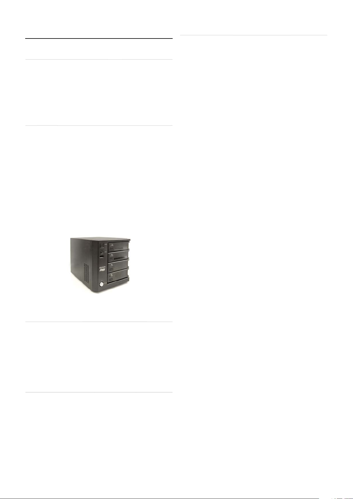
The Verbatim PowerBay NAS array provides four disk cartridges
confi gurable in various RAID levels for superior performance and data
redundancy. The PowerBay NAS array enables you to share documents,
fi les, and digital media such as music, photos, and video with everyone
on the home or offi ce network. Remotely accessing fi les through the
Internet is also possible with the built-in FTP server. Whether you are
allowing access locally or over the Internet, keep data safe by giving
access rights only to specifi c users or groups.
When con
and groups and assign them to folders with either read or read/write
permissions. This is ideal for an offi ce environment with employeespecifi c sensitive data or for the home network. The PowerBay NAS
array will be available to any computer (PC, MAC, or Linux-based)
on your network, without the need to install any software on the
computer.
Package Content
• Verbatim PowerBay 4-Bay NAS array
• Front Pane
• A
•
• CD-ROM containing software and documentation.
• Quic
guring the PowerBay NAS array, you can create users
Lock Key
Power Cord
AT-6 Network Cable
Installation Guide
Features and Benefi t
he Verbatim PowerBay NAS array supports 4 hard drive cartridges
and includes the product features listed below:
• Equipped two 10/100/1000 Mbps Full/hal
Gigabit Ethernet ports
• Embedded four internal SATA II 3.5” HDD interface
• Two access modes su
no setup necessary in open mode.
• Supports Magical Finder utility (Windows 2000, Windows XP,
Windows Vista, and Windows 7
• Supports confi guration fi le save/loa
• DHCP Client
• LLTD for Vista 32/64-bit
• CIFS/SMB for Windows
• NFSv2/v3 for Linux and UNIX
• AFP 3.1 for Mac O
• Active Directory support for Windows Server 2008
• EXT2
• FAT32 (R/W) and NTFS (Read only) for External USB drive
• FAT32 (R/W) and NTFS (Read onl
• 256-bit AES disk encryption
• Unicode Suppor
• Power Saving (Disk idle spin-down)
•
•
•
• Public Folder
• Support
•
• Users can be assigned to multiple Groups
• Scheduled Backu
• Rea
• Sc
• eSATA Backup (copy fi les from attached eSATA drive to NAS)
• USB Backup (copy
•
• Em
• NTP Server
• Print
• Externa
• UPS monitoring
Internal hard drive forma
utomatic power recovery
cheduled Power On
hare Folder Level Permission
or Users and Groups
ser share Folder Quota Contro
time LAN Backup
LAN Backup (Replication by Rsync
ystem status
il alert
erver
Storage device via USB or eSAT
orted: Open mode and Account mode,
rom PC to NAS
les from attached USB drive to NAS)
-duplex auto-MDIX
or eSATA devic
System Requirement
For best results, the following system requirements are
r
• Com
available space / CD-ROM Drive
• Current web browser, such as Internet Explorer, Mozilla Fire
or Safar
• Gigabit Ethernet router or switch
• Windows XP
igher, or Linu
:
uter with: 1GHz Processor / 512 MB RAM / 200MB
Windows Vista, Windows 7, Mac OS X 10.2 or
ox
Page 4
Hardware Overvie
w
ew
T
.
ff.
.
f
US
.
.
)
)
n
/500
g
.
.
us.
n
l
n
d
.
D
y
y
e
)
.
y)
f
f
e
f
g
500TW
05
B
500
s
2
f
s
.
r
d
on
Th
.
f
.
f
ff
gaby
.
s
T
U
’
assword is blank
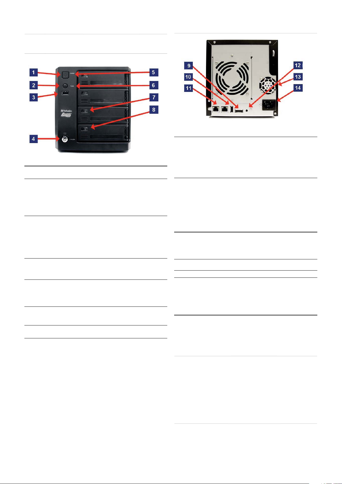
Front Vi
MPONEN
. Power Button • Press to power on
. Function Button USB One-Touch-Copy function is available when a USB storage
. USB Connector • One USB 2.0 (Type A) connector: USB Host port for
4. Cartrid
e Key Lock • Turn key counterclockwise to the Lock position to lock all
. Power LED The power button contains a colored LED to indicate power
. Status LED • Solid Green = Device operational status is Norma
7. Cartri
ge Lock • Slide locking button to the left to lock each cartridge
. Cartridge LE
DESCRIPTION
• Press and hold for more than 5 seconds to power o
device is connected to the PowerBay NAS array
• Press momentarily to initiate fi le copy from external USB
storage device to the PowerBay NAS array.
• Press and hold
the external
• When alarm buzzer is sounding, press button to cancel alarm.
connecting an external USB storage device
• Supports USB backup (copy fi les from attached USB drive to
NAS array
• Provides additional storage as a shared volume on the LAN
default name “USBDisk_1”
• Supports USB Unlock Key for use with disk encryptio
• Power: 5V
cartridges in place
• Turn key clockwise to the Unlock position to unlock all
cartridges
tat
• Solid Green = Device is Powered O
• Solid Red = Device is in Standby Mode with AC power
applied
• Blinking Green = Device is starting up or shutting dow
• Solid Red = Device Error
• Slide locking button to the right to unlock each cartridge.
Each HDD cartridge locking button contains a colored LED to
indicate disk status:
• Solid Blue = Disk Read
• Blinking Blue = Data Access Activit
• Blinking Red = Disk Error
• Solid Red = When all 4 cartridge LEDs are red indicates
Locked Encrypted Volum
or more than 3 seconds to safely unmount
B device
mA max
ear Panel (Connections
MPONENT DESCRIPTION
. eSATA connector • One SATA-II (eSATA) connector for connecting external
10. USB Connector USB Host Port. One USB 2.0 (Type A) connector; Power:
11. RJ-45 Connectors Two Gigabit Ethernet ports.
1
. Reset Button • Press and hold for more than 5 seconds to reset confi guration
13. Cooling Fans • Exhaust ports for two cooling fans are provided
14. AC Power
onnecto
storage device
• Supports eSATA backup (copy fi les from attached eSATA
drive to NAS arra
• Provides additional storage as a shared volume on the LAN
ault name “eSATA_1”)
(de
• Supports mirror
eSATA driv
5V/500mA max. Used
• USB Printer; or
• USB UPS Monitor. If the attached UPS detects a power failure,
an automatic shutdown of the NAS array will be initiated by use
of this feature. Compatible with the following UPS equipment:
- APC BACK-UPS ES BE
- Powerware PW-31
- Tripp-Lite SMART550US
- Phoenixtec A-
• Port 1 (LAN): For connecting the PowerBay NAS array to LAN.
This port supports Wake-On-LAN function.
• Port 2 (EXT): For real time backup to another PowerBay NAS
array
to
actory default setting
• For AC power cor
unction between NAS array and attached
or connectin
Plu
Installati
is section will walk you through the installation process. Placement
of the device is very important. Do not place the device in an enclosed
area such as a closet or cabinet
Before You Begin
Please read and make sure you understand all the prerequisites
or proper installation of your new device. Have all the necessary
information and equipment on hand before beginning the
installation
Note: Capacity dependent on model. 1 MB = 1,000,000 bytes / 1 GB = 1,000,000,000
bytes / 1 TB = 1,000,000,000,000 bytes. Some capacity used for pre-loaded software,
ormatting and other functions, and thus is not available for data storage. As a result,
and due to di
me
ering calculation methods, your operating systems may report as fewer
tes/gigabytes/ terabytes
Default Setting
he default values for the PowerBay NAS array are as follows:
•
ser Name is ‘admin
• P
Page 5
• LAN IP Address is 192.168.0.
32
0
n
p
pp
p
.
p
g
pp
y
.
f
-
-
f
h
ll
f
92
f
f
”.
.
ool described
sectio
y
g
f
.
p
T
f
e.
y
W
f
p
h
p
fi
.
• LAN Subnet Mask is 255.255.255.
more advanced users may choose to confi gure name servers (such
as WIN servers or DNS servers) in order to access the PowerBay NAS
array from a different subnet
actory Reset Butto
The device can be reset to the original factory default settings by using
a ballpoint or paperclip to gently push down the reset button in the
following sequence:
1. Ensure the device is
2. Press and hold the reset button for a
3. The factory reset process should take around 1 to 2 minutes.
Remember that this will wi
including user account information and LAN IP settings
owered on.
roximately 5 seconds.
e out any settings stored in fl ash memory
Basic Installation
Hardware Setu
This section provides unpacking and installation information for the
PowerBay NAS array. Open the shipping carton for the PowerBay NAS
array and carefully unpack its contents.
1. Ensure that a hard drive cartrid
four mounting racks and that the cartridge locking buttons are in
the left (locked) position.
2. Connect the su
the back of the device. Connect the other end of this cable to
our network, either via a switch/router or via direct connection
to your computer for confi guration.
3. Connect the supplied power cord to the rear of the PowerBay
NAS arra
4. Press the Power button on the front of the PowerBay NAS array.
The green status LED will begin to fl ash to indicate that the unit
as initiated the power-on sequence.
5. Wait
a. DHCP client is enabled by de
b. I
6. A
7. Before you can see any PowerBay NAS array shared folders, you
To set up other user accounts, and to confi gure other basic system
settings, you should continue setup using the web-based administration
t
Once the PowerBa
been confi
rom any computer within the same subnet on your LAN. Furthermore,
or the PowerBay NAS array to boot up and to auto
confi gure its connection on the network. Depending on your
articular LAN confi guration and settings, this may take several
inutes. The following protocols will be followed during auto
confi guration:
er LAN equipment that is providing the DHCP service will
or ot
automatica
and complete the network connection.
no DHCP server is available on your network, then
the PowerBay NAS array will take its default IP address of
1
.168.0.32.
ter successfully connecting to your network you will be able
to discover the PowerBay NAS array on your network. Its de
ame is “PowerBay
ust fi rst set up user accounts, or at a minimum must assign
ead/write privileges for the default folder named Volume_1.
This process is explained further below. Once this is done, you
ill be able to discover shared folders in network workgroup
amed “Workgroup”. In Windows go to My Network Places /
Entire Network / Microsoft Windows Network / Workgroup, or in
Mac OS X navigate to Go / Network
ured for your network environment, it can be accessed
lied Ethernet cable to the LAN port located at
and to an AC power receptacle
y assign an IP address to the PowerBay NAS array
in the next
NAS array is connected to your network and has
e is inserted into each of the
ault. Therefore, your router
ault
n.
Software Setu
he included CD-ROM contains copies of the User Guide, as well as
tware applications: 1) MagicalFinder, and 2) Acronis backup
two so
ftwar
agical Finder - Network Setup Utilit
hen fi rst powered on, during the initial boot sequence, the PowerBay
NAS array will wait to be assigned an IP address via DHCP. If it does
not receive a DHCP as¬signed IP address, by default it will have a selfassigned IP address of 192.168.0.32.
If your router assigns addresses automatically, your router’s manual
ill describe how to view the DHCP Lease List so you can see your
drive’s assigned IP address. Alternatively, you can fi nd your drive’s IP
address using the included Magical Finder utility that is provided on
the product CD. If you are unfamiliar with the operation of your router,
you may fi nd it easier to use the Magical Finder.
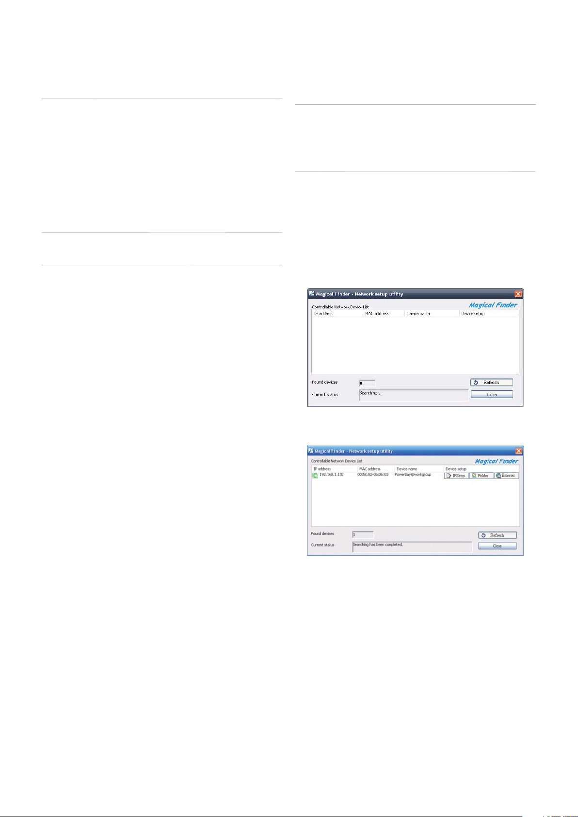
1. Open the Magical Finder Utility and allow it to search for the
PowerBay NAS array.
2. After fi nding the PowerBay NAS array the utility will list the
device’s IP address, MAC address and Device Name. (I
device is not listed on the initial scan you can press the Refresh
utton to initiate a Re-Scan)
You have three o
• IP Setup Button: To enter t
• Folder Button: To o
• Browser Button: To link to the device web con
tions:
e IP Address Setup.
en Windows Explorer to \\PowerBay.
the
guration
5
Page 6
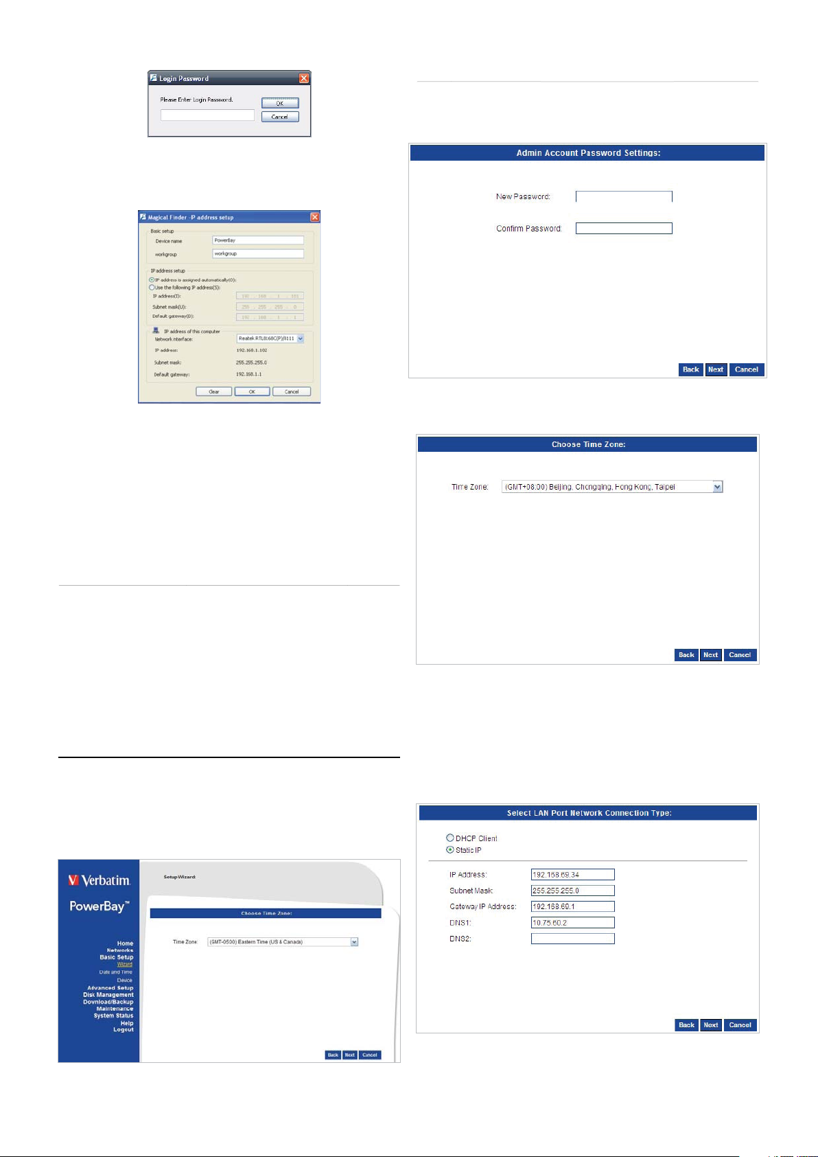
3. After clicking the IP Setup Button you’ll be prompted to enter the
y
f
fi
p
g
.
he b
W
s
d
.
ce.
l
lly
ll
y.
oose
password (The default password is blank) and click OK.
4. Here you can change:
Device Name - Network name of the PowerBa
Workgroup - Workgroup name o
IP Address Setup - Edit the IP to
Network Interface - Your network ada
After the chan
es you can click OK to apply the changes
your network.
t your network.
NAS array.
ter.
izard Page
1. When initiating the Wizard, the user will always be prompte
to re-enter the login user name and password as a security
measure. Do so and click the next button
2. In this window the user can change the time zone confi guration
f the devi
Acronis Backup Software
Acronis backup software is included on CD-ROM. To install this
application on one of your client Windows computers, open the
Acronis folder on the CD and then double click the setup fi le to start
installation. The Acronis installation window will appear. Follow the
setup wizard to install the software. To backup fi les to your PowerBay
NAS array using Acronis, you must fi rst assign a drive letter to your
tination folder.
Web Confi guration
The PowerBay NAS array has a web based confi guration tool. You can
access the confi guration tool by selecting the Browser Button of the
Magical Finder as described above, or by opening your browser and
entering the PowerBay NAS array IP address. The confi guration tool
includes a setup Wizard that allows you to quickly confi gure some of
t
asic device settings. Click “Wizard” to start the Wizard setup.
3. In this window the user can change the IP confi guration of the
LAN Port of the device. You can choose:
• DHCP C
automatica
network).
• Static IP - A
manuall
ient - Allows an IP to be assigned to the device
(this option requires a DHCP Server in your
ows you to assign an IP address to the device
4. In this window the user can change the IP confi guration of the
EXT Port of the device. You can ch
:
6
Page 7
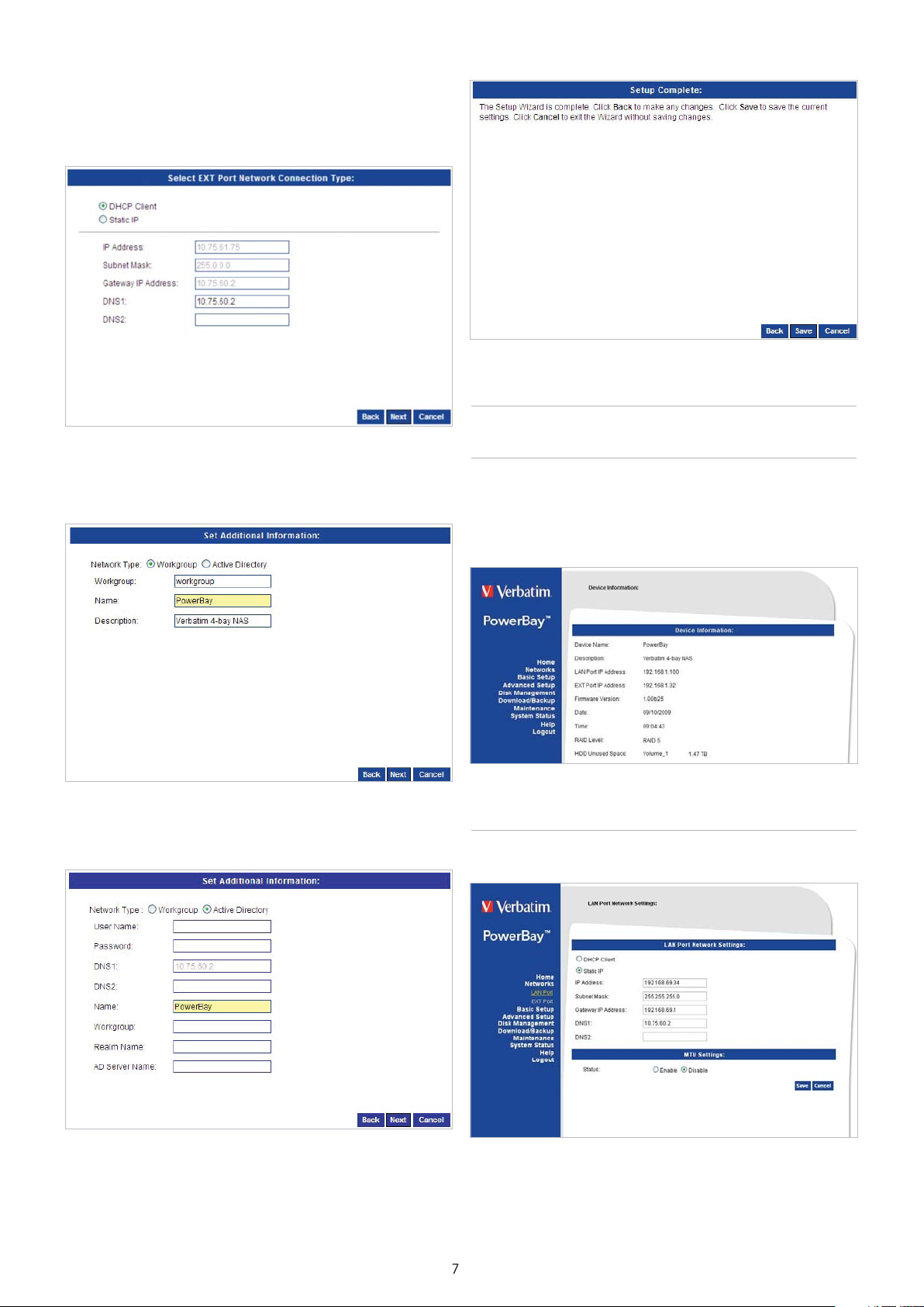
• DHCP Client - Allows an IP to be assigned to the device
lly
y.
th
f
.
T
.
n
T
.
automatica
etwork).
• Static IP - Allows you to assign an IP address to the device
anuall
(this option requires a DHCP Server in your
Home - Section
5. In this window you can confi gure the Workgroup settings for
your device. If you have Active Directory confi gured in your
etwork you can choose the Active Directory option to setup
ose settings.
6. In this window you can confi gure the Active Directory settings
or your device
evice Information - Page
he Device information page allows you to view basic information
about the setup of the device. Here you can see the current settings for
Device Name, Description, LAN Port IP Address, EXT Port IP Address,
Firmware Version, Date, Time, RAID Level, and HDD information
Networks - Sectio
he Local Area Network settings for the device can be confi gured on
the LAN Port page
7. In this window you can complete your setup. Click the Save
Button to save your settings.
Page 8
Port - Page
f
.
f
he d
.
ge
.
y
.
e serve
T
h
T
f
f
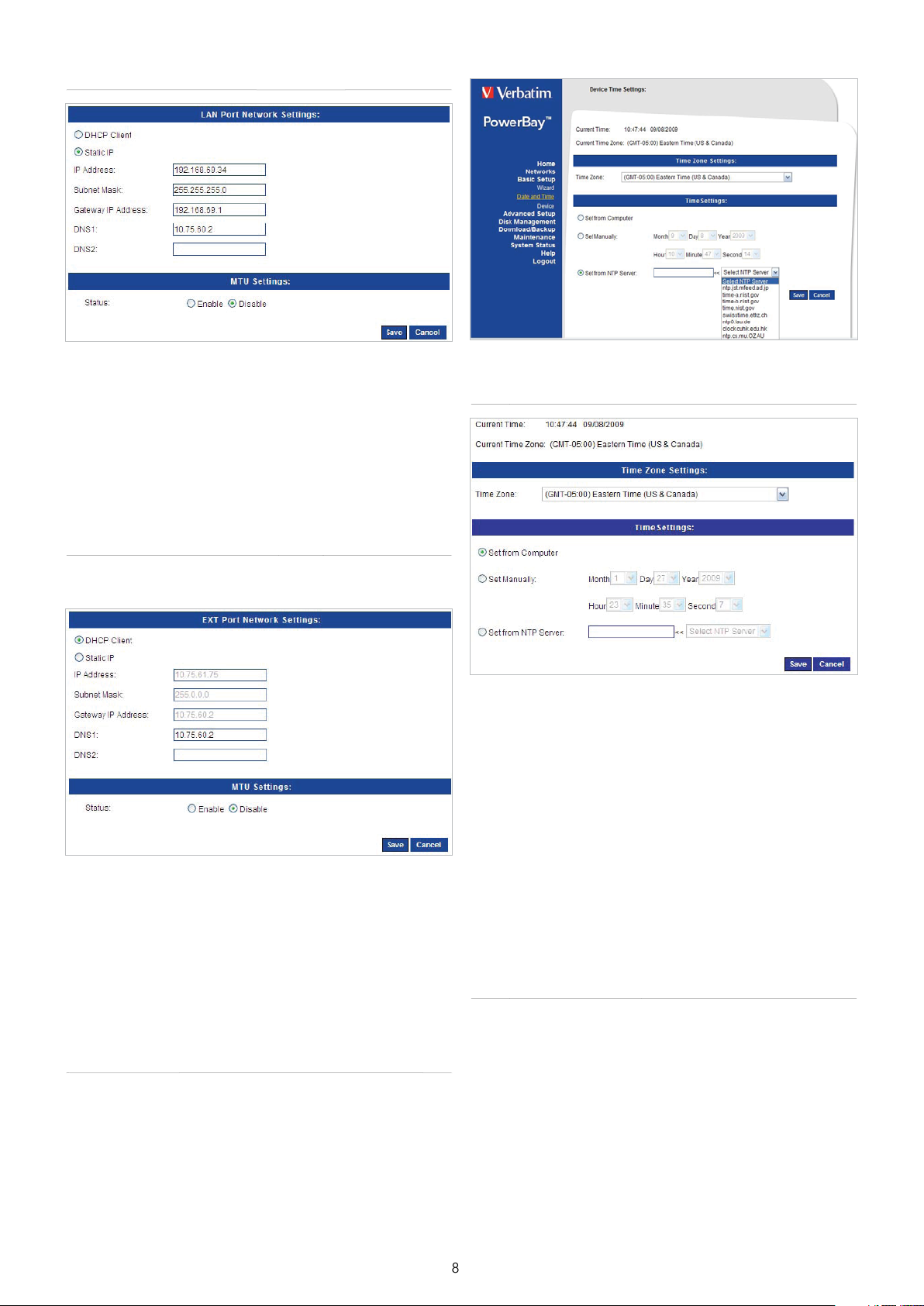
DHCP Client: Selecting DHCP Client will cause the device to obtain an
IP address from the local DHCP server.
tatic IP: Selecting Static IP requires you to assign the IP information for
the device manually.
MTU: The de
your network supports Jumbo Frames you can specify larger frame
sizes (in the range of 3000-9000) by fi rst selecting Enable in the MTU
Settings dialogue.
ault MTU (maximum transmission unit) is 1500 bytes. If
ate and Time - Pa
EXT Port - Page
The Local Area Network settings for the device’s EXT Port can be
confi gured on the EXT Port page
DHCP Client: Selecting DHCP Client will cause the device to obtain an
IP address
tatic IP: Selecting Static IP requires you to assign the IP information for
t
your network supports Jumbo Frames you can specify larger frame
sizes (in the range of 3000-9000) by fi rst selecting Enable in the MTU
Settings dialogue.
rom the local DHCP server.
evice manually.
: The default MTU (maximum transmission unit) is 1500 bytes. If
Basic Setup - Section
The Time and Date of the device’s internal clock can be set manually or
be set automatically from the client computer or using an NTP Server
Time Zone: Choose the Time Zone of where you are located from the
drop-down menu.
et from Computer:To set the internal clock of the PowerBay NAS array
to the same time as the client computer, select Set from Computer and
it Save
et the Date and Time Manually: To set the date and time manually,
select Set Manuall
menus. Press Save to save the new settings
NTP Server: Tick the Enable NTP Server checkbox to enable NTP.
Network Time Protocol (NTP) synchronizes the device with an Internet
tim
ype the URL of the NTP Server in the NTP Server checkbox or use the
drop-down menu to choose one of the default time servers listed for
your convenience. Press Save to save t
r.
, and fi ll in the date and time using the drop-down
e new settings.
evice Settings - Page
he device settings page allows you to confi gure the Workgroup or
Active Directory settings o
I
your network is confi gured as a Workgroup, click the Workgroup
radio button. Confi gure the parameters as described below:
your network on the device.
Page 9

Workgroup: The Workgroup is used by Microsoft Windows Network to
e
p
p
h
y
f
fi
h
ssword
.
AD S
ge
T
T
.
T
f
.
T
e”.
Th
f
d
d
.
organize available network groups within the same network.
Nam
: The unique Name appears for other network services including
shared libraries on iTunes and other media players. The name can be
used to access your device from a web browser instead of using an IP
address, for ex¬ample, http://powerbay.
By default the device name is “PowerBay”.
Descri
tion: This fi eld assigns a device description to help identify the
device in the workgrou
If your network is confi gured in an Active Directory make sure the
following conditions are true:
1. Ensure t
and Active Directory server will only tolerate a maximum time
difference of 5 minutes.
2. Ensure that
rom the DNS server. The DNS1 and DNS2 settings are the same
as the LAN Setup. Please make sure this is working properly.
To con
the Active Directory radio button and confi gure the parameters as
described below:
ser Name: Input the user name of an account setup on the Active
Directory t
Pa
account.
ame: Input a Domain Name Service (DNS) name for the PowerBay
NAS array. If the device connecting to the PowerBay NAS array is a
rowser or logon server this will be the name that these services are
advertised by.
Workgroup:
name should be the same as the computers on the network. Devices
using the same workgroup will have additional fi le sharing methods
available
Realm Name:
Active Directory Domain in this fi eld. This option specifi es the Kerberos
realm to use.
erver Name: Input the name of the Active Directory Server in this
fi eld. When the Windows user attempts to access the device at login
at the Time and Date is synchronized between the
evice and the Windows Active Directory server. The device
ou can get the IP address of the 2008 AD server
gure the PowerBay NAS array to use Active Directory, click
at requires access to the resources on the device.
: Input the password of the chosen Active Directory user
nter your Workgroup name here. The workgroup
nput the FQDN (Fully Qualifi ed Domain Name) of the
time, the device will connect to the 2008 AD Server and attempt to
authenticate the given user with the given password.
anguage Settings - Pa
he web based confi guration tool for the PowerBay NAS array is
confi gured at the factory to use English as its user interface language.
he language settings page allows you to select a different user
interface language
elect Language: To use a different user interface language select an
available option from the pull-down list. Click ‘Save’ to apply the new
anguage selection.
Advanced Setup - Section
he PowerBay NAS array keeps track of data stored by its network
users by managing the data’s destination folder (also referred to herein
as a “shared folder” or simply a “share”). Furthermore, the PowerBay
NAS array must keep track of who may read from, and write to, each
older. It does this by setting up user accounts and groups. A group is a
collection of specifi c user accounts. When you assign access privileges
to a new share you have the option of either making assignments for
individual user accounts, or for an entire group of users at once by
referring to the group’s name
he default factory settings provide for no default user accounts or
default groups. Though there is one default folder (named Volume_1),
this folder has no default access privileges and so will not be accessible
at fi rst. The simplest way to make the Volume_1 folder accessible is to
use the web confi guration tool (Advanced Setup / Shared Folders) to
defi ne the Volume_1 folder privileges as “Allow everybody read and
rit
e Users/Groups menu is used to create and manage user and group
accounts. These are used
specifi ed fold¬ers on the network drive (using the Network Access
menu), or to setup FTP access an
connecte
created. When the device is connected to an Active Directory a
combined total of 10000 users and groups can be displayed. By
default all users have read and write access to all newly created folders,
ut access rules can be created in the Network Access menu
to a Workgroup up to 128 users and 10 groups can be
or user access and read/write privileges for
privileges. When the device is
Page 10

0
Users - Page
l
y
g
.
.
fi
p
fy
g
.
ld
S
T
e
T
.
g
T
oca
ocatio
.
ser Creation: This section contains required attributes for a new user,
including group, user name and password.
Se
ect User and enter a user name, password and then click Add.
ser List: Displays the list of users that you may assign to the selected
group.
To modif
modify button.
To remove a user from the
remove button
a user to the selected group, click the user and then click the
roup, click the user and then click the
Groups - Page
Create new groups that users can be assigned to and assign hard drive
space quotas for groups
User/Groups: Select the users or groups and assign Read Only or
Read/Write permissions to them.
Fo
er:
elect the folder to assign to the nominated users/ groups and
click on the Add a
hared Folder List:This section displays a list of existing Shared
Folders. To modify a share’s attributes, click the share and then click
the Modify button.
o remove a share, click the share and then click the Delete button.
hared Folder button.
uotas - Pag
his section allows you to assign a quota to a group or user to limit the
amount of storage they are allocated. By default, users and groups do
not have a quota
Disk Quota Status: This option enables or disables disk quota option.
roup Creation: This section contains required attributes for managing
roups. To create a new group enter the Group Name, select the
c Users you want to be members of the group, and then click
speci
Add a Group.
Grou
List: This section displays the list of existing groups.
To modi
To remove a
a group, click the group and then click the Modify button.
roup, click the group and then click the Delete button.
Shared Folders Settings - Page
Create shared folders for users and groups on the local network
User Quota Settin
can modify the each user’s quota here. Note that the default value is
nlimited.
hared Folder Quota Settings: This section allows you modify the
quota for a specifi c shared folder.
TP Server - Page
he device is equipped with a built in FTP Server. The server is easy to
confi gure and allows users to access important data whether they are
n the l
confi gured to allow user access to specifi c directories, and will allow
up to 10 users to access the device at a time
s:This section will list the existing users and you
l network or at a remote l
n. The FTP server can be
1
Page 11

FTP Server: This option allows the user to enable and disable the use
S
sconnected
g
p
y
y.
f
guag
f
.
os
fi
olde
h
is
Th
.
.
olde
olde
h
.
e
.
AFP
.
of FTP Server on the device.
Max User: Sets the maximum number of users that can connect to the
erver at once.
FTP
Idle Time: Sets the amount of time a user can remain idle before being
i
Por t: Sets the FTP port number. The default is port 21.
In order to use FXP (File Exchan
transfer, please make sure to change the port from 21 to some other
ort as listed in the Port section of the web UI. Also, please make sure
to o
from
Flow Control: Allows you to limit the amount of bandwidth available
or each user.
Client Lan
support Western European codepage when transferring fi les. Support
has been added for non standard FTP clients that are capable of
supporting these character sets.
.
e Protocol) for server-to-server data
en the corresponding port on your router and forward that port
our router to the PowerBay NAS arra
e: Most standard FTP clients like Windows FTP, only
NFS Server - Page
This section allows you to enable the built-in NFS server to share your
olders by NFS
sync Server - Page
is section allows you to set up your Rsync Server
Rsync Server: Enable or disable the Rsync Server.
ser Name: Enter the User Name allowed to connect to this Rsync
erver
Password:
Rsync Server.
F
ub-Folder: Enter the name of sub directory. It will be created under
“F
ared Name: Enter the shared name for the Folder.
Rsync S
in the Rsync folder
nter the Password used for the user to connect to the
r: Select the directory available to the Rsync Server.
r”.
ared Folder List:This section lists the existing shared folders
NFS Server Allowed: Enable or disable the NFS Server.
H
t: Enter an IP address of NFS clients, the fully qualifi ed domain
name, netgroups or IP networks. This
r: The folder you want to export to NFS clients.
F
Root Squas
anony¬mous User ID/Group ID.
L
t: This section lists information about the confi gured NFS clients.
It includes Allowed Hosts, Paths, Root Squash, and Read/Write
permissions.
NFS Client: Map requests from User ID/Group ID 0 to the
eld also supports wildcards.
AFP - Pag
Apple Filing Protocol (AFP) provides fi le services for Mac OS X and
original Mac OS. This implementation is compatible with AFP 3.1,
ich was introduced in Mac OS X Server version 10.2
: Select Enable or Disable to turn AFP on or off. It is disabled by
lt.
Once Enabled is checked, related protocol parameters must be
selected
Mac Codepages: Select a codepage which is used by your Mac OS
9. If your environment only has Mac OS X, you can ignore this setting.
11
Page 12

Time Machine: Enable or di
sable
:
e
)
ff.
e
T
f
.
.
enabled, you must enter a login password and the amount of storage
(in gigabytes) that you want to allocate for this service.
AppleTalk
PowerBay NAS array to be discovered by Net Browser on Mac OS 9.
Enable or disable AppleTalk. AppleTalk allows the
the Time Machine service. If it is
LLTD - Pag
Link Layer Topology Discovery (LLTD) allows the PowerBay NAS array to
be discovered by Windows Vista’s network map. (Note: Enabling LLTD
may cause decreased network performance. If you are experiencing
decreased network performance try disabling LLTD.
: Enable or Disable to turn LLTD on or o
Disk Management - Section
Disk Status - Page
This page displays the status of all of installed disk cartridges of the
PowerBay NAS array, as well as any attached USB or eSATA drives.
isk Confi guration - Pag
he PowerBay NAS array supports fi ve RAID methods of disk
confi guration. They are RAID 0, RAID 1 with spare, RAID 5, RAID 5 with
spare and RAID 6. When choosing to use RAID with spare the spare
isk’s icon will change its color to green.
Each o
the RAID modes may be further confi gured to include full disk
data encryption. RAID modes 0, 5, and 6 may be further confi gured to
included array mirroring to an attached eSATA drive
WARNING: Changing RAID mode will delete all data on the disks. Do not change the
RAID confi guration unless you have fi rst saved all of the data from the device to another
storage location
12
Page 13

3
RAID 0: RAID 0 (also called Striping) distributes data across all disks
p
:
.
lly
.
e
T
f
W
).
f
fi
.
n
T
.
fi
g
:
.
fi
fi
f
f
f
fi
.
in a way which can improve throughput, while retaining full capacity.
However, RAID 0 provides no fault tolerance so in case of possible
failure of any disk, all data will be lost. Available capacity is the
combined capacity of all four disk cartridges.
RAID 1 with S
are: RAID 1 (also called Mirroring) stores a duplicate set
of data onto at least one other disk so that if one disk fails, all data can
be recovered from the other disk. The PowerBay NAS array implements
RAID 1 in a way that provides for even more redundancy, resulting in
maximum fault tolerance. It does this by (a) using two drives as mirrors
instead of just one, and (b) using the fourth drive as a spare. The spare
drive will automatically rebuild as a fresh mirror whenever a failure of
one of the other three drives is detected. Available capacity is equal to
that of only one disk cartridge.
5: RAID 5 (Striping with distributed parity) combines three or
more disks in a way that protects data against loss of any one disk. The
storage capacity of the array is reduced by one disk. The PowerBay
NAS array implements RAID 5 in one of two ways
1. Select “RAID 5” to build a 4-disk array. Available capacity will be
equal to that of three disk cartridges
2. Select “RAID 5 with Spare” to build a 3-disk array. The fourth disk
is used as a spare. The spare drive will automatica
rebuild to
complete a healthy 3-disk array whenever a failure of one of the
other three drives is detected. Available capacity is equal to that
of two disk cartridges.
6: RAID 6 (Striping with distributed dual parity) combines all four
disks in a way that protects data against loss of any two disks. In the
event of a single disk failure, the use of dual parity allows for time to
rebuild the array safely without the data being at risk if an additional
drive fails before the rebuild is complete. Available capacity is equal to
that of two disk cartridges
Array Mirroring to eSATA Driv
he full data of the PowerBay NAS array can be continuously copied
to an attached eSATA drive. If a catastrophic failure of the NAS array
occurs, the full data can be restored from the eSATA drive once the
NAS array has been repaired or replaced. Array mirroring to eSATA
is supported only in RAID modes 0, 5, and 6 and is NOT supported in
RAID 1 with Spare or in RAID 5 with Spare. The capacity of the eSATA
drive must be at least as large as the capacity of the NAS array.
I
you want to use this function, please enable it during the fi rst time
you confi gure the array.
hen the mirror function is in use, the Disk Confi guration page will
show the status of the mirror system, and will present action buttons
to temporarily disable the mirror function (“Unmirror” Button) and to
restore data from the eSATA drive to the NAS (“Restore” Button
WARNING: When using the eSATA mirroring function, you MUST attach and power
up the eSATA drive BEFORE you power up the PowerBay NAS array. This power-up
sequence must be
power up the PowerBay NAS array
the eSATA drive will not be recognized as a mirror device, so the eSATA drive will no
onger be synchronized to the NAS data
ollowed EACH TIME you power cycle the PowerBay NAS array. If you
rst, and later attach and power up the eSATA drive,
Array Encryptio
he PowerBay NAS array supports 256-bit Advanced Encryption
Standard (AES) full disk encryption. Encryption may be enabled for
any RAID mode. If eSATA mirroring is enabled, then data copied to the
eSATA drive will also be encrypted
If you want to use this function, please enable it during the fi rst time
you con
Once the drive has been confi
thereafter be LOCKED or UNLOCKED using a password key. When the
array is LOCKED it will not show up on the LAN as a shared volume and
users cannot access it for storage. All four cartridge LED’s will remain
red while the array is LOCKED. For convenience, several methods are
provided to UNLOCK a LOCKED array
1. Enter the NAS user interface and press UNLOCK on the Disk
2. Insert a USB Key device into the front USB port of the PowerBay
3. Enter the NAS user inter
gure the array.
ured using encryption, the full array can
Confi guration page. You will be prompted to enter the password
ey string
NAS array. This Key device may be either a fl ash drive or a hard
drive, and must have been previously con
gured with the key
le using the ‘Store Key in USB Drive’ procedure. Once the array
is unlocked, the USB Key device may be removed.
ace and load the key fi le from a
computer on the LAN using the ‘Load”
unction on the Key
Management page. This key fi le must have been previously
stored onto the computer using the ‘Save’
Management page. Alternatively, the key
unction on the Key
le might have been
previously e-mailed to a user using the ‘Mail’ function on the Key
Management page.
NOTICE: When encryption is enabled, data transfer rates may be reduced
1
Page 14

Enable / Disable Encryption: During disk confi guration, select Enable
.
:
y
.
.
fi
s.
e.
y
.
.
.
y.
f
y
.
or Disable. If Enable is selected, you will be prompted to enter a
assword key string. Also you may optionally select one of two
additional encryption options
Password Key: Enter a password key string of 6-10 characters.
Auto Unlock During System Reboot
Check the Auto Unlock box if you want the NAS always to power up in
the UNLOCKED state. Use the feature with caution, since anyone who
can access the PowerBay NAS array to power it off and back on can
unlock a locked array.
Store Ke
unlock a locked array, insert a USB Flash Drive or USB Hard Drive in the
front USB port and check this box. An encrypted key fi le will be written
to the USB device during confi guration. A USB key device created in
this way can later be used to UNLOCK a LOCKED array. The USB key
cannot be copied, although multiple USB keys may be created from
the Key Management page
Press ‘OK’ to initiate drive reconfi guration. This process erases all data
on the array
in USB Drive: If you want to use a USB storage device to
Key Management: Use this page to defi ne how you want the password
key to be used for unlocking the encrypted array
‘Change’ allows you to enter a new password key
‘Save’ and ‘Load’ allow you to store an encrypted key fi le “Volume_1.
key” onto a computer on the LAN, and later retrieve the fi le to UNLOCK
a LOCKED arra
‘Mail’ allows the password key string to be e-mailed to all users whose
e-mail addresses have been entered into the Receiver E-mail fi elds
on the E-mail Settings page. If the administrator forgets the password
key, the administrator can recover the key by mailing it to himself. This
eature also means that anyone who discovers the administrator’s User
Interface password can also easily discover the encryption key.
‘Auto Unlock’ and ‘USB Ke
gives you a chance to invoke these options after you have confi gured
the array
’ options are offered again on this page. This
Managing the Encrypted Drive: Once the NAS array has been
encrypted, the Disk Con
tton
‘Lock’ will LOCK the array. You will be prompted to enter the password
key string to continue. A locked array will not show up on the LAN as a
hared volum
‘Unlock’ will UNLOCK the array. You will be prompted to enter the
password key string to continue.
‘Ke
Management’ will present options for managing the password
key
‘Reconfi gure’ will still allow you to reconfi gure the array, although now
ou will be prompted to enter the password key string before you can
ntinue.
guration page will show three additional
14
Page 15

5
Disk Confi guration – Page (Steps)
.
.
.
f
T
e
:
efo
f
f y
.
Here are the steps to confi gure all the hard drives (including an
attached eSATA mirroring disk) to run on RAID 6
tep 1: Select the desired RAID confi guration. In the example we
chose RAID 6
tep 2:
elect the desired fi le system format. In the example we chose
ext2.
tep 4: You will be warned that doing this confi guration will erase all
the data from your hard drives. Click OK (if you want to proceed).
tep 5: The RAID confi guration will start. Please wait for it to complete
ully before proceeding.
he new RAID settings will now show on the Hard Disk Confi guration
page, including the change of the eSATA Disk’s status to “Synchronized”.
If you select “Unmirror” but leave the external eSATA drive powered
on and connected, the Status will change from “Synchronized” to
“Connected”. To restore all data from the external eSATA drive to the
NAS, hit the “Restore” button. The external eSATA drive capacity must
be at least as large as the currently confi gured NAS RAID array.
Step 3: Decide whether you want to attach an external eSATA drive
for dedicated use in saving a full duplicate of the data stored on your
PowerBay NAS array. If you choose to use this eSATA Disk Mirror
feature, check the Mirror option button located below the eSATA Disk
icon in this dialogue. When the mirror feature is enabled, the eSATA
Disk icon will have a blue frame around it. The eSATA Disk Mirror
option is not available for the two RAID modes using a spare.
lick OK
isk Utilities - Pag
.M.A.R.T. Test
S.M.A.R.T. (Self-Monitoring, Analysis, and Reporting Technology) is
a monitoring service that can diagnose the health status of a disk by
analyzing certain disk attributes. The test result for each disk is shown
at the right.
can Disk: Press the Scan Disk button to initiate a scan of all disks and
attempt to detect and to list any errors found. This process can take a
long time to complete.
R
rmat: If you want to reformat the array, using the currently selected
RAID mode, you may press the Reformat button. You will be warned
ormatting will erase all the data from your hard drives. Click OK
that re
(i
ou want to proceed)
1
Page 16

6
Power Management - Pag
e
y
.
he hard d
fi
.
.
ead tas
p
.
edule a Patro
ead task de
n
.
e
T
fi
f
)
e
T
fi
.
Enabling this feature will cause the hard disk drives to hibernate after
the specifi ed time of inactivity. The hard disk drives will wake-up when
new activit
is detected
Download/Backup - Sectio
Download fi les from a FTP server or web server or Backup shared fi les
and folders from computer or NAS
Power Management:
Turn Off Hard Drives: Select the amount of idle time allowed before
t
powered on, only the hard drives lose power. They will regain power
immediately after attempting to access them.
Click ‘Save’ when
rives are shut down. Remember that the device will stay
nable or Disable power management.
nished
Patrol Read - Page
The Patrol Read function launches a daemon that runs in the
background to actively search disks for unreadable and mismatched
blocks. If any problem is detected, the daemon will attempt to correct
it in an effort to prevent potential data corruption. This procedure
should be scheduled for off-peak usage periods. If the system is shut
down before the Patrol Read procedure completes successfully, it will
not start automatically after the system is rebooted. In this case you
ave the option to access the Patrol Read page and restart it manually
by pressing the Start button
TP/HTTP - Pag
Pat rol Read Status: The current status of an active Patrol R
e shown under Status. Future tasks that have been scheduled will be
isted in the Schedule List.
Use the Start or Sto
read activity. Pressing Stop will immediately stop a Patrol Read that is
underway. Pressing Start will start a new Patrol Read or will restart a
Patrol Read that had previously been interrupted
Create Schedule: To sch
parameters under Schedule, and press Create.
button to manually override the scheduled patrol
l R
fi ne the time
k will
Login Method:
contains the fi les you wish to schedule for download. If no password
is required, choose ‘Anonymous’. If a password is required, choose
‘Account’ and provide the login name and password.
ype: Select either ‘File’ or ‘Folder’ from the drop down list depending
on what you plan to download. Choose File if downloading a specifi c
le. Choose Folder if downloading all fi les in a specifi c folder.
RL: Enter the FTP, HTTP, or Local site address for the scheduled
download. Click on Test to verify access to the site address and fi le/
older. Click on Local to browse for a folder from the internal drives. If
you have chosen ‘File’ from the above drop down list, you must specify
the exact fi le in the URL path. This includes the fi le extension. (e.g.
http://example.com/test/testfi le.txt
ave To: Enter the specifi c destination within the internal drives for
downloaded fi les or folders to be saved. Click ‘Browse’ to browse the
internal drives.
Recurring Backup:
regular time, select the desired interval (daily, weekly, or monthly) and
the time you want the backup to start.
n:
elect the date and time for the download to occur.
Wh
Incremental Backup:
les of identical names on both source and destination folders. If the
source fi le was modifi ed later than the destination fi le, the source fi le
ill overwrite the existing (old) destination fi le. If the source fi le is the
same as the destination fi le, no action will be taken
nter the login information for an FTP site which
or backups that will be scheduled to happen at a
his type of backup, if selected, will compare
1
Page 17

Schedule List: Pending or completed download events will be listed
e
.
.
S.
esti
f
hod
f
.
q
use
allowed to
y
d
.
SS
k
f
y
l
hod
e
k
.
e
fi
y
y
g.
here. Current status is displayed for each event and there is an option
to delete a download event at any time.
Schedule Status - Pag
View the progress and status of currently scheduled downloads.
Pending or completed download events will be listed here. Current
download statistics, such as % completed and download speed, are
displayed for each event. A refresh button is also provided to produce
updated listings at any time
Download was successful
Download failed.
Download has not yet occurred.
Waiting.
Link fi le.
The fi le is downloading
USB/eSATA Backup - Page
Back up data from an attached USB drive or an attached eSATA drive
to NA
ource:
D
older name directly or by browsing to the folder.
Met
backed up data. When this box is le
e overwritten.
oose the backup source, USB drive or eSATA drive.
nation:
pecify the NAS destination folder, either by entering the
:
eck the box “Keep Existing Files” to keep your older
t unchecked, your older data will
Rsync Login Method: Authentication method of server. Selecting
“Account” re
Remote Rsync User Name:
connect to the remote Rs
Remote Rsync Passwor
H Support:
uires you to specify a User Name and Password.
nter the
r name that will be
nc server.
: Remote Rsync User Name’s password.
ecure Shell or SSH is a protocol that allows data to be
exchanged using a secure channel between two networked devices.
Enable this option for remote transfers when you need a high degree
of security
Remote SSH User Name:The SSH user name that will be allowed to
connect to the remote Rsync server.
Remote
Bac
NAS array or
Rs
H Password: Remote SSH User Name’s password.
up Direction: Copy data from the remote server to the PowerBay
rom the PowerBay NAS array to the remote server.
nc Server:The URL of the Rsync server. Its format will be “xxx.xxx.
xxx.xxx::sharedname”.
earch:
f the user doesn’t know the URL of the Rsync Server, you can
click the Search button to search for the name of an existing Rsync
Server running on another PowerBay NAS array on the network.
Loca
Folder:The directory of the PowerBay NAS array that is used to
save data or export to remote server.
: Check the box “Keep Existing Files” to keep your older
Met
backed up data. When this box is left unchecked, your older data will
overwritten.
Recurring Backup:
Wh
n:
hoose a time window for recurring backups to take place.
Bac
up List: View the scheduled LAN backup status
et the frequency for backups.
Schedule LAN Backup - Page
This section allows you to use Rsync to backup fi les to/from another
sync server
eal Time LAN Backup - Pag
Here you can confi gure the PowerBay NAS array to backup fi les in real
time to Rsync. Any further changes to the fi les in the Source folder
ld refl ect in the Destination folder in real time. There are two roles
in which to con
gure the Real Time LAN Backup confi guration.
1. Source: Where you can backup this PowerBay NAS array to another
PowerBay NAS array that has the Rsync Server running.
2. Destination: Where
to this PowerBa
NAS array that has the Rsync Server runnin
ou can backup another PowerBay NAS array
17
Page 18

8
f
f
Sh
.
f
.
f
e
ssword
h
k
.
Destination Role: In order to confi gure this PowerBay NAS array in the
.
T
ded
fi
.
Destination Role, Rsync needs to be enabled on this PowerBay NAS
y
Rsync Server Ready: When enabling the Destination Role the PowerBay
NAS array will only check if the Rsync Server is enabled and then reply
if it is ready or not.
Maintenance - Section
ource Role: In order to confi gure this PowerBay NAS array in the
Source Role, Rsync needs to be disabled on this PowerBay NAS array.
reate Task:
ource Folder: The directory of the PowerBay NAS array, used to save
ata or export to remote server.
Destination IP: The IP address o
you don’t have the IP address of the remote Rsync server you can
use the Search button to search
ostname.
Destination
Login Account:
Uncheck this box if you want to manually confi gure the login account
with a user name and password
ame: When using a login account, enter the name that will be used
or the remote Rsync server
Password: When using a login account, enter the password that will be
used to connect to the remote Rsync server.
Encrypted Trans
Secure Shell) transfer, check this box to enable.
Nam
the remote server.
Pa
connection to t
Backup Option:
remote server that do not exist in the Source Folder.
Bac
up List: This section allows you to view and manage the real time
backup tasks
heck this box to create a backup task.
the remote Rsync server. When
or the remote Rsync server using its
are-Name: Enter the destination share name.
heck this box if you want to login anonymously.
er (SSH): If the remote Rsync server supports SSH
: The name that will be used to encrypt the Rsync connection to
: The password that will be used to encrypt the Rsync
e remote server.
heck this box if you want to retain the fi les in the
he Password menu allows you to set a password for the admin
account. It is recommen
rst confi guring the device
to set an admin account password when
assword - Page
Password:
assword, then the new password. When entering a non-null password,
you must enter a password of at least 5 characters in length. Type in the
new password again and click ‘Save’ to put the change into effect.
hange the administrator’s password. Enter the current
1
Page 19

System - Page
efaults
ll
hutd
hich
fi
fi
f
dle
f
er a value fo
f
shed.
ode
sable
able
W
.
.
e
Th
fi
.
T
f
f
ll th
l
ge
.
The System menu provides options for system restarts, saving and
loading confi guration settings, and setting idle times.
chedule Power On/Off: You can set what time you want to shutdown
the PowerBay NAS array or to power on the PowerBay NAS array. Use
‘M
’ to di
hen ‘Schedule Power On/Off Mode’ is set to ‘Days of Week’, you
can fi ll in the table presented to defi ne on/off times for each day
independently
Click ‘Apply’ when fi nished
it or en¬
it.
irmware - Pag
Restart: Click ‘Restart’ to reboot the PowerBay NAS array.
D
: Click ‘Restore’ to reset the PowerBay NAS array to factory
default settings. Use the restore feature only if necessary as this will
erase a
S
sequence, w
Con
the ‘Save’ button and then choosing a destination folder for the
con
C
To load previously saved confi guration settings ‘Browse’ to the
confi guration fi le, and then press the ‘Load’ button.
I
administrator is idle
logged out of the confi guration area. Click ‘Apply’ when fi nished.
System Overheat Temperature: Ent
trip point. I
minute, the system will be shutdown automatically. Click ‘Apply’ when
fi ni
Automatic Power Recovery: If this feature has been enabled, and the
electric power is cut off or the system cannot complete a normal power
off, the system will power on automatically when power is restored.
Click ‘Apply’ when fi nished.
previously saved settings on the unit. This process will not
arm or change any data on the internal drives.
own: Press the Shutdown button to initiate the power down
returns the unit to the standby power state.
guration Settings: Save confi guration settings by pressing
guration fi le. The default name of the confi guration fi le is
gBackup.
Time: Enter a value for the System Inactivity Timer. If the
or longer than the specifi ed time, he will be
r the thermal monitor
the system temperature is exceeded for more than 1
e PowerBay NAS array Firmware menu allows you to install new
rmware releases for the device
Firmware: You can upgrade the fi rmware of the device from this page.
he fi rmware fi le you want to use must be saved on the local hard drive
of the computer you are working from. Click on ‘Browse’ to search the
local hard drive
‘Upgrade’ to begin the upgrade. Please wait a
to download fully and for the unit to return to the standby power state.
You wi
power p
.
or the fi rmware fi le to be used for the update. Click
ew minutes for the fi le
en be prompted to pull out the power plug, to reinsert the
ug, and then to power on the unit to complete the upgrade
-Mail Settings - Pa
On the E-Mail settings page you can confi gure the PowerBay NAS
array to automatically prepare and send e-mails to alert you to certain
operational conditions and drive status conditions
Login Method: Select ‘Account’ if your SMTP server requires
authentication. Select ‘anonymous’ if it does not.
19
Page 20

0
ser Name: If ‘Account’ is selected, enter the user name of your e-mail
ssword
.
.
eceive
.
.
A
fi
n
T
.
p
.
e
s
T
Th
.
T
Wind
U
t
b
h
h
d
ser
r
e
To fi
f
.
account.
Pa
SMTP Server: Enter the SMTP Server address. This will be your
outgoing mail server address. If you are not sure what this is, contact
the company that provides e-mail services for you
Port Number: Enter the port number used by your SMTP Server
ender E-Mail: Enter the Sender’s e-mail address. This is the address
that the e-mail alerts will appear to be coming from.
R
are the addresses you want the e-mail alerts to be sent to
Receiver e-mail 1 is assumed to be the Administrator, and so this
address is used for certain other Administrator functions, such as
encryption key notifi cation
Click ‘Save Settings’ when fi nished. Pressing the “Test E-Mail” button
will cause an e-mail message to be generated as a test.
: If ‘Account’ is selected, enter the password for your e-mail
nt.
r E-Mails: Enter up to three Receiver e-mail addresses. These
E-Mail Alerts - Page
Help Menu - Sectio
he PowerBay NAS array help page provides a menu of help topics
explaining the features of the device
Send E-mail alerts for certain conditions or for drive space status
updates.
lert Types: Select the information you want e-mailed to the recipient
specifi ed. The space status can be sent in intervals, while the other
items will only be sent when necessary.
Click ‘Save Settings’ when
nished.
System Status - Section
Information - Page
View a summary of System information here.
Getting Hel
If you are experiencing diffi culty installing or using your Verbatim
product, please visit the main Technical Support website at
ww.verbatim.com/support
Knowledge Bas
Sharing fi les using Window
he PowerBay NAS array supports Microsoft Common Internet File
System (CIFS), also known as Server Message Block (SMB) protocol.
e SMB protocol is implemented on the PowerBay NAS array using
the popular Samba software. Any PC running Windows 2000, Windows
XP, or Windows Vista can access shared fi les on the PowerBay NAS
array. Once you can view the folder in My Computer or in Windows
Explorer, you can drag and drop fi les to this folder like you can with
any folder
here are several alternative ways to view the NAS shared folders in
ows. For example, you can
•
se the
un dialogue box accessed through the
t
e system tray.
• Browse t
• Use the Search dialogue box accessed through the
r File Brow
• Look through devices in My Compute
rough the Network Neighborhoo
tar
utton in
tart button
un Dialogu
nd the PowerBay NAS array using this method select Start in the
system tray and select Run. In the
ollowed by the PowerBay NAS array’s IP and then press OK. If your
IP has already been associated with the device name, then you may
alternatively enter “\\PowerBay” and then press OK
pen
fi eld provided enter “\\”
2
Page 21

Browse Network Neighborhood
and double-click o
ghborhood
y
.
e
to fi nd the connected
r
and double-click on
t
y, y
under
s
X
fi
f
f
d
d
f
p
.
x
f
f
fi
r
.
.
,
/
s
n
T
f
.
h
C
.
ll
f
Open the
or My Network Places. Browse to Workgroup to fi nd the PowerBa
NAS array shared folders
n
etwork Nei
Now the folder powerbay will be mounted to the directory /mnt/
nas in the Linux system. Linux users with access privileges can
now access fi les in this directory.
Search Dialogu
Select Startin the system tray and select
dialogue to search for Computers
for enter “powerbay” and then press
the PowerBay NAS array. Double-click the PowerBay NAS array entry to
connect and view its shared folders.
For the computer name to search
earch Use the
earch
Browse My Compute
Open
o Workgroup to fi nd the PowerBay NAS array shared folders.
Once you have located the attached shared folders of the PowerBay
NAS arra
drive letter in order to save fi les to the PowerBay NAS array using the
bundled backup software.] To do this, right-click on the folder and
select “map network drive”. Fill out the dialogue box that Windows
resents (input the logical drive letter and enter the path of a network
share directory) and then select Finish. Now you can log in using
the Samba User Account credentials that you created using web
confi guration tool of the PowerBay NAS array. The PowerBay NAS array
will show up in
ou can map a drive letter to a folder. [You must assign a
y Network Places. Browse
etwork Drive
Sharing fi les using Mac OS
A Mac running Mac OS X can access a connected PowerBay NAS
array. Click on Go / Network to open the Network window. Existing
shares will show after expanding the “Shared” list, or by clicking on the
PowerBay NAS array name in the list of attached devices.
To login to speci
“PowerBay” located in “Workgroup” to open the connection dialogue
box. I
prompted to “Select SMB/CIFS shared volume you want to
connect to” use the pull-down menu to select one o
You will then be prompted to authenticate by entering your user name
an
password. For “user name” use the Mac OS “Short Name” that you
to create your account on the PowerBay NAS array.
use
ter completing authentication your shared folder will appear on your
A
. You can now drag and drop fi les to this folder as you can for
deskto
any folder
c shares, you many need to double-click on
the current shares.
Sharing fi les using Linu
USB Print Server Installatio
he PowerBay NAS array features a built-in USB print server, giving
users the ability to share a printer on their local network. Connect a
USB printer to the USB port on the back of the PowerBay NAS array.
It is important to ensure that the printer manufacturer’s drivers have
been installed on any client computer you want to print
1. Go to Start > Run and enter the following command to access
our PowerBay NAS array: \\xxx.xxx.xxx.xxx (where xxx.xxx.xxx.
xxx is the IP address of your PowerBay NAS array). Click OK.
2. Next you’ll see a printer already listed named ‘lp’.
Rig
t click on the printer called ‘lp’ and choose the option
onnect’
‘
rom
If you are primarily sharing fi les across Linux or UNIX computers, you
should confi gure the PowerBay NAS array to use NFS (Network File
System)
documentation will explain the details o
steps below will get you started.
1. Use the PowerBay NAS array web-based con
enable NFS by checking the Enable box at: Advanced Setup /
NFS Serve
2. Use the web-based administration tool to create a new share
and defi ne the share’s NFS access properties using the settings
for Allowed Host, Folder, and Root Squash
3. Log into the Linux PC as root
4. Create a mount point, such as /mnt/nas by entering the mount
command from your client computer. For example
mount –t nfs <IP address of the PowerBay NAS array>:/shares
powerbay/powerbay/mnt/na
or fi le sharing instead of SMB. While your Operating System
NFS fi le sharing, the brief
guration tool to
3. The next message will tell you that the printer will be installed on
your computer automatica
appropriate printer drivers
y and that you will need to install the
or it. Click OK.
21
Page 22

f
n
y
d.
5:
f
f
b
d.
p
individual HDD LEDs. If the HDD is functioning normally its LED will
d
g
a.
?
.
0
gh perf
.
l
f
f
be solid blue. When you slide the HDD locking button to the right to
repare to swap the HDD, the HDD LED will go off. As soon as you
insert the new HDD into the slot and slide the HDD locking button to
the left, the blue light will appear again indicating that the HDD status
is rea
y.
Please take note that removin
and inserting it in another device is not advisable, even if it is another
PowerBay NAS array. Taking such action may jeopardize the integrity
f the dat
a disk from the PowerBay NAS array
What is RAID
4. Locate and install the correct printer drivers for your printer.
Click OK.
5. This will complete the print server setup procedure.
You can view your newly added printer in your printer and
window.
axes
Hot-Swap Functio
The PowerBay NAS array supports hot-swap drive trays. You can
eject or insert hard drive cartridges when the PowerBay NAS array is
operating.
However, if the hard drives are created into various levels of RAID,
cannot hot swap all the hard drives at the same time. Hot swapping
all the hard drives will cause a loss of data, and the RAID volume will
need to be re-created again. Different levels of RAID required various
numbers of hard drives remaining in the PowerBay NAS array.
ou
RAID, short for Redundant Array of Independent Disks, is storage
confi guration that combines two or more disks for the purpose of
providing fault tolerance and/or improving performance. There are
several different confi gurations or levels of RAID, with each providing a
different method of sharing or distributing data among the drives
AID
RAID 0 provides data striping, which spreads out blocks of data over
all drives, but does not provide data redundancy.
Althou
that if one drive fails, all data in the array will be lost
ormance is improved, the lack of fault tolerance means
AID 1
RAID 1 provides mirroring over multiple disks, with the same read/
rite speed of a single disk. A RAID 1 array can only be as large as its
smallest member disk.
Because the data is stored on multiple disks, RAID 1 provides fault
to
erance and protection.
RAID 0: If any single hard drive is hot-swapped, the data will be
ost and the array will be destroye
1: You can hot swap the hard drives as long as one of the
drives in the 3-drive mirror array is still in the PowerBay
NAS array. Removal of all hard drives will result in a loss
of all data and volume will have crashed. You may always
remove the spare drive provided that it has not yet been
tivated.
RAID
RAID 6:In a RAID 6 volume, it is possible to hot swap any 2 hard
The hot-swa
In a RAID 5 volume, it is only possible to hot swap 1 hard
rive at a time without losing all data. This is because a
RAID 5 volume can only tolerate the loss of 1 hard drive
and still continue to work. After hot swapping a hard
drive, the volume must fi rst be rebuilt before another
hard drive can be hot swapped, otherwise this will also
result in a loss o
crashed. I
may always remove the spare drive provided that it has
not yet
drives at a time without losing data.
feature is only indicated by the LED behavior of the
all data and the RAID volume will have
you are confi gured for RAID5 plus Spare, you
een activate
AID 5
RAID 5 provides data striping with distributed parity, which stores
in
ormation that can be used to recon¬struct data. A RAID 5 array will
be the size o
disk. For example, if there are 4x 500GB disks in the array, the array
capacity will be 1.5TB (3x500GB).
all the combined disks capacity less the capacity of one
22
Page 23

3
RAID 5 allows the array to continue operating even if one of the disks
f
g
:
6
f
f
f
:
s
y
p
dity
g
y
g
l
0
230
fi
P
k S
l
3
28
h
y
f
n
h
)
.
t
d
f
f
fi
T
h
.
ails.
The dia
ram below indicates the operation of RAID 5
RAID 6 is an extension of RAID 5. It adds an additional parity block by
using block-level striping with two par¬ity blocks distributed across all
the member disks.
RAID 6 allows the array to continue operating even i
ail.
The diagram below indicates the operation o
two of the disks
RAID 6
Technical Specifi cation
Physical & Environmental
Feature Detailed Description
Power Suppl
O
erating Temperature 5 ~ 35°C
Storage Temperature -20~60°C
Operating Humi
Stora
e Humidit
MTBF 35°C, 5 years
RoHS Comp
Dimension 17
oftware Features
eature Detailed Description
Network
le Protocols FTP, SMB, NFS, AF
Standards IEEE 802.3/u/ab
Networ
ervice Protocols DHCP Client, SMB (Samba), SMTP, NTP
Network Client Type Windows 7, 2000, XP, Vista; Linux; Mac OS X 10.2
Fi
e System Internal HDD: EXT2/EXT
File Sharing • Max User Accounts: 1
ser Interface • HTTP Web browser – Internet Explorer v6 or later;
Two RESET modes • Reset by web confi guration GUI button
• SANSHIN ATX Power Supply (SU-082RW)
• AC Input: 100~240Vac/1.8~0.7A; 50~60Hz
• DC Output:12/5/3.3/5Vdc/4.5/10/4.5/1A (124W)
10 ~ 85% non-condensing
5 ~ 95% non-condensin
ies with RoHS
mm x 183mm x
Including rubber feet)
and higher
External USB Storage: FAT32 (Read/Write) or NTFS
Read Only)
External eSATA device: FAT32 (Read/Write) or NTFS
Read Only)
• Max Groups: 10
• Max S
ared Folders: 32
• Max Concurrent Connections:128 (Samba) /10 (FTP)
Mozilla Firefox; Safari
• Magical Finder utilit
• HDD control and management via PC
• Re
ormat Disk
• Disk Check
• S.M.A.R.T Check
• 256-bit AES Disk Encryptio
• Reset by rear panel reset button (press and hold
more t
an 5 seconds
mm
Avoid risk of explosion if the battery is replaced by an incorrect type. Please dispose of
the used batteries according to the instructions
Technical Suppor
If you are experiencing diffi culty installing or using your Verbatim
pro
uct, please visit the main Verbatim Technical Support website at
ww.verbatim-europe.com. From this page you can access our library
user documentation, read answers to frequently asked questions, and
o
download available so
nd this content suffi cient to put them back on the right track, this page
also lists ways in which you can contact the Verbatim Technical Support
eam directly.
Europe: For tec
europe.com or call 00 800 3883 2222 in the following countries: Austria,
Belgium, Denmark, Finland, France, Germany, Hungary, Italy, Luxemburg,
Monaco, Netherlands, Norway, Poland, Portugal, Republic of Ireland,
Spain, Sweden, Switzerland and United Kingdom. All other countries call
+353 61 226586
2
tware updates. Although most of our customers
nical support in Europe e-mail drivesupport@verbatim-
Page 24

Limited Warranty Term
s
y p
.
.
f
h
quip
:
h
ff
h
p
.
f
f
.
b
f
about electronic and elec
d
l
th
s
p
y
y.
T
3
000-3-3:199
2001
3
000
998
2000
000
2002
2002
000
000
C
000
2000
000
996
2000
000
993
2000
000
2000
T
D
C
.
Right
Verbatim Limited warrants this product to be free from defects
in material and workmanship for a period of 2 years from date of
purchase. This warranty excludes batteries. If this product is found to
be defective within the warrant
to you. You may return it with your original cash register receipt to the
place of purchase or contact Verbatim
Product replacement is your sole remedy under this warranty, and
this warranty does not apply to normal wear or to damage resulting
from abnormal use, misuse, abuse, neglect or accident, or to any
incompatibility or poor performance due to the specifi c computer
software or hardware used. VERBATIM WILL NOT BE LIABLE FOR
DATA LOSS OR ANY INCIDENTAL, CONSEQUENTIAL OR SPECIAL
DAMAGES, HOWEVER CAUSED, FOR BREACH OF WARRANTIES
OR OTHERWISE. This warranty gives you specifi c legal rights and you
may also have other rights which vary from state to state or country to
country
eriod, it will be replaced at no cost
FCC Compliance
This equipment has been tested and found to comply with the limits
or a Class B digital device, pursuant to Part 15 of the FCC Rules.
ese limits are designed to provide reasonable protection against
T
harmful interference in a residential installation. This e
generates, uses and can radiate radio frequency energy and, if not
installed and used in accordance with the instructions, may cause
harmful interference to radio communications. However, there is no
guarantee that interference will not occur in a particular installation. If
this equipment does cause harmful interference to radio or television
reception, which can be determined by turning the equipment off and
on, the user is encouraged to try to correct the interference by one or
more of the following measures
• Reorient or relocate the receiving antenna.
• Increase t
• Connect the equipment into an outlet on a circuit di
at to which the receiver is connected.
t
• Consult the dealer or an ex
elp
e separation between the equipment and receiver.
erienced radio/TV technician for
ment
erent from
WEEE Notice
Copyright © 2007 Verbatim Limited. No part of this document may
be reproduced in any form or by any means, for any purpose, without
the express written permission of Verbatim Corporation. All rights
reserved. All other brands and
property of their respective owners.
roduct names referenced herein are
CE Declaration
It is hereby declared that this product complied with the essential
protection requirements of Council Directive 89/336/EEC and its
amendments on the approximation of the laws of the Member States
relating to electromagnetic compatibilit
his declaration applies to all specimens manufactured identical to the
model submitted for testing/evaluation.
EN 55022: 1998 + A1: 2000 +A2: 200
EN 61
EN 55024: 1998 + A1: 2001 + A2: 200
IEC 61
IEC 61
IEC 61
61
IE
IEC 61
IEC 61
IEC 61
5 + A1:
-4-2: 1995 + A1: 1
-4-3:
-4-4: 1995 + A1: 2
-4-5: 1995 + A1:
-4-6: 1
-4-8: 1
-4-11: 1994 + A1:
+ A1:
+ A1:
+ A1:
+ A2:
+ A2: 2001
RoHS Compliance
his product is in compliance with Directive 2002/95/EC of the
European Parliament and of the Council of 27 January 2003, on the
restriction of the use of certain hazardous substances in electrical and
electronic equipment (RoHS) and its amendments.
THIS DEVICE COMPLIES WITH PART 15 OF THE FCC RULES. OPERATION IS SUBJECT
TO THE FOLLOWING TWO CONDITIONS:
(1) THIS DEVICE MAY NOT CAUSE HARMFUL INTERFERENCE, AN
2) THIS DEVICE MUST ACCEPT ANY INTERFERENCE RECEIVED, INCLUDING
INTERFEREN
E THAT MAY CAUSE UNDESIRED OPERATION
The Directive on Waste Electrical and Electronic Equipment (WEEE),
which entered into
resulted in a major change in the treatment o
end-of-life
orce as European law on 13th February 2003,
The WEEE logo (shown at the left) on the product or on
ox indicates that this product must not be disposed
its
o
or dumped with your other household waste. For
re information
equipment
p
ease contact your local municipal household waste
disposal service or shop from where you purchased
e equipment.
isposal, recovery, and collection points,
electrical equipment at
trical waste
24
 Loading...