


Ventus Wireless Weather station |
Owner’s Manual |
Thank you for purchasing the new generation of professional weather station. Designed and engineered with the state-of-art technology and components, this instrument will provide accurate and reliable measurement of wind speed & direction, wind chill, daily/weekly/monthly/accumulated rainfall, barometric pressure, weather forecast, indoor/outdoor humidity, temperature, heat index & dew point as well as radio-controlled alarm clock. Read this manual carefully to fully explore the features and functions of the new product.
In this package you will find:
One monitor (Receiver)
One anemometer (Transmitter – transmit wind speed and direction)
One rain gauge (Transmitter – transmit rainfall data)
One additional remote Thermo hygrometer (Channel 2-3)
Mounting hardware for rain gauge (2 sets of screws & plastic screw plugs)
Mounting hardware for anemometer (2 pieces of U-shape metal plate, 4 sets of Hex screws & nuts) One owner’s’ manual
Additional tools needed for installation
-Small Phillips screwdriver
-Hexagonal Key
-Electric drill
-Pencil
-Level
-Mast, 1 – 1.25 inch (2.54 – 3.18 cm) in diameter (to mount the anemometer)
Installation
The weather station operates at 433MHz and does not require wire installation among the component parts. To ensure successful installation and the best performance, we recommend you follow the installation instructions in the order they appear in this manual.
1. Battery & adapter installation for the monitor (receiver)
Main Power source: Plug in the adapter jack into the side of the unit for basic operation and continuous backlight.
Backup Power: Open the battery door and insert 3 pieces of AA batteries according to the polarity indicated, close the battery cover.
Sea level pressure setting
After battery/adapter installation, the monitor will enter sea level pressure setting mode directly and the pressure reading will flash. Press “▲” or “▼” to set the sea level pressure value. Press “PRESSURE” to confirm the setting and exit. This allows the unit to provide a more accurate weather forecast & pressure reading.
You can also set the sea level pressure any time after the installation is completed. For more information, see “WEATHER FORECAST & BAROMETRIC PRESSURE” section.
Note: you may obtain the current sea level pressure from the weather web site for your locate area.
2. Selecting a location for the anemometer
Select a mounting location for the anemometer that is:
-Outdoors, not blocked on top or sides, so wind can freely reach the anemometer
-Within 50 meter (164 feet) open area from the monitor. Reduce distance if obstacles is between the anemometer & the monitor
The best location for the anemometer is usually mounted on a mast in an open area where wind is not blocked on top or sides, or above roof level on the building where the monitor is located.
Testing the effective transmission range
Before mounting the anemometer, measure the distance between the monitor & anemometer and be sure it is within the effective transmission range. It is recommended to perform a simple RF transmission test before mounting.
1)Place the monitor in your selected indoor location and install adapter & batteries (see “Battery & adapter installation for the monitor” section above)
2)Place the anemometer horizontally in your selected outdoor location. Loosen the screws on the battery door with a small Phillips screwdriver and open the battery door. Insert 2 pieces of AA batteries according to the polarity indicated. Close the battery door and tighten the screws.
3)Hold “CHANNEL/SEARCH” button on the monitor for 3 seconds and the wind speed & direction icons will flash on the display. The monitor is now searching for all remote sensors for 2 minutes.
4)If valid wind direction and wind speed readings are shown on the monitor within 2 minutes, the RF transmission is successful and the anemometer & monitor are within the effective transmission.
If above readings are not shown after 2 minutes of searching, the transmission is failed.
Shorten the distance between the anemometer & monitor. Reset the anemometer by removing all batteries from the anemometer & wait for 10 seconds before re-installing the batteries again. Repeat step 3 & 4 until the transmission is successful.
5)Remove all batteries from the anemometer before mounting and calibration.
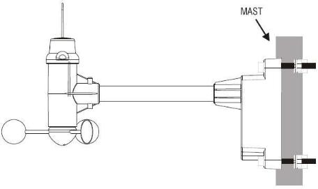
3. Mounting the anemometer
Important: Before mounting, be sure the monitor & anemometer are within the effective transmission
range.
Note: To mount the anemometer, you need a mast (not supplied) about 1 – 1.25 inches (2.54 – 3.1 cm) in diameter, and the hardware necessary to fasten it to the mounting location. If you previously installed such a mast (for mounting antenna, for example), you can mount the anemometer on that mast.
1.If necessary, mount and ground a mast as directed in the instructions provided by the mast.
2.Place the supplied U-shape metal plates around the mast. Insert 4 pieces of the supplied Hex screws through the holes of the U-shape plates and the holes on the anemometer’s mounting bracket.
(The wind vane is above the wind cup and the metal bar of the anemometer is in horizontal level)
3.Tighten the supplied Hex nut onto both ends of each screw
4.Calibrating the anemometer & installing batteries
After mounting the anemometer, follow these steps to calibrate the wind direction so that the anemometer properly measures the wind direction and transmit to the monitor. Be sure battery has been removed from the anemometer before the calibration.
Important: The same calibration (step 1 to 5) is needed for the first set up and every battery
replacement.
1.After mounting the anemometer, loosen the screws on the battery door with a small screwdriver and open the battery door.
2.Use the compass on the anemometer and turn the wind vane so it is pointing due north.

3.Hold the wind vane pointing due north and do not allow it to turn. Insert 2 pieces of AA batteries according to the polarity indicated. The red LED indicator above the battery cover of the anemometer will flash few times right after battery installation. Be sure the vane is pointing due north at the moment when red LED flashes and the calibration is now completed. Replace the battery cover and tighten the screws.
4.If the wind vane is not pointing due north when the red LED first flashes, remove batteries and repeat step 2 & 3.
5.Hold “CHANNEL/SEARCH” buttons on the monitor to search for remote transmitter. Wind direction, wind speed, wind chill & channel-1 temperature/humidity readings will appear if the RF transmission is successful.
5.Selecting a location for the rain gauge
Select a mounting location for the rain gauge that is:
-a flat, level surface
-within 30 meter (100 feet) open area from the monitor. Reduce distance if obstacles is between the rain gauge & the monitor
-in an area not blocked on the top or sides, so rain can freely reach the rain gauge (for example, not under an overhang or too close to a building or fence)
Cautions:
-To prevent false rainfall readings caused by water splashes, do not choose a location that is not level or that is too close to the ground, a swimming pool, lawn sprinklers, or anywhere water might accumulate or run off
-The screen in the cylinder of the rain gauge filters most debris (such as leaves) that might fall into the rain gauge. To avoid frequent build-up of debris in the cylinder, do not mount the rain gauge
too close to the trees or plants
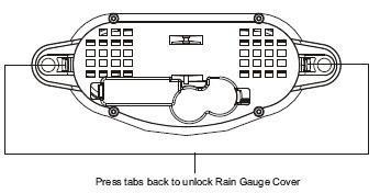
6.Battery Installation for the rain gauge
1. Press the tabs back as indicated below to unlock the rain gauge cover
2.Lift the rain gauge cover off its base. Then carefully remove the packing tape from the bucket assembly
3.Open battery cover and insert 2 pieces of AA batteries according to the polarity indicated. Close the battery cover
4.Replace & lock the rain gauge cover on the base
5.Hold “CHANNEL/SEARCH” button on the monitor for 3 seconds and the total rainfall “- - - -“ will flash. The monitor is now searching for all remote sensors for 2 minutes. Total rainfall reading (in this case “0” mm or inch) will appear within 2 minutes if the RF transmission is successful and the monitor & rain gauge are now within the effective transmission range.
6.If total rainfall “- - - - “ stop flashing and stay on the display after 2 minutes of searching, the RF transmission is failed. Shorten the distance between the monitor & rain gauge. Reset the rain gauge by removing all batteries from the rain gauge and wait for 10 seconds before re-installing the batteries again. Then repeat step 5 (& 6) until the RF communication is completed.
7.Mounting the rain gauge
Before mounting the rain gauge, be sure the rain gauge & monitor are within the transmission effective
range and batteries are installed.
1.Hold the base of the rain gauge flat against the mounting surface then use a level to make sure the rain gauge (as it rest on the mounting surface) is horizontally level.
2.Use a pencil to trace the inside of the mounting holes on the base of the rain gauge to mark the screw locations.
3.Drill a hole in the center of each marked location and insert the supplied plastic screw plugs
4.Hold the rain gauge against the mounting surface so the holes on the base are aligned with the plugs, then thread the supplied washer head screws into each hole and use a screwdriver to tighten them.
 Loading...