

Page 1
REMOTE SENSOR
with OVERRIDE BUTTON
MODEL
ACC-TSENWB
IMPORTANT: READ ALL OF THESE INSTRUCTIONS BEFORE INSTALLING THE SENSOR.
SAFETY CONSIDERATIONS
Read and follow the manufacturer instructions carefully. All wiring must conform to local and national
electrical codes. Improper wiring or installation may damage the sensor.
Recognize safety information. This is the safety alert symbol . When the safety alert symbol is present on
equipment or in the instruction manual, be alert to the potential for personal injury.
Understand the signal words DANGER, WARNING, and CAUTION. These words are used with the safety alert
symbol. DANGER identifies the most serious hazards which will result in severe personal injury or death.
WARNING signifies a hazard which could result in personal injury or death. CAUTION is used to identify
unsafe practices which may result in minor personal injury or property damage.
GENERAL
The Remote Sensor measures indoor air temperature and will send this information to the thermostat. The
sensor measures temperature with a range of -20° to 120° F. The sensor also has an OVERRIDE button which
will place the thermostat into the override mode for two hours. For information on override operation please
consult the Owner’s Manual of your thermostat.
Sensor Location
CORRECT LOCATIONS The Remote Sensor should be mounted approximately five feet from the floor, close to or in a
frequently used room, preferably on an inside partitioning wall or on a section of wall without pipes or ductwork. Mount
the sensor where temperature operating limits are within -20 to 120 F and the humidity operating range is within 0 to 95%
relative humidity, non-condensing.
INCORRECT LOCATIONS The Remote Sensor should NOT be mounted close to a window, on an outside wall, or next to
a door leading to the outside. Do not mount the sensor in a location where it would be exposed to direct light and heat
from a lamp, the sun, a fireplace, or any other temperature-radiating object which may cause a false reading. Finally, do
not mount the sensor close to or in direct airflow from supply registers or return air grilles and in areas with poor air
circulation (such as behind a door or in an alcove).
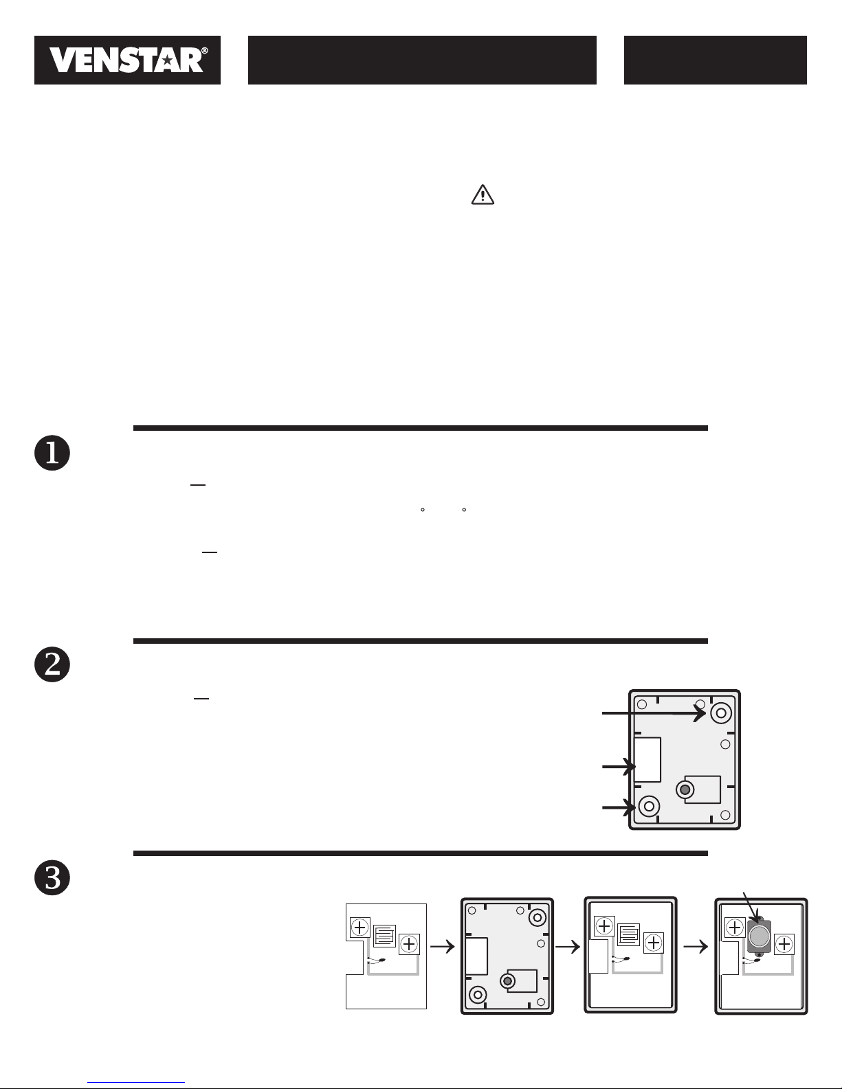
Sensor Installation
INDOOR INSTALLATION Perform the following procedures to install
the sensor:
1. Place the Remote Sensor wall plate on the wall. Mark the
mounting screw holes on the wall through the holes in the
wall plate.
2. Drill two 3/16-in. mounting holes in the wall at the location
marked in Step 1.
3. Mount the Remote Sensor wall plate to the wall with the
screws provided.
Screw hole
Through hole
for wires
Screw hole
Remote Sensor
Wall Plate
Sensor Assembly
Align and press the Remote Sensor circuit
board onto the wall plate as shown. Install the
button onto the circuit board.
Note: The OVERRIDE button can be disabled
by putting non-conductive tape over the
switch pad before installing the OVERRIDE
button onto the circuit board.
©Venstar Inc. 8/11
White
Black
White
OVERRIDE
button
White
Black
P/N 88-941 Rev. 1
Black
Page 2
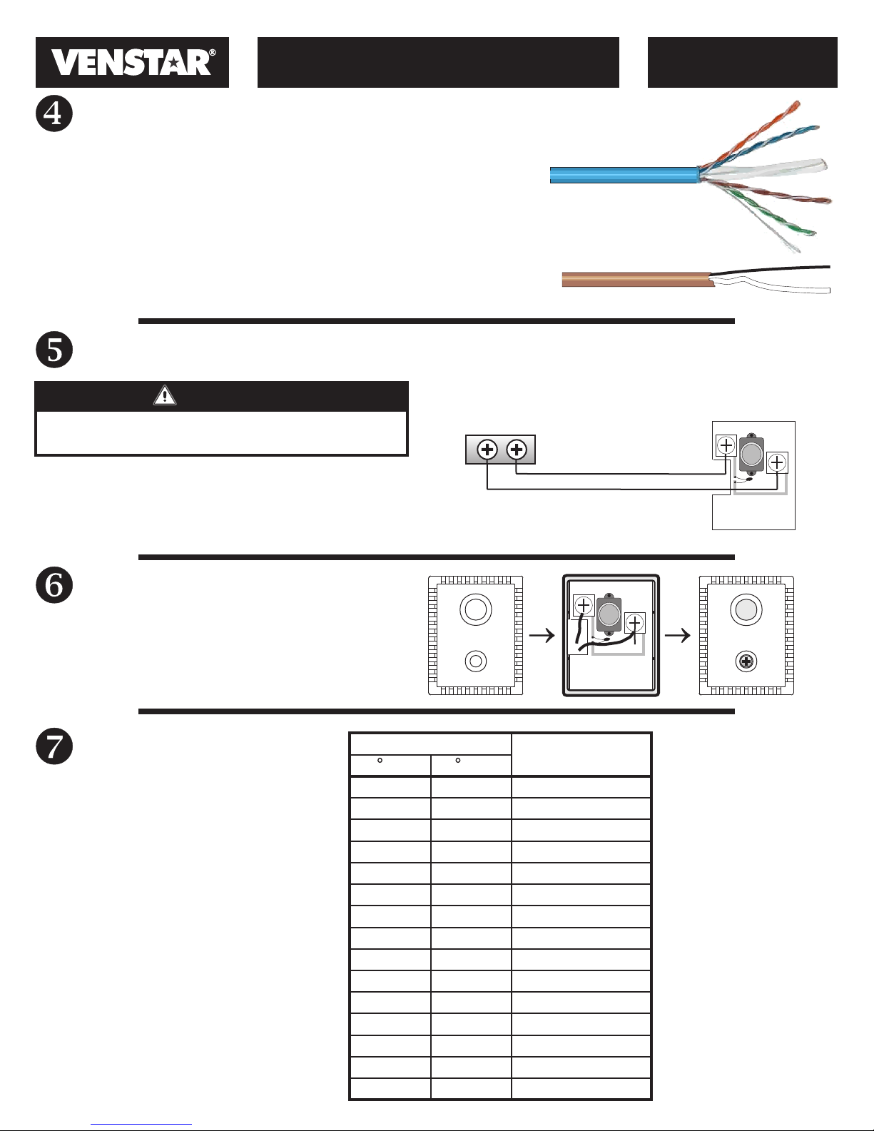
Wiring Requirements
REMOTE SENSOR
with OVERRIDE BUTTON
MODEL
ACC-TSENWB
The Remote Sensor should be connected to the thermostat using
two conductor thermostat cable (18-24 gauge) or solid conductor
CAT 5, CAT 5e, or CAT 6 type network communication cable. This is
an unshielded cable with four twisted pairs of 24 gauge solid wire.
The cable length should not exceed 250 feet.
IMPORTANT: Do not run sensor wiring in the same conduit as the
24VAC thermostat wiring. Electrical interference may cause the
sensor to give incorrect temperature readings.
Sensor Wiring
Thermostat
WARNING
Turn off power to the thermostat before wiring. Death
or injury from electric shock could result.
The connection between the Remote Sensor and the
thermostat must be wired per the connection diagram.
Only two conductors are used, therefore the extra
conductors should be cut from each end of the cable to
prevent shorting. Follow the color coding as shown.
REMOTE/
OUTDOOR
CAT 5 Cable
Thermostat Cable
White +
Remote Sensor
Remote Sensor
Circuit Board
Circuit Board
Black -
Sensor Assembly
Secure the Remote Sensor top cover to the wall plate
using the supplied standard or tamper proof screws.
Air Temperature vs.
Temperature Resistance
NOTE: All sensor wiring
must be in compliance
with all applicable local
and national codes.
©Venstar Inc. 8/11
Air Temperature
F
-20
-10
0
10
20
30
40
50
60
70
80
90
100
110
120
RS-GND
OVERRIDE
Resistance in
C
Ohms
-28.9 106926
-23.3 80485
-17.8 61246
-12.2 47092
-6.7 36519
-1.1 28558
4.4 22537
10 17926
15.6
21.1
26.7
32.2
37.8
43.3
48.9
14356
11578
9398
7672
6301
5203
4317
RS
OVERRIDE
RS+5
P/N 88-941 Rev. 1
 Loading...