

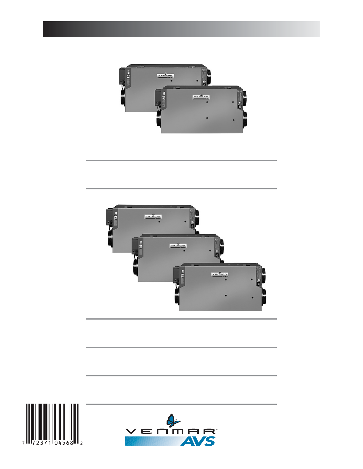
Venmar Solo 1.5, Solo 2.0, Duo 1.9, Duo 1.4, Duo 1.2 Installer Manual
03309 rev. C
Installer Manual
Ventilation systems for residential use only
Duo 1.2 (part no. 43710)
Duo 1.4 (part no. 43700)
Duo 1.9 (part no. 45700)
Solo 1.5 (part nos 43720 and 43725)
Solo 2.0 (part nos 45720 and 45725)
VB0092
VB0093

2
Table of Contents
1. SERVICE ..............................................................................................................4
1.1 3-D Drawing ..................................................................................................4
1.2 Parts Ordering Chart ....................................................................................5
1.3 Technical Support..........................................................................................5
2. SIZING ..................................................................................................................6
3. UNIT TYPE & DEFROST SETTING VS GEOGRAPHICAL LOCATION ....................7
4. TECHNICAL DATA ................................................................................................8
4.1 Air Distribution (Normal Operation) ..............................................................8
4.2 Air Distribution (Defrost and/or Filtration Mode)............................................8
4.3 Defrost Cycles Tables ....................................................................................8
4.4 Dimensions....................................................................................................9
4.5 Controls and Link Options ............................................................................9
4.6 Specifications ................................................................................................9
5. TYPICAL INSTALLATIONS ....................................................................................10
5.1 Fully Ducted System ..................................................................................10
5.2 Exhaust Ducted System
(Source Point Ventilation)
....................................10
5.3 Simplified
(Volume Ventilation)
....................................................................10
6. INSTALLATION ................................................................................................11-16
6.1 Locating and Mounting the Unit ..................................................................11
6.2 Planning of the Ductwork ............................................................................11
6.3 Calculating the Duct Size ............................................................................12
6.3.1 Example Calculation..........................................................................12
6.3.2 Example of a Design for a Fully Ducted System ..............................12
6.4 Installing the Ductwork and Registers....................................................13-14
6.4.1 Fully Ducted System ........................................................................13
6.4.2 Exhaust Ducted System
(Source Point Ventilation)
..........................13
6.4.3 Simplified Installation
(Volume Ventilation)
........................................14
6.5 Connecting the Duct to the Unit ..................................................................15
6.6 Installing the Exterior Hoods ......................................................................16
6.7 Connecting the Drain (Solo only) ................................................................16
7. CONTROL DEVICES ......................................................................................17-18
7.1 Main Controls ..............................................................................................17
7.2 Optional Controls ........................................................................................17
7.3 Other Features ............................................................................................18
3
Table of Contents (cont’d)
About this Manual
8. INSTALLATION OF THE CONTROLS ..............................................................18-22
8.1 Dimensions and Specifications ................................................................18
8.2 Installation of the Main Control............................................................19-21
8.2.1 Altitude Main Control Installation ........................................................19
8.2.2 Venta Main Control Installation............................................................20
8.2.3 Main Control Electrical Connection......................................................21
8.3 Optional Controls Electrical Connection ..................................................21
8.4 Electrical Connection to the Furnace........................................................22
8.5 Furnace Interlock Types............................................................................22
9. WIRING DIAGRAMS ......................................................................................23-24
10. AIR FLOW BALANCING......................................................................................25
11. OVERALL VERIFICATION ....................................................................................26
11.1 Main Controls............................................................................................26
11.2 Optional Controls ......................................................................................26
12. MAINTENANCE / INSTRUCTIONS FOR USER ....................................................27
13. TROUBLESHOOTING......................................................................................27-28
14. REFERENCES ....................................................................................................28
This manual uses the following symbols to emphasize particular information:
NOTE: Indicates supplementary information needed to fully complete an instruction.
WARNING
Identifies an instruction which, if not followed, might cause serious personal injuries including
possibility of death.
!
CAUTION
Denotes an instruction which, if not followed, may severely damage the unit and/or its components.
4
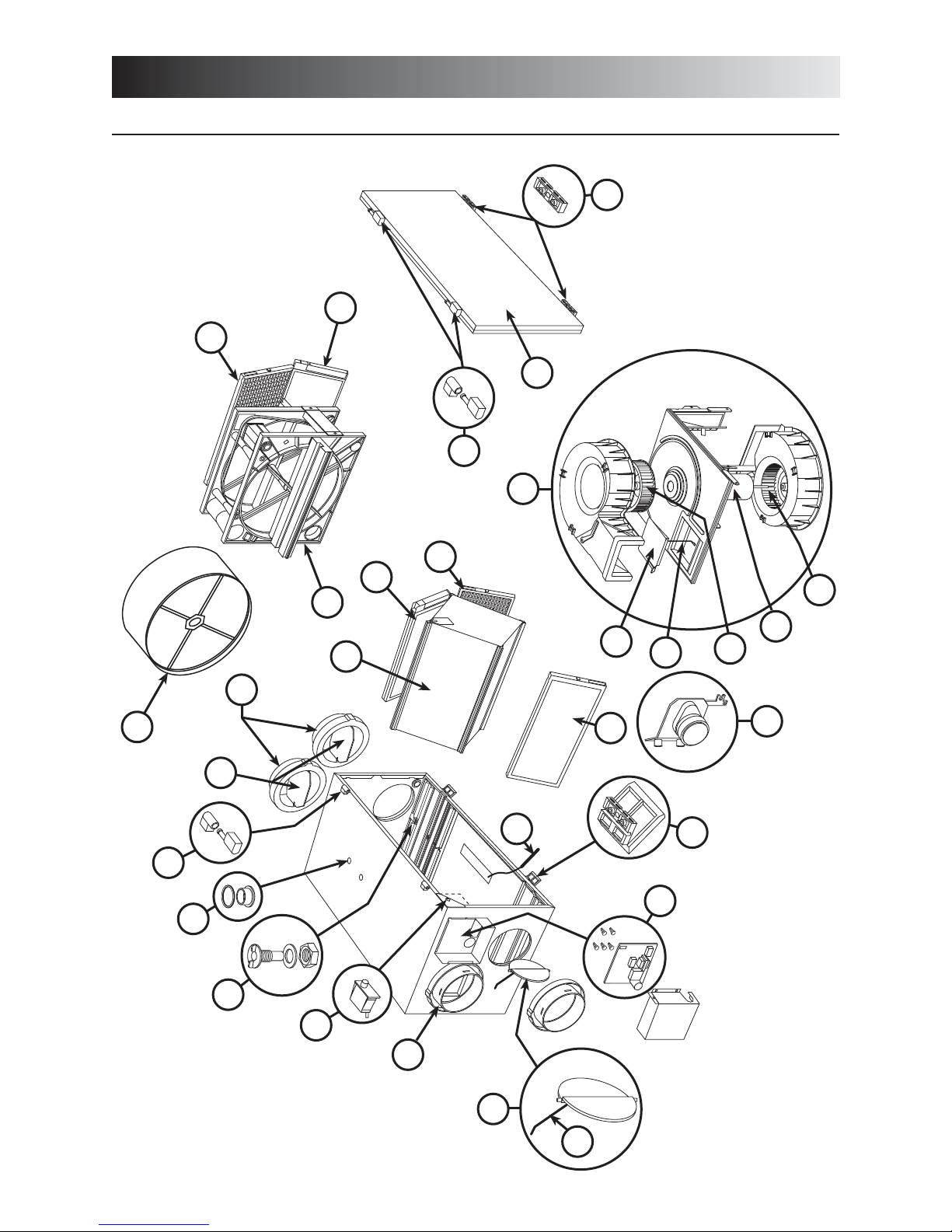
1.1 3-D DRAWING
1. Service
Unit shown in normal position.
8
15
17
14
16
9
25
16
22
21
23
20
8
17
13
18
12
19
10
8
5
3
11
7
6
4
24
1
2
3
VL0023

5
1.2 PARTS ORDERING CHART
1. Service (cont’d)
TO ORDER PARTS: Contact your local distributor.
No Description SOLO 1.5 SOLO 2.0 DUO 1.2 DUO 1.4 DUO 1.9
(A) 43720 (A) 45720 43710 43700 45700
(B) 43725 (B) 45725
1 Double Collar Port no. 2 02257 02257 02257 02257 02257
2 Damper no. 1 (kit) 12454 12454 12454 12454 12454
3 Damper Rod (kit) 13037 13037 13037 13037 13037
4 Electronic Board & spacers (kit) 13038 13038 13039 13039 13039
5 Thermistor (kit) 12895 12895 12895 12895 12895
6 Door Latches & screws
00886 (2) 00886 (2) 00886 (2) 00886 (2) 00886 (2)
00601 (4) 00601 (4) 00601 (4) 00601 (4) 00601 (4)
7 Damper Actuator Assembly 13734 13734 13734 13734 13734
8 Basic Filter 03308 03308 03308 03308 03308
9 Blower Assembly 12908 12912 12909 12909 12911
10 Square Damper (kit) 13033 13033 13033 13033 13033
11 Top Wheel 02238 02238 02238 02239 02239
12 Motor 12109 12157 12109 12109 12157
13 Bottom Wheel 02240 02240 02239 02239 02240
14 Door Ass’y (including 15 & 16) 13346 13346 13346 13346 13346
15 Door Latches (keeper) 00887 (2) 00887 (2) 00887 (2) 00887 (2) 00887 (2)
& Screws 00601 (4) 00601 (4) 00601 (4) 00601 (4) 00601 (4)
16 Hinge Ass’y (kit) 13036 13036 13036 13036 13036
Pleated Optional Filter 03316 03316 03316 03316 03316
17 Charcoal Optional Filter 03315 03315 03315 03315 03315
Electronic Optional Filter 03314 03314 03314 03314 03314
18
12’’ Cassette (incl. motor) N/A N/A - 15184 14’’ Cassette (incl. motor) N/A N/A 15185 - 15185
19 Recovery Core
(A) 03322 (A) 03322
N/A N/A N/A
(B) 03311 (B) 03311
20 Balancing Double Collar Port 02256 02256 02256 02256 02256
21 Balancing Damper 02253 02253 02253 02253 02253
22 Snap Bushing DP-750 03324 (2) 03324 (2) 03324 (2) 03324 (2) 03324 (2)
& O-Ring 03310 (4) 03310 (4) 03310 (4) 03310 (4) 03310 (4)
23 Drain Connector (kit) 03203 03203 N/A N/A N/A
24 Door Switch (SPST), E69 10A 01825 01825 01825 01825 01825
25
Media (14’’ Wheel) N/A N/A 15186 - 15186
Media (12’’ Wheel) N/A N/A - 15187 -
Please take note that parts not listed are not available; those parts require assembly knowledge that only manufacturer can
guarantee.
For assistance, call on weekdays, 8:30 AM to 5:00 PM (Eastern Standard Time).
NOTE: Do not call this number for ordering parts.
Canada & U.S.A.: 1-800-649-0372 (toll free)
1.3 TECHNICAL SUPPORT (FOR ASSISTANCE)
6
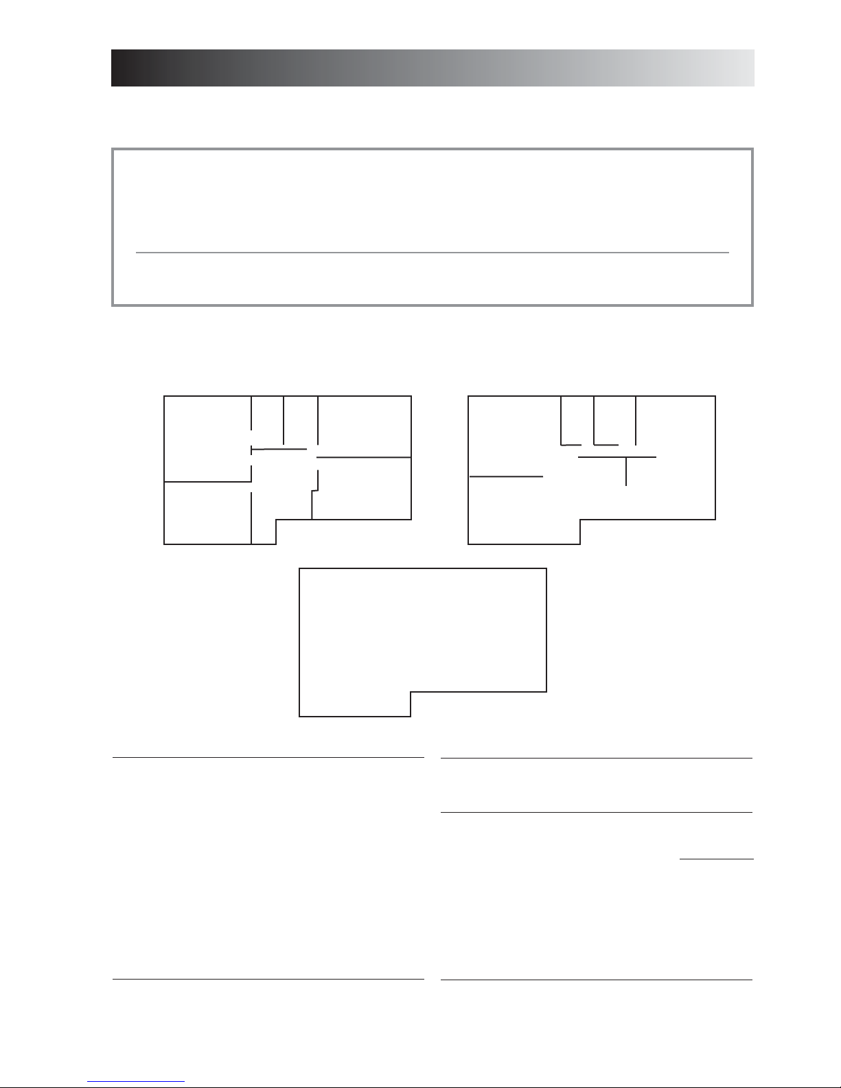
These are the two most common methods used to evaluate the ventilation needs of a house:
CSA F326 and Canadian Building Code:
• High speed: 10 cfm per room
20 cfm for the master bedroom and the basement
• Low speed: 40-60% of high speed
ASHRAE Standard 62-2001:
• 0.35 air change per hour
Refer to ventilation code of your area to determine which method to use.
Example:
2.
Sizing
1320 ft²
1320 ft²
CSA F326
Kitchen (10 cfm)
Dining room (10
cfm)
Living room (10
cfm)
Family room (10
cfm)
Master bedroom (20
cfm)
Bedroom no. 1 (10
cfm)
Bedroom no. 2 (10
cfm)
Bedroom no. 3 (10
cfm)
Bathroom no. 1 (10
cfm)
Bathroom no. 2 (10
cfm)
Bathroom no. 3 (10
cfm)
Laundry room (10
cfm)
Basement (20 cfm)
Total 150
cfm
ASHRAE Standard 62-1989
Volume of basement 10560 ft³
Volume of main floor 10560 ft³
Volume of second floor 10560 ft³
Total volume 31680 ft³
x 0.35/h
11090 ft³/h
÷ 60 (min/h)
Total 185 cfm
1320 ft²
Second floor
Main floor
Basement
Master
bedroom
Bedroom no.1
no. 1
Bathroom
no. 2
Bathroom
Bedroom
no. 2
Bedroom
no. 3
Basement
VH0021A
Laundry
room
no. 3
Living room
Family room
Bathroom
Kitchen
Dining room
7
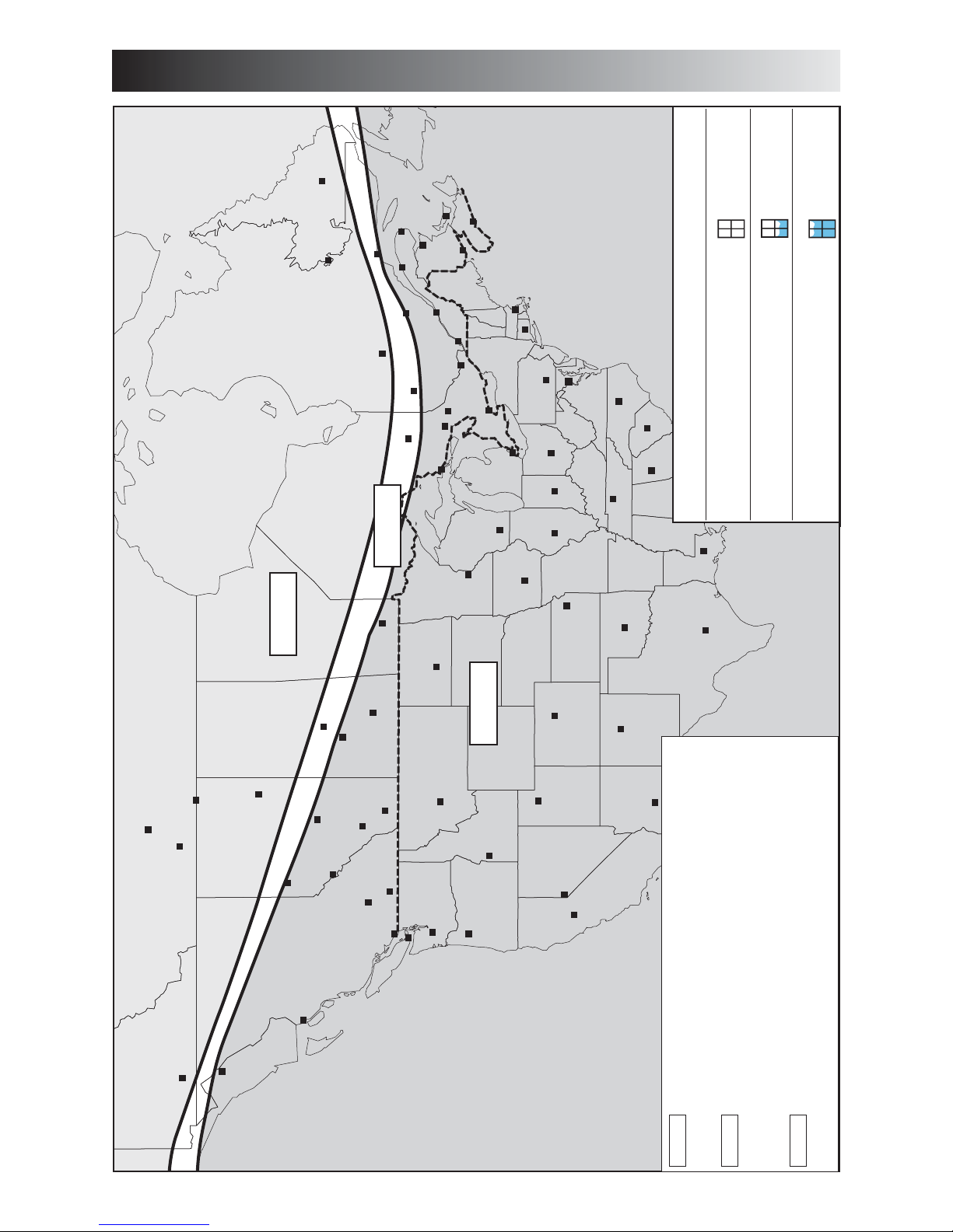
3. Unit Type & Defrost Setting vs Geographical Location
WHITEHORSE
JUNEAU
HAY RIVER
YELLOWKNIFE
PRINCE RUPERT
GRANDE PRAIRIE
FORT MCMURRAY
ZONE A
FORT SMITH
EDMONTON
PRINCE ALBERT
SASKATOON
JASPER
KAMLOOPS
CALGARY
PENTICTON
REGINA
LETHBRIDGE
HELENA
VICTORIA
OLYMPIA
WINNIPEG
SALEM
BOISE
BISMARCK
SALT LAKE CITY
SAULT STE MARIE
ST. PAU L
DES MOINES
MADISON
TIMMINS
HARRISBURG
SACRAMENTO
DENVER
TOPEKA
SUDBURY
TORONTO
DETROIT
INDIANAPOLIS
SANTA FE
SPRINGFIELD
OKLAHOMA CITY
PHOENIX
COLUMBUS
NASHVILLE
ATLANTA
BÂTON ROUGE
AUSTIN
COLUMBIA
RALEIGH
WASHINGTON
OTTAWA
NORTH BAY
VAL -DO R
CHICOUTIMI
HARTFORD
CHIBOUGAMAU
MONTRÉAL
QUÉBEC
BOSTON
GOOSE BAY
LABRADOR CITY
SEPT-ILES
MATANE
GASPÉ
BATHURST
ST-JOHN
HALIFAX
CHARLOTTETOWN
ST JO
ZONE C
ZONE B
RENO
VN0001
ZONE A Solo is recommended.
Set :”extended defrost”
according to Section 9.
ZONE B Solo is recommended but if a Duo unit is used, it has to
be oversized (because of its high humidity transfer efficiency).
Set “
extended defrost” according to Section 9.
ZONE C Solo or Duo (any models). “Extended defrost” not required
(factory defrost strategy pre-set).
SYMPTOM SOLUTION
(condensation)
Indoor air quality problem
DUO
and / or
Excess moisture problem
DUO
and/or
Important excess moisture problem
SOLO
ZONE B & C SELECTION CHART
NORTH AMERICA
VQ0013
8
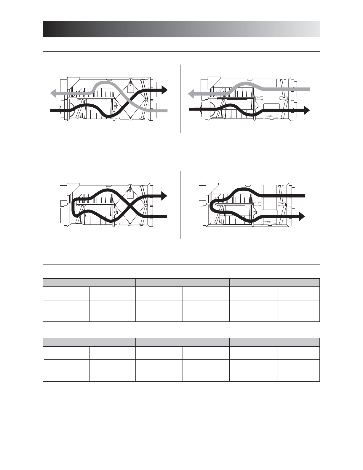
4.1 AIR DISTRIBUTION (NORMAL OPERATION)
4.2 AIR DISTRIBUTION (DEFROST AND/OR FILTRATION MODE)
4. Technical Data
SOLO DUO
STALE AIR
FROM BUILDING
SOLO
FILTERED AIR
TO BUILDING
DUO
FRESH AIR
FROM OUTSIDE
STALE AIR
FROM BUILDING
FRESH AIR
FROM OUTSIDE
FRESH AIR
TO BUILDING
STALE AIR
TO OUTSIDE
FRESH AIR
TO BUILDING
STALE AIR
TO OUTSIDE
STALE AIR
FROM BUILDING
FILTERED AIR
TO BUILDING
STALE AIR
FROM BUILDING
SOLO units
DUO units
Celcius (°C)
-5
-15
-27
Fahrenheit (°F)
23
5
-17
Defrosting (min.)
6
6
6
Operation time
(min.)
between each defrost cycle
60
32
20
Defrosting (min.)
10
10
10
Operation time
(min.)
between each defrost cycle
30
20
15
Outside Temperature Defrost Cycles Extended Defrost Cycles
Celcius (°C)
-5
-15
-27
Fahrenheit (°F)
23
5
-17
Defrosting (min.)
9
9
9
Operation time
(min.)
between each defrost cycle
60
32
20
Defrosting (min.)
10
10
10
Operation time
(min.)
between each defrost cycle
30
20
15
Outside Temperature Defrost Cycles Extended Defrost Cycles
NOTE: THE SOLO AND DUO PERFORMANCE CHARTS ARE LISTED ON THE SPECIFICATION SHEETS OF THESE UNITS.
V
ISIT OUR WEBSITE AT WWW.VENMAR.CA TO ACCESS THOSE DOCUMENTS.
4.3 DEFROST CYCLES TABLES
VF0016
VF0018
VF0019
9
4. Technical Data (cont’d)
Main controls:
• Altitude
• Venta
Optional controls:
• 20/40/60-minute push-button timer
• 60-minute crank timer
• Dehumidistat
Link option:
• Furnace interlock
(used with forced air systems)
4.5 CONTROLS AND LINK OPTIONS
4.6 SPECIFICATIONS
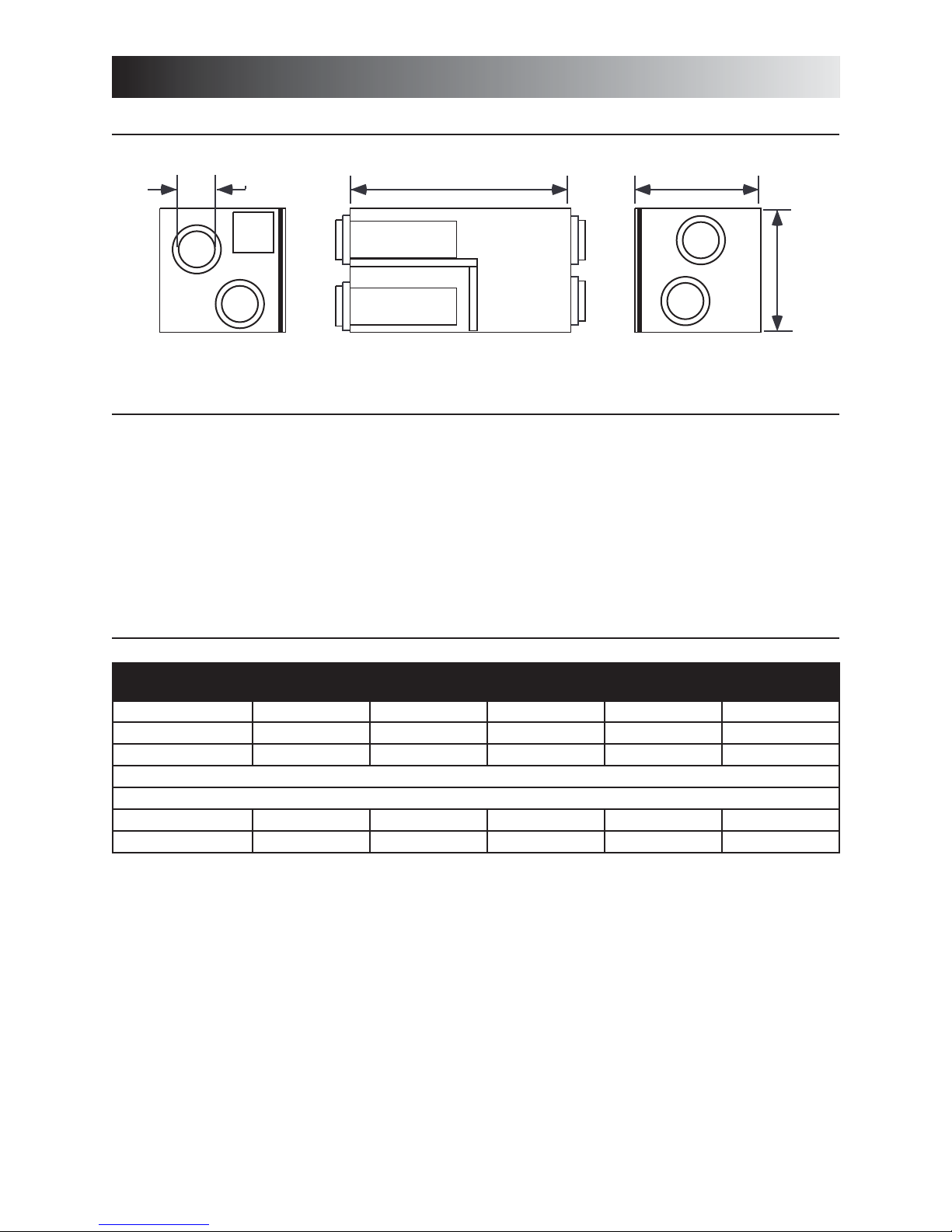
4.4 DIMENSIONS
Model Solo 1.5 Solo 2.0 Duo 1.2 Duo 1.4 Duo 1.9
Weight 65 lb (29.5 kg) 67 lb (30.4 kg) 71 lb (32.2 kg) 71 lb (32.2 kg) 73 lb (33.1 kg)
Port Diameter 6” (152 mm) 6” (152 mm) 6” (152 mm) 6” (152 mm) 6” (152 mm)
Drain Diameter 1/2” (12 mm) 1/2” (12 mm) N/A N/A N/A
Installation Chains and springs (provided with the unit).
Motor Speed High and low speed factory set (optional increased or decreased low speed)
Electrical supply 120 V, 60 Hz 120 V, 60 Hz 120 V, 60 Hz 120 V, 60 Hz 120 V, 60 Hz
Power Consumption 150 watts 240 watts 160 watts 160 watts 250 watts
6” (152 mm)
VK0029A
30¼” (768 mm)
1
17 /8” (435 mm)
16½”
(419 mm)
 Loading...